

Page 1
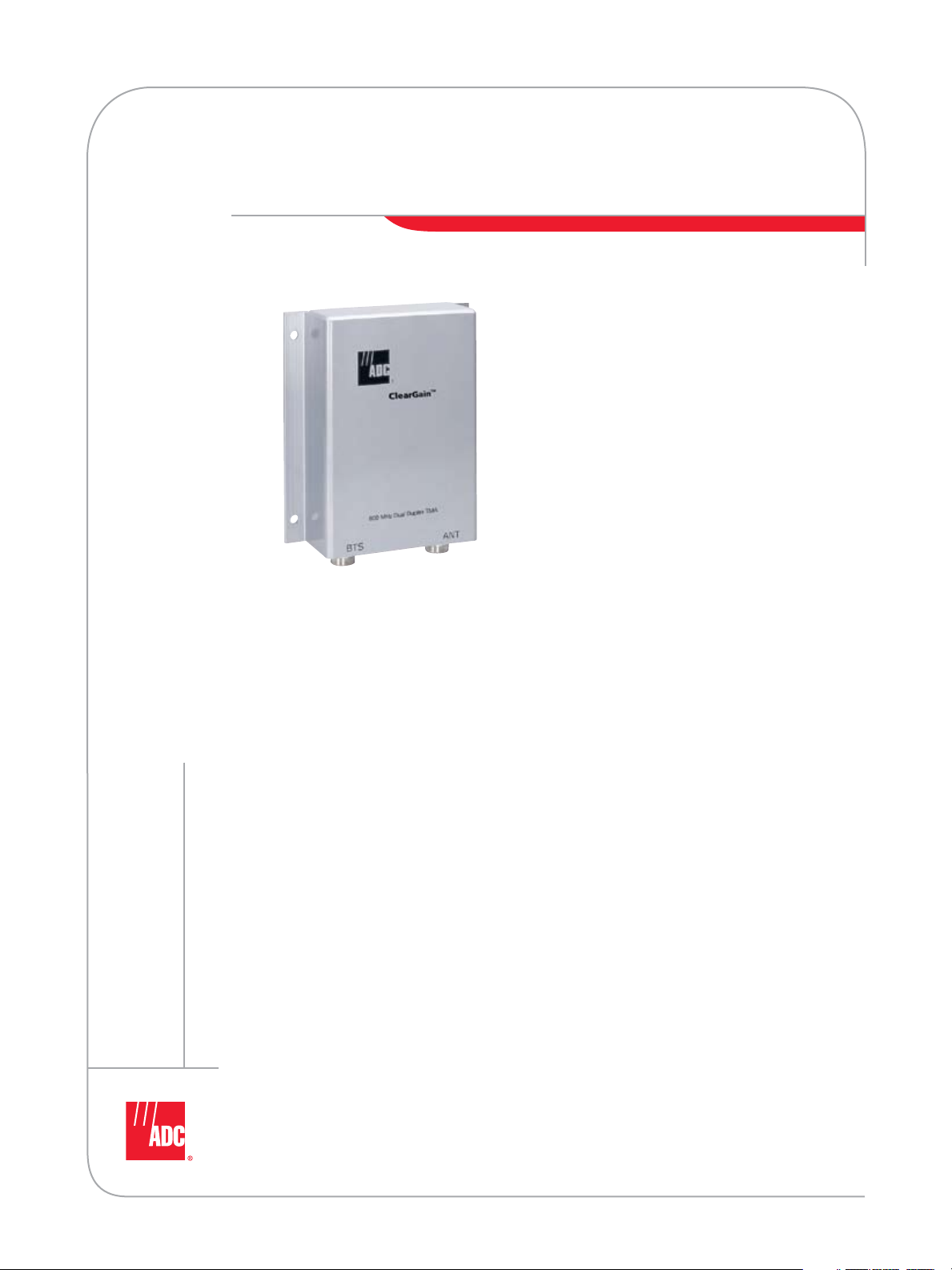
ClearGain® Tower-Mounted Amplifiers
Americas
SPEC SHEET
As mobile usage continues to increase, service providers are faced with the challenge of optimizing
and expanding their wireless networks to provide new and existing services. ADC’s ClearGain®
Tower-Mounted Amplifiers (TMAs) minimize the cost of network expansion and improve quality of
service, allowing service providers to increase profitability from new and existing services.
The ClearGain TMAs improve signal quality by boosting the uplink signal of a mobile system to
increase receiver performance and improve overall coverage.
Features:
Provides amplification of the Band
•
Highly advanced LNA amplifies RX signal for improved receiver performance
•
and increase in coverage
Dual duplex feature reduces the number of feeder cable runs by providing simultaneous
•
operation of TX and RX with low TX loss
Full Band feature provides amplification of the entire band
•
Advanced filtering maintains the lowest possible noise figure for improved quality of service
•
Slim, stackable design conserves tower space and reduces tower-related costs
•
Seamless aluminum sleeve construction protects components from the elements
•
Modular system is fully compatible with all base stations
•
Power and alarming for up to six masthead units is provided from a single unit at the base station
•
w w w . a d c . c o m • + 1 - 9 5 2 - 9 3 8 - 8 0 8 0 • 1 - 8 0 0 - 3 6 6 - 3 8 9 1
Page 2
ClearGain® Tower-Mounted Amplifiers
+ INPUT
NO COM NC
ALARM
MHU
DISCONNECT
Power Distribution Unit
MHU1 MHU2 MHU3 MHU4 MHU5 MHU6
Base
Station
ClearGain™
TMA
ANT
BTS
Bias-T
BTS
Antenna
BTS
Americas
®
Tower-Mounted Amplifiers
ClearGain
Introduction
Unacceptable network quality is one of the main
reasons for mobile subscriber churn. With industry
churn at their current rates, a service provider’s
entire customer base could be lost in as few as
three years. The cost of acquiring new subscribers
to replace the existing customer base can be
enormous. Improvements in quality of service can
directly impact a service provider’s profitability
through the cost savings associated with
increased subscriber retention and the additional
revenue gained from increased billable minutes
of use resulting from improved signal quality.
While subscribers are willing to pay a premium
for data services, improved quality of service is
necessary to provide new data services. Due to
the tradeoff between bit rate and bandwidth
inherent to data services, improved signal
quality is required to achieve the same level of
performance at even higher data rates. ADC’s
ClearGain Tower-Mounted Amplifiers help provide
this improvement in signal quality.
TMAs improve signal quality by boosting the
uplink (RX) signal of a mobile system immediately
after the antenna. This compensates for the loss
in signal strength that occurs when the signal
is passed through the coaxial feeder cable to
the base transceiver station (BTS) at the base
of the tower. ClearGain TMAs perform this
amplification with the lowest possible noise
contribution, resulting in a substantial increase
in receiver performance and an improvement in
overall coverage. These improvements in quality
of service allow mobile
subscribers to place more
calls, make longer calls,
and successfully complete
calls in an expanded
geographic area, resulting
in increased revenue.
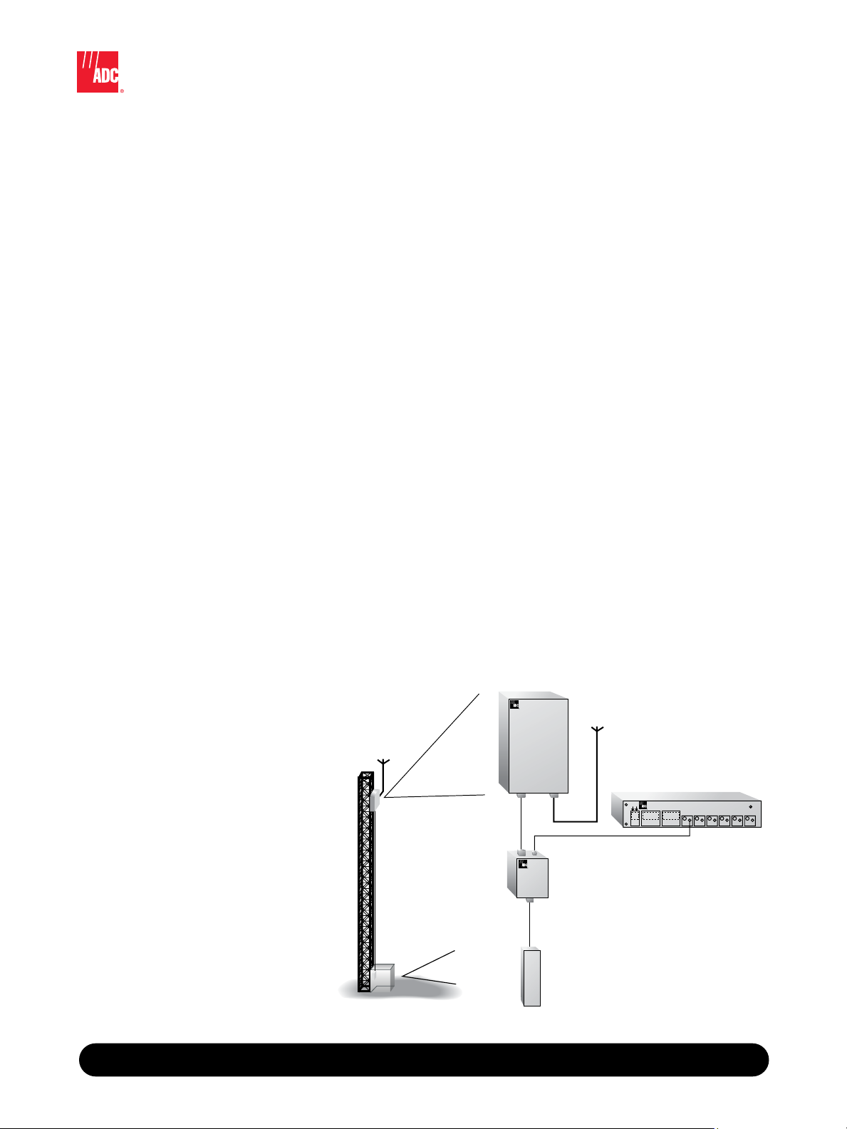
System Overview
The ClearGain TMA system is modular, consisting
of a Masthead Unit (MHU), a Power Distribution
Unit (PDU) and a Bias-T Unit. This system provides
full compatibility with all base stations. The
ClearGain MHU offers dual duplex operation and
incorporates a highly advanced fixed-gain, lownoise amplifier (LNA) and high-performance filters
for added reliability. The MHU amplifies each band
to maximize signal quality and optimize coverage.
The ClearGain MHU features a slim, lightweight
design. This allows two ClearGain TMAs to
be mounted with one set of brackets thereby,
conserving valuable and costly tower space
and reducing clutter on the tower. The TMA
is protected with a strong, aluminum sleeve
construction designed to ensure superior weather
protection and resistance to corrosion, resulting in
increased reliability.
In the ClearGain TMA system, DC power is
supplied to the MHU from a ClearGain PDU. The
PDU also provides alarming and monitoring of the
feeder cable and up to six MHUs from a single
unit. The flexible design of the ClearGain PDU
allows it to be rack- or wall-mounted on the side
of a BTS cabinet.
An external Bias-T Unit is used in conjunction
with the ClearGain PDU. The Bias-T inserts DC
power onto the coaxial cable and extracts alarm
and monitoring signals from the coaxial cable.
8 / 0 7 • 1 0 5 1 8 7 A E
w w w . a d c . c o m • + 1 - 9 5 2 - 9 3 8 - 8 0 8 0 • 1 - 8 0 0 - 3 6 6 - 3 8 9 1
2
Page 3

ClearGain® Tower-Mounted Amplifiers
Americas
DD800 Full Band Typical Specifications
ELECTRICAL
Nominal Impedance of RF Inputs and Outputs:
Frequency Range:
TX: 869-894 MHz
RX: 824-849 MHz
Passband (RX)
Gain: 12 dB
Noise Figure: 1.5 dB
Dynamic Range
Input at 1 dB Gain Compression: 0 dBm
IIP3: +13 dBm
Max Input Power: +10 dBm
851 MHz Rejection: <30 dB
Bypass Insertion Loss: 2.0 dB
Isolation in Tx Path: 80 dB
Rejection 1850-1998 MHz: 80 dB
Insertion Loss of TX Path (TX to Antenna):
Passband Return Loss
TX Band: >18 dB
RX Band: >18 dB
Intermodulation:
Maximum Input Power (RMS Power):
Tx Rejection in Rx Band:
-120 dBm
500 W
40 dB
50 Ohm
0.4 dB
®
Tower-Mounted Amplifiers
ClearGain
POWER
Operational Voltage:
Operational Current:
PHYSICAL
Dimensions (HxWxD):
Weight:
Color:
Housing:
CONNECTORS
Antenna Connector:
BTS Connector:
ENVIRONMENTAL
Operating Temperature:
Lightning Protection:
Vibration
Storage: ETS3019-1-1
Transport: ETS3019-1-2
Operation: ETS3019-1-3
REGULATORY
EMC:
APPROVALS
FCC:
UL:
6.3 kg (13.9 lbs.)
Silver
ETS300 342-2
Part 15, Class A
1950
7 to 15 Vdc
140 ±10 mA
332 mm x 250 mm x 84 mm
Aluminum
7/16 DIN female
7/16 DIN female
-40°C to +60°C
IEC 61000-4-5
QUALITY
8 / 0 7 • 1 0 5 1 8 7 A E
w w w . a d c . c o m • + 1 - 9 5 2 - 9 3 8 - 8 0 8 0 • 1 - 8 0 0 - 3 6 6 - 3 8 9 1
MTBF:
900,000 hours
3
Page 4

ClearGain® Tower-Mounted Amplifiers
Americas
DD800 B-Band Typical Specifications
ELECTRICAL
Nominal Impedance of RF Inputs and Outputs:
Frequency Range:
TX: 880-894 MHz
RX: 835-849 MHz
Passband (RX)
Gain: 12 dB
Noise Figure: 1.7 dB
Dynamic Range
Input at 1 dB Gain Compression: 0 dBm
IIP3: +13 dBm
Max Input Power: +10 dBm
Antenna Isolation 851-869 MHz: >35 dB
Bypass Insertion Loss: 2.0 dB
Isolation in Tx Path: 80 dB
Rejection 1850-1998 MHz: 80 dB
Insertion Loss of TX Path (TX to Antenna):
Passband Return Loss
TX Band: >18 dB
RX Band: >18 dB
Intermodulation:
Maximum Input Power (RMS Power):
Tx Rejection in Rx Band:
-120 dBm
500 W
40 dB
50 Ohm
0.4 dB
®
Tower-Mounted Amplifiers
ClearGain
8 / 0 7 • 1 0 5 1 8 7 A E
POWER
Operational Voltage:
Operational Current:
Alarm Current Level:
PHYSICAL
Dimensions (HxWxD):
(13 in x 9.8 in x 3.3 in)
Weight:
Color:
Housing:
CONNECTORS
Antenna Connector:
BTS Connector:
ENVIRONMENTAL
Operating Temperature:
Lightning Protection:
Vibration
Storage:
Transport:
Operation:
REGULATORY
EMC:
APPROVALS
FCC:
UL:
QUALITY
MTBF:
6.3 kg (13.9 lb)
Silver
ETS300 342-2
Part 15, Class A
1950
900,000 hours
7 to 20 Vdc
140 ±10 mA
350 ± 10 mA
332 mm x 250 mm x 84 mm
Aluminum
7/16 DIN female
7/16 DIN female
-40° to +60° C
IEC 61000-4-5
ETS3019-1-1
ETS3019-1-2
ETS3019-1-4
w w w . a d c . c o m • + 1 - 9 5 2 - 9 3 8 - 8 0 8 0 • 1 - 8 0 0 - 3 6 6 - 3 8 9 1
4
Page 5

ClearGain® Tower-Mounted Amplifiers
Americas
DD1900 Full Band Typical Specifications
ELECTRICAL
Nominal Impedance of RF Inputs and Outputs:
Frequency Range
TX: 1930-1990 MHz
RX: 1850-1910 MHz
Passband (RX)
Gain: 12 dB
Noise Figure: 1.6 dB
Dynamic Range
Input at 1 dB Gain Compression: +3 dBm
IIP3: +13 dBm
Max Input Power: +10 dBm
1915 MHz Rejection: <15 dB
1916 MHz Rejection: <30 dB
Bypass Inserion Loss: 2.0 dB
Isolation in Tx Path: 80 dB
Rejection 824-894 MHz: 80 dB
Insertion Loss of TX Path (TX to Antenna):
Passband Return Loss
TX Band: >18 dB
RX Band: >18 dB
Intermodulation:
Maximum Input Power (RMS Power):
Tx Filter Rejection in Rx Band:
-120 dBm
250 W
40 dB
50 Ohm
.4 dB
®
Tower-Mounted Amplifiers
ClearGain
8 / 0 7 • 1 0 5 1 8 7 A E
POWER
Operational Voltage:
Operational Current:
Alarm Current Level:
PHYSICAL
Dimensions (HxWxD):
Weight:
Color:
Housing:
CONNECTORS
Antenna Connector:
BTS Connector:
ENVIRONMENTAL
Operating Temperature:
Lightning Protection:
Vibration
Storage: ETS3019-1-1
Transport: ETS3019-1-2
Operation: ETS3019-1-3
REGULATORY
EMC:
APPROVALS
FCC:
UL:
QUALITY
MTBF:
5.5 kg (12.1 lbs.)
Silver
ETS300 342-2
Part 15, Class A
1950
900,000 hours
7 to 15 Vdc
140 ± 10 mA
350 ± 20 mA
297 mm x 287 mm x 70 mm
Aluminum
7/16 DIN female
7/16 DIN female
-40ºC to +60ºC
IEC61000-4-5
w w w . a d c . c o m • + 1 - 9 5 2 - 9 3 8 - 8 0 8 0 • 1 - 8 0 0 - 3 6 6 - 3 8 9 1
5
Page 6

ClearGain® Tower-Mounted Amplifiers
Americas
DD1900 Full Band with 800 Bypass Typical Specifications
ELECTRICAL
Nominal Impedance of RF Inputs and Outputs:
Frequency Range
TX: 1930-1990 MHz
RX: 1850-1910 MHz
Passband (RX)
Gain: 12 dB
Noise Figure: 1.6 dB
Dynamic Range
Input at 1 dB Gain Compression: +3 dBm
IIP3: +15 dBm
Insertion Loss TX Path (TX to ANT): . 4 dB
1915 MHz Rejection: <15 dB
1916 MHz Rejection: <30 dB
Bypass Insertion Loss: 2.0 dB
Isolation in Tx Path: 80 dB
Rejection 824-894 MHz: 80 dB
Max Input Power:
Passband Return Loss
TX Band: >18 dB
RX Band: >18 dB
Intermodulation:
Maximum Input Power (RMS Power):
Tx Filter Rejection in Rx Band:
+10 dBm
-120 dBm
250 W
40 dB
50 Ohm
®
Tower-Mounted Amplifiers
ClearGain
8 / 0 7 • 1 0 5 1 8 7 A E
POWER
Operational Voltage:
Operational Current:
Alarm Current Level:
PHYSICAL
Dimensions (HxWxD):
Weight:
Color:
Housing:
CONNECTORS
Antenna Connector:
BTS Connector:
ENVIRONMENTAL
Operating Temperature:
Lightning Protection:
Vibration
Storage: ETS3019-1-1
Transport: ETS3019-1-2
Operation: ETS3019-1-3
REGULATORY
EMC:
APPROVALS
FCC:
UL:
QUALITY
MTBF:
5.5 kg (12.1 lbs.)
Silver
ETS300 342-2
Part 15, Class A
1950
900,000 hours
7 to 20 Vdc
140 ± 10 mA
350 ± 20 mA
297 mm x 287 mm x 70 mm
Aluminum
7/16 DIN female
7/16 DIN female
-40°C to +60°C
IEC 61000-4-5
w w w . a d c . c o m • + 1 - 9 5 2 - 9 3 8 - 8 0 8 0 • 1 - 8 0 0 - 3 6 6 - 3 8 9 1
6
Page 7

®
Tower-Mounted Amplifiers
ClearGain
8 / 0 7 • 1 0 5 1 8 7 A E
ClearGain® Tower-Mounted Amplifiers
Americas
Dual Band 800/1900 MHz Full Band Typical Specifications
ELECTRICAL
Nominal Impedance of RF Inputs and Outputs:
Frequency Range
TX: 800: 869-894 MHz
1900: 1930-1990 MHz
RX: 800: 824-849 MHz
1900: 1850-1910 MHz
Filter Bandwidth:
Passband (RX)
Gain: 12 dB
Noise Figure:
800: 1.5 dB
1900: 1.6 dB
Dynamic Range
Input at 1 dB Gain Compression: +0 dBm
IIP3: +13 dBm
Max. Input Power: +10 dBm
851 MHz Rejection: <30 dB
1915 MHz Rejection: <15 dB
1916 MHz Rejection: <30 dB
Bypass Insertion Loss:
Isolation in TX Path:
Insertion Loss of TX Path (TX to Antenna):
Passband Return Loss:
TX Band: >18 dB
RX Band: >18 dB
Intemodulation:
Max. Input Power (RMS Power):
800: 500 W
1900: 250 W
Tx Filter Rejection in RX Path:
POWER
Operational Voltage:
Operational Current:
Alarm Current Level:
PHYSICAL
Dimensions (HxWxD):
Weight:
Color:
Housing:
CONNECTORS
Antenna Connector:
BTS Connector:
ENVIRONMENTAL
Operating Temperature:
Lightning Protection:
Vibration:
Storage: ETS3019-1-1
Transport: ETS3019-1-2
Operation: ETS3019-1-3
REGULATORY
EMC:
APPROVALS
FCC: Part 15, Class A
UL:
QUALITY
MTBF:
10.5 kg (22.5 lbs.)
Silver
ETS300 342-2
1950
900,000 hours
25/60 MHz
2.0 dB
80 dB
-120 dBm
40 dB
7 to 20 Vdc
280 ± 10 mA
350-520 mA
357 mm x 287 mm x 149 mm
Aluminum
7/16 DIN female
7/16 DIN female
-40° to +60 °C
IEC 61000-4-5
50 Ohm
4 dB
w w w . a d c . c o m • + 1 - 9 5 2 - 9 3 8 - 8 0 8 0 • 1 - 8 0 0 - 3 6 6 - 3 8 9 1
7
Page 8

®
Tower-Mounted Amplifiers
ClearGain
ClearGain® Tower-Mounted Amplifiers
Americas
STRB-NF-NM-G-KIT STRB-NM-NF-G-KIT STRB-DM-DF-G-KIT STRB-DF-DM-G-KIT
Bias-T Units
ADC’s newly enhanced Bias-T Units can be used indoors and outdoors in conjunction with the ClearGain
power distribution unit (PDU). These versatile units, also known as a DC current injector, insert DC
power into the coaxial cable and extract alarm and monitoring signals from the coaxial cable. These
units can also be used with a SMART PDU.
Bias-T Unit Typical Specifications
PRODUCT CONFIGURATION
Main path connectors:
DC injection/Sample port connector:
Mounting and grounding:
screw / brk - bracket)
TECHNICAL DATA
Impedance:
Frequency range:
Return loss:
Insertion loss:
RF CW power:
PIM 3rd order:
Surge current handling capability:
Operating temperature:
Waterproof degree:
DC injection / DC bypass current:
DC supply / DC bypass voltage:
MTBF:
Size:
(4.9 in x 4.3 in x 1.8 in)
Weight:
600,000 hours
125 mm x 110 mm x 45 mm
0.8 kg (1.8 lbs.)
Refer to ordering information for configurations
TNC jack (female)
/M8 / brk (MH - bulkhead mounting/ M -
50 ohms
800 to 2200 MHz
> 19 dB
< 0.2 dB
500 W
-108 dBm
3kA single
-40°C to + 65°C
IP 65
< 2 A
< 48 V
8 / 0 7 • 1 0 5 1 8 7 A E
w w w . a d c . c o m • + 1 - 9 5 2 - 9 3 8 - 8 0 8 0 • 1 - 8 0 0 - 3 6 6 - 3 8 9 1
8
Page 9

ClearGain® Tower-Mounted Amplifiers
Americas
Singlemode and Dual Mode 800/1900 MHz Power Distribution Unit
Time and space are important considerations when selecting and installing wireless components at base
transceiver station sites. The simple, compact design of ADC’s ClearGain Power Distribution Unit (PDU) is
intended to help service providers save both. From a compact unit that is easily mounted on a wall or a
rack, ClearGain PDUs provide power and alarming for ADC’s tower-mounted amplifiers.
Features:
Provides power and alarm functions for on-site monitoring of masthead units (MHUs)
•
Monitors condition of feeder cable
•
Wall- or rack-mountable to fit available space
•
LED indicators for alarm functions
•
Simple, compact design allows for easy installation and connections
•
®
Tower-Mounted Amplifiers
ClearGain
8 / 0 7 • 1 0 5 1 8 7 A E
The ClearGain PDU is an integrated unit that provides power and alarm functions for the ClearGain
TMA system. The ClearGain Singlemode PDU provides power for up to six single frequency TMAs. For
dual band systems, the ClearGain Dual Mode PDU provides power for up to six dual band TMAs or
twelve multi-frequency systems that amplify a single frequency.
The PDU monitors the current of the MHU. If an MHU fails, the ClearGain PDU gives an alarm
indication. The ClearGain PDU also monitors the condition of the feeder cable. Alarm indicators identify
failure in the feeder cable or MHUs and in which MHU the failure occurred, providing fast and easy onsite diagnostics. The flexible design of ClearGain PDUs allows them to be rack-mounted or mounted
indoors on the wall or on the side of a BTS cabinet.
An external Bias-T unit is used in conjunction with the PDU and is designed to connect directly into the
BTS coaxial connector. Bias-T units are available with various connector types, with gas tube arrestors for
lightning protection on the ANT and MHU ports. Quarter wave stub lightning protection is integrated on
the BTS port of the Bias-T units.
w w w . a d c . c o m • + 1 - 9 5 2 - 9 3 8 - 8 0 8 0 • 1 - 8 0 0 - 3 6 6 - 3 8 9 1
9
Page 10

®
Tower-Mounted Amplifiers
ClearGain® Tower-Mounted Amplifiers
Americas
Singlemode and Dual Mode 800/1900 MHz PDU Typical Specifications
ELECTRICAL
Input Voltage:
Output Voltage:
Maximum Current Drawn:
PHYSICAL
Dimensions (HxWxD):
Weight:
Color:
CONNECTORS
Output for MHUs:
Power Connector:
General Alarm Connector:
Indicators
Singlemode PDU: Green OK/NOK LEDs
Red General Alarm LED
Dual Mode PDU: Green/Yellow OK/NOK LEDs
Red General Alarm LEDs
Alarm output: Alarm output is isolated 3-pin relay connection
Normally open and normally closed connection
available
ENVIRONMENT
Storage:
Transport:
Operation:
Housing:
Temperature Range (Indoor Use):
Lightning Protection:
APPROVALS
QUALITY
ISO 9001 quality system
ACCESSORIES
Basic Accessories:
grounding cable (2 m) and wall mounting screws
Optional Accessories:
<460 g
Silver
20-56 Vdc positive/negative ground
18 Vdc each
3.8A
43 x 196 x 103 mm (1.69" x 7.72" x 4.06")
SMB, male (qty 6)
4-pin male
3-pin male
ETS3019-1-1
ETS3019-1-2
ETS3019-1-3
IP40
-20ºC to +65ºC (-4ºF to +149ºF)
IEC 1000-4-5 EMC
UL
MTBF 250,000 hours. Manufactured under
Power supply cable (10 m), alarm cable (10 m),
Mounting hardware for 19” rack mount
ClearGain
8 / 0 7 • 1 0 5 1 8 7 A E
w w w . a d c . c o m • + 1 - 9 5 2 - 9 3 8 - 8 0 8 0 • 1 - 8 0 0 - 3 6 6 - 3 8 9 1
10
Page 11

ClearGain® Tower-Mounted Amplifiers
Americas
O r d e r i n g I n f o r m a t i o n
Description Catalog Number
ClearGain Masthead Units
DD800 Full Band CG-800DD-FULL-DIN
DD800 B-Band CG0800DDB14DTTX
DD1900 Full Band CG-1900DD-FULL-DIN
DD1900 Full Band w/800 Bypass CG1900DDBFBDTBP
Full Band 800/1900 MHz CG-1900/800-DB-FB-DIN
Bias-T Kits*
7/16 DIN male to BTS, 7/16 DIN female to ANT STRB-DM-DF-G-KIT
7/16 DIN female to BTS, 7/16 DIN male to ANT STRB-DF-DM-G-KIT
N male to BTS, N female to ANT STRB-NM-NF-G-KIT
N female to BTS, N male to ANT STRB-NF-NM-G-KIT
Power Distribution Units
Single Mode PDU; includes power cable and grounding cable CG-PDU-SMPWR
Dual Mode PDU; includes power cable and grounding cable CG-PDU-DMPWR
®
*Bias-T, DC Cable 4.25 meters (SMB to TNC), Grounding Cable 1.5 meters (one end terminated)
Tower-Mounted Amplifiers
ClearGain
8 / 0 7 • 1 0 5 1 8 7 A E
w w w . a d c . c o m • + 1 - 9 5 2 - 9 3 8 - 8 0 8 0 • 1 - 8 0 0 - 3 6 6 - 3 8 9 1
11
Page 12

ClearGain® Tower-Mounted Amplifiers
Americas
Creating a Bill of Materials
A typical site includes three components in various quantities.
You have six TMA options:
1. CG-800DD-FULL-DIN DD800 Full Band TMA, DIN Connectors
2. CG-800DDB14DT00 DD800 B-Band TMA, DIN Connectors
3. CG-1900DD-FULL-DIN DD1900 Full Band TMA, DIN Connectors
4. CG-1900W800-FULL-DIN DD1900 with 800 Bypass Full Band TMA, DIN Connectors
5. CG1900DDBFBDTBP DD1900 with 800 Bypass Full Band TMA with
DC Block, DIN Connectors
6. CG-1900/800-DB-FB-DIN Dual Band-Full Band TMA, DIN Connectors
SPEC SHEET
The TMAs include: • Mounting hardware
• Grounding cable/strap (length 1.5 meters)
Ordering information: Order two per sector
You have four Bias-T options (based on connector type and orientation):
1. STRB-DF-DM-G-KIT DIN Female to BTS Port, DIN Male to ANT Port
2. STRB-DM-DF-G-KIT DIN Male to BTS Port, DIN Female to ANT Port
3. STRB-NF-NM-G-KIT N Female to BTS Port N Male to ANT Port
4. STRB-NM-NF-G-KIT N Male to BTS Port, N Female to ANT Port
The Bias-Ts include: • Grounding cable/strap (length 1.5 meters)
• Bias-T
Ordering information: Order two per sector
You have two PDU options:
1. CG-PDU-SMPWR Single Power PDU
2. CG-PDU-DMPWR Dual Power PDU*
*Typically used in conjunction with the Dual Power TMA
The PDUs include: • Power cable (length 10 meters)
• Alarm cable (length 10 meters)
• Grounding cable/str
Ordering information: Order one per site
Optional Accessories:
Longer Bias-T Cable CG-PDU-30CABLE (30 foot Bias-T cable)
PDU Rack Mounting Brackets AUX-000076 (19" rack mounting bracket)
AUX-000076 and EB-17P (23" mounting bracket)
AUX-000084 (Siemens cabinet mounting bracket)
cable; go from Bias-T to the PDU (length 14 feet)
ap (length 1.5 meters)
Website: www.adc.com
From North America, Call Toll Free: 1-800-366-3891 • Outside of North America: +1-952-938-8080
Fax: +1-952-917-3237 • For a listing of ADC’s global sales office locations, please refer to our website.
ADC Telecommunications, Inc., P.O. Box 1101, Minneapolis, Minnesota USA 55440-1101
Specifications published here are current as of the date of publication of this document. Because we are continuously
improving our products, ADC reserves the right to change specifications without prior notice. At any time, you may
verify product specifications by contacting our headquarters office in Minneapolis. ADC Telecommunications, Inc.
views its patent portfolio as an important corporate asset and vigorously enforces its patents. Products or features
contained herein may be covered by one or more U.S. or foreign patents. An Equal Opportunity Employer
105187AE 8/07 Original © 2007 ADC Telecommunications, Inc. All Rights Reserved
 Loading...