

Page 1

ADCP-75-214
September 2006
ClearGain® 1800 MHz and 2100 MHz Dual
Inline Tower Mounted Amplifier System
User Manual
Issue 2
1383772 Rev A
Page 2

ADCP-75-214 • Issue 2 • September 2006 • Preface
COPYRIGHT
© 2006, ADC Telecommunications, Inc.
All Rights Reserved
REVISION HISTORY
ISSUE DATE REASON FOR CHANGE
1 06/2006 Original
2 09/2006 Add support for 1800MHz System
TRADEMARK INFORMATION
ADC and ClearGain are registered trademarks of ADC Telecommunications, Inc.
DISCLAIMER OF LIABILITY
Contents herein are current as of the date of publication. ADC reserves the right to change the contents without prior notice. In no
event shall ADC be liable for any damages resulting from loss of data, loss of use, or loss of profits and ADC further
disclaims any and all liability for indirect, incidental, special, consequential or other similar damages. This disclaimer of
liability applies to all products, publications and services during and after the warranty period.
This publication may be verified at any time by contacting ADC Technical Assistance Center at 1-800-366-3891, extension 63475
(in U.S.A. or Canada) or 952-946-3475 (outside U.S.A. and Canada), or by e-mail to bcg_tac@adc.com.
Page ii
ADC Telecommunications, Inc.
P.O. Box 1101, Minneapolis, Minnesota 55440-1101
In U.S.A. and Canada: 1-800-366-3891
Outside U.S.A. and Canada: (952) 938-8080
Fax: (952) 946-3292
Page 3

TABLE OF CONTENTS
Content Page
ABOUT THIS MANUAL . . . . . . . . . . . . . . . . . . . . . . . . . . . . . . . . . . . . . . . . . . . . . . . . . . . . . . . . . . . . . . . . . . . . . . . . . v
ADMONISHMENTS . . . . . . . . . . . . . . . . . . . . . . . . . . . . . . . . . . . . . . . . . . . . . . . . . . . . . . . . . . . . . . . . . . . . . . . . . . . v
Certification . . . . . . . . . . . . . . . . . . . . . . . . . . . . . . . . . . . . . . . . . . . . . . . . . . . . . . . . . . . . . . . . . . . . . . . . . . . . . . . . v
Standards . . . . . . . . . . . . . . . . . . . . . . . . . . . . . . . . . . . . . . . . . . . . . . . . . . . . . . . . . . . . . . . . . . . . . . . . . . . . . . . . . v
LIST OF ACRONYMS . . . . . . . . . . . . . . . . . . . . . . . . . . . . . . . . . . . . . . . . . . . . . . . . . . . . . . . . . . . . . . . . . . . . . . . . . .vi
1 PRODUCT OVERVIEW . . . . . . . . . . . . . . . . . . . . . . . . . . . . . . . . . . . . . . . . . . . . . . . . . . . . . . . . . . . . . . . . . . . . 1
1.1 General Description. . . . . . . . . . . . . . . . . . . . . . . . . . . . . . . . . . . . . . . . . . . . . . . . . . . . . . . . . . . . . . . . 1
1.2 Functional Description . . . . . . . . . . . . . . . . . . . . . . . . . . . . . . . . . . . . . . . . . . . . . . . . . . . . . . . . . . . . . . 2
2 SYSTEM INSTALLATION . . . . . . . . . . . . . . . . . . . . . . . . . . . . . . . . . . . . . . . . . . . . . . . . . . . . . . . . . . . . . . . . . . . 3
2.1 Installation Overview . . . . . . . . . . . . . . . . . . . . . . . . . . . . . . . . . . . . . . . . . . . . . . . . . . . . . . . . . . . . . . . 3
2.2 Masthead Unit Installation . . . . . . . . . . . . . . . . . . . . . . . . . . . . . . . . . . . . . . . . . . . . . . . . . . . . . . . . . . . 3
2.3 PDU Installation . . . . . . . . . . . . . . . . . . . . . . . . . . . . . . . . . . . . . . . . . . . . . . . . . . . . . . . . . . . . . . . . . . 6
2.4 Bias-T Installation . . . . . . . . . . . . . . . . . . . . . . . . . . . . . . . . . . . . . . . . . . . . . . . . . . . . . . . . . . . . . . . . 10
3 TROUBLESHOOTING . . . . . . . . . . . . . . . . . . . . . . . . . . . . . . . . . . . . . . . . . . . . . . . . . . . . . . . . . . . . . . . . . . . . 11
4 TROUBLESHOOTING 4-PORT CLEARGAIN DUAL INLINE DUAL DUPLEX TOWER MOUNTED AMPLIFIERS . . . . . . . . . . . 12
4.1 Troubleshooting . . . . . . . . . . . . . . . . . . . . . . . . . . . . . . . . . . . . . . . . . . . . . . . . . . . . . . . . . . . . . . . . . 13
4.2 Troubleshooting Hints . . . . . . . . . . . . . . . . . . . . . . . . . . . . . . . . . . . . . . . . . . . . . . . . . . . . . . . . . . . . . 14
4.3 Troubleshooting Flowchart (For Systems With Three-Port MHUs) . . . . . . . . . . . . . . . . . . . . . . . . . . . . . . . . 15
4.4 Troubleshooting Matrix. . . . . . . . . . . . . . . . . . . . . . . . . . . . . . . . . . . . . . . . . . . . . . . . . . . . . . . . . . . . . 16
4.5 Return Loss Sweep Guide. . . . . . . . . . . . . . . . . . . . . . . . . . . . . . . . . . . . . . . . . . . . . . . . . . . . . . . . . . . 17
5 SPECIFICATIONS . . . . . . . . . . . . . . . . . . . . . . . . . . . . . . . . . . . . . . . . . . . . . . . . . . . . . . . . . . . . . . . . . . . . . . . 18
5.1 1800 Masthead Unit. . . . . . . . . . . . . . . . . . . . . . . . . . . . . . . . . . . . . . . . . . . . . . . . . . . . . . . . . . . . . . . 18
5.2 2100 Masthead Unit. . . . . . . . . . . . . . . . . . . . . . . . . . . . . . . . . . . . . . . . . . . . . . . . . . . . . . . . . . . . . . . 19
5.3 PDU (Power Distribution Unit) . . . . . . . . . . . . . . . . . . . . . . . . . . . . . . . . . . . . . . . . . . . . . . . . . . . . . . . . 20
5.4 Bias-T . . . . . . . . . . . . . . . . . . . . . . . . . . . . . . . . . . . . . . . . . . . . . . . . . . . . . . . . . . . . . . . . . . . . . . . . 21
6 CUSTOMER INFORMATION AND ASSISTANCE . . . . . . . . . . . . . . . . . . . . . . . . . . . . . . . . . . . . . . . . . . . . . . . . . . . 22
ADCP-75-214 • Issue 2 • September 2006 • Preface
© 2006, ADC Telecommunications, Inc.
Page iii
Page 4

ADCP-75-214 • Issue 2 • September 2006 • Preface
Blank
Page iv
© 2006, ADC Telecommunications, Inc.
Page 5

ABOUT THIS MANUAL
This document describes the ADC ClearGain 1800 and 2100 MHz Dual Inline Tower Mounted
Amplifier (TMA) Systems and provides complete instructions for installing these products on a
communications tower.
ADMONISHMENTS
Important safety admonishments are used throughout this manual to warn of possible hazards to
persons or equipment. An admonishment identifies a possible hazard and then explains what
may happen if the hazard is not avoided. The admonishments — in the form of Dangers,
Warnings, and Cautions — must be followed at all times. These warnings are flagged by use of
the triangular alert icon (seen below), and are listed in descending order of severity of injury or
damage and likelihood of occurrence.
Danger: Danger is used to indicate the presence of a hazard that will cause severe personal
injury, death, or substantial property damage if the hazard is not avoided.
ADCP-75-214 • Issue 2 • September 2006 • Preface
Warn ing: Warning is used to indicate the presence of a hazard that can cause severe personal
injury, death, or substantial property damage if the hazard is not avoided.
Caution: Caution is used to indicate the presence of a hazard that will or can cause minor
personal injury or property damage if the hazard is not avoided.
CERTIFICATION
The ClearGain
requirements of EN60950.
The ClearGain
applicable CE Directives.
STANDARDS
The following is a listing of applicable regulatory standards:
Safety EN60950
EMC ETSI 300-342-2
1800 and
1800 and
2100 MHz
2100 MHz
Dual Inline TMA
Dual Inline TMA
have been tested and found to comply with the
have been tested and found to comply with all
Storage ETSI 300 019-1-1
Transport ETSI 300 019-1-2
Operation ETSI 300 019-1-4
© 2006, ADC Telecommunications, Inc.
Page v
Page 6

ADCP-75-214 • Issue 2 • September 2006 • Preface
LIST OF ACRONYMS
AISG – Antenna Interface Standards Group
ANT – Antenna
AW G – American Wire Gauge
BTS – Base Transceiver Station
LED – Light Emitting Diode
LNA – Low Noise Amplifier
MHU – Masthead Unit
OOK – On/Off Key
PDU – Power Distribution Unit
RET – Remote Electrical Tilt
RF – Radio Frequency
TMA – Tower Mounted Amplifier
Page vi
© 2006, ADC Telecommunications, Inc.
Page 7
1 PRODUCT OVERVIEW
1.1 General Description
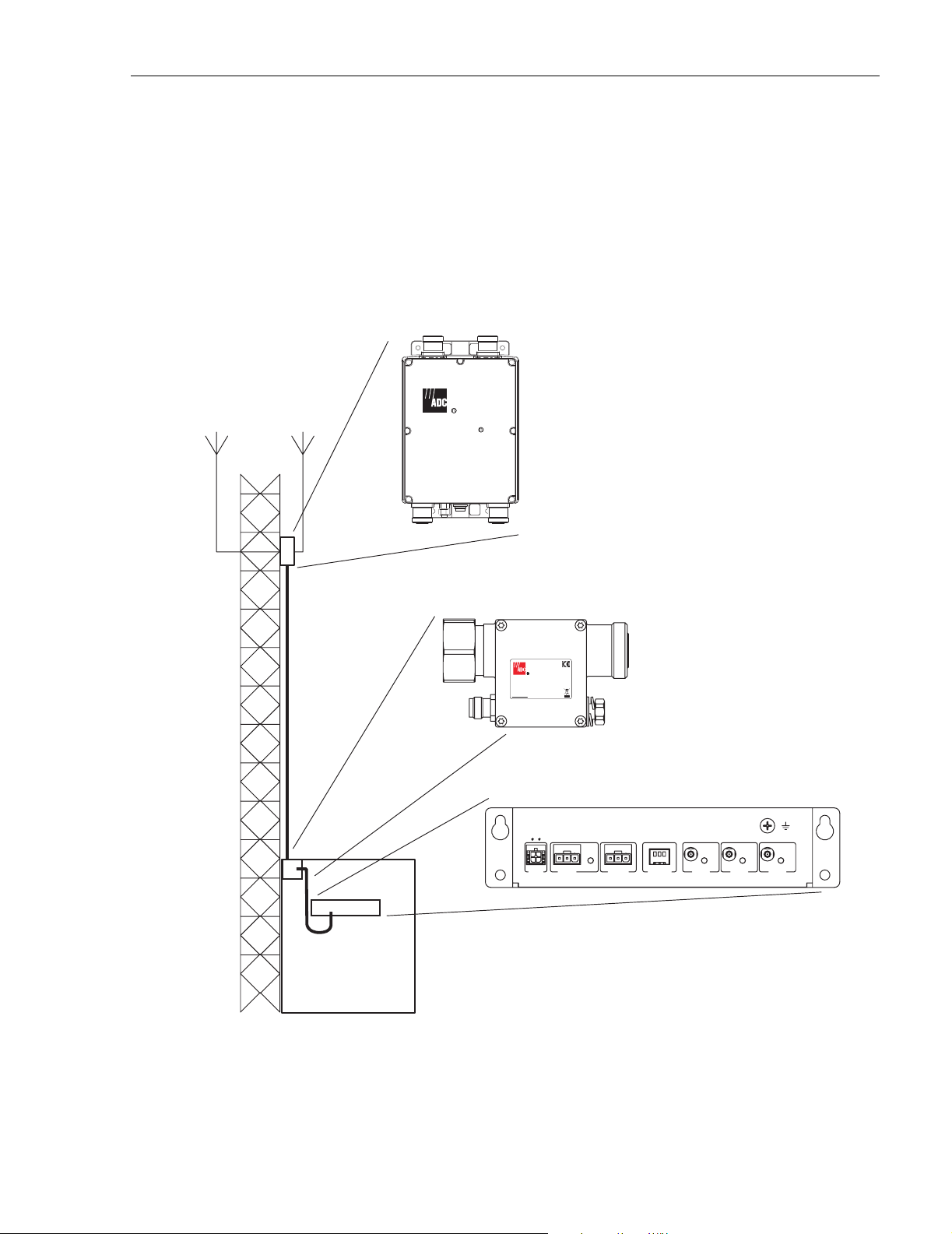
The ClearGain 1800 or 2100 MHz Dual Inline Tower Mounted Amplifier (TMA) system are
composed of some combination of three functional components: a ClearGain Power Distribution
Unit (PDU), a Masthead Unit (MHU) / Tower Mounted Amplifier (TMA), and a Bias-T.
shows where these components are located in a typical application on a communications tower.
ADCP-75-214 • Issue 2 • September 2006
Figure 1
MASTHEAD UNIT (MHU)
ClearGain
DUAL
INLINE
BIAS-T
BTS ANT
Bias-T kit
Freq: 800 - 2200MHz
Temp: -40 to +65 C
ASSEMBLED IN
Input: 5 to 24VDC
KOREA
Max Current: 2A
Date: YYYY/MM/DD
P/N: 1344027
S/N: XXXXXXXXX
DC
ClearGain PDU
G
W
R
B
- +
INPUT
NO COM NC FAIL
ALARM
RS485
BG
A
MHU
CONNECT
BASE
TRANSCEIVER
STATION
Figure 1. Functional Components of a ClearGain TMA System
OK OK OK
MHU 1 MHU 2 MHU 3
21297-B
One PDU may support up to three dual inline MHUs of the same frequency. Each MHU requires
a separate Bias-T. The ClearGain TMA system also includes power cables and alarm cables.
© 2006, ADC Telecommunications, Inc.
Page 1
Page 8
ADCP-75-214 • Issue 2 • September 2006
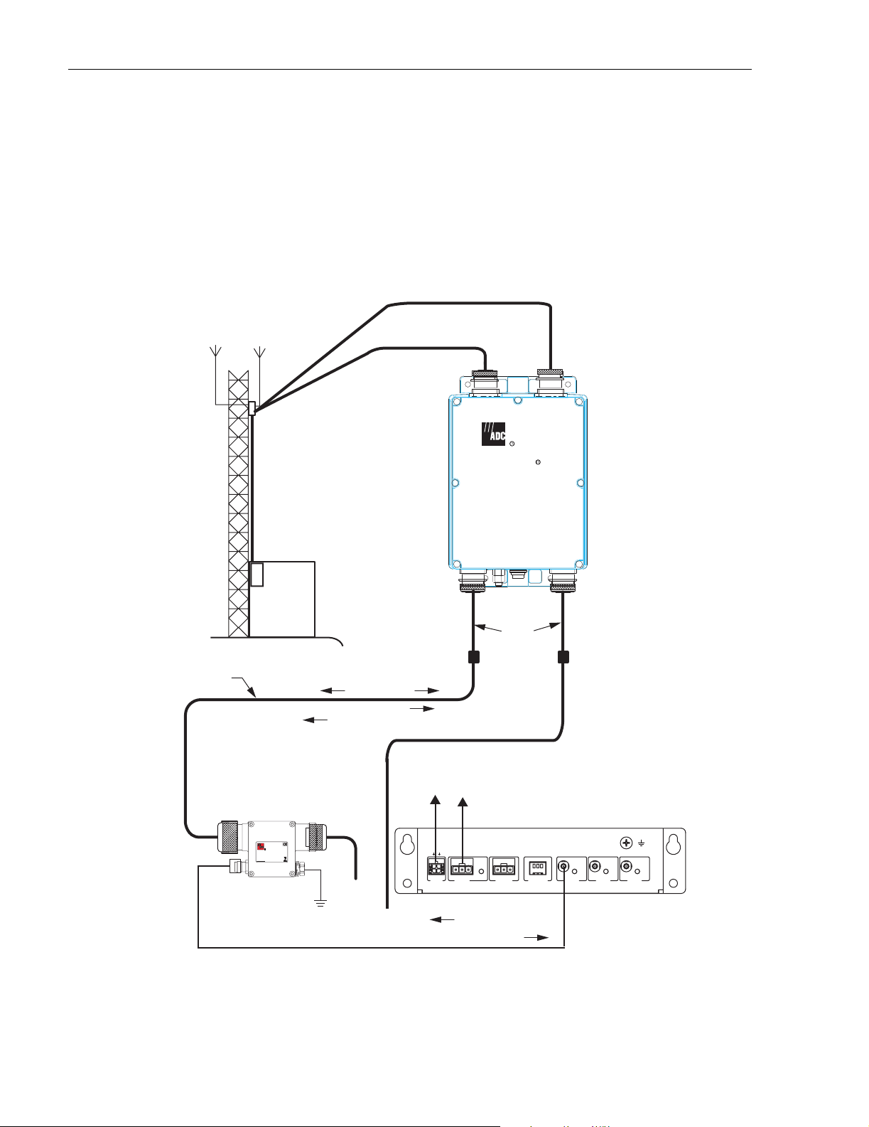
1.2 Functional Description
The basic purpose of a ClearGain Dual Inline TMA system is to amplify the uplink signal just
after the antenna. This is done to compensate for the loss in signal strength that occurs in
passage of the signal through the coaxial cable to the Base Transceiver Station (BTS) at the base
of the tower. The ClearGain TMA system improves the performance of the BTS by providing
12dB of uplink (reverse path) gain with a low noise figure. The ClearGain TMA system
provides visual and dry contact output alarming and lightning protection. Figure 2 depicts how
the system components are involved in system function.
COAXIAL
CABLE
ANTENNA
STATION
BASE
COAXIAL CABLE
TO ANTENNA
RF SIGNALS
DC POWER
FAULT DETECTION
ANT A
BTS A
JUMPER
CABLES
ANT B
ClearGain
MHU
BTS B
Page 2
© 2006, ADC Telecommunications, Inc.
BTS ANT
Bias-T kit
Freq: 800 - 2200MHz
Temp: -40 to +65 C
ASSEMBLED IN
Input: 5 to 24VDC
KOREA
Max Current: 2A
Date: YYYY/MM/DD
P/N: 1344027
S/N: XXXXXXXXX
DC
GROUND
INPUT
G
B
- +
W
R
SITE
ALARM
NO COM NC FAIL
ALARM
POWER
RX/TX (A)
RX/TX (B)
DC POWER
FAULT DETECTION
Figure 2. System Function
ClearGain PDU
ABG
RS485 MHU 1 MHU 2 MHU 3
CONNECT
OK OK OK
MHU
21305-B
Page 9

ADCP-75-214 • Issue 2 • September 2006
MHU – located as close to the antenna as possible, performs the amplifier function on the
uplink signal. Three subcomponents of the MHU, two RF cavity filters, and a Low Noise
Amplifier (LNA), are involved in the amplifier function. Downlink signal is not amplified but
passed through an RF cavity filter.
PDU
– located in the base station, provides DC current to power the LNAs and On/Off Key (OOK)
modem signal for use in the Remote Electrical Tilt (RET). The PDU outputs the DC current through
a front port from which it travels by way of a short linkage cable to the Bias-T. The injection of the
DC power onto the coaxial cable will not cause interference with signal transmission.
The PDU monitors the MHUs simultaneously by sensing their current draws. If any of the
MHUs fail, or if there is a cut or short circuit in the coaxial cable, the PDU sends an alarm to the
BTS. The PDU thus also monitors the condition of the coaxial cable, not just the MHU. The
PDU also has built-in lightning protection.
The PDU has a connector for RET communication with the BTS. The data bus is a two-wire bidirectional configuration and can be used for RS-485 communications link between the BTS
and PDU. The OOK modem is AISG standard compliant.
Bias-T – located on the coaxial cable, is a passive device that physically injects DC power onto
the coaxial cable to provide powering for the MHU. Bias-T may be installed indoors or
outdoors. There are four Bias-T connector options:
• 7/16 DIN male to the BTS; 7/16 DIN female to the ANT
• 7/16 DIN female to the BTS; 7/16 DIN male to the ANT
• N male to the BTS; N female to the ANT
• N female to the BTS; N male to the ANT
A single PDU supports three dual inline MHUs (with one Bias-T required for each dual inline
MHU). The Bias-T may be plugged into either of the RF cables to power the MHU.
2 SYSTEM INSTALLATION
2.1 Installation Overview
Installation consists of three main steps:
1. Installing the MHU: mechanical attachment, coaxial cables and ground cable.
2. Installing the PDU: mechanical attachment, operation power, alarms and ground cable.
3. Installing the Bias-T: mechanical attachment, coaxial cables, power cable and ground cable.
2.2 Masthead Unit Installation
Pole mounting kits are provided for installing the MHU. See Figure 3. Before any installation,
check that the ClearGain MHU has no visible damages or defects. Place ClearGain MHU as
close to the antenna as possible.
© 2006, ADC Telecommunications, Inc.
Page 3
Page 10

ADCP-75-214 • Issue 2 • September 2006
Note: All hardware is specified in metric units. The threads are sensitive to damage.
Figure 3. Typical MHU Clamp Mounting Kit Components
1. When installing on a pole a clamp kit (Figure 3) is required. The kit is designed for tube
diameters of 30 to 140 mm.
2. Before going up to the mast, temporarily remove the connector protector plugs, inspect the
7/16 DIN connectors for damage, and return the connector protector plugs to their
respective connectors.
3. Install clamps on pole and route through the mounting openings near the center of the MHU.
4. Position MHU at the desired location and tighten clamps securely.
2.2.1 Installing the MHU Ground Cable
Good grounding of the ClearGain MHU is important to protect the unit against voltage surges.
These surges may be caused by lightning or inadvertent contact with high voltage power lines.
Install the ground cable as follows:
1. Connect the ground cable to MHU bottom using M8 star washer and nut.
2. Connect the other end of the cable to a good ground (site ground) with a reliable joint.
Page 4
© 2006, ADC Telecommunications, Inc.
Page 11

ADCP-75-214 • Issue 2 • September 2006
GROUNDING and BONDING CONSIDERATIONS
• Grounding is very important in tower top applications. Shipped with each MHU, is a 4mm
(#6 AWG), one-meter (39-inch) ground cable with single hole crimp lug connectors on
both ends. Installation hardware is provided to attach one end to the MHU.
• Keep ground wire as short and direct (no loops or knots) as possible, secure it to a good
ground point (metal to metal).
• Always follow local grounding practices. The single hole lug is typically used to attach a
dedicated tower ground bus.
• In the absence of a dedicated ground, the tower structure itself can be used by using a
exothermic weld joint (not very common) or a mechanical ground clamp. If a clamp is
used, it must be very tight and protected from corrosion effects with a corrosion
preventative compound. It is recommended that the ground integrity/resistance at any
mechanical junction be checked during periods of regular tower maintenance. Always
follow local grounding practices.
• If the ground cable length is too short, customer may make a longer ground cable using
4mm (#6 AWG) wire as long as all the mechanical connections are tight and clean. Keep
ground cables as short as possible.
2.2.2 Installing Coaxial Cables
Caution: Before connecting any coaxial cables, ensure that the BTS transmitter output is
turned off and that precautions are taken to ensure that the transmitter cannot be activated
during the equipment installation.
Four short coaxial jumpers should be pre-made. Two will connect the BTS ports to the hard line
and the other two will connect the ANT ports to the antenna.
Caution: Remote Electrical Tilt (RET) connector on MHU must be covered with protective cap
if a cable is not connected to meet IP65 rating.
Most installations require four good quality flexible coax jumpers, normally terminated with 7/16
DIN-7/16 DIN connectors. Check gender of hard line and determine if antenna pigtail is present,
adjust accordingly for a correct match.
The coaxial feeder that runs from the base station to the antenna should be attached to the BTS
port of the MHU using a jumper cable. The reason for the jumper cable is to ensure that
mechanical forces caused by temperature change will not damage the MHU connectors. Tighten
connectors to 25–30 Nm (18.43–22.13 ft. lbs.) torque.
To improve connection reliability the connector joint can be protected. This is done, by
installing specific weatherproof tape over the cable connectors. Loose cable should be secured
to the tower using cable brackets.
© 2006, ADC Telecommunications, Inc.
Page 5
Page 12
ADCP-75-214 • Issue 2 • September 2006
2.3 PDU Installation
2.3.1 Mechanical Attachment of PDU
Warn ing: Never install the Power Distribution Unit in a wet location or during a lightning
storm. When installing or modifying communication lines, disconnect lines at the interface
before working with uninsulated lines or terminals to prevent electrical shock.
The PDU should be mounted in accordance with local code using appropriate hardware. The
PDU has two mounting holes on either side, as shown in Figure 4. Below are guidelines for
standard wall mount, masonry wall mount, and rack mount of the PDU.
2.3.1.1 Standard Wall Mount
When mounting the PDU on a wooden or metal surface, it is recommended that it be installed
on a secure surface.
2.3.1.2 Masonry Wall Mount
When mounting the PDU on a masonry surface, it is important that the bolts (especially the
upper bolts) be located as close as possible to the center of bricks or blocks. Masonry mounting
screws are not provided.
Page 6
© 2006, ADC Telecommunications, Inc.
Figure 4. Example of PDU Standard Wall Mount
Page 13

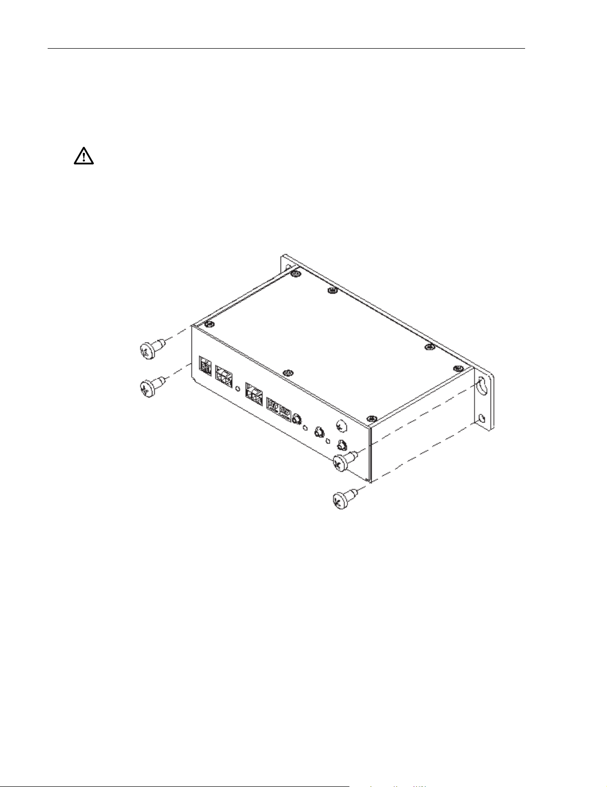
2.3.1.3 Rack Mount (Optional)
ADCP-75-214 • Issue 2 • September 2006
A mounting bracket, shown in
Figure 5
is available that allows the PDU to be mounted in a rack. If
mounting PDU in a rack, refer to the installation drawing provided with the mounting bracket
RACK
MOUNTING
BRACKET
21300-A
Figure 5. PDU Rack Mount Bracket
2.3.2 Installation of PDU Cables
.
There are fife PDU cables:
• Power cable
•Alarm cable
• Communication cables
• MHU (Bias-T) cables
• Ground cable.
© 2006, ADC Telecommunications, Inc.
Page 7
Page 14

ADCP-75-214 • Issue 2 • September 2006
Figure 6 shows the cable terminations on the front of the PDU. Connect the cables as follows:
(Left to Right: Power Cable, Alarm Cable, RS-485, Three MHU (Bias-T) Cables, and Ground Cable)
Figure 6. Cable Terminations on Front of PDU
1. Connect the ground cable under the grounding screw on the PDU front panel. Connect the
other end of the cable to the site-grounding pole.
2. Connect the alarm cable leads to the base station or site alarm system. Use either
“Normally Open” or “Normally Closed” contacts. Figure 7 shows the PDU alarm logic.
3. Connect the other end of the alarm cable to the PDU “ALARM” connector.
4. Connect communication cable leads to the base station or site control systems to control
RET. The data bus is a two-wire bi-directional configuration and is used for the RS-485
communications link. Figure 7 shows the RS-485 connection.
5. Connect the power cable to the site DC power source. (The power cable has four leads.
Red is positive, Black is negative, and White/Green is for ground.)
6. Connect the power cable to the “INPUT” connector on the PDU front panel.
Page 8
© 2006, ADC Telecommunications, Inc.
Page 15

DC
INPUT
POWER DISTRIBUTION UNIT
PDU
ALALRM
LOG IC
ADCP-75-214 • Issue 2 • September 2006
OUTPUT
21307-B
NO
(NO RM ALLY
OPEN)
COM
(CO MMO N)
NC
(NO R MA LLY
CLOSED)
GND
RS485A RS 485B
Figure 7. PDU Alarm Logic and RS-485 Connections
2.3.3 Setting the DIP Switch on the PDU
PDU has one set of dip switches to enable or disable the MHU ports. To disconnect unused MHU
output (see
Figure 8
). For the MHU outputs that are used, the DIP switch must be in the “down”
position or “ON”. Unused outputs must be disconnected by setting DIP switch in the “up” position.
(Switch 1 and 3 Set to “ON” to Indicate Use of MHU Ports 1 and 3)
Figure 8. Example of DIP Switch Setting on the PDU
© 2006, ADC Telecommunications, Inc.
Page 9
Page 16

ADCP-75-214 • Issue 2 • September 2006
2.4 Bias-T Installation
2.4.1 Mechanical Attachment and Cable Connections
Caution: Prior to installing any Bias-T unit, ensure that the BTS transmitter output is turned off
and that precautions are taken to ensure that the transmitter cannot be activated during the
equipment installation.
The Bias-T is installed either inline with the antenna feeder cable or directly to the BTS antenna
port. Integrated lightning protection is built into each Bias-T unit. There is no additional
mounting hardware required. Bias-T can be installed in either of the two antenna feeder cables
for each MHU. Connect the Bias-T as follows:
1. Connect the Bias-T “BTS” connector inline with the antenna feeder cable or directly in the
BTS antenna port.
Note: Orientation of the Bias-T is critical, BTS end should face the BTS and ANT should
face the antenna.
2. Connect the coaxial run going to the MHU to the “ANT” port of the Bias-T.
3. Connect the mini coax cable to the TNC connector of the Bias-T unit.
4. Connect the other end of the mini coax cable to the PDU front panel SMB connector
MHU1…3 (whichever is being used).
5. Connect the ground cable to the Bias-T ground terminal (see Figure 9).
6. Connect the other end of the ground cable to the site-grounding pole.
BTS ANT
Bias-T kit
Freq: 800 - 2200MHz
Temp: -40 to +65 C
ASSEMBLED IN
Input: 5 to 24VDC
KOREA
Max Current: 2A
Date: YYYY/MM/DD
P/N: 1344027
S/N: XXXXXXXXX
DC
GROUND TERMINAL
21298-A
Figure 9. Bias-T Ground Cable Connection
2.4.2 Additional Lightning Protection
ADC recommends that the operator install further lightning protection between the MHU and
Bias-T. It must allow the DC voltage to pass through the lightning protector, if it does not then
the Bias-T should be mounted on the antenna side of the protection.
Page 10
© 2006, ADC Telecommunications, Inc.
Page 17

3 TROUBLESHOOTING
When a fault occurs with the system, the red alarm LED on the PDU and the PDU dry-alarm
contact are activated. In such a case, troubleshoot for problems as follows:
1. Check that power is present at the PDU. The PDU will not operate if DC is not present,
polarity is incorrect, or the DC presented is out of specifications (–56 to –20 VDC or +20
to +56 VDC).
2. Each MHU output has a status LED. Status LED for each MHU that is in use should be
GREEN.
3. Disable or disconnect any unused MHU ports to prevent false alarm conditions.
4. Verify that DC voltage is present at the MHU port on the PDU. Disconnect the MHU
(Bias-T) cable and measure output voltage using a multimeter (Voltage measurement,
DC). Nominal DC output power should be 14–16 VDC.
5. Verify that DC voltage is present at the antenna side of the Bias-T. Disable RF transmit
power or disconnect it from the BTS. Disconnect antenna feeder cable from ANT side of
Bias-T and measure voltage using a multimeter (Voltage measurement, DC). Nominal DC
output power should be 14–16 VDC.
ADCP-75-214 • Issue 2 • September 2006
© 2006, ADC Telecommunications, Inc.
Page 11
Page 18

ADCP-75-214 • Issue 2 • September 2006
4 TROUBLESHOOTING 4-PORT CLEARGAIN DUAL INLINE DUAL DUPLEX
TOWER MOUNTED AMPLIFIERS
Trouble is visually indicated by LED's or no LED illumination on a specific MHU, swap Bias-T
cables on PDU ports to see if trouble remains or moves (reference Figure 8). See Figure 10 for
possible trouble points.
ANTENNA
JUMPER
FEEDLINE
JUMPERS
ANTENNA
JUMPER
MASTHEAD
UNIT (MHU)
NOTE: COMMON FAILURE
POINTS ARE THE ANTENNA
AND FEEDLINE JUMPERS/
CONNECTORS.
HARD LINE
SHELTER
TEST
POINT
CHECK IF EXTERNAL JUMPERS
OR SURGE PROTECTORS ARE PRESENT.
IF A SURGE PROTECTOR IS ANYWHERE
BETWEEN THE BIAS-T AND THE MHU
IT MUST BE ABLE TO PASS DC.
Figure 10. Tower Mounted Amplifiers
HARD LINE
21299-A
Page 12
© 2006, ADC Telecommunications, Inc.
Page 19

4.1 Troubleshooting
1. Observe and record PDU LED status. Disable or disconnect RF from BTS. Remove any surge
protectors. Disconnect Bias-T from the antenna feedline / hardline / jumper / protector.
2. Multimeter checks:
a. Measure voltage on the Bias-T _______ VDC. Normal is 15 VDC.
ADCP-75-214 • Issue 2 • September 2006
FEED LINE
PDU
PDU
b. Measure resistance of the feedline _______ Ohms. Normal is High or Very high Ω
(KΩ/ΜΩ).
FEED LINE
3. Antenna/cable analyzer checks. Measure the in-band RL/VSWR of the system ______ dB
or ratio. Check distance to Fault for anomalies.
© 2006, ADC Telecommunications, Inc.
Page 13
Page 20

ADCP-75-214 • Issue 2 • September 2006
4. Re-connect Bias-T with a T adapter. Verify voltage on the T adapter _______ VDC.
Normal is 15 VDC.
PDU
5. Re-connect to original configuration and return to service. PDU should illuminate a green
LED for each active TMA if there are no faults in the system.
6. Check with operators for improved performance.
4.2 Troubleshooting Hints
• If voltage is outside of the normal range, trace it back towards the fault.
• If no resistance or low resistance, check protector, feedline, jumpers and MHU.
• If an infinite resistance reading (sometimes indicated by OL), check to see if MHU is
installed or for a discontinuity exists up to the MHU.
• Normal in-band RL should be greater than 18dB. If less than 18dB, check protector,
feedline, jumpers and antenna.
• Mark receive and transmit bands to verify correct filtering.
• Check the distance to fault to identify any anomalies on the feedline.
Page 14
© 2006, ADC Telecommunications, Inc.
Page 21

4.3 Troubleshooting Flowchart (For Systems With Three-Port MHUs)
If directed by the flowchart, refer to the troubleshooting matrix in Section 4.4 or to the return
loss sweep guide in Section 4.5.
START
• CHECK SUPPLY IS -56 to -20 VDC or +20 to +56 VDC.
ANY
LIGHTS ON
THE PDU?
YES
NO
The red lead is connected to the higher potential.
• CHECK SUPPLY FUSE/BREAKER IS OK. (5A RATING)
• CHECK DC CABLE AND CONNECTION.PROBLEM
The red Fail led should come on when any MHU
select dip switch is pushed to the down position. If
the bias-t connection is not made.
ADCP-75-214 • Issue 2 • September 2006
OFF
PDU OR
CONNECTIVITY
PROBLEM
RED
MHU
led
YELLOW
SOLID
ONE
PAT H
FAILING
REFER TO TROUBLESHOOTING MATRIX
ALARM
led
OFF
MHU
led
GREEN
TTA ACTIVE
The red Alarm led should come on
when any MHU select dip switch
OFF
is pushed to the down position. If
the bias-t connection is not made.
• CHECK DC CONNECTIVITY
TO THE
• CHECK MHU PORT FOR 18VDC.
IF NOT PRESENT, REPLACE PDU.
• CHECK BIAS-T CABLE FOR
18VDC. IF NOT
PRESENT,
REPLACE BIAS-T CABLE.
• CHECK BIAS-T FOR 18VDC.
IF NOT
PRESENT, REPLACE BIAS-T.
• CHECK RESISTANCE OF
FEEDLINE.
- LO OHMS OR
SHORTED;
PROBLEM TOP SIDE.
- HI OHMS OR OPEN IS
NORMAL
BUT ALSO MAY INDICATE A
DISCONTINUITY.
21401-A
Page 15
© 2006, ADC Telecommunications, Inc.
Page 22

ADCP-75-214 • Issue 2 • September 2006
4.4 Troubleshooting Matrix
If directed in Section 4.3 to consult a troubleshooting matrix, see Tab le 1 below.
Note: ClearGain PDU DIP switches must be in the down position for each active MHU!
Note:
ClearGain PDU input voltage must be in the range –56 to –20 VDC or +20 to +56 VDC.
Table 1. Troubleshooting Matrix
PARAMETER SPECIFICATION EXPLANATION
GREEN/YELLOW
OK LED
RED GENERAL
ALARM LED
Electronic Load
Each Path OFF < 180 mA Fail OFF ON
Each Path ON 180 – 220 mA OK GREEN OFF
Total Fail 370 – 400 mA Fail OFF ON
Short Circuit
Protection
1.5 A ± 10% Fail GREEN ON
Short state of MHU path does not affect other path. After generating Green alarm,
the short state is held for ten seconds then Red alarm is generated by the PDU.
Circuit Fluctuation Min 180 mA
One path failed. YELLOW ON
Max 380 mA
Input Voltage
–56 to –20 VDC /
OK GREEN OFF
+20 to +56 VDC
Output Voltage 15 V, 4% Total failure. OFF ON
Page 16
© 2006, ADC Telecommunications, Inc.
Page 23

4.5 Return Loss Sweep Guide
RETURN LOSS SWEEP GUIDE FOR THE RECEIVE SECTION OF THE MHUs.
ADCP-75-214 • Issue 2 • September 2006
0
-5
-10
-15
-20
RL dB
-25
-30
-35
-40
-45
NORMAL IN-SYSTEM SWEEP. TYPICAL. DEGRADATION FROM NORMAL SYSTEM SWEEP.
GOOD BAD
v1 v2 v1 v2
RL IS STILL GOOD IN RX BAND.
RECOMMEND CONNECTOR/LINE/ANTENNA CHECKS
DURING NEXT SCHEDULED MAINTENANCE PERIOD WHEN
TOWER CREW AVAILABLE.
RESISTANCE LOOKING INTO THE FEEDLINE SHOULD INDICATE HIGH OR INFINITE OHMS.
0
GOOD BAD
-5
-10
-15
-20
RL dB
-25
-30
-35
-40
-45
v1 v2 v1 v2
ANTENNA PORT: TERMINATED WITH 50 OHM LOAD.
"PERFECT ANTENNA" < 50 OHM LOAD >
ANTENNA PORT: ANTENNA CATASTROPHICALLY
FAILED "OPEN".
ANTENNA PORT: ANTENNA CATASTROPHICALLY
FUSED "SHORT".
18270-A
© 2006, ADC Telecommunications, Inc.
Page 17
Page 24

ADCP-75-214 • Issue 2 • September 2006
5 SPECIFICATIONS
5.1 1800 Masthead Unit
Tab le 2 provides typical specifications for the 1800 Masthead Unit.
CATEGORY PARAMETER SPECIFICATION
Filters RX (up link) frequency range 1710–1785 MHz
LNA with filter Gain 12 ± 1 dB
Table 2. 1800 Masthead Unit Specifications
TX (down link) frequency range 1805–1880 MHz
Tx path Insertion Loss 0.7 dB
Power Handling Capability 200W
Return Loss 18 dB
Noise Figure < 1.6 dB
IIP3 > + 13 dBm
Bypass Loss < 2.0 dB
Physical Dimensions (W x H x D) 189.0 x 336.0 x 90.0 mm
(7.4 x 13.2 x 3.5 inches)
Weight 6.9 kg (15.2 lbs.)
Color Gray Metallic
Connectors Antenna Connector 7/16 DIN Female
BTS Connector 7/16 DIN Female
Intermodulation Intermodulation < –115dBm (2x20W)
Power Operation Voltage 15 VDC
Operation Current 220 mA
Environmental Operating Temperature –40°C to +65°C (–40°F to +149°F)
Outdoor Protection IP65
Quality MTBF >500,000 hours
Lightning Protection IEC 61000-4-5
Page 18
© 2006, ADC Telecommunications, Inc.
Page 25

5.2 2100 Masthead Unit
Tab le 3 provides typical specifications for the 2100 Masthead Unit.
CATEGORY PARAMETER SPECIFICATION
Filters RX (up link) frequency range 1920–1980 MHz
LNA with filter Gain 12 ± 1 dB
Physical Dimensions (W x H x D) 166.0 x 210.0 x 80.0 mm
ADCP-75-214 • Issue 2 • September 2006
Table 3. 2100 Masthead Unit Specifications
TX (down link) frequency range 2110–2170 MHz
Tx path Insertion Loss 0.5 dB
Power Handling Capability 200W
Return Loss 18 dB
Noise Figure < 1.7 dB
IIP3 > + 13 dBm
Bypass Loss < 2.0 dB
(6.5 x 8.3 x 3.2 inches)
Weight 4.2 kg (9.3 lbs.)
Color Gray Metallic
Connectors Antenna Connector 7/16 DIN Female
BTS Connector 7/16 DIN Female
Intermodulation Intermodulation < –106dBm (2x20W)
Power Operation Voltage 15 VDC
Operation Current 220 mA
Environmental Operating Temperature –40°C to +65°C (–40°F to +149°F)
Outdoor Protection IP65
Quality MTBF >500,000 hours
Lightning Protection IEC 61000-4-5
© 2006, ADC Telecommunications, Inc.
Page 19
Page 26

ADCP-75-214 • Issue 2 • September 2006
5.3 PDU (Power Distribution Unit)
Tab le 4 provides typical specifications for the PDU.
Table 4. Power Distribution Unit (PDU) Specifications
CATEGORY PARAMETER SPECIFICATION
Electrical Input voltage range 20–56VDC positive/negative ground
Output voltage 15V, 4% (Over voltage protection)
Output voltage accuracy 4% in 20mA – 400mAMAX 10% in 1.5A
Output ripple 100mV pk – pk
PDU Inrush Current ETS300132-2, Part 2
Short circuit protection 1500mA, 10%
(Input polarization protected)
Connector and
LED
Outputs for TMA's SMB connector Male (3 pcs)
Input connector Molex Micro-fit 43045 - 0400
General alarm connector Molex Mini-Fit 39-30-3035
Communications link between BTS
Molex Mini-Fit 39-30-3035
and RET
Indicators Two color LED (3 pcs) (green and yellow)
Red LED 1 pcs
Physical Dimensions (W x H x D) 194.4 x 43.6 x 100.0 mm
(7.7 x 1.7 x 3.9 inches)
Weight 0.5 Kg (1.2 lbs.)
Color Gray Metallic
Communication Pin Number Signal Comments
1 RS485 A RET control command AISG Layer2. ISO/
IEC 8482:1993 (RS485).
2RS485 B
3 RS485 GND
PDU only receives control command from BTS and modulates 2.176MHz Modem
Signal and transmit to TMA through SMB connector, and vice versa.
Resistance between RS485 A and
> 1k Ohm
RS485 B
Resistance between RS485 A or
> 1k Ohm
RS485 B and DC return / RS485 GND
Page 20
© 2006, ADC Telecommunications, Inc.
Capacitance between RS485 A or
RS485 B
Capacitance between RS485 A or
RS485 B and DC/RS485 GND
< 1nF
< 1nF
Page 27

5.4 Bias-T
ADCP-75-214 • Issue 2 • September 2006
Tab le 5 provides typical specifications for the Bias-T.
Table 5. Bias-T Specification
CATEGORY PARAMETER SPECIFICATION
RF Path Frequency Rangy (MHz) 800–2200
Insertion Loss (max) 0.2 dB
Return Loss (min) 19 dB
Power Handling (max) 500W RMS
Isolation (RF to DC port) > 30 dB
Inter modulation (3rd order) 2x20W tones <–108 dBm
DC Path DC Input Voltage 5–24 V
Input Current 0–2 A
DC Path Resistance < 1 Ohm
Physical Dimension (HxWxD) mm 55.5 x 95.0 x 40.0mm
(2.2 x 3.7 x 1.6 inches)
Weight 0.3 Kg (0.7 lbs.)
Color Gray Metallic
Housing Aluminum
Environmental Operating Temperature –40 to +65º C (–40°F to +149°F)
Storage Temperature –40 to +70º C (–40°F to +158°F)
Outdoor Protection IP65
Quality MTBF 500,000 hours
Lightning
Protection
Current Peak 10 KA
Raising Time (10–90) 8 ns
Peak Half Voltage Time 50–50) 20 ns
© 2006, ADC Telecommunications, Inc.
Page 21
Page 28

ADCP-75-214 • Issue 2 • September 2006
6 CUSTOMER INFORMATION AND ASSISTANCE
PHONE:
U.S.A. OR CANADA
Sales: 1-800-366-3891 Extension 73000
Technical Assistance: 1-800-366-3891
Connectivity Extension 73475
Wireless Extension 73476
EUROPE
Sales Administration: +32-2-712-65 00
Technical Assistance: +32-2-712-65 42
EUROPEAN TOLL FREE NUMBERS
Germany:
UK:
Spain:
France:
Italy: 0800 782374
ASIA/PACIFIC
Sales Administration: +65-6294-9948
Technical Assistance: +65-6393-0739
ELSEWHERE
Sales Administration: +1-952-938-8080
Technical Assistance: +1-952-917-3475
WRITE:
ADC TELECOMMUNICATIONS, INC
PO BOX 1101,
MINNEAPOLIS, MN 55440-1101, USA
0180 2232923
0800 960236
900 983291
0800 914032
ADC TELECOMMUNICATIONS (S'PORE) PTE. LTD.
100 BEACH ROAD, #18-01, SHAW TOWERS.
SINGAPORE 189702.
ADC EUROPEAN CUSTOMER SERVICE, INC
BELGICASTRAAT 2,
1930 ZAVENTEM, BELGIUM
PRODUCT INFORMATION AND TECHNICAL ASSISTANCE:
connectivity.tac@adc.com
wireless.tac@adc.com
euro.tac@adc.com
asiapacific.tac@adc.com
Contents herein are current as of the date of publication. ADC reserves the right to change the contents without prior notice.
In no event shall ADC be liable for any damages resulting from loss of data, loss of use, or loss of profits and ADC further
disclaims any and all liability for indirect, incidental, special, consequential or other similar damages. This disclaimer of
liability applies to all products, publications and services during and after the warranty period. This publication may be
verified at any time by contacting ADC's Technical Assistance Center.
© 2006, ADC Telecommunications, Inc.
13944-M
All Rights Reserved
Page 22
 Loading...