

Page 1
USER MANUAL
E
T
H
E
R
N
E
T
1
B
0
R
B
I
D
a
G
s
E
e
T
LINK
Campus-REX RS Interface Card
Catalog Number: CAD1069I 5 I ssue 5
Page 2

Copyright
April, 2001
© 2001 ADC DSL Systems, Inc. All rights reserved.
Trademark Information
ADC and ADC Telecommunications are registered trademarks of ADC
Telecommunications, Inc.
Avidia is a registered trademark of ADC DSL Systems, Inc.
No right, license, or interest to such trademarks is granted hereunder, and you agree
that you shall assert no such right, license, or interest with respect to such trademarks.
All other product names mentioned in this document are used for identification
purposes only and may be trademarks or registered trademarks of their respe ctive
companies.
Information containe d in this document i s company private to ADC DSL Systems, Inc.,
and shall not be modified, used, copied, reprod uce d or disclosed in who le or in part
without the written consent of ADC.
Information furnished by ADC DSL Systems, Inc. is believed to be accurate and
reliable. However, no responsibility is assumed by ADC DSL Systems, Inc. for its use;
nor for any infringement of patents or other rights of third parties which may result
from its use. No license is granted by implication or ot herwise under any patent or
patent rights of ADC DSL Systems, Inc. ADC DSL Systems, Inc. reserves the right to
change specifications at any time without no tic e.
Disclaimer of Liability
Information contai ned in this documen t is company priva te to ADC DSL Systems, Inc.,
and shall not be modified, used, copied, reprod uce d or disclosed in who le or in part
without the written consent of ADC.
Contents herein are current as of the date of publ ication. ADC reserves the right to
change the contents without prior notice. In no event shall ADC be liable for any
damages resulting from loss of data, loss of use, or loss of profits, and ADC further
ii Campus-REX RS Interface Card User Manual
Page 3

FCC Notice
FCC NOTICE
This unit complies with the limits for a Class A digital device, pursuant to
Part 15 of the FCC rules. These limits are designed to provide reasonable
protection against harmful interference in a residential installation. This
equipment generates, uses and can radiate radio fr equency en ergy and, if not
installed and used in accordance with the instructions, may cause harmful
interference to radio communications. However, there is no guarantee that
interference will not occur in a particular installation. If this equipment does
cause harmful interference to radio or television reception, which can be
determined by turning the equipment off and on, the user is encouraged to try
to correct the situation by one or more of the following measures:
• Reorient or relocate the receiving antenna.
• Increase the separation between the equipment and the receiver.
• Consult the dealer or an experienced radio or television technician
for help.
Any changes or modifications not expressly approved by the grantee of this
device voids the user’s authority to operate the equipment.
Campus-REX RS Interface Card U ser Manual iii
Page 4
Using This Manual
USING THIS MANUAL
This manual documen ts the Camp us-REX® RS Interface Card (part number
150-1175-51). It includes information on how to:
™
• install the card in either a Campus-RS
Desktop Unit (150-1158-01,
150-1158- 02, 150-1158-51, or 150-1158-52) or Campus-S t ar
(150-1220-01, 150-12 20- 02, or 150-1220-51)
• configure the Campus-REX to operate as a bridge or a router
• monitor the Campus-REX
• contact ADC for assistance.
DOCUMENT CONVENTIONS
Two types of messages, identified by icons, appear in the text.
Notes contain information about special circumstances.
®
chassis
Cautions indicate the possibility of personal injury or
equipment damage.
This manual uses the following conventions:
• This font indicates text that appears on the LCD or terminal.
• Keycaps, such as , indicate keys that you press on a terminal
ESC
keyboard.
• Key names in bold font indicate buttons on the desktop unit or line unit
that you press.
For a list of abbreviations used in this manual, see “Abbreviations” on
page B-1.
iv Campus-REX RS Interface Card Use r Man ual
Page 5

Unpack and Inspect the Shi pm e n t
UNPACK AND INSPECT THE SHIPMENT
Upon receiving the Campus-REX RS Interface Card:
1 Unpack the card and inspect it for signs of damage. If it has been
damaged in transit, report the extent of the damage to the transportation
company and to your sales representative immediately. Order
replacement equipment if necessary.
2 Compare the contents of the package against the packing list to ensure a
complete and accurate shipment. If the shipment is incomplete or
incorrect, contact ADC as described in “Contacting ADC” on page D-1.
If you need to store the unit for several days or more before installing it, return
it to the original packaging.
Campus-REX RS Interface Card U ser Manual v
Page 6

Unpack and Inspect the Shipment
vi Campus-REX RS Interf ace Card User Manual
Page 7

Table of Contents
TABLE OF CONTENTS
Chapter 1: About the Product_________________________1-1
Product Features..................................................................................1-2
Compatibility with Earlier Campus Products......................................1-2
Compatibility with Campus-RS Products ............ ...............................1-4
Establishing an HDSL Link ................................................................1-5
Application..........................................................................................1-6
Point-to-Point LAN Extension..............................................1-6
LAN Connections Over a WAN...........................................1-7
LAN Extension in a Routed Environment............................1-8
Chapter 2: Installing the Campus-REX RS
Interface Card ____________________________2-1
Install the Card....................................................................................2-1
Installing into a Campus-RS Desktop Unit...........................2-2
Installing into a Campus-Star Chassis..................................2-3
Connect the Ethernet Line...................................................................2-4
Choosing the Cable...............................................................2-4
Connecting the Cable ............................................................2-6
Power Up and Check the Ethernet Line..............................................2-7
Chapter 3: Set Up the Campus-REX System_____________3-1
Set Up an ASCII Terminal..................................................................3-2
Connecting the ASCII Terminal to the Campus Unit...........3-3
Logging Onto the Terminal ..................................................3-5
Set the HDSL Operating Mode...........................................................3-7
Using the LCD......................................................................3-8
Campus-REX RS Interface Card U ser Manual v ii
Page 8

Table of Cont en t s
Standard HDSL Mode.............................................3-8
Extended HDSL Mode............................................3-9
AutoSync HDSL Mode.........................................3-10
Using an ASCII Terminal....................................................3-11
Standard HDSL Mode...........................................3-12
Extended HDSL Mode..........................................3-13
AutoSync HDSL Mode.........................................3-16
Configure the Campus-REX as a Bridge or Router...........................3-19
Configuring as a Bridge ......................................................3-19
From the LCD.......................................................3-20
From an ASCII Terminal......................................3-21
Configuring as a Router ......................................................3-23
Entering Port Addresses........................................3-26
Setting Up the IP Static Routing Table.................3-27
Set the Timing Source........................................................................3-29
Using the LCD.....................................................................3-30
Using an ASCII Terminal....................................................3-30
Chapter 4: Configuring and Monitoring
through the LCD _________________________ 4-1
Navigating the LCD Menus.................................................................4-2
Restoring the System to Default Values..............................................4-3
Configuring the Campus-REX as a Master or Slave Unit...................4-4
viii Campus-REX RS Interface Card User Manual
Page 9

Table of Contents
Viewing and Configuring Alarms.......................................................4-5
HDSL Alarms .......................................................................4-5
Viewing Current Alarms ........................................4-5
Configuring Alarm Thresholds...............................4-6
Viewing 24-Hour HDSL Alarm History................4-7
AutoSync Alarms..................................................................4-7
Viewing Current Alarms ........................................4-8
Configuring the Alarm ...........................................4-8
Local Alarms.........................................................................4-8
Viewing Current Alarms ........................................4-8
Configuring the Alarm ...........................................4-9
Remote Alarms .....................................................................4-9
Viewing Current Alarms ........................................4-9
Configuring the Alarm .........................................4-10
Configuring Loopbacks.....................................................................4-10
Initiating a Loopback..........................................................4-11
Clearing a Loopback..................................................... ......4-11
Setting the Loopback Timeout............................................ 4 -12
Viewing System Information ..................................... ..... ...... ............4-12
Viewing Status Information ....................................... .......................4-13
Ethernet Information...........................................................4 -13
HDSL Margin .....................................................................4-14
Port Statistics ................................................................ ......4-14
Chapter 5: Configuring with an ASCII Terminal_________5-1
Setting Up and Logging On to an ASCII Terminal.............................5-2
Logging Onto a Remote Campus Unit................................................5-3
Logging Off of a Campus Unit............................................................5-3
Campus-REX RS Interface Card U ser Manual ix
Page 10

Table of Cont en t s
Using the Terminal Menus ..................................................................5-4
Returning Configuration Options to Default Values...........................5-5
Configuring the Campus-REX for SNMP Management.....................5-6
Entering Required SNMP Parameters...................................5-8
Enabling Authentication Error Trap Generation...................5-9
Configuring Startup Parameters.........................................................5-10
Configuring the Campus-REX as a Master or Slave Unit.................5-12
Configuring Alarms...........................................................................5-15
Entering System Information.................................................... ...... ...5-1 7
Setting the Time and Date...................................................5-18
Setting a Password...............................................................5-19
Identifying the Unit and Circuit..........................................5-19
Configuring Loopbacks.....................................................................5-20
Initiating a Loopback...........................................................5-22
Clearing a Loopback ........................................................ ...5-2 2
Setting the Loopback Timeout............................................5-23
Updating the Campus-REX Firmware...............................................5-24
Chapter 6: Monitoring with an ASCII Terminal_________ 6-1
Monitoring HDSL Performance..........................................................6-2
24-Hour Performance History...............................................6-4
Seven-Day Performance History...........................................6-5
Viewing Local Alarm History.............................................................6-6
Viewing Ethernet Statistics................................................. ...... ...........6-8
Viewing Product Information............................................................ 6-1 0
x Campus-REX RS Interface Card User Manual
Page 11

Table of Contents
Chapter 7: Internetworking and Management
Overview ________________________________7-1
MAC-Level Bridging and Spanning Tree Protocol............................7-2
MAC-Level Bridging............................................................7-2
Spanning Tree.......................................................................7-2
Static IP Routing .................................................................................7-4
Campus-REX IP Addresses..................................................7-9
Management Protocols......................................................................7-11
SNMP..................................................................................7-11
Campus-REX SNMP Agent ...............................................7-12
MIB and Trap Support........................................................7-13
BOOTP ...............................................................................7-14
Encapsulation Protocols....................................................................7-15
Appendix A: Technical Reference _____________________ A-1
Specifications .....................................................................................A-1
Default Settings............. ..... ...... ....................................... ...................A-2
LCD Menu Reference ........................................................................A-3
ASCII Terminal Menu Reference......................................................A-5
Appendix B: Abbreviations __________________________ B-1
Appendix C: The Documentation Set __________________ C-1
Campus-REX RS Interface Card U ser Manual xi
Page 12

Table of Cont en t s
Appendix D: Contacting ADC ________________________D-1
Product Support..................................................................................D-1
Advance Replacement ........................................................................D-2
Billing .................................................................................................D-2
Index _____________________________________________ E-1
xii C am pus-REX RS Interface Card User Manual
Page 13

ABOUT THE PRODUCT
The Campus® Remote Ethernet eXpress (Campus-REX) RS Interface Card
installs into a:
®
• Campus-Star
Line Unit
• Standalone Campus-RS Desktop Unit
chassis, along with a Campus-RS™ (Rate Selectable)
1
This comprises half of a High-bit-rate Digital Subscriber Line (HDSL)
transmission system. When connected to another Campus-RS, Campus -T1
Campus-768
system can transport digitized voice, data, and v ideo signals over existing
copper wire at a number of different HDSL rates.
The Campus HDSL system provides a connection between geographically
distributed Ethernet Local Area Networks (LANs) in a campus environment.
To provide the connection, the Campus-REX performs transparent 802.3
MAC bridging or static IP routing over an HDSL line. You can use existing
telephone-grade copper wiring as the HDSL transmission medium.
®
, or Campus-E1® Desktop Unit or Line Unit, the Campus-RS
This version of the Campus-REX must be installed in a
Campus-RS or Campus-HRS Desktop Unit or with a
Campus-RS or Campus-HRS Line Unit. It cannot be installed
in an older Campus Desktop Unit or with an older Campus
Line Unit.
®
,
Campus-REX RS Interface Card U ser Manual 1-1
Page 14

About the Product
PRODUCT FEATURES
The Campus-REX provides complete main bridging tasks such as dynamic
address learning, forwarding, filtering, and hashing/buffer management.
Other features include:
• embedded Simple Network Management Protocol (SNMP) agent
• IEEE 802.1d transparent MAC level bridging with Spanning Tree
protocol s upport
• static IP Routing
• BOOTP for configuration of IP parameters
• HDLC (High-level Data Link Control) or PPP (Point-to-Point Protocol)
frame encapsulation options
• 10BASE-T port for connection to an 802.3 LAN
• console port for maintenance and management
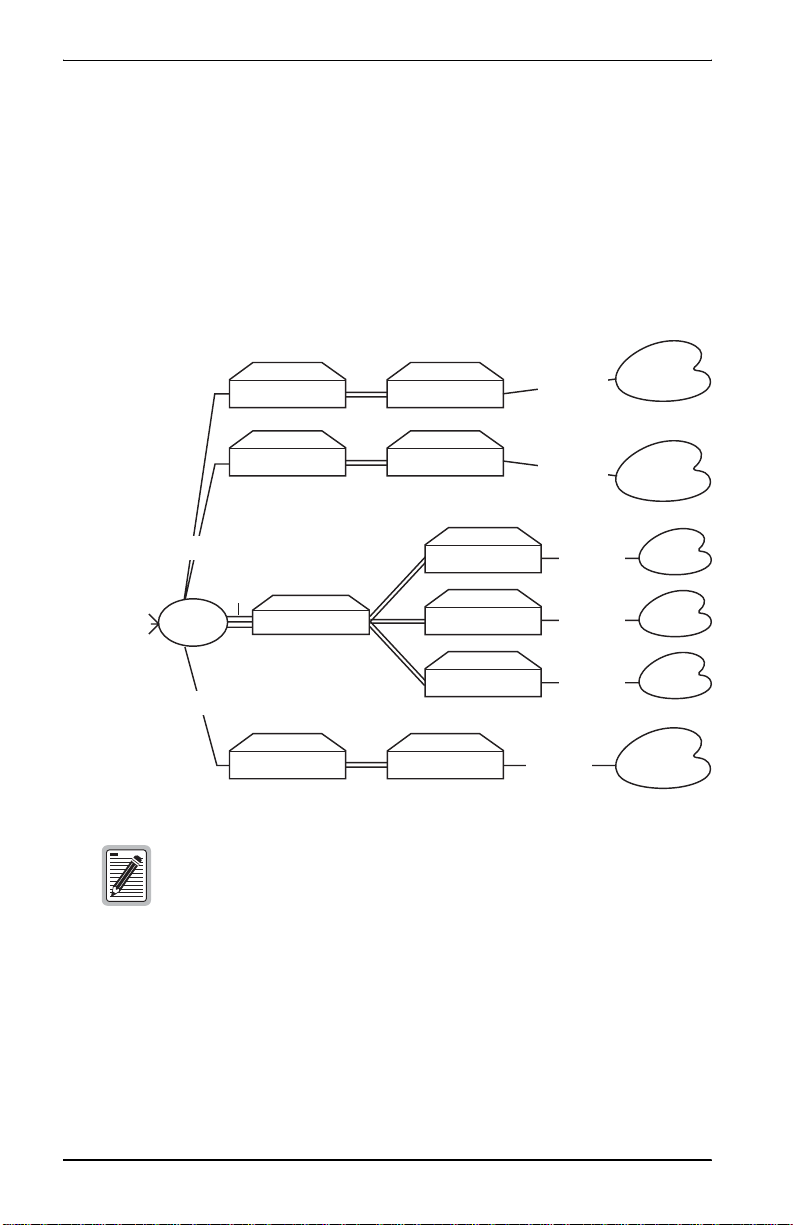
COMPATIBILITY WITH EARLIER CAMPUS
RODUCTS
P
When mated with a Campus-RS Desktop Unit or Campus-RS Line Unit, the
Campus-REX RS Interface Card is compatible, over the HDSL link, with
earlier versions of Campus products, such as the Campus-T1, Campus-E1,
and Campus-768, as shown in the following illustration. Campus-RS units are
not currently compatible with Campus-384 products.
Campus-T1, Campus-E1 or
Campus-RS
Campus-REX RS
Interface card
1-2 Campus-REX RS Interface Card User Manual
HDSL
Campus-768
Campus-REX T1,
Campus-REX E1, or
Campus-REX 768
Page 15

About the Product
All earlier versions of Campus products are manufactured to operate at a
single HDSL transmission rate, while the Campus-RS transmission rate is
user-selectable. To support compatibility with earlier Campus Products, the
following configuration options must be set on th e Cam pus-REX:
• Set the HDSL Operating Mode to Standard Mode.
• Set the Standard Mode HDSL Rate to T1, E1, or 768, to match the rate
of the earlier product.
If a Campus-RS unit is connected over an HDSL link to an earlier Campus
product, and if either unit has the HDSL Transceiver (XCVR) Mode set to
AUTO, the HDSL link may not operat e properly.
When operating the Campus-RS product with an earlier version of the
Campus products, to avoid any problems with link startup or operation, it is
recommended that the Transceiver Mode be set as follows:
• Campus-RS = MASTER
• Campus E1/T1/768 = SLAVE
If one or both units are already set to AUTO and the HDSL link is active,
disconnect the HDSL link, change the settings as recommended, and
reconnect the link. This will assure the link integrity on any subsequent
startups.
This situation does not apply to a circuit with two Campus-RS
units. You may leave the units set to their default setting of
AUTO, and they will operate properly.
For information on setting these options, see “Set the HDSL Operating
Mode” on page 3-7.
Campus-REX RS Interface Card U ser Manual 1-3
Page 16

About the Product
COMPATIBILITY WITH CAMPUS-RS PRODUCTS
The Campus-REX RS Interface Card is also compatible, over the HDSL link,
with another Campus-RS unit, as shown in the following illustr a tion.
Campus-RS Campus-RS
Campus-REX RS
Interface card
HDSL
When connecting to another Campus-RS Desktop Unit or Line Unit,
Standard Mode is still supported, providing access to HDSL transmission
rates of T1, E1 and 768 kbps. In addition, the Campus-RS system can be
configured to support an extended set of HDSL transmission rates, over either
one or two HDSL loops.
To support these additional transmission rates, set the followin g options on
the Campus-REX:
• Set the HDSL Operating Mode to Extended Mode or AutoSync Mode.
Campus-RS
Interface card
• Set the Extended Mode Loop Configuration to 1 Loop or 2 Loops,
depending on the physical layout of your HDSL network.
• Set the Extended Mode HDSL Rate to the desired setting.
1-4 Campus-REX RS Interface Card User Manual
Page 17

About the Product
The range of rates available for the HDSL Rate depends on the setting of
the Extended Mode Loop Configuration:
– 1 Loop HDSL Rate settings are between 128 kbps and 1.152 Mbps,
in 64 kbps increments
– 2 Loop HDSL Rate settings are between 256 kbps and 2.304 Mbps,
in 128 kbps increments
Not all of these modes and rates are available if the remote
Campus-RS system does not support them. Refer to the
remote interface card User Manual to see the HDSL modes
and rates supported by the card.
For information on setting these options, see “Set the HDSL Operating
Mode” on page 3-7.
ESTABLISHING AN HDSL LINK
Before an HDSL link can be established in Standard or Extended Mode, the
HDSL parameters for both the local and remote units must be set identically.
Using AutoSync Mode allows one unit to determine the HDSL parameters.
In AutoSync Mode, one unit is configured as a master and the other as a slave.
Upon startup, the HDSL parameters of the master unit are used to establish
the HDSL link. No further configuration of the slave unit is required.
If the remote unit is not configured as an AutoSync slave, an AutoSync
connection will not be established and the system generates an AutoSync
minor alarm. After several failed attempts, the master enters Fallback Mode
and attempts to establish a normal HDSL link with the same HDSL
parameters. If this is unsuccessful, for ex ample, if the slave un it is configured
to a different HDSL Rate, the master unit reverts to attempting to establish an
AutoSync connection.
Campus-REX RS Interface Card U ser Manual 1-5
Page 18
About the Product
APPLICATION
When installed in a Campus-RS Desktop Unit or Campus-Star chassis, the
Campus-REX functions as a remote bridge or static IP router.
You can use the Campus-REX to extend subnetworks to remote sites within
a campus. Or, for sites separated by greater distances, you can use the
Campus-REX to connect them through a public T1/E1 Wide Area Network
(WAN). See “Point-to-Point LAN Extension” and “LAN Connections Over
a WAN” on page 1-7 for more information.
Campus-REX software provides complete main bridging tasks of learnin g,
forwarding, filtering, and hashing/buffer management, 802.1d Spanning Tree
protocol, 802.3 drivers, packet sequencing, segmentation and reassembly,
and other local tasks. The Campus-REX is specifically designed for
10BASE-T LANs that use unshielded twisted pair (UTP) segments with
reach of more than 100 meters and that require low-cost, high performance
connectivity.
The Campus-REX performs full-bandwidth filtering on the 10BASE-T port,
and forwarding at the selected transmission rate.
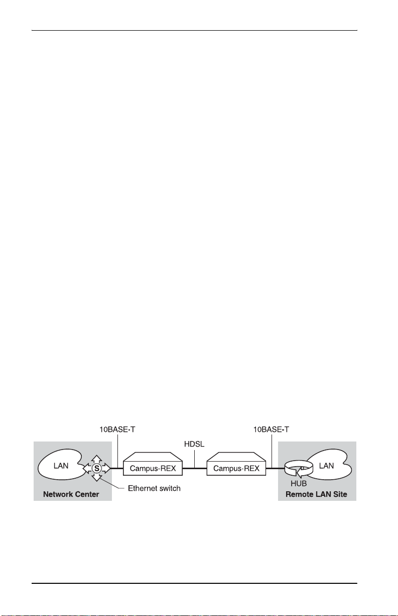
Point-to-Point LAN Extension
As organizations move or change, LANs also evolve and may become
fragmented or physically separated. The Campus-REX provid es a lower-cost
alternative to other LAN-extension solutions. The Campus-REX provides a
built-in 10BASE-T LAN interface that eliminates the need for other
internetworking devices while providing 30 times the performance of other
sub-rate wireless connectivity options, as shown in the followi ng figure.
1-6 Campus-REX RS Interface Card User Manual
Page 19

About the Product
LAN Connections Over a WAN
When LANs are distributed over a large physical area (such as within a
metropolitan area) or cabling is not available between sites, you can lease
appropriate unloaded copper pairs from a local carrier for LAN connectivity.
For transport over public networks, you can connect the public T1 network
(DSX-1 signal) to the LAN through Desktop Units with CSU/DSX-1
interface cards and the Campus-REX in a Desktop Unit. This app lication, as
shown in the following figure, simplifies access to public high-speed WANs
for LAN connectivity to remote sites.
PublicT1
Network
DSX-1
WAN
DSX-1
Campus-RS
Campus-RS
Campus-Star
Campus-T1
Campus-REX
Campus-REX
Campus-REX
Campus-REX
Campus-REX
Campus-REX
10BASE-T
10BASE-T
10BASE-T
10BASE-T
10BASE-T
10BASE-T
LAN
LAN
LAN
LAN
LAN
LAN
Campus-REX RS Interface Card U ser Manual 1-7
Page 20
About the Product
LAN Extension in a Routed Environment
The Campus-REX, set for bridging over PPP, can extend LAN access to a
centralized router. This application, as shown in the following figure, requires
two settings for the remote Campus-REX units:
• set the Bridge/Router mode to Bridge
• set the Encapsulation to PPP
External
network
connections
10BASE-T
10BASE-T
10BASE-T
10BASE-T
10BASE-T
10BASE-T
V.35
Router
V.35
Campus-RS Campus-REX
Campus-RS
V.35
Campus-Star
Campus-T1
Campus-REX
Campus-REX
Campus-REX
Campus-REX
Campus-REX
In this application, the router ports must be configured for
bridging with PPP encapsulation.
LAN
LAN
LAN
LAN
LAN
LAN
1-8 Campus-REX RS Interface Card User Manual
Page 21

INSTALLING
THE
CAMPUS-REX RS
INTERFACE CARD
You can mate the Campus-REX with either a Campus-RS Desktop Unit or a
Campus-RS Line Unit.
To Learn How to: See Page:
Install the Card 2-1
Connect the Ethernet Line 2-4
Power Up and Check the Ethernet Line 2-7
INSTALL THE CARD
The following sections describe how to install the Campus-REX RS Interface
Card.
Make sure you install the Campus-REX into a Campus-RS
Desktop Unit or into a Campus-Star chassis with a
Campus-RS Line Unit. The Campus-REX will not operate if it is
installed in an earlier version of these Campus products.
Ensure you read important information on surge protection
for HDSL line installation in the line unit or desktop unit
manual before installing the interface card.
2
Campus-REX RS Interface Card U ser Manual 2-1
Page 22
Installing the Campus-RE X RS Interface Card
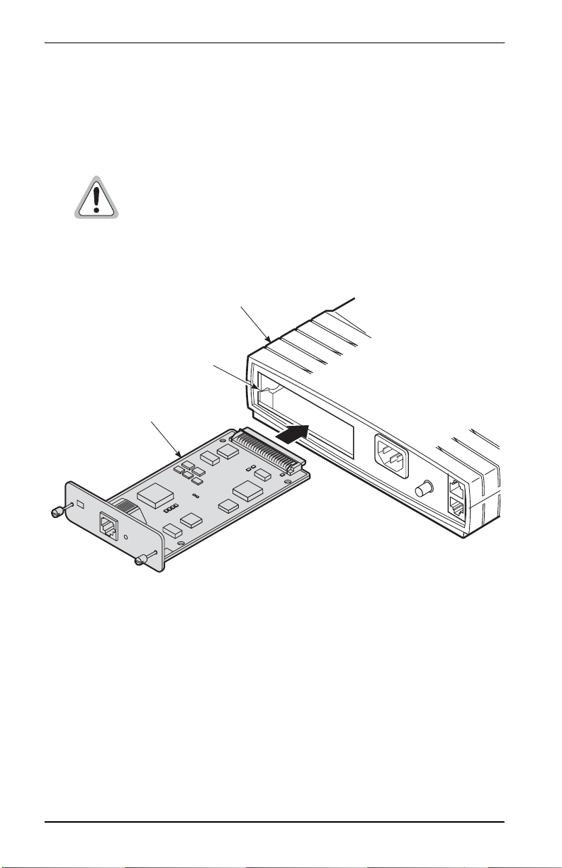
Installing into a Campus-RS Desktop Unit
This section describes how to install the Campus-REX into a Campus-RS
Desktop Unit.
Turn off the power on the Desktop Unit before you install the
card. Installing the car d with the power on m ay cause damag e
to the Desktop Unit, the card, or both.
1 Slide the card into the guide rails in the rear of the Desktop Unit.
Campus-RS Desktop Unit chassis
Guide rail
Campus-REX RS
Interface card
C
A
M
P
U
S
-
R
S
120VAC@60Hz
or 220VAC@50Hz
6
3
1
E
T
H
E
R
N
E
CFG
T
B
R
I
D
G
E
1
0
B
a
L
s
I
e
N
T
K
.2A Max
C
O
N
S
O
L
E
L
IN
E
2 Gently press the card into place until it is seated firmly in the mating
connector.
3 Use the two screws on the card to secure it into place.
4 To connect the Campus system to an HDSL line, see the Campus-RS
Desktop Unit User Manual.
2-2 Campus-REX RS Interface Card User Manual
Page 23
Installing the Campus-REX RS Interface Card
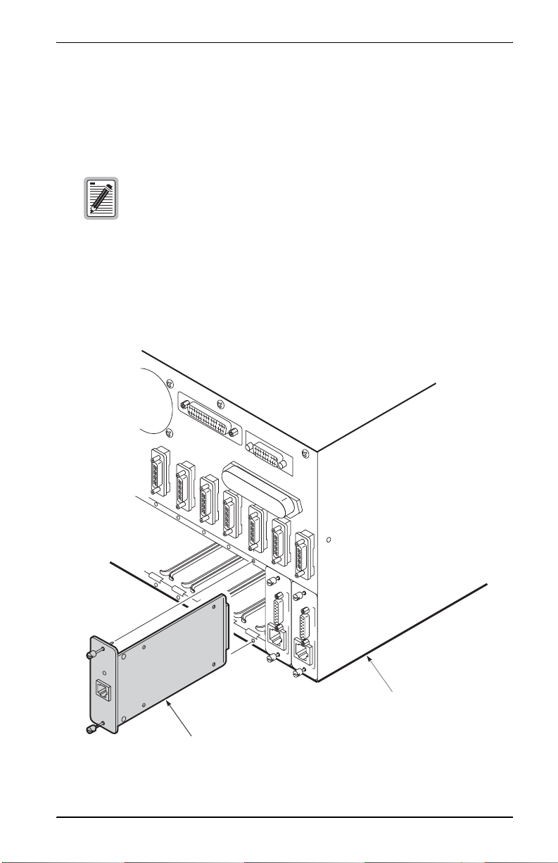
Installing into a Campus-Star Chassis
This section describes how to install the Campus-REX in a Campus- Star
chassis.
Before installing the Campus-REX, make sure there is not a
Line Unit installed in the corresponding slot on the front of the
Campus-Star chassis. The Campus-REX is not
hot-swappable. Installing the Campus-REX with a
corresponding Line Unit installed may cause damage to the
Campus-REX, the Line Unit, or both.
1 Slide the card into the guide rails in the desired slot on the rear of the
Campus-Star chassis.
DSX-1
-1/T
X
S
620
FG
D
C
DSX-1
X-1/T
S
G
620
F
D
C
Campus-Star
FG
C
chassis
Campus-REX RS Interface card
Campus-REX RS Interface Card U ser Manual 2-3
Page 24

Installing the Campus-RE X RS Interface Card
2 Gently press the card into place until it is seated firmly in the mating
connector.
3 Use the two screws on the card to secure it into place.
4 To install a Campus-RS Line Unit to work with the interface card, and to
connect the Campus system to an HDSL line, see the Campus-RS Line
Unit User Manual.
CONNECT THE ETHERNET LINE
The 10BASE-T MDI port on the rear of the Campus-R EX card co nnects the
Campus-REX to hubs, rep eaters, or other routers.
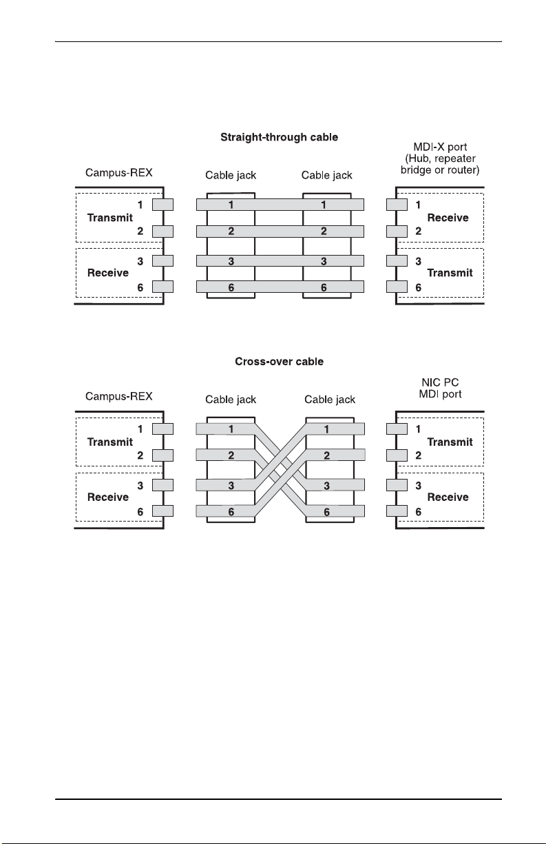
Choosing the Cable
Use a straight-through cable (Category 3 or better) to connect the card to a
device with an MDI-X port. Use a cross-over cable (Category 3 or better) to
connect the Campus-REX to a device with an MDI port.
The following table lists the 10BASE-T interface data signals for both MDI
and MDI-X port configurations.
(a)
MDI Pin
(a) A 10BASE-T port on a PC is always configured as an
MDI port.
2-4 Campus-REX RS Interface Card User Manual
MDI-X Pin Signal Description
1 3 TD+ Transmit Data (+)
2 6 TD- Transmit Data (-)
3 1 RD+ Receive Data (+)
4 4
5 5
6 2 RD- Receive Data (-)
7 7
8 8
Page 25
Installing the Campus-REX RS Interface Card
The following figures illustrate the signals f or straight-through and
cross-over cables.
Campus-REX RS Interface Card U ser Manual 2-5
Page 26
Installing the Campus-RE X RS Interface Card
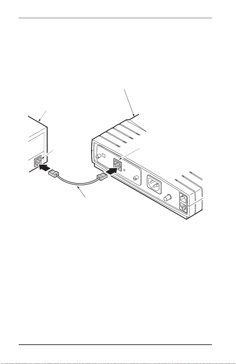
Connecting the Cable
To connect the 10BASE-T cable to the Campus-REX RS Interface Card:
1 Plug one end of the Category 3 cab le into the 10BASE-T MDI connecto r
on the rear of the Campus-REX.
Campus-RS Desktop Unit chassis
Local equipment
(Ethernet)
6
3
1
10BASE-T port
ETHERNET BRIDGE
C
F
G
10BaseT
10BASE-T MDI port
LIN
K
120VAC@60Hz
or 220VAC@50Hz
.2A Max
Category 3 cable
2 Connect the other end of the cable to your local equipment (repeater, PC,
or other 802.3 device).
2-6 Campus-REX RS Interface Card User Manual
Page 27

Installing the Campus-REX RS Interface Card
POWER UP AND CHECK THE ETHERNET LINE
1 Verify that the power cord is connected to the Desktop Unit or to the
Campus-Star chassis (if you have an AC power supply) and to an
external power source.
2 Do one of the following:
• If the Campus-REX is installed in a Desktop Unit, press the power
button on the back of the Desktop Unit.
• If the Campus-REX is installed in a Campus-Star, continue with
Step 3.
3 Verify that the Link LED on the Campus-REX card is green. This
indicates that the 10BASE-T connection is operating correctly. If the
Link LED does not light green, check the 10BASE-T cabling
configuration.
Campus-REX RS Interface Card U ser Manual 2-7
Page 28

Installing the Campus-RE X RS Interface Card
2-8 Campus-REX RS Interface Card User Manual
Page 29

SET UP THE
CAMPUS-REX SYSTEM
There are four sets of configuration op tions that must be set corr ectly fo r th e
Campus-REX to operate. With the default settings, the Campus-REX is set to
operate:
• with the HDSL Operating Mode set to Standard Mode
• with the Standard Mode HDSL Rate set to T1
• as a bridge, with the encapsulation format set to HDLC and Spanning
Tree protocol disabled
• with the Timing Source set to Internal
Dependin g on the requirements of your network, you may be able to use the
default settings for one or more of these options. If so, you can skip the
relevant section(s).
To Learn How to: See Page:
Set Up an ASCII Terminal 3-2
Set the HDSL Operating Mode 3-7
Configure the Campus-REX as a Bridge or Router 3-19
Set the Timing Source 3-29
3
Campus-REX RS Interface Card U ser Manual 3-1
Page 30

Set Up the Campus-REX System
SET UP AN ASCII TERMINAL
You can configure the Campus sys tem through a n ASCII terminal connected
to the Desktop Unit or Campus-Star in which the Campus-REX is installed.
The terminal provides access to some configuration options not available
through the LCD menus.
Depending on your immediate configuration plans, you may not need to set
up an ASCII terminal now. However, you need to set up a terminal if one of
the following applies:
• you plan to use the Campus-REX as a router
• you need to change the HDSL transmission rate and do not want to use
the LCD menus
• you plan on setting additional configuration options at this time
• you want to view performance statistics on the HDSL and 10BASE-T
interfaces
If none of these reasons apply to yo u, skip this section and proceed to “Set the
HDSL Operating Mode” on page 3-7.
3-2 Campus-REX RS Interface Card User Manual
Page 31

Set Up the Campus-REX System
Connecting the ASCII Terminal to the Campus Unit
To connect the Campus-REX RS Interface Card to an ASCII terminal:
1 Plug the console adapter into the standard 9-pin COM port on the ASCII
terminal and tighten the attached screws until they are snug. Skip this
step if the ASCII terminal provides an RJ-48 jack.
2 Plug one end of the console cable into the console adapter, then do one
of the following:
• Plug the other end of the console cable into the console port on the
Desktop Unit.
Campus desktop chassis
ASCII terminal
9-pin COM
port
G
E
LINK
Console port
120VAC@60Hz
or 220VAC@50Hz
.2A Max
E
T
H
E
R
N
E
T
10BaseT
B
R
I
D
Cable
Campus-REX RS Interface Card U ser Manual 3-3
Page 32

Set Up the Campus-REX System
• If the Campus-REX is installed in a Campus-Star, do one of the
following:
– plug the other end of the cons ole cable into the console port on
the front of the Line Unit.
Campus-Star chassis
C
M
U
-71
0
M
A
N
A
G
E
M
ASCII terminal
9-pin COM
port
P
O
W
Cam
LIN
HDSL
TEST
PORT
RS-232
CONSOLE
E
N
T
U
N
Campus HRS
LINE UNIT
HDSL
TEST
PORT
CONSOLE
IT
S
L
O
T
A
L
A
R
M
S
M
A
J
O
M
R
I
N
O
AC
R
O
R
E
Cam
LINE UNIT
HDSL
TEST
PORT
RS-232
CONSOLE
S
E
Cam
LINE UN
HDSL
TEST
PORT
RS-232
CONSOLE
T
pus HRS
IT
Cam
pus HRS
LINE UNIT
HDSL
TEST
PORT
RS-232
CONSOLE
pus HRS
RS-232
E
R
pus HR
E UNIT
S
Cam
LINE UNIT
HDSL
TEST
PORT
RS-232
CONSOLE
pus HRS
Cam
HDSL
TEST
PORT
CONSOLE
Console port
pus HR
LINE UN
S
IT
C
am
pus HRS
LINE
UNIT
Cam
LINE
HDSL
TEST
HDSL
PORT
TEST
RS-232
CONSOLE
PORT
RS-232
CONSOLE
RS-232
pus HR
U
S
NIT
Cable
– use an ad apter to plug the other end of the console cable into the
console port of the Campus Management Unit (CMU) on the
Campus-Star, as described in the Campus-Star User Manual.
3-4 Campus-REX RS Interface Card User Manual
Page 33

Set Up the Campus-REX System
3 Configure the ASCII terminal to the following communications settings:
• 9600 baud
• no parity
• 8 data bits
• 1 stop bit
• no hardware flow control
Logging Onto the Terminal
1 Press the on the ASCII terminal keyboard several times until
SPACEBAR
the baud rate is established and the Login Password screen displays on
the terminal monitor.
May 3,1999 ADC DSL SYSTEMS INC., CAMPUS RS, Version x.xx 13:12:59
Local Unit ID: Campus-REX Unit #34 Local I/F: REX
Remote Unit ID: Campus-REX Unit #12 Remote I/F: REX
Circuit ID: Network Extension Circuit 5001
LOGIN PASSWORD >
Campus-REX RS Interface Card U ser Manual 3-5
Page 34

Set Up the Campus-REX System
2 Press to log on. If you have set a password, type your password
ENTER
then press . The Main Menu displays.
May 3 1999 ADC DSL SYSTEMS INC., CAMPUS RS, Version x.xx 13:14:02
Local Unit ID: Campus-REX Unit #34 Local I/F: REX
Remote Unit ID: Campus-REX Unit #12 Remote I/F: REX
Circuit ID: Network Extension Circuit 5001
ENTER CHOICE>
ENTER
1) SYSTEM STATUS
2) DATA PORT SETTINGS
3) SYSTEM SETTINGS
4) DIAGNOSTICS
5) REMOTE LOGON
MAIN MENU
(L)ogout
If the system does not respond when you attempt to log on, ensure that
hardware flow control is turned off on the ASCII terminal.
3-6 Campus-REX RS Interface Card User Manual
Page 35

Set Up the Campus-REX System
SET THE HDSL OPERATING MODE
The Campus-REX is set to operate in Standard Mode with a T1 (1.544 Mbps)
HDSL Rate. This is compatible with other Campus-RS products and with
Campus-T1 Desktop Units and Line Units. If this is the desired setting fo r
your system, proceed to “Confi gure the Campus-REX as a Bridge or Router”
on page 3-19. Otherwise, follow the steps in this section to adjust the HDSL
transmission rate.
There are two ways to configure the HDSL line:
• To use the LCD menus, see “Using the LCD,” below.
• To use an ASCII Terminal, see “Using an ASCII Terminal” on
page 3-11.
Changes to the HDSL operating mode or transmission rate are
not automatically made to the remote unit. These changes
must be made at both the local and remote units for the HDSL
link to be re-established. If the remote unit is not easily
accessible, you can follow the instructions in “Logging Onto
a Remote Campus Unit” on page 5-3 to use an ASCII terminal
to perform a remote logon (if an HDSL link is up) and make the
desired change. When you change the HDSL settings for the
remote unit, the HDSL link is lost; it is re-established when
you make the identical change(s) to the local unit.
Campus-REX RS Interface Card U ser Manual 3-7
Page 36

Set Up the Campus-REX System
Using the LCD
The steps in this section use the menu buttons and LCD on the front of the
Desktop Unit or the Campus-Star Campus Management Unit (CMU). The
figure below shows the LCD and menu buttons on the Cam pus-RS Desktop
Unit. See the Campus-Star User Manual for the location of the LCD and
menu buttons on the CMU. For a complete description of how to use the menu
buttons and LCD, see “Navigating the LCD Menus” on page 4-2.
LCD Menu buttons
HDSL
Test
Port
CAMPUS RS
Next
Escape
Enter
To set the HDSL Transmission Rate:
1 Press Escape until Campus RS I/F: REX displays.
2 Press Next. HDSL LINK CONFIG & STATUS displays.
3 Press Enter. OPERATING MODE
displays.
4 Continue with one of th e fo llo win g sect ions , dep e nd ing o n w heth er you
are using Standard Mode (page 3-8), Extended Mode (page 3-9), or
AutoSync Mode (page 3-10).
Standard HDSL Mode
This section continues from Step 4 in the previous section to set a Standard
Mode HDSL Rate.
Choose from the following settings:
• T1
• E1
• 768
3-8 Campus-REX RS Interface Card User Manual
Page 37

Set Up the Campus-REX System
1 If the Operating Mode is set to Standard Mode, proceed to Step 3.
Otherwise, press Enter.
2 Press Next until the LCD displays STANDARD, then press Enter. The
Operating Mode changes to Standard.
3 Press Next until HDSL RATE displays, then press Enter.
4 Press Next until the desired HDSL transmission rate displays, then
press Enter.
To continue setting up the system, proceed to “Configure the Campus-REX
as a Bridge or Router” on page 3-19.
Extended HDSL Mode
This section continues from Step 4 in “Using the LCD” on page 3-8 to set the
Extended Mode parameters.
To set an Extended Mode HDSL Rate, you must:
• Set the Extended Mode Loop Configura tion to 1 Loop or 2 Loop,
depending on the physical layout of your HDSL network.
• Set the Extended Mode HDSL Rate to one of the options determined by
the Extended Mode Loop Configuration:
– 1 Loop HDSL Rate settings are between 128 kbps and 1.152 Mbps,
in 64 kbps increments.
– 2 Loop HDSL Rate settings are between 256 kbps and 2.304 Mbps,
in 128 kbps increments.
1 With the LCD displaying OPERATING MODE, press the Enter button.
2 Press Next until EXTENDED displays, then press Enter. The LCD
displays OPERATING MODE.
3 Press Next two times. LOOP MODE displays.
4 Press Enter.
5 Press Next until the desired Loop Mode setting displays, then press
Enter. The LCD displays LOOP MODE.
Campus-REX RS Interface Card U ser Manual 3-9
Page 38

Set Up the Campus-REX System
6 Press Next. HDSL RATE displays.
7 Press Enter.
8 Press Next until the desired HDSL transmission rate displays, then
press Enter.
To continue setting up the system, proceed to “Configure the Campus-REX
as a Bridge or Router” on page 3-19.
AutoSync HDSL Mode
This section continues from Step 4 in “Using the LCD” on page 3-8 to set the
Extended Mode parameters.
To configure AutoSync Mode, you must:
• Set the Transceiver Mode to Master or Slave.
• If the Transceiver Mode is set to Master, set the HDSL Loop Mode to
1 Loop or 2 Loop, depending on the physical layout of your HDSL
network.
• If the Transceiver Mode is set to Master, set the HDSL Rate to one of the
options determined by the HDSL Loop Mode:
– 1 Loop HDSL Rate settings are between 128 kbps and 1.152 Mbps,
in 64 kbps increments.
– 2 Loop HDSL Rate settings are between 256 kbps and 2.048 Mbps,
in 128 kbps increments.
1 With the LCD displaying OPERATING MODE, press Enter.
2 Press Next until AUTOSYNC displays, then press Enter.
OPERATING MODE displays. If you are configuring an AutoSync slave
system, skip the remainder of this section and proceed to “Configure the
Campus-REX as a Bridge or Router” on page 3-19. For an AutoSync
master system, continue with the remaining steps.
3 Press Next until XCVR MODE displays.
4 Press Enter.
5 Press Next until the MASTER displays, then press Enter. XCVR MODE
displays.
6 Press Next until LOOP MODE displays.
3-10 Campus-REX RS Interface Card U ser Manual
Page 39

Set Up the Campus-REX System
7 Press Enter.
8 Press Next until the desired Loop Mode setting displays, then press
Enter. LOOP MODE displ ays.
9 Press Next. HDSL RATE displays.
10 Press Enter.
11 Press Next until the desired HDSL transmission rate displays, then
press Enter.
To continue setting up the system, proceed to “Configure the Campus-REX
as a Bridge or Router” on page 3-19.
Using an ASCII Terminal
The steps in this section use an ASCII terminal. To set the HDSL
transmission rate:
1 Follow the steps in “Set Up an ASCII Terminal” on page 3-2 to connect
the ASCII terminal and log on to the Main Menu.
2 From the Main Menu, type then press . The System Settings
3 ENTER
Menu displays.
May 3, 1999 ADC DSL SYSTEMS INC., CAMPUS RS, Version x.xx 13:18:41
Local Unit ID: Campus-REX Unit #34 Local I/F: REX
Remote Unit ID: Campus-REX Unit #12 Remote I/F: REX
Circuit ID: Network Extension Circuit 5001
SYSTEM SETTINGS MENU
1) SYSTEM PARAMETERS
2) HDSL PARAMETERS
ENTER CHOICE>
Campus-REX RS Interface Card U ser Manual 3-11
(R)eturn
Page 40

Set Up the Campus-REX System
3 Type then press . The Standard Mode HDSL Parameters or
2 ENTER
Extended Mode HDSL Parameters menu displays. While the illustrations
in this section show the Standard Mode HDSL Parameters menu, the
instructions are the same for both menus.
Dec 9, 1999 ADC DSL SYSTEMS INC., CAMPUS RS, Version x.xx 00:27:03
Local Unit ID: Campus REX Unit #34 Local I/F: REX
Remote Unit ID: Campus REX Unit #12 Remote I/F: REX
Circuit ID:
STANDARD MODE HDSL PARAMETERS
1) HDSL Operating Mode: Standard (Standard, Extended)
2) Transceiver Mode: Auto (Master, Slave, Auto)
3) HDSL Rate: T1 (768, T1, E1)
Changes will not be effective until this menu is exited!
ENTER CHOICE>
(R)eturn (M)ain Menu
4 Continue with one of th e fo llo win g sect ions , dep e nd ing o n w heth er you
are using Standard Mode (page 3-12), Extended Mode (page 3-13), or
AutoSync Mode (page 3-16).
Standard HDSL Mode
This section continues from Step 4 in the previous section to set a Standard
HDSL mode.
Choose from the following settings:
• T1
• E1
• 768
3-12 Campus-REX RS Interface Card U ser Manual
Page 41

Set Up the Campus-REX System
To set a Standard HDSL Mode:
1 If the HDSL Operating Mode is set to Extended Mode, type then press
.
ENTER
2 From the HDSL Parameters menu, type then press . The
3 ENTER
1
HDSL Rate option changes to the next setting.
3 Repeat the previous step until the HDSL Rate option is set to the desired
setting.
4 Type to exit the menu, then confirm any HDSL changes you have
R
made.
To continue setting up the system, proceed to “Configure the Campus-REX
as a Bridge or Router” on page 3-19.
Extended HDSL Mode
This section continues from Step 4 on page 3-12 to set an extended HDSL
mode.
To set a Standard Mode HDSL Rate, you choose from the list of predefined
rates. To set an Extended Mode HDSL Rate, you must:
• Set the Extended Mode Loop Configura tion to 1 Loop or 2 Loop,
depending on the physical layout of your HDSL network.
• Set the Extended Mode HDSL Rate to one of the options determined by
the Extended Mode Loop Configuration:
– 1 Loop HDSL Rate settings are between 128 kbps and 1.152 Mbps,
in 64 kbps increments.
– 2 Loop HDSL Rate settings are between 256 kbps and 2.304 Mbps,
in 128 kbps increments.
Campus-REX RS Interface Card U ser Manual 3-13
Page 42

Set Up the Campus-REX System
1 From the HDSL Parameters menu, type then press . The
1 ENTER
HDSL Operating Mode options changes from Standard Mode to
Extended Mode.
Dec 9, 1999 ADC DSL SYSTEMS INC., CAMPUS RS, Version x.xx 13:19:32
Local Unit ID: Campus-REX Unit #34 Local I/F: REX
Remote Unit ID: Campus-REX Unit #12 Remote I/F: REX
Circuit ID: Network Extension Circuit 5001
EXTENDED MODE HDSL PARAMETERS
1) HDSL OPERATING MODE: Extended (Standard, Extended)
2) TRANSCEIVER MODE: Auto (Master, Slave, Auto)
3) HDSL LOOP MODE: 2 Loops (1 Loop, 2 Loops)
4) HDSL RATE: 256
*Note:
1 Loop = single loop, full duplex
2 Loops = two loops, full duplex
Changes will not be effective until this menu is exited!
ENTER CHOICE>
2 To change the HDSL Loop Mod e, type then p ress . Repeat this
(R)eturn (M)ain Menu
3 ENTER
step until the desired HDSL Loop Mode setting displays.
3 Type then press . The Select HDSL Rate menu displays.
4 ENTER
3-14 Campus-REX RS Interface Card U ser Manual
Page 43

Set Up the Campus-REX System
Mar 10, 2001 ADC DSL SYSTEMS INC., CAMPUS RS, Version x.xx 13:19:32
Local Unit ID: Campus-REX Unit #34 Local I/F: REX
Remote Unit ID: Campus-REX Unit #12 Remote I/F: REX
Circuit ID: Network Extension Circuit 5001
SELECT HDSL HIGH RATE
Current HDSL Rate: 256
Current Loop Mode: 2 Loops
1) N/A 7) 896 kbps 13) 1664 kbps
2) 256 kbps 8) 1024 kbps 14) 1792 kbps
3) 384 kbps 9) 1152 kbps 15) 1920 kbps
4) 512 kbps 10) 1280 kbps 16) 2048 kbps
5) 640 kbps 11) 1408 kbps 17) 2176 kbps
6) 768 kbps 12) 1536 kbps 18) 2304 kbps
ENTER CHOICE>
(R)eturn (M)ain Menu
4 Type the number for the desired HDSL transmission ratethen press
. The terminal returns to the HDSL Parameters menu and displays
ENTER
the new HDSL Rate.
5 Type to exit the menu, then confirm any HDSL changes you have
R
made.
To continue setting up the system, proceed to “Configure the Campus-REX
as a Bridge or Router” on page 3-19.
Campus-REX RS Interface Card U ser Manual 3-15
Page 44

Set Up the Campus-REX System
AutoSync HDSL Mode
This section continues from Step 4 on page 3-12 to set up AutoSync HD S L
mode.
To configure AutoSync Mode, you must:
• Set the Transceiver Mode to Master or Slave.
• If the Transceiver Mode is set to Master, set the HDSL Loop Mode to
1 Loop or 2 Loop, depending on the physical layout of your HDSL
network.
• If the Transceiver Mode is set to Master, set the HDSL Rate to one of the
options determined by the HDSL Loop Mode:
– 1 Loop HDSL Rate settings are between 128 kbps and 1.152 Mbps,
in 64 kbps increments.
– 2 Loop HDSL Rate settings are between 256 kbps and 2.048 Mbps,
in 128 kbps increments.
1 From the Standard Mode HDSL Parameters menu, type then press
ENTER
until the HDSL Operating Mode options changes to AutoSync
1
Mode. If the terminal is already set to the AutoSync Mode HDSL
Parameters menu, skip this step.
Dec 9, 1999 ADC DSL SYSTEMS INC., CAMPUS RS, Version x.xx 13:19:32
Local Unit ID: Campus-REX Unit #34 Local I/F: REX
Remote Unit ID: Campus-REX Unit #12 Remote I/F: REX
Circuit ID: Network Extension Circuit 5001
AUTOSYNC MODE HDSL PARAMETERS
1) HDSL Operating Mode: Autosync (Standard, Extended, Autosync)
2) Transceiver Mode: Slave (Master, Slave)
HDSL Loop Mode:
HDSL Rate:
Note:
Remote Unit must be set as Autosync, Master.
Changes will not be effective until this menu is exited!
ENTER CHOICE>
(R)eturn (M)ain Menu
3-16 Campus-REX RS Interface Card U ser Manual
Page 45

Set Up the Campus-REX System
2 To change the Transceiver Mode, type then press . The
ENTER
Transceiver Mode changes to the next available setting.
Continue with the following steps if the Transceiver Mode is set to
Master. If you set the Transceiver Mode to Slave, you cannot configure
the remaining options on this menu. These settings will be acquired from
the master unit when the HDSL link is established.
Dec 9, 1999 ADC DSL SYSTEMS INC., CAMPUS RS, Version x.xx 13:19:32
Local Unit ID: Campus-REX Unit #34 Local I/F: REX
Remote Unit ID: Campus-REX Unit #12 Remote I/F: REX
Circuit ID: Network Extension Circuit 5001
AUTOSYNC MODE HDSL PARAMETERS
1) HDSL Operating Mode: Autosync (Standard, Extended, Autosync)
2) Transceiver Mode: Master (Master, Slave)
3) HDSL Loop Mode: 2 Loops (1 Loop, 2 Loops)*
4) HDSL Rate: 256
*Note:
1 Loop = single loop, full duplex
2 Loops = two loops, full duplex
Remote Unit must be set as Autosync, Slave.
Changes will not be effective until this menu is exited!
ENTER CHOICE>
(R)eturn (M)ain Menu
3 To change the HDSL Loop Mode, type then press . The HDSL
3 ENTER
Loop Mode changes to the next available setting.
4 Type then press . The Select HDSL High Rate (if the HDSL
4 ENTER
Loop Mode is set to 1 Loop) or Select HDSL Low Rate (if the HDSL
Loop Mode is set to 2 Loops) menu displays.
Campus-REX RS Interface Card U ser Manual 3-17
Page 46

Set Up the Campus-REX System
Dec 9, 1999 ADC DSL SYSTEMS INC., CAMPUS RS, Version x.xx 13:19:32
Local Unit ID: Campus-REX Unit #34 Local I/F: REX
Remote Unit ID: Campus-REX Unit #12 Remote I/F: REX
Circuit ID: Network Extension Circuit 5001
SELECT HDSL HIGH RATE
Current HDSL Rate: 256
Current Loop Mode: 2 Loops
1) N/A 13) 1664 kbps
2) 256 kbps 14) 1792 kbps
3) 384 kbps 15) 1920 kbps
4) 512 kbps 16) 2048 kbps
5) 640 kbps
6) 768 kbps
7) 896 kbps
8) 1024 kbps
9) 1152 kbps
10) 1280 kbps
11) 1408 kbps
12) 1536 kbps
ENTER CHOICE>
(R)eturn (M)ain Menu
5 Type the number for the desired HDSL transmission rate then press
. The terminal returns to the HDSL Parameters menu and displays
ENTER
the new HDSL Rate.
To continue setting up the system, proceed to the next section.
3-18 Campus-REX RS Interface Card U ser Manual
Page 47

Set Up the Campus-REX System
CONFIGURE THE CAMPUS-REX AS A BRIDGE
OR ROUTER
The Campus-REX can be configured to operate in one of two ways:
• as a bridge to forward 802.3 frames using MAC addresses (see
“Configuring as a Bridge”)
• as a router to forward IP packets based on a static routing table (see
“Configuring as a Router” on page 3-23)
For an overview of bridges, routers, and other network management
concepts, see “Internetwo rking and Management Overview” on page 7-1.
Configuring as a Bridge
Two configuration options, described in “MAC-Level Bridging and
Spanning Tree Protocol” on page 7-2, define how the Campus- REX operates
as a bridge. These options:
• set Encapsulation to HDLC or PPP:
– Use HDLC for most applications.
– Use PPP when the remote unit includes a synchronous interface
card, such as a V.35 card.
• enable or disable Spanning Tree
This section describes how to configure the bridge options for the
Campus-REX.
Campus-REX RS Interface Card U ser Manual 3-19
Page 48

Set Up the Campus-REX System
From the LCD
The steps in this section use the menu buttons and LCD on the front of the
Desktop Unit or the Campus-Star CMU.
If the Campus-REX has been set as a router, you must use an
ASCII terminal if you want to change it back to a bridge. See
“From an ASCII Terminal” on page 3-21.
To configure the Bridge options:
1 Press Escape until Campus RS I/F: REX displays.
2 Press Next twice, until DATA PORT CONFIG & STATUS displays,
then press Enter. The LCD displays CONFIGURE REX SETTINGS.
3 Press Enter. The LCD displays REX MODE BRIDGE MODE.
4 Press Next twice. ENCAPSULATION displays.
5 Press Enter. The LCD displays the current Encapsulation setting.
6 Press Next until the desired Encapsulation setting displays, then
press Enter.
7 Press Next. SPANNING TREE displays.
8 Press Enter. The LCD displays the current Spanning Tree setting.
9 Press Next until the desired Spanning Tree setting displays, then
press Enter.
10 Press Next. Press Enter to reset interface displays.
11 Press Enter. The Campus-REX restarts with the changes in effect.
3-20 Campus-REX RS Interface Card U ser Manual
Page 49

Set Up the Campus-REX System
From an ASCII Terminal
1 If you have not already done so, follow the steps in “Set Up an ASCII
Terminal” on page 3-2 to connect the ASCII terminal and log on to the
Main Menu.
2 From the Main Menu, type then press . The Data Port Settings
2 ENTER
menu displ ays.
On the Data Port Settings menu, option 4 to Reset the
Interface Card displays only when you have changed
configuration that requires you to save to NVRAM and then
reset the modem to effect the change.
Dec 9, 1999 ADC DSL SYSTEMS INC., CAMPUS RS, Version x.xx 13:16:44
Local Unit ID: Campus-REX Unit #34 Local I/F: REX
Remote Unit ID: Campus-REX Unit #12 Remote I/F: REX
Circuit ID: Network Extension Circuit 5001
DATA PORT SETTINGS
MAC ADDRESS: 00:20:A7:21:2F:6B
10 BASE-T STATUS: Up
1) BRIDGE/ROUTER CONFIGURATION
2) SNMP CONFIGURATION
3) WRITE NVRAM
4) RESET INTERFACE CARD
WARNING: NVRAM must be written and interface card reset for any
ENTER CHOICE>
configuration changes to take effect.
(R)eturn
3 Type then press . The Bridge/Router Configuration menu
1 ENTER
displays.
Campus-REX RS Interface Card U ser Manual 3-21
Page 50

Set Up the Campus-REX System
Dec 9, 1999 ADC DSL SYSTEMS INC., CAMPUS RS, Version x.xx 13:17:00
Local Unit ID: Campus-REX Unit #34 Local I/F: REX
Remote Unit ID: Campus-REX Unit #12 Remote I/F: REX
Circuit ID: Network Extension Circuit 5001
MODE SETTING 1) Bridge/Router Mode: Bridge (Bridge, Router)
BRIDGE/ROUTER CONFIGURATION
2) Encapsulation: HDLC (HDLC, PPP)
3) Timing Source: Internal (Internal, HDSL)
4) Spanning Tree: Disabled (Disabled, Enabled)
5) Local IP Address: 0.0.0.0
6) Local Subnet Mask: 255.255.255.0
7) Default Router: 0.0.0.0
8) BOOT Mode: Local (Local, Network)
ENTER CHOICE>
4 To change the packet encapsulation format, type then press .
(R)eturn (M)ain Menu
2 ENTER
The Encapsulation option changes from HDLC to PPP.
5 To enable Spanning Tree, type then press . The Spanning Tree
4 ENTER
option changes from Disable to Enable.
6 Type then press . The terminal prompts you to enter the local
5 ENTER
IP address of the Campus-REX. This must be set for the Campus-REX
to respond to the application (SNMP) that uses the IP protocol.
7 Type the address, in decimal-dotted notation, then press . The
ENTER
Bridge/Router Configuration menu displays the new address.
8 Type then press . The terminal prompts you to enter the subnet
6 ENTER
mask of the Campus-REX. This allows the Campus-REX to determine if
a host, such as an SNMP management station or trap receiver, is on the
same local subnet. If it is, the Campus-REX can send messages directly
to the host; if not, messages must be sent through a default router. This
must be set for the Campus-REX to respond to applications that use the
IP protocol .
9 Type the subnet mask, in decimal-dotted notation, then press .
ENTER
The Bridge/Router Configuration menu displa ys the new subnet mask.
10 Type then press . The terminal prompts you to enter the IP
7 ENTER
address of the default router the Campus-REX uses to reach a host
(SNMP station or trap receiver) on another network.
3-22 Campus-REX RS Interface Card U ser Manual
Page 51

Set Up the Campus-REX System
11 Type the address, in decimal-dotted notation, then press .
12 Type then press to return to the Data Port Settings menu.
13 Type then press to write the new bridge configuration to
R ENTER
3 ENTER
ENTER
NVRAM.
14 If you are done makin g configuration changes, type then press
4 ENTER
to reset the Campus-REX and enable the ch anges. If you plan to continue
making configuration changes, wait until you have finished before
resetting the system.
Make sure you reset t he interface card whe n you have finished
changing bridge/router configuration options. The changes
do not take effect until the system is reset.
Configuring as a Router
Several options, descri bed in “Static IP Routing” on page 7-4, define how the
Campus-REX operates as a router. Use these options to:
• enter the address of a default gateway router
• set Encapsulation to HDLC or PPP:
– Use HDLC for most applications.
– Use PPP when the remote unit is a synchronous interface card, such
as a V.35 card.
• enter up to three destination addresses, subnet masks and gateway
addresses into the IP Static Routing Table
• enter the IP address and subnet mask for the Campus-REX
This section describes how to configure the Campus-REX as a router.
You can only configure the Campus- REX as a router through
an ASCII terminal. Router options are not available through
the LCD menus.
Campus-REX RS Interface Card U ser Manual 3-23
Page 52

Set Up the Campus-REX System
1 If you have not already done so, follow the steps in “Set Up an ASCII
Terminal” on page 3-2 to connect the ASCII terminal and log on to the
Main Menu.
2 From the Main Menu, type then press . The Data Port Settings
2 ENTER
menu displ ays.
On the Data Port Settings menu, option 4 to Reset the
Interface Card displays only when you have changed
configuration that requires you to save to NVRAM and then
reset the modem to effect the change.
Dec 9, 1999 ADC DSL SYSTEMS INC., CAMPUS RS, Version x.xx 13:16:44
Local Unit ID: Campus-REX Unit #34 Local I/F: REX
Remote Unit ID: Campus-REX Unit #12 Remote I/F: REX
Circuit ID: Network Extension Circuit 5001
DATA PORT SETTINGS
MAC ADDRESS: 00:20:A7:21:2F:6B
10 BASE-T STATUS: Up
1) BRIDGE/ROUTER CONFIGURATION
2) SNMP CONFIGURATION
3) WRITE NVRAM
4) RESET INTERFACE CARD
WARNING: NVRAM must be written and interface card reset for any
configuration changes to take effect.
ENTER CHOICE>
(R)eturn
3 Type then press . The Bridge/Router Configuration menu
1
ENTER
displays.
3-24 Campus-REX RS Interface Card U ser Manual
Page 53

Set Up the Campus-REX System
Dec 9, 1999 ADC DSL SYSTEMS INC., CAMPUS RS, Version x.xx 13:17:00
Local Unit ID: Campus-REX Unit #34 Local I/F: REX
Remote Unit ID: Campus-REX Unit #12 Remote I/F: REX
Circuit ID: Network Extension Circuit 5001
MODE SETTING 1) Bridge/Router Mode: Bridge (Bridge, Router)
BRIDGE/ROUTER CONFIGURATION
2) Encapsulation: HDLC (HDLC, PPP)
3) Timing Source: Internal (Internal, HDSL)
4) Spanning Tree: Disabled (Disabled, Enabled)
5) Local IP Address: 0.0.0.0
6) Local Subnet Mask: 255.255.255.0
7) Default Router: 0.0.0.0
8) BOOT Mode: Local (Local, Network)
ENTER CHOICE>
4 If the Bridge/Router Mode is set to Bridge, type then press .
(R)eturn (M)ain Menu
1 ENTER
The Bridge / Router Configuration menu displays the router option s .
May 3, 1999 ADC DSL SYSTEMS INC., CAMPUS RS, Version x.xx 13:17:19
Local Unit ID: Campus-REX Unit #34 Local I/F: REX
Remote Unit ID: Campus-REX Unit #12 Remote I/F: REX
Circuit ID: Network Extension Circuit 5001
MODE SETTING 1) Bridge/Router Mode: Router (Bridge, Router)
LAN PORT 4) LAN IP Address: 0.0.0.0
LINE PORT 6) Line IP Address: 0.0.0.0
IP STATIC 9) 0.0.0.0 0.0.0.0 0.0.0.0
ROUTING 10) 0.0.0.0 0.0.0.0 0.0.0.0
TABLE 11) 0.0.0.0 0.0.0.0 0.0.0.0
ENTER CHOICE>
BRIDGE/ROUTER CONFIGURATION
2) Encapsulation: HDLC (HDLC, PPP)
3) Timing Source: Internal (Internal, HDSL)
5) LAN Subnet Mask: 0.0.0.0
7) Line Subnet Mask: 0.0.0.0
DESTINATION SUBNET MASK GATEWAY ADDRESS
8) Default Router: 0.0.0.0
(R)eturn (M)ain Menu
5 To change the packet encapsulation format, type then press .
2
ENTER
The Encapsulation option changes from HDLC to PPP.
Campus-REX RS Interface Card U ser Manual 3-25
Page 54

Set Up the Campus-REX System
6 Type then press . A prompt displays, asking you to enter the
8 ENTER
default router IP address. This addr ess defines the next ho p default router
for the Campus-REX to use to route packets that have a destination
address that is not in the IP Static Routing Table.
7 Type the address, in decimal-dotted notation then press .
ENTER
8 Continue with the following sections.
Entering Port Addresses
This section describes how to enter the port addresses for the Campus unit.
There are two port addresses:
• The LAN Port IP address i s the IP ad dress for the 10BASE-T port on th e
Campus-REX.
• The Line Port IP address is the IP address for the HDSL port on the
Campus Desktop Unit or Campus-Star chassis. If the HDSL lin e
connects two Campus-REX units, this address is hidden from the rest of
the network. In this case, you can assign artificial parameters to the Line
Port, although the Line Port addresses must belong to the same IP subnet.
1 From the Bridge/Router Configuration menu, type then press .
The terminal prompts you to enter the LAN IP Address.
2 Type the address, in decimal-dotted notation, then press . The
new address displays.
4 ENTER
ENTER
3 Type then press . The terminal prompts you to enter the LAN
5 ENTER
Subnet Mask.
4 Type the mask, in decimal-dotted notation, then pr ess . The new
ENTER
subnet mask displays.
5 Type then press . The terminal prompts you to enter the Line
6 ENTER
IP Address.
6 Type the address, in decimal-dotted notation, then press . The
ENTER
new address displays.
3-26 Campus-REX RS Interface Card U ser Manual
Page 55

Set Up the Campus-REX System
7 Type then press . The terminal prompts you to enter the Line
7 ENTER
Subnet Mask.
8 Type the mask, in decimal-dotted notation, then pr ess . The new
ENTER
subnet mask displays.
9 Continue with the following section.
Setting Up the IP S ta tic Routing Ta b le
This section describes how to enter the IP static routing table for the Campus
unit. This table can contain up to four explicit routes and one default router.
Each route consists of the destination network, subnet mask, and next-hop
gateway. The default route does not h ave a configurable subne t mask, but
uses the mode associated with the LAN or LINE networks, as described in the
previous section.
Fill in as many routing table entries as are appropriate to your network. You
can also proceed to the next section and leave the IP static routing table blank.
The steps in this section assume that you started from the beginning of the
previous section.
1 From the Bridge/Router Configuration menu, type then press .
The terminal prompts you to enter the destination address for the first
routing table entry.
9 ENTER
2 Type the destination address, in decimal-dotted notation, then press
. The terminal prompts you to enter the subnet mask for the table
ENTER
entry.
3 Type the mask, in decimal-dotted notation, then press . The
ENTER
terminal prompts you to enter the gateway address for the table entry.
4 Type the gateway address, in decimal-dotted notation, then press
. The terminal displays the Bridge/Router Configuration menu
ENTER
with the first entry of the routing table filled in.
Campus-REX RS Interface Card U ser Manual 3-27
Page 56

Set Up the Campus-REX System
5 Type th en press . The terminal prompts you to enter the
1 0 ENTER
Destination address for the second routing table entry.
6 Repeat steps 2 through 4. The terminal displays the Bridge/Router
Configuration menu with the first two entries of the routing table filled
in.
7 Type th en press . The terminal prompts you to enter the
1 1 ENTER
Destination address for the third routing table entry.
8 Repeat steps 2 through 4. The terminal displays the Bridge/Router
Configuration menu with the completed routing table.
9 Type then press to return to the Data Port Settings menu.
10 Type then press to write the new bridg e configur ation to
R ENTER
3 ENTER
NVRAM.
11 If you are done makin g configuration changes, type then press
4 ENTER
to reset the Campus-REX and enable the ch anges. If you plan to continue
making configuration changes, wait until you have finished before
resetting the system.
Make sure you reset t he interface card when y ou have finished
changing bridge/router configuration options. The changes
do not take effect until the system is reset.
3-28 Campus-REX RS Interface Card U ser Manual
Page 57

Set Up the Campus-REX System
SET THE TIMING SOURCE
The Timing Source option determines the source of circuit timing on the
HDSL link. There are two settings for the Timing Source option:
• Internal: Sets the Campus unit to take its timing from an internal
oscillator. This is the default setting.
• HDSL: Sets the Campus unit to take its timing from th e H DSL link.
The proper setting of the Timing Source option depends upon the interface
card of the remote Campus unit:
• If the Campus-REX is connected to a Campus unit with another
Campus-REX RS Interface Card, leave the Timing Source option set to
Internal. The Campus system will not operate properly if both units are
set to HDSL.
• If the Campus-REX is connected to a Campus unit with a synchronous
interface card, such as a Fractional V.35 card, the timing source depends
on the setting of the Primary Timing Source option of the remote unit:
– Set the Timing Source to HDSL if the remote unit is set to Internal
or Port.
– Set the Timing Source to Internal if the remote unit is set to HDSL.
See the Campus-RS Fractional Interface Card User Manual for
information on the Primary Timing Source option.
• If the Campus-REX is connected to a Campus unit with a Campus
CSU/DS-1 or CSU/DSX-1 interface card, leave the Timing Source
option set to Internal.
Campus-REX RS Interface Card U ser Manual 3-29
Page 58

Set Up the Campus-REX System
Using the LCD
To set the Timing Source from the LCD:
1 Press Escape until Campus RS I/F: REX displays.
2 Press Next twice, until DATA PORT CONFIG & STATUS displays,
then press Enter. The LCD displays CONFIGURE REX SETTINGS.
3 Press Enter. The LCD displays REX MODE.
4 Press Next until TIMING SOURCE displays, then press Enter. The
LCD displays the current Timing Source setting.
5 Press Next until the desired Timing Source setting displays, then press
Enter. The LCD displays the new Ti ming Source se tting.
Using an ASCII Terminal
To set the Timing Source from an ASCII terminal:
1 Connect the ASCII terminal and log on to the Main Menu. See “Set Up
an ASCII Terminal” on page 3-2 for instructions.
2 From the Main Menu, type then press . The Data Port Settings
2 ENTER
menu displ ays.
Dec 9, 1999 ADC DSL SYSTEMS INC., CAMPUS RS, Version x.xx 13:16:44
Local Unit ID: Campus-REX Unit #34 Local I/F: REX
Remote Unit ID: Campus-REX Unit #12 Remote I/F: REX
Circuit ID: Network Extension Circuit 5001
DATA PORT SETTINGS
MAC ADDRESS: 00:20:A7:21:2F:6B
10 BASE-T STATUS: Up
1) BRIDGE/ROUTER CONFIGURATION
2) SNMP CONFIGURATION
3) WRITE NVRAM
4) RESET INTERFACE CARD
WARNING: NVRAM must be written and interface card reset for any
configuration changes to take effect.
ENTER CHOICE>
3-30 Campus-REX RS Interface Card U ser Manual
(R)eturn
Page 59

Set Up the Campus-REX System
3 Type then press . The Bridge/Router Configuration menu
1 ENTER
displays.
Dec 9, 1999 ADC DSL SYSTEMS INC., CAMPUS RS, Version x.xx 13:17:00
Local Unit ID: Campus-REX Unit #34 Local I/F: REX
Remote Unit ID: Campus-REX Unit #12 Remote I/F: REX
Circuit ID: Network Extension Circuit 5001
MODE SETTING 1) Bridge/Router Mode: Bridge (Bridge, Router)
ENTER CHOICE>
4 Type then press . The Timing Source option changes Internal
3 ENTER
BRIDGE/ROUTER CONFIGURATION
2) Encapsulation: HDLC (HDLC, PPP)
3) Timing Source: Internal (Internal, HDSL)
4) Spanning Tree: Disabled (Disabled, Enabled)
5) Local IP Address: 0.0.0.0
6) Local Subnet Mask: 255.255.255.0
7) Default Router: 0.0.0.0
8) BOOT Mode: Local (Local, Network)
(R)eturn (M)ain Menu
to HDSL.
5 Repeat the previous step until the Timing Source option is set to the
desired setting.
Campus-REX RS Interface Card U ser Manual 3-31
Page 60

Set Up the Campus-REX System
3-32 Campus-REX RS Interface Card U ser Manual
Page 61

CONFIGURING
AND
THROUGH THE
You can configure the Campus-REX RS Interface Card and view system
information using the LCD and menu buttons located on the front of the
Campus-RS Desktop Unit or a CMU installed in the Campus-Star chassis.
This chapter describes how to use the LCD to set the individual
configuration options.
For Information About: See Page:
Navigating the LCD Menus 4-2
Restoring the System to Default Values 4-3
Configuring the Campus-REX as a Master or Slave Unit 4-4
Viewing and Configuring Alarms 4-5
Configuring Loopbacks 4-10
Viewing System Information 4-12
Viewing Status Information 4-13
You can also perform these functions through an ASCII terminal connected
to the Desktop Unit or a Campus-RS Line Unit installed in the Campus-Star.
To use an ASCII terminal to configure the system, see “Con fi gur i ng wi t h an
ASCII Terminal” on page 5-1. To view system and status information, see
“Monitoring with an ASCII Terminal” on page 6-1.
MONITORING
LCD
4
Campus-REX RS Interface Card U ser Manual 4-1
Page 62

Configuring and Mo ni toring through the LCD
NAVIGATING THE LCD MENUS
Use the LCD and menu buttons on the Desktop Unit or CMU to navigate the
menus and configure the Campus-RS system. The illustr ation below shows
the LCD and menu buttons on the Desktop Unit. See the Campus-Star User
Manual for the location of the LCD and menu buttons on the CMU.
LCD Menu buttons
HDSL
Test
Port
CAMPUS RS
Next
Escape
Enter
The following table describes how to use the menu buttons to move through
the menus and select items.
Button Function
Next Scrolls to the next LCD menu or option at the same level of the
menu structure
Enter Selects the displayed LCD menu or option
Escape Returns to the previous LCD menu selection
Instructions for setting individual configuration options are included with
each option. The basic procedure is:
1 Press Escape until CAMPUS RS I/F: REX displays.
2 Press Next until the desired menu name displays.
3 Press Enter to access the menu options.
4 Press Next until the desired option name displays.
5 Press Enter to access the settings for the option.
6 Press Next until the desired setting displays.
4-2 Campus-REX RS Interface Card User Manual
Page 63

Configuring and Moni to rin g thro ugh the LCD
7 Press Enter to select and save the desired option.
8 If desired, press Escape several times to return to the top of the menu
structure (CAMPUS RS I/F: REX).
See “LCD Menu Reference” on page A-3 for an illustration of the
hierarchical structure of the LCD menus.
RESTORING THE SYSTEM TO DEFAULT VALUES
You can restore all of the configuration options to their factory default values.
This is an easy way to remove un desired configurati ons you may have set and
want to return to their former settings.
To return the system configuration options to their default values:
1 Press Escape until CAMPUS RS I/F: REX displays.
2 Press Enter. S/W REV displays.
3 Press Next six times. Press ENTER to factory reset displ ays.
4 Press Enter. The system configuration options return to the
default values.
Some options, such as the HDSL Rate must be the same for
both the local and remote unit. Resetting the Campus unit
configuration values on one unit only may cause the HDSL
link to go down.
Campus-REX RS Interface Card U ser Manual 4-3
Page 64

Configuring and Mo ni toring through the LCD
CONFIGURING THE CAMPUS-REX AS A MASTER
OR SLAVE UNIT
The Transceiver Mode option determines the hierarchy of the two Campus
units when attempting to establish an HDSL link. There are three settings:
Master, Slave and Auto. Master and Slave are available for all three HDSL
Operating Mode settings. Auto Mode is only available for Standard and
Extended Modes, and is not available for AutoSync Mode.
• If a unit is set to Master, it initiates the HDSL link. The other Campus
unit must be set to Slave or Auto.
• If a unit is set to Slave, it waits for the other Campus unit to initiate the
HDSL link. The other unit must be set to Master or Auto. Slave is the
default setting for AutoSync HDSL Mode.
• If a unit is set to Auto, it automatically switches between Master and
Slave until an HDSL link is established. The setting of the other Campus
unit is irrelevant. Auto is the default setting for Standard and Extended
HDSL Modes.
Unless you have a compelling reason for doing otherwise,
leaving the Transceiver Mode option set to Auto is
recommended.
To change the Transceiver Mode:
1 Press Escape until CAMPUS RS I/F: REX displays.
2 Press Next. HDSL LINK CONFIG & STATUS displays.
3 Press Enter. OPERATING MODE displays.
4 Press Next. XCVR MODE displays.
5 Press Enter.
6 Press Next to scroll through the Transceiver Mode options until the
desired setting displays.
7 Press Enter to select the displayed setting. XCVR MODE displays.
4-4 Campus-REX RS Interface Card User Manual
Page 65

Configuring and Moni to rin g thro ugh the LCD
VIEWING AND CONFIGURING ALARMS
To determine if there is an active alarm condition:
1 Press Escape until CAMPUS RS I/F: REX displays.
2 Press Next three times. ALARM CONFIG & STATUS displays.
3 Press Enter. The LCD displays the current alarm status. There are three
indicators that can appear under CURRENT ALARMS:
• HDSL indicates an HDSL alarm
• LOC indicates a local alarm
• REM indicates a remote alarm
If a specific indicator does not display, there is no alarm in that area of
the system.
The following sections describe how to view specific alarm information for
the HDSL, local, and remote ports, and how to configure thresholds for the
various alarms.
HDSL Alarms
This section describes how to view and configure alarms on the HDSL line.
Viewing Current Alarms
If the CURRENT ALARMS display indicates an HDSL alarm, you can
determine the alarm type:
1 From the CURRENT ALARMS display, press Next. HDSL LINK
ALARMS CONFIG & STATUS displays.
2 Press Enter. The current status of three alarms displays:
• LINK shows whether the HDSL link is on or off
• ES shows whether the errored seconds threshold has be en exceeded
on the local unit, remote unit, or both
• MARGIN shows whether the margin thres hold has been exceeded on
the local unit, remote unit, or both
Campus-REX RS Interface Card U ser Manual 4-5
Page 66

Configuring and Mo ni toring through the LCD
Configuring Alarm Thresholds
Alarm thresholds determine the level at which an alarm condition is reached.
There are two types of HDSL alarm thresholds:
• Link ES threshold determines the number of errored seconds that must
occur to trigger an alarm. This threshold can be set to 17 or 170 errored
seconds. You can also disable this alarm.
• Margin threshold determines the margin, in dB, that triggers an alarm.
This threshold can be set anywhere between 1 dB and 25 dB, in 1 dB
increments. You can also disable this alarm.
To set the alarm thresholds:
1 From the CURRENT ALARMS display, press Next. HDSL LINK
ALARMS displays.
2 Press Enter. The current HDSL alarm status displays.
3 Press Next. HDSL ES THRESHLD displays.
4 Press Enter.
5 Press Next to scroll through the settings for the ES threshold until the
desired setting displays.
6 Press the Enter button to select the desired setting. HDSL ES
THRESHLD displays.
7 Press Next. MARGIN THRESHLD displays.
8 Press Enter.
9 Press Next to scroll through the settings for the margin threshold until the
desired setting displays.
10 Press Enter to select the desired setting. MARGIN THRESHLD displays.
4-6 Campus-REX RS Interface Card User Manual
Page 67

Configuring and Moni to rin g thro ugh the LCD
Viewing 24-Hour HDSL Alarm History
You can view the number of HDSL alarm conditions that have occurred over
the past 24 hours. The LCD displays 24-hour information for th e follo win g
alarms:
• local errored seconds (LOCAL ES)
• remote errored seconds (REMOTE ES)
• local unavailable seconds (LOCAL UAS)
• remote unavailable seconds (REMOTE UAS)
You may also view the time when the counter was last cleared and clear the
counter.
To view the HDSL alarm history:
1 Press Escape until CAMPUS RS I/F: REX displays.
2 Press Next. HDSL LINK CONFIG & STATUS displays.
3 Press Enter, then press Next until PERFORMANCE STATUS displays.
4 Press Enter, then press Next to scroll through the alarm history displays.
5 To reset the counter, press Next until Press ENTER to clear
error cnts displays, then press Enter.
AutoSync Alarms
The system generates an AutoSync alarm if the HDSL Operating Mode is set
to AutoSync and an HDSL connection cannot be established in AutoSync
Mode. This alarm is generated even if the HDSL link is eventually established
through Fallback Mode. This section describes how to view and configure
this alarm.
Campus-REX RS Interface Card U ser Manual 4-7
Page 68

Configuring and Mo ni toring through the LCD
Viewing Current Alarms
1 From the CURRENT ALARMS display, press Next until
HDSL LINK ALARMS displays.
2 Press Enter until the current HDSL alarm status displays.
3 Press Next until AUTOSYNC: displays.
4 If the AutoSync alarm is on or acknowledged, press Enter for more
information.
Configuring the Alarm
1 From the CURRENT ALARMS display, press Next until
HDSL LINK ALARMS displays.
2 Press Enter until the current HDSL alarm status displays.
3 Press Next until AUTOSYNC CFG ALM displays.
4 Press Enter.
5 Press Next to scroll through the settings for the AutoSync alarm until the
desired setting displays.
6 Press Enter to select the desired setting. AUTOSYNC CFG ALM
displays.
Local Alarms
Loss of Signal (LOS) alarms can occur on the local unit. This section
describes how to view and configure this alarm.
Viewing Current Alarms
If the CURRENT ALARMS display indicates a local alarm, you can determine
the alarm type:
1 From the CURRENT ALARMS display, press Next twice. LOCAL I/F
ALARMS CONFIG & STATUS displays.
2 Press Enter. The current status of the local alarm displays.
4-8 Campus-REX RS Interface Card User Manual
Page 69

Configuring and Moni to rin g thro ugh the LCD
Configuring the Alarm
To enable or disable the local Loss of Signal alarm:
1 From the CURRENT ALARMS display, press Next twice. LOCAL I/F
ALARMS CONFIG & STATUS displays.
2 Press Enter. The current status of the local alarm displays.
3 Press Next. LOC LOSS OF SIG ALM displays.
4 Press Enter.
5 Press Next to scroll through the settings for the alarm.
6 Press Enter to select the desired setting. LOC LOSS OF SIG ALM
displays.
Remote Alarms
Loss of Signal (LOS) alarms can occur on the remote unit. This section
describes how to view and configure this alarm.
Viewing Current Alarms
If the CURRENT ALARMS display indicates a remote alarm, you can
determine the alarm type:
1 From the CURRENT ALARMS display, press Next three times. RMT I/F
ALARMS CONFIG & STATUS displays.
2 Press Enter. The current status of the remote alarm displays.
Campus-REX RS Interface Card U ser Manual 4-9
Page 70

Configuring and Mo ni toring through the LCD
Configuring the Alarm
To enable or disable the remote Loss of Signal alarm:
1 From the CURRENT ALARMS display, press Next three times. RMT I/F
ALARMS displays.
2 Press Enter. The current status of the remote alarm displays.
3 Press Next. LOSS OF SIG ALM displays.
4 Press Enter.
5 Press Next to scroll through the settings for the alarm.
6 Press Enter to select the desired setting. RMT LOSS OF SIG ALM
displays.
CONFIGURING LOOPBACKS
Loopbacks provide a way to test the data communication path between the
Campus unit, the remote unit, and the remote host equipment. The
Campus-REX supports two types of loopbacks:
• Local to Remote loopbacks test the remote data port, the data path inside
the remote Campus unit, the HDSL line, the HDSL transceivers of both
units, and most of the internal data path inside the local unit. This
loopback does not test the local data port drivers and receivers.
• Remote to Remote loopbacks test the remote data port and a small
portion of the remote interface card.
If both the local and remote units have a Campus-REX
interface card, no loopbacks are supported.
Once a loopback condition has been initiated, it remains in effect until
cleared. You may also set a loopback timeout to clear the loopback
automatically after a set period of time has elapsed.
4-10 Campus-REX RS Interface Card U ser Manual
Page 71

Configuring and Moni to rin g thro ugh the LCD
You manage loopbacks through the DIAGNOSTICS menu:
1 Press Escape until CAMPUS RS I/F: REX displays.
2 Press Next four times. DIAGNOSTICS displays.
3 Press Enter. LOOPBACK MODE displays.
The following sections describe how to initiate and clear loopbacks, and to
set a loopback timeout.
Initiating a Loopback
To initiate a loopback condition:
1 From the LOOPBACK MODE display, press Enter.
2 Press Next to scroll through the loopback options until the desired
loopback condition displays.
3 Press Enter to initiate the loopback. LOOPBACK MODE displays.
Clearing a Loopback
To clear a loopback condition:
1 From the LOOPBACK MODE display, press Enter.
2 Press Next to scroll through the loopback options until NONE displays.
3 Press Enter to clear the loopback. LOOPBACK MODE displays.
Campus-REX RS Interface Card U ser Manual 4-11
Page 72

Configuring and Mo ni toring through the LCD
Setting the Loopback Timeout
The loopback timeout determines the amount of time befor e a loopback clears
automatically. To set a loopback timeout:
1 From the LOOPBACK MODE display, press Next. LOOPBACK
TIMEOUT displays.
2 Press Enter to access the loopback timeout options.
3 Press Next to scroll through the options until the desired setting appears.
If you set the loopback timeout to NONE, loopbacks run until
you clear them manually or turn the unit off.
4 Press Enter to select the option and return to the LOOPBACK TIMEOUT
display.
VIEWING SYSTEM INFORMATION
Through the LCD menu you can view the following product information
(with the opt ion name in parenthese s):
• firmware version and PROM checksum (S/W REV and S/W CKSUM)
• hardware configuration information (H/W CONFIG)
• local unit ID (LOCAL UNIT ID)
• remote unit ID (REMOTE UNIT ID)
• remote interface card type (REMOTE I/F)
• circuit ID (CIRCUIT ID)
You cannot change any of this information through the LCD. Use an ASCII
terminal to set the local and remote unit IDs, and the circuit ID. See “Entering
System Information” on pa ge 5-17.
4-12 Campus-REX RS Interface Card U ser Manual
Page 73

Configuring and Moni to rin g thro ugh the LCD
To view the system information:
1 Press Escape until CAMPUS RS I/F: REX displays.
2 Press Enter to view the firmware version and PROM checksum.
3 Press Next to scroll through the remaining options.
VIEWING STATUS INFORMATION
The LCD provides access to the following status information:
• Ethernet information, such as the MAC address and 10BASE-T status
• Current HDSL margin
• Frame statistics on the Ethernet and HDSL ports
Ethernet Information
You can view the following information about the Ethernet port:
• MAC address
• current 10BASE-T status
To view Ethernet information:
1 Press Escape until CAMPUS RS I/F: REX displays.
2 Press Next twice. DATA PORT CONFIG & STATUS displays.
3 Press Enter. CONFIGURE REX SETTINGS displays.
4 Press Next to view the MAC ADDRESS.
5 Press Next again to view the current status of the 10BASE-T port.
Campus-REX RS Interface Card U ser Manual 4-13
Page 74

Configuring and Mo ni toring through the LCD
HDSL Margin
You can view the current HDSL loop margin values, measured in dB, for the
local and remote HDSL loop. The listed values represent the margin relative
-7
to a signal-to-noise ratio required for a Bit Error Rate (BER) of 10
value greater than zero indicates a performance of better than 10
. A margin
-7
. The
system provides a minimum margin of 6 dB, which translates to a
-10
performance of 10
BER or bette r.
To view the HDSL margin:
1 Press Escape until CAMPUS RS I/F: REX displays.
2 Press Next. HDSL LINK CONFIG & STATUS displays then
press Enter.
3 Press Next until MARGIN displays.
Port Statistics
You can view the following statistics for the Ethernet and HDSL ports:
• number of frames correctly received (IN)
• number of frames correctly transmitted (OUT)
• number of frames dropped due t o an overfl ow of the input or output
buffer on the port (DSCRD)
• number of frames received in error from both the input and output
buffers, such as CRC errors, alignment errors, and dribbling hit errors
(ERR)
To view the port statistics:
1 Press Escape until CAMPUS RS I/F: REX displays.
2 Press Next four times. DIAGNOSTICS displays.
3 Press Enter. LOOPBACK MODE displays.
4 Press Next two times. REX STATISTICS displays.
5 Press Enter. ETHERNET PORT FRAMES displays.
4-14 Campus-REX RS Interface Card U ser Manual
Page 75

Configuring and Moni to rin g thro ugh the LCD
6 Press Next until the desired port displays, then press Enter.
7 Press Next to scroll through the statistics for the selected port.
8 To clear the counters, press Next until Press ENTER to clear
statistics displays, then press Enter.
9 When you have finished, press Escape to return to REX STATISTICS.
Campus-REX RS Interface Card U ser Manual 4-15
Page 76

Configuring and Mo ni toring through the LCD
4-16 Campus-REX RS Interface Card U ser Manual
Page 77

CONFIGURING WITH AN
ASCII TERMINAL
You can use an ASCII terminal (or PC with terminal emulation software) to
configure Campus system options and generate system reports. The ASCII
terminal connects to the console port on the Campus-RS Desktop Unit or on
the Campus-RS Line Unit installed in the Campus-Star chass is.
This chapter describes how to use an ASCII terminal to set the individual
configuration options. To us e an ASCII terminal to view system performance
and other status information, see “Monitoring with an ASCII Terminal” on
page 6-1.
For Information About: See Page:
Setting Up and Logging On to an ASCII Terminal 5-2
Logging Onto a Remote Campus Unit 5-3
Logging Off of a Campus Unit 5-3
Using the Terminal Menus 5-4
Returning Configuration Options to Default Values 5-5
Configuring the Campus-REX for SNMP Management 5-6
Configuring Startup Parameters 5-10
Configuring the Campus-REX as a Master or Slave Unit 5-12
Configuring Alarms 5-15
Entering System Information 5-17
Configuring Loopbacks 5-20
Updating the Campus-REX Firmware 5-24
5
Campus-REX RS Interface Card U ser Manual 5-1
Page 78

Configuring with an ASCII Termi nal
You can also use the LCD and menu buttons on the front of the Campus-RS
Desktop Unit or on the Campus Management Unit (CMU) on the
Campus-Star chassis. To do this, see “Configuring and Monitorin g
Through the LCD” on pa ge 4-1.
SETTING UP AND LOGGING ON TO AN
ASCII T
ERMINAL
See “Set Up an ASCII Terminal” on page 3-2 for complete information on
setting up and logging on to the ASCII terminal Main Menu.
May 3, 1999 ADC DSL SYSTEMS INC., CAMPUS RS, Version x.xx 13:14:02
Local Unit ID: Campus-REX Unit #34 Local I/F: REX
Remote Unit ID: Campus-REX Unit #12 Remote I/F: REX
Circuit ID: Network Extension Circuit 5001
MAIN MENU
1) SYSTEM STATUS
2) DATA PORT SETTINGS
3) SYSTEM SETTINGS
4) DIAGNOSTICS
5) REMOTE LOGON
ENTER CHOICE>
(L)ogout
5-2 Campus-REX RS Interface Card User Manual
Page 79

Configuring with an ASCII Termi nal
LOGGING ONTO A REMOTE CAMPUS UNIT
This section describes how to log on to a remote Campus unit.
1 Press the spacebar on the ASCII terminal keyboard several times until
the baud rate is established and the Login Password screen displays on
the terminal monitor.
2 Press to log on. If you have changed the password, type your
3 Press then press .
ENTER
password then press . The Main Menu displays.
5 ENTER
ENTER
The menu header changes to indicate the remote unit ID as the local unit,
and local unit ID as the remote. This shows that the terminal program is
physically connected to the local unit, but is configuring as if it were
connected to the remote unit. The prompt changes to REMOTE LOGON
PASSWORD.
If the remote unit is a Campus-REX, the screens and procedures on the
Remote Main Menu are identical to those on the Local Main Menu,
except the REMOTE LOGON option is unavailable. If the remote unit is
not a Campus-REX, the screens will be those for the remote interface
card. See the User Manual for the interface card for a description of the
screens and configuration options.
LOGGING OFF OF A CAMPUS UNIT
From the Main Menu, type then press to log off of the unit menus.
If the Main Menu is not the current menu, type then press until the
Main Menu displays.
Q ENTER
R ENTER
Campus-REX RS Interface Card U ser Manual 5-3
Page 80

Configuring with an ASCII Termi nal
USING THE TERMINAL MENUS
The bottom of each menu screen identifies all of the keys you can use on that
screen. Several keys operate identically on all of the menu screens:
• To access menu items, type the number of the item then press .
• Press or type then press to exit the current menu and
ESC R ENTER
ENTER
return to the previous one.
• In menus more than one level below the Main Menu, type then press
to return to the Main Menu.
ENTER
M
There are two types of configuration options. One type lets you select the
desired value from a list of predefined values. The other type prompts you to
type in the required information.
To set an option from a list of predefined values:
1 Type the number of the option then press . The option setting
ENTER
changes to the next value in the list and the screen redraws.
2 Repeat the first step until the option is set to the desired value.
To set an option that requires you to enter information:
1 Type the number of the option then press . The screen prompts
ENTER
you for information.
2 Type the information, in the format requested then press .
ENTER
See “ASCII Terminal Menu R eference” on page A-5 for an illustration of the
hierarchical structure of the ASCII terminal menus.
5-4 Campus-REX RS Interface Card User Manual
Page 81

Configuring with an ASCII Termi nal
RETURNING CONFIGURATION OPTIONS TO
EFAULT VALUES
D
You can restore all of the configuration options to their factory default values.
This is an easy way to remove un desired configurati ons you may have set and
want to return to their former settings.
To restore the system to its default configuration:
1 From the Main Menu, type then press . The System Settings
3 ENTER
Menu displays.
May 3, 1999 ADC DSL SYSTEMS INC., CAMPUS RS, Version x.xx 13:18:41
Local Unit ID: Campus-REX Unit #34 Local I/F: REX
Remote Unit ID: Campus-REX Unit #12 Remote I/F: REX
Circuit ID: Network Extension Circuit 5001
SYSTEM SETTINGS MENU
1) SYSTEM PARAMETERS
2) HDSL PARAMETERS
ENTER CHOICE>
2 Type then press . The System Parameters screen displays.
1 ENTER
(R)eturn
Campus-REX RS Interface Card U ser Manual 5-5
Page 82

Configuring with an ASCII Termi nal
May 3, 1999 ADC DSL SYSTEMS INC., CAMPUS RS, Version x.xx 13:18:50
Local Unit ID: Campus-REX Unit #34 Local I/F: REX
Remote Unit ID: Campus-REX Unit #12 Remote I/F: REX
Circuit ID: Network Extension Circuit 5001
SYSTEM PARAMETERS
1) Change System Time
2) Change System Date
3) Change Unit ID
4) Change Circuit ID
5) Change Password
6) HDSL ES Alarm Threshold: Disabled (Disabled, 17, 170)
7) HDSL Margin Alarm Threshold: Disabled
8) Autosync Configuration Alarm: Enabled (Enabled, Disabled)
9) Local Data Port LOS Alarm: Disabled (Disabled, Enabled)
10) Remote Data Port LOS Alarm: Disabled (Disabled, Enabled)
11) RESET TO FACTORY DEFAULT
ENTER CHOICE>
3 Type then press .
1 1 ENTER
(R)eturn (M)ain Menu
The system restores the configuration options to their default values.
Some options, such as the HDSL Rate must be the same for
both the local and remote unit. Resetting the Campus unit
configuration values on one unit only, may cause the HDSL
link to go down.
CONFIGURING THE CAMPUS-REX FOR SNMP
ANAGEMENT
M
The SNMP protocol provides a way to configure the Campus-REX system
over the network. For more information about SNMP management, see
“SNMP” on page 7-11.
5-6 Campus-REX RS Interface Card User Manual
Page 83

Configuring with an ASCII Termi nal
The following SNMP parameters must be set to manage the Campus-REX
over an SNMP ne t work:
• SNMP Read Only Comm String provides the authentication string used
for SNMP read-only operations
• SNMP Read Write Comm String provides the authentication string used
for SNMP read-write operations
You can also set the Campus-REX to perform authentication error trap
generation. To enable this feature, do the following:
• Set the Authentication Trap Status to Enabled or Disabled.
• Enter the IP Address for the first Trap Receiver.
• Enter a comm string for the first Trap Receiver.
• Enter the IP Address for the second Trap Receiver.
• Enter a comm string for the second Trap Receiver.
To configure the SNMP parameters:
1 From the Main Menu, type then press . The Data Port Settings
2 ENTER
menu displ ays.
Dec 9, 1999 ADC DSL SYSTEMS INC., CAMPUS RS, Version x.xx 13:16:44
Local Unit ID: Campus-REX Unit #34 Local I/F: REX
Remote Unit ID: Campus-REX Unit #12 Remote I/F: REX
Circuit ID: Network Extension Circuit 5001
DATA PORT SETTINGS
MAC ADDRESS: 00:20:A7:21:2F:6B
10 BASE-T STATUS: Up
1) BRIDGE/ROUTER CONFIGURATION
2) SNMP CONFIGURATION
3) WRITE NVRAM
4) RESET INTERFACE CARD
WARNING: NVRAM must be written and interface card reset for any
ENTER CHOICE>
Campus-REX RS Interface Card U ser Manual 5-7
configuration changes to take effect.
(R)eturn
Page 84

Configuring with an ASCII Termi nal
2 Type then press . The SNMP Configuration menu displays.
2 ENTER
May 3, 1999 ADC DSL SYSTEMS INC., CAMPUS RS, Version x.xx 13:18:03
Local Unit ID: Campus-REX Unit #34 Local I/F: REX
Remote Unit ID: Campus-REX Unit #12 Remote I/F: REX
Circuit ID: Network Extension Circuit 5001
1) SNMP Read Only Community String: public
2) SNMP Read/Write Community String: private
3) Authentication Trap Status: Disabled (Disabled, Enabled)
4) Trap Receiver 1 IP Address: 0.0.0.0
5) Trap Receiver 1 Community String: public
6) Trap Receiver 2 IP Address: 0.0.0.0
7) Trap Receiver 2 Community String: public
ENTER CHOICE>
SNMP CONFIGURATION
(R)eturn
3 Continue with the following sections to enter the required parameters
and, if desired, enable authentication error trap generation.
Entering Required SNMP Parameters
To set the required parameters:
1 From the SNMP Configuration menu, type then press . The
1
ENTER
system prompts you to enter the Read Only Comm String.
2 Type Public, or another string of up to 32 char acters t he n pres s .
ENTER
The SNMP Configuration menu displays.
3 Type then press . The system prompts you to enter the Read
2 ENTER
Write Comm String.
4 Type Private, or another string of up to 32 characters as prompted then
press . The SNMP Configuration menu di splays.
ENTER
5-8 Campus-REX RS Interface Card User Manual
Page 85

Configuring with an ASCII Termi nal
Enabling Authentication Error Trap Generation
To enable authentication error trap generation:
1 From the SNMP Configuration menu, type then press . The
3 ENTER
system enables authentication trap generation.
2 Type then press . The system prompts you to enter the IP
4 ENTER
address for the first trap receiver.
3 Type the IP address, in decimal-dotted notation, then press . The
ENTER
SNMP Configuration menu displays.
4 Type then press . The system prompts you to enter the
5 ENTER
character string for the first trap receiver.
5 Type a string of up to 64 characters then press . The SNMP
ENTER
Configuration menu displays. If you are only using one trap receiver, you
have finished setting up authentication error trap generation. Otherwise,
continue to set up the second trap receiver.
6 Type then press . The system prompts you to enter the IP
6 ENTER
address for the second trap receiver.
7 Type the IP address, in decimal-dotted notation, then press . The
ENTER
SNMP Configuration menu displays.
8 Type then press . The system prompts you to enter the
7 ENTER
character string for the second trap receiver.
9 Type a string of up to 64 characters then press . The SNMP
ENTER
Configurat i on menu displ ays.
Campus-REX RS Interface Card U ser Manual 5-9
Page 86

Configuring with an ASCII Termi nal
CONFIGURING STARTUP PARAMETERS
The Campus-REX can take its startup information from its internal NVRAM
or from a network server. For more information about downloading startup
information from a network, see “Management Protocols” on page 7-11.
Set the Boot Mode option to one of the following:
• Local sets the Campus-REX to receive its protocol and network
configuration from internal memory.
• Network sets the Campus-REX to receive its startup data from a network
server.
Set the Boot Mode only when the Campus-REX is set as a
bridge. The Boot Mode setting has no effect when the
Campus-REX is in router mode.
1 From the Main Menu, type then press . The Data Port Settings
2 ENTER
menu displ ays.
Dec 9, 1999 ADC DSL SYSTEMS INC., CAMPUS RS, Version x.xx 13:16:44
Local Unit ID: Campus-REX Unit #34 Local I/F: REX
Remote Unit ID: Campus-REX Unit #12 Remote I/F: REX
Circuit ID: Network Extension Circuit 5001
DATA PORT SETTINGS
MAC ADDRESS: 00:20:A7:21:2F:6B
10 BASE-T STATUS: Up
1) BRIDGE/ROUTER CONFIGURATION
2) SNMP CONFIGURATION
3) WRITE NVRAM
4) RESET INTERFACE CARD
WARNING: NVRAM must be written and interface card reset for any
configuration changes to take effect.
ENTER CHOICE>
(R)eturn
5-10 Campus-REX RS Interface Card U ser Manual
Page 87

Configuring with an ASCII Termi nal
2 Type then press . The Bridge/Router Configuration menu
1 ENTER
displays.
Dec 9, 1999 ADC DSL SYSTEMS INC., CAMPUS RS, Version x.xx 13:17:00
Local Unit ID: Campus-REX Unit #34 Local I/F: REX
Remote Unit ID: Campus-REX Unit #12 Remote I/F: REX
Circuit ID: Network Extension Circuit 5001
MODE SETTING 1) Bridge/Router Mode: Bridge (Bridge, Router)
ENTER CHOICE>
3 If the Bridge/Router Mode is set to Router, type then press .
BRIDGE/ROUTER CONFIGURATION
2) Encapsulation: HDLC (HDLC, PPP)
3) Timing Source: Internal (Internal, HDSL)
4) Spanning Tree: Disabled (Disabled, Enabled)
5) Local IP Address: 0.0.0.0
6) Local Subnet Mask: 255.255.255.0
7) Default Router: 0.0.0.0
8) BOOT Mode: Local (Local, Network)
(R)eturn (M)ain Menu
1 ENTER
The Bridge/Router Configuration menu displays the bridge options.
4 To change the Boot Mode, type then press . The Bridge/Router
8 ENTER
Configuration menu displays the new Boot Mode.
Campus-REX RS Interface Card U ser Manual 5-11
Page 88

Configuring with an ASCII Termi nal
CONFIGURING THE CAMPUS-REX AS A MASTER
OR SLAVE UNIT
The Transceiver Mode option determines the hierarchy of the two Campus
units when attempting to establish an HDSL link. There are three settings:
Master, Slave and Auto. Master and Slave are available for all three HDSL
Operating Mode settings. Auto Mode is only available for Standard and
Extended Modes, and is not available for AutoSync Mode.
• If a unit is set to Master, it initiates the HDSL link. The other Campus
unit must be set to Slave or Auto.
• If a unit is set to Slave, it waits for the other Campus unit to initiate the
HDSL link. The other unit must be set to Master or Auto. Slave is the
default setting for AutoSync HDSL Mode.
• If a unit is set to Auto, it automatically switches between Master and
Slave until an HDSL link is established. The setting of the other Campus
unit is irrelevant. Auto is the default setting for Standard and Extended
HDSL Modes.
Unless you have an important reason for doing otherwise,
leaving the Transceiver Mode option set to Auto is
recommended.
5-12 Campus-REX RS Interface Card U ser Manual
Page 89

Configuring with an ASCII Termi nal
To change the Transceiver Mode:
1 From the Main Menu, type then press . The System Settings
3 ENTER
Menu displays.
May 3, 1999 ADC DSL SYSTEMS INC., CAMPUS RS, Version x.xx 13:18:41
Local Unit ID: Campus-REX Unit #34 Local I/F: REX
Remote Unit ID: Campus-REX Unit #12 Remote I/F: REX
Circuit ID: Network Extension Circuit 5001
SYSTEM SETTINGS MENU
1) SYSTEM PARAMETERS
2) HDSL PARAMETERS
ENTER CHOICE>
2 Type then press . The Standard Mode HDSL Parameters menu
2 ENTER
(R)eturn
or Extende d Mode HDSL Parameters menu displays. The following
illustration shows the Standard Mode HDSL Parameters menu, but the
instructions are identical if the HDSL Operating Mode is set to Extended
Mode.
Campus-REX RS Interface Card U ser Manual 5-13
Page 90

Configuring with an ASCII Termi nal
Dec 9, 1999 ADC DSL SYSTEMS INC., CAMPUS RS, Version x.xx 00:27:03
Local Unit ID: Campus REX Unit #34 Local I/F: REX
Remote Unit ID: Campus REX Unit #12 Remote I/F: REX
Circuit ID:
STANDARD MODE HDSL PARAMETERS
1) HDSL Operating Mode: Standard (Standard, Extended)
2) Transceiver Mode: Auto (Master, Slave, Auto)
3) HDSL Rate: T1 (768, T1, E1)
Changes will not be effective until this menu is exited!
ENTER CHOICE>
(R)eturn (M)ain Menu
3 Type then press . The HDSL Parameters menu displays the
2 ENTER
new Transceiver Mode setting. Repeat this step until the desired setting
displays.
5-14 Campus-REX RS Interface Card U ser Manual
Page 91

Configuring with an ASCII Termi nal
CONFIGURING ALARMS
You can configure four different alarm options:
• HDSL ES Alarm Threshold determines the number of errored seconds
that must occur to trigger an alarm
• HDSL Margin Alarm Threshold determines the margin, in dB, that
triggers an alarm
• Alarm on Local I/F LOS lets you enable or disable the local Loss of
Signal alarm
• Alarm on Remote I/F LOS lets you enable or disable the remote Loss of
Signal alarm
To configure the alarm options:
1 From the Main Menu, type then press . The System Settings
3 ENTER
Menu displays.
May 3, 1999 ADC DSL SYSTEMS INC., CAMPUS RS, Version x.xx 13:18:41
Local Unit ID: Campus-REX Unit #34 Local I/F: REX
Remote Unit ID: Campus-REX Unit #12 Remote I/F: REX
Circuit ID: Network Extension Circuit 5001
SYSTEM SETTINGS MENU
1) SYSTEM PARAMETERS
2) HDSL PARAMETERS
ENTER CHOICE>
2 Type then press . The System Parameters menu displays.
1 ENTER
(R)eturn
Campus-REX RS Interface Card U ser Manual 5-15
Page 92

Configuring with an ASCII Termi nal
May 3, 1999 ADC DSL SYSTEMS INC., CAMPUS RS, Version x.xx 13:18:50
Local Unit ID: Campus-REX Unit #34 Local I/F: REX
Remote Unit ID: Campus-REX Unit #12 Remote I/F: REX
Circuit ID: Network Extension Circuit 5001
SYSTEM PARAMETERS
1) Change System Time
2) Change System Date
3) Change Unit ID
4) Change Circuit ID
5) Change Password
6) HDSL ES Alarm Threshold: Disabled (Disabled, 17, 170)
7) HDSL Margin Alarm Threshold: Disabled
8) Autosync Configuration Alarm: Enabled (Enabled, Disabled)
9) Local Data Port LOS Alarm: Disabled (Disabled, Enabled)
10) Remote Data Port LOS Alarm: Disabled (Disabled, Enabled)
11) RESET TO FACTORY DEFAULT
ENTER CHOICE>
3 To configure the HDSL ES Alarm Threshold, type then press .
(R)eturn (M)ain Menu
6 ENTER
The System Parameters menu shows the new HDSL ES Alarm
Threshold setting. Repeat this step until the desired setting d isplays.
4 To configure the HDSL Margin Alarm Threshold, type then press
.
ENTER
5 Type the desired margin threshold value, or to disable, then press
. The System Parameters menu shows the new HDSL Mar gin
ENTER
D
7
Threshold setting. Repeat this step until the desired setting d isplays.
6 To enable or disable the AutoSync alarm, type then press . The
8 ENTER
System Parameters menu shows t he new AutoSync alarm setting. Repeat
this step until the desired setting displays.
7 To enable or disable the local LOS alarm, type then press . The
9 ENTER
System Parameters menu shows th e new Alarm on Local I/F LOS
setting. Repeat this step until the desired setting displays.
8 To enable or disable the remote LOS alarm, type then press
. The System Parameters menu shows the new Alarm on Remote
ENTER
1 0
I/F LOS setting. Repeat this step until the desired setting displays.
5-16 Campus-REX RS Interface Card U ser Manual
Page 93

Configuring with an ASCII Termi nal
ENTERING SYSTEM INFORMATION
This section describes how to enter information about the system. This
information is not required for system operation, but can assist in
maintenance and troubleshooting tasks. Tasks describes in this section are:
• setting the system time and date
• setting a password
• labeling the unit and circuit with unique identifiers
You perform all of these tasks from th e System Para meters menu . To access
this menu:
1 From the Main Menu, type then press . The System Settings
3 ENTER
Menu displays.
May 3, 1999 ADC DSL SYSTEMS INC., CAMPUS RS, Version x.xx 13:18:41
Local Unit ID: Campus-REX Unit #34 Local I/F: REX
Remote Unit ID: Campus-REX Unit #12 Remote I/F: REX
Circuit ID: Network Extension Circuit 5001
SYSTEM SETTINGS MENU
1) SYSTEM PARAMETERS
2) HDSL PARAMETERS
ENTER CHOICE>
(R)eturn
Campus-REX RS Interface Card U ser Manual 5-17
Page 94

Configuring with an ASCII Termi nal
2 Type then press . The System Parameters menu displays.
1 ENTER
May 3, 1999 ADC DSL SYSTEMS INC., CAMPUS RS, Version x.xx 13:18:50
Local Unit ID: Campus-REX Unit #34 Local I/F: REX
Remote Unit ID: Campus-REX Unit #12 Remote I/F: REX
Circuit ID: Network Extension Circuit 5001
SYSTEM PARAMETERS
1) Change System Time
2) Change System Date
3) Change Unit ID
4) Change Circuit ID
5) Change Password
6) HDSL ES Alarm Threshold: Disabled (Disabled, 17, 170)
7) HDSL Margin Alarm Threshold: Disabled
8) Local Data Port LOS Alarm: Disabled (Disabled, Enabled)
9) Remote Data Port LOS Alarm: Disabled (Disabled, Enabled)
10) RESET TO FACTORY DEFAULT
ENTER CHOICE>
(R)eturn (M)ain Menu
3 Continue with the following sections to set the desired options.
Setting the Time and Date
The Campus unit uses the time and date to record system events, such as
alarms. To set the time and date:
1 From the System Parameters menu, type then press . The
1
ENTER
system prompts you to enter the time.
2 Type the correct hour, in 24- hour format, a colon (:), and the minute then
ENTER
press . The system displays the System Parameters menu with the
correct time.
3 Type then press . The system prompts you to enter the date.
2 ENTER
4 Type the number of the day, the number of the month, and the four-digit
year, separated by slashes (/) then press . The system displays the
ENTER
System Parameters menu with the correct date.
5-18 Campus-REX RS Interface Card U ser Manual
Page 95

Configuring with an ASCII Termi nal
Setting a Password
A password prevents unauthorized access to Campus configuration options.
Once a password has been set, it must be entered to log on to the system.
Your password can be any combination of up to ten letters or numbers, but
the first character must be a letter. Passwords are case-sensitive.
To set a password:
1 From the System Parameters menu, type then press . The
5 ENTER
system prompts you to enter the existing password.
2 If a password has already been set, type the password then press .
If there is no password, just press . The system prompts you to
ENTER
enter the new password.
If you did not enter the correct password, the system p rompts you to enter
it again. If this happens, repeat the previous step.
3 Type the new password, up to ten characters then press . The
ENTER
system prompts you to confirm the pa ssword.
4 Type the new password again then press . The system displays the
ENTER
System Parameters menu.
If you did not enter the correct password, the system p rompts you to enter
the new password again. Return to Step 3.
If you forget your password and cannot log onto the
Campus-REX, use the LCD to restore the configuration
settings to their default values. This removes the password.
For more information, see “Restoring the System to Default
Values” on page 4-3.
Identifying the Unit and Circuit
ENTER
The Campus system supports two different identifiers:
• the Unit ID identifies the individual Campus unit
• the Circuit ID identifies the individual HDSL circuit, and is the same for
both the local and remote units
Campus-REX RS Interface Card U ser Manual 5-19
Page 96

Configuring with an ASCII Termi nal
To set or change these identifiers:
1 From the System Parameters menu, type then press . The
3 ENTER
system prompts you to enter the Unit ID.
2 Type a unique identifier for the unit, up to 64 characters then press
. The system displays the System Parameters menu.
ENTER
3 Type then press . The system prompts you to enter the
4 ENTER
circuit ID.
4 Type a unique identifier for the circuit, up to 32 characters then press
. The system displays the System Parameters menu.
ENTER
CONFIGURING LOOPBACKS
Loopbacks provide a way to test the data communication path between the
Campus unit, the remote unit, and the remote host equipment. Depending on
the remote unit, the Campus system supports the following types of
loopbacks:
If both the local and remote units have a Campus-REX RS
Interface Card, no loopbacks are supported.
• The Local to Local loopback tests the local data port and a small portion
of the Campus-REX RS Interface Card.
• The Local HDSL loopback tests the local data port and the entire data
path of the local Campus-REX RS Interface Card, including the local
HDSL transceiver. The data path in this loopback extends to the HDSL
line transformer, and causes the HDSL link to go down (a Link Alarm
occurs).
• The Remote to Local loopback tests the local data port, the entire data
path inside the local Campus unit, the HDSL line, the HDSL transceivers
of both units, and most of the internal data path inside the remote unit.
5-20 Campus-REX RS Interface Card U ser Manual
Page 97

Configuring with an ASCII Termi nal
• The Remote to Remote loopback tests the remote data port.
• The Local to Remote loopback tests the remote data port, the entire data
path inside the remote Campus unit, the HDSL line, the HDSL
transceivers of both units, and most of the internal data path inside the
local unit. This loopback does not test the local data port drivers and
receivers.
Once a loopback condition has been initiated, it remains in effect until
cleared. You may also set a loopback timeout to clear the loopback
automatically after a set period of time has elapsed.
All loopback options are accessed through the Loopback Settings menu. To
open this menu:
1 From the Main Menu, type then press . The Diagnostics Menu
4 ENTER
displays.
May 3, 1999 ADC DSL SYSTEMS INC., CAMPUS RS, Version x.xx 13:29:35
Local Unit ID: Campus-REX Unit #34 Local I/F: REX
Remote Unit ID: Campus-REX Unit #12 Remote I/F: REX
Circuit ID: Network Extension Circuit 5001
DIAGNOSTICS MENU
1) LOOPBACK SETTINGS MENU
2) DOWNLOAD MODE
ENTER CHOICE>
(R)eturn
Campus-REX RS Interface Card U ser Manual 5-21
Page 98

Configuring with an ASCII Termi nal
2 Type then press . The Loopback Settings Menu displays.
1 ENTER
May 3, 1999 ADC DSL SYSTEMS INC., CAMPUS RS, Version x.xx 13:29:44
Local Unit ID: Campus-REX Unit #34 Local I/F: REX
Remote Unit ID: Campus-REX Unit #12 Remote I/F: REX
Circuit ID: Network Extension Circuit 5001
LOOPBACK SETTINGS
ACTIVE LOOPBACK: None
1) Local Data Port toward Local Data Port N/A
2) Remote Data Port toward Local Data Port N/A
3) Local Data Port toward Remote Data Port
4) Remote Data Port toward Remote Data Port
5) Terminate Loopbacks
6) Loopback Timeout (min): None (20, 60, 120, None)
WARNING: Any loopback will remove data link from service.
ENTER CHOICE>
(R)eturn (M)ain Menu
Initiating a Loopback
To initiate a loopback condition:
1 Open the Loopback Settings menu.
2 Type the number that corresponds to the desired loopback then press
. The Loopback Settings menu displays the new loopback status.
ENTER
Clearing a Loopback
To clear a loopback condition:
1 Open the Loopback Settings menu.
2 Type then press . The system disables the loopback and the
5-22 Campus-REX RS Interface Card U ser Manual
6 ENTER
Loopback Settings menu displays.
Page 99

Configuring with an ASCII Termi nal
Setting the Loopback Timeout
The loopback timeout determines the amount of time befor e a loopback clears
automatically. Choose one of the following:
• 20 minutes
• 60 minutes
• 120 minutes
• None (disables the loopback timeout)
If you set the loopback timeout to NONE, a loopback runs un til
you clear it manually or turn the unit off.
1 Open the Loopback Settings menu.
2 Type then press . The Loopback Settings menu shows the new
7 ENTER
Loopback Timeout setting. Repeat this step until the desired setting
displays.
Campus-REX RS Interface Card U ser Manual 5-23
Page 100

Configuring with an ASCII Termi nal
UPDATING THE CAMPUS-REX FIRMWARE
Before you can upgrade a Campus-RS unit, you must first download the
firmware file(s) to your computer. These files are available on the ADC Web
site, www.adc.com.
1 From the Main Menu, type then press . The Diagnostics menu
4 ENTER
displays.
May 3, 1999 ADC DSL SYSTEMS INC., CAMPUS RS, Version x.xx 13:29:35
Local Unit ID: Campus-REX Unit #34 Local I/F: REX
Remote Unit ID: Campus-REX Unit #12 Remote I/F: REX
Circuit ID: Network Extension Circuit 5001
DIAGNOSTICS MENU
1) LOOPBACK SETTINGS MENU
2) DOWNLOAD MODE
ENTER CHOICE>
2 Type and press to select Download Mode.
3 Type and press to confirm the selection.
2
Y
ENTER
ENTER
(R)eturn
The console freezes and the Test LED on the line unit or desktop unit
front panel illuminates, indicating that the Campus-RS unit is in
Download Mode.
4 Close the terminal emulation program you are using for the ASCII
terminal.
5 Start the Download Utility (DNL32.exe).
5-24 Campus-REX RS Interface Card U ser Manual
 Loading...