

Page 1
CAMPUS-REX2 RS INTERFACE CARD
VERSION 5.1
U
SER MANUAL
Page 2

C
J
©
T
A
T
t
N
y
p
m
I
I
w
I
r
u
f
r
t
I
s
w
C
t
f
l
d
w
opyright
uly 2003
2003 ADC Telecommunications, Inc. All rights reserved.
rademark Information
DC and ADC Telecommunications are registered trademarks of ADC
elecommun ica tions, Inc. Star G az e r , Ca m pu s - S tar , and Campus-RE X ar e re g is t e r ed
rademarks of ADC Telecommunications, Inc
o right, license, or interest to such trademarks is granted hereunder, and you agree tha t
ou shall assert no such right, license, or interest with respect to such trademarks. All other
roduct names mentioned in this document are used for identification purposes only and
ay be trademarks or registered trademarks of their respective companies.
nformation contained in this document is compan y private to ADC Telecommunic ati on s,
nc., and shall not be modified, used, copied, reproduced or disclosed in whole or in part
ithout the written consent of ADC.
nformation furnished by ADC Telecommunicatio ns, Inc. is beli eve d to be accurate and
eliable. However, no responsibility is assumed by ADC Telecommunications, Inc. for its
se; nor for any infringement of patents or other ri ghts of third parties which may result
rom its use. No license is granted by implication or oth erwise under any patent or pat e nt
ights of ADC Telecommunications, Inc. ADC Telecommunications, Inc. reserves the right
o change specifications at any time without notice.
Disclaimer of Liability
nformation contained in this document is company private to ADC DSL Systems, Inc., and
hall not be modified, used, copied, reproduced or disclosed in whole or in part without the
ritten consent of ADC.
ontents herein are current as of the date of publication. ADC reserves the right to change
he contents without pr ior notice. In no event sh all ADC be liable fo r any damages resulting
rom loss of data, loss of use, or loss of profits, an d ADC further disclaims any and all
iability for indirect, incidental, special, consequential or other similar damages. This
isclaimer of liability applies to all products, publi cations and services during and after the
arranty period.
ii Campus-REX2 RS Interface Card Use r Manual
Page 3

FCC Notice
FCC NOTICE
This unit complies with the limits for a Class A digital device, pursuant to
Part 15 of the FCC rules. These limits are designed to provide reasonable
protection against harmful interference in a residential installation. This
equipment generates, uses and can radiate ra dio frequen cy energy and, if not
installed and used in accordance with the instructions, may cause harmful
interference to radio communications. However, there is no guarantee that
interference will not occur in a particular installation. Testing on older
Campus-RS models was performed at 3.072 Mbps. If this equipment does
cause harmful interference to radio or television reception, which can be
determined by turning the equipment off and on, the user is encouraged to try
to correct the situation by one or more of the following measures:
• Reorient or relocate the receiving antenna.
• Increase the separation between the equipment and the receiver.
• Consult the dealer or an experienced radio or television technician
for help.
Any changes or modifications not expressly approved by the grantee of this
device voids the user’s authority to operate the equipment.
Campus-REX2 RS Interface Card User Manual iii
Page 4
Using This Manual
USING THIS MANUAL
This manual provides installation, configurati on and management procedures
for using the ADC Campus
®
Remote Ethernet eXpress2 (Campus-REX2®)
RS interface card. It includes procedures to:
• install the card in either a Campus-RS
™
desktop unit (150-1158-01,
150-1158-02, 150-1158-51, or 150-1158-52) or Campus-Star
(150-1220-01, 150-12 20- 02, or 150-1220-51)
• configure the Campus-REX2 using the LCD and buttons
• configure the Campus-REX2 using the command-line interface
• monitor the Campus-REX2 performance
• perform testing on the Campus-REX2
• contact ADC for assistance
DOCUMENT CONVENTIONS
Messages identified by icons shown below may appear in the text.
Notes contain information about special circumstances.
®
chassis
Cautions indicate the possibility of personal injury or
equipment damage.
The Electrostatic Discharge (ESD) symbol indicates that a
device or assembly is susceptible to damage from
electrostatic discharge.
iv Campus-REX2 RS Interface Card Use r Manual
Page 5

Document Conventions
The following conventions are used in this manual:
• This font indicates text that appears on the LCD or terminal.
• Keycaps, such as , indicate keys that you press on a terminal
ESC
keyboard.
• Names in bold font indicate buttons on the desktop unit or line unit that
you press.
For a list of abbreviations used in this manual, see “Abbreviations” on page
143.
This table describes the manuals and guides in the Campus-RS
documentation set.
Document Description
Campus-Star User
Manual
Campus-RS Line Unit
User Manual
Campus-RS Desktop
Unit User Manual
Campus Interface Card
User Manuals
Contains instructions for setting up and using a
Campus-Star. The manual includes instructions for
installing line units and interface cards into the
Campus-Star chassis.
Describes the features of the Campus-RS line unit
and provides installation instructions.
Describes the features of the Campus-RS desktop
unit and provides instructions for installing interface
cards, and connecting the unit to an HDSL line.
Describes the features of the individual Campus
interface cards, one card per manual, and contains
instructions for configuring and monitoring the
system through the cards.
Campus-REX2 RS Interface Card User Manual v
Page 6

Unpack and Inspect the Shipment
UNPACK AND INSPECT THE SHIPMENT
Upon receiving the Campus-REX2 RS Interface Card:
1 Unpack the card and inspect it for signs of damage. If it has been
damaged in transit, report the extent of the damage to the transportation
company and to your sales representative immediately. Order
replacement equipment if necessary.
2 Compare the contents of the package against the packing list to ensure a
complete and accurate shipment. If the shipment is incomplete or
incorrect, contact ADC as described in “Contacting ADC” on page 145.
If you need to store the unit for several days or more before installing it, return
it to the original packaging.
vi Campus-REX2 RS Interface Card User Manual
Page 7

Table of Contents
TABLE OF CONTENTS
Chapter 1: Installing and Accessing the REX2 ____________ 1
Installing the Campus-REX2..................................................................2
Installing into a Desktop Unit.................................................. 3
Installing into a Campus-Star Chassis.....................................4
Connecting the Ethernet Line.................................................................5
Powering Up and Checking the Connection..........................................7
Setting Up Access to the Campus Unit..................................................8
Connecting to the Campus Unit Console Port.........................9
Logging In............................................................................................ 12
Logging In a Campus Unit Using Telnet...............................12
Logging In a Local Campus Unit through the Console Port . 13
Logging On a Remote Campus Unit......................................15
Logging Off..........................................................................................16
Using the Menus...................................................................................16
Operating with Default Values............................................................. 17
Chapter 2: Configuring HDSL Parameters______________ 19
Configuring HDSL Parameters............................................................ 20
Accessing HDSL Configuration............................................20
Selecting HDSL Parameters ..................................................21
Configuring HDSL Alarms..................................................................26
Accessing HDSL Alarms Configuration ............................... 26
Setting HDSL Alarms............................................................27
Chapter 3: Configuring the REX2 _____________________ 29
Accessing the REX2 Configuration and Status Screen........................30
Campus-REX2 RS Interface Card User Manual vii
Page 8

Table of Cont en t s
Configuring the Campus-REX2 as a Bridge.........................................30
Configuring Bridge Protocol, Encapsulation and Timing......31
Configuring Bridge Features..................................................32
Saving the Bridge Configuration............................................40
Accessing the Bridge and ARP Tables...................................41
Configuring the Campus-REX2 as a Router.........................................44
Configuring Routing Protocol, Encapsulation and Timing....45
Configuring Routing Features................................................46
Configuring DHCP Services..................................................53
Saving the Router Configuration............................................55
Accessing the Routing Tables................................................56
Configuring the Campus-REX2 for SNMP Management....................60
Accessing the SNMP Configuration ......................................60
Entering SNMP Parameters........................................ ...... ..... .61
Enabling Authentication Error Trap Generation....................62
Configuring Trap Receivers...................................................63
Chapter 4: Managing System Parameters _______________65
Accessing System Configuration..........................................................66
Setting the Time and Date ....................................................................67
Identifying the Unit and Circuit............................................................67
Setting a Password................................................................................69
Restoring Default Values......................................................................70
Viewing Product Information...............................................................72
Chapter 5: Monitoring and Testing the Campus System ___73
Monitoring HDSL Performance...........................................................74
Monitoring Current System Status.........................................75
viii Campus-REX2 RS Interface Card Use r Man ual
Page 9

Table of Contents
Viewing 24-Hour Performance History................................. 76
Viewing Seven-Day Performance History.............................77
Viewing Local Alarm History ...............................................79
Viewing Ethernet Statistics..................................................................80
Viewing Bridge Statistics ................................. ...... ...... ..... ....81
Viewing Router Statistics ................................. ...... ...............83
Performing Tests..................................................................................85
Performing Loopback Testing...............................................87
Resetting the Campus Unit...................................................................89
Chapter 6: Managing Software________________________ 91
Upgrading Campus Unit Software....................................................... 92
Recovering Software............................................................................ 95
Chapter 7: Using the LCD for Configuration and
Management _____________________________ 97
Navigating the LCD Menus .................................................................98
Setting the HDSL Parameters...............................................................99
Accessing LCD HDSL Configuration................................. 100
Configuring Standard Mode ................................................ 100
Configuring Extended Mode Parameters............................. 101
Configuring the Campus-REX2 ........................................................103
Accessing LCD REX2 Configuration..................................104
Configuring REX2 Parameters............................................104
Saving the REX2 Configuration..........................................108
Restoring the System to Default Values............................................. 108
Viewing and Configuring Alarms...................................................... 109
HDSL Alarms ......................................................................109
Campus-REX2 RS Interface Card User Manual ix
Page 10

Table of Cont en t s
Local Alarms........................................................................111
Remote Alarms.....................................................................112
Configuring Loopbacks......................................................................113
Initiating a Loopback............................................................114
Clearing a Loopback ............................................................114
Setting the Loopback Timeout.............................................114
Viewing System Information.......................................................... ....115
Viewing Status Information...................................................... ...... ....115
Ethernet Information............................................................116
HDSL Margin....................................................................... 116
Port Statistics .................................................................................. ....116
Bridge Port Statistics............................................................117
Router Port Statistics............................................................118
Chapter 8: Internetworking and Management Overview__119
Composition of a Campus-RS System................................................120
Application..........................................................................................121
Point-to-Point LAN Extension.............................................122
LAN Connections Over a WAN ..........................................123
MAC-Level Bridging and Spanning Tree Protocol............................124
About MAC-Level Bridging................................................124
About Spanning Tree Protocol.............................................124
IP Routing...........................................................................................126
Static Routing.................................................. ..... ...... ..........126
Dynamic Routing .................................................................129
Campus-REX2 IP Addresses................................................129
Management Protocols .................................................. ..... ...... ..........132
SNMP...................................................................................132
x Campus-REX2 RS Interface Card User Manual
Page 11

Table of Contents
Telnet ................................................................................... 133
FTP....................................................................................... 133
MIB and Trap Support .......................................................................133
DHCP .................................................................................................134
Encapsulation Protocols.....................................................................135
Product Compatibility ........................................................................ 136
Compatibility with Earlier Campus Products ......................136
Compatibility with Campus-RS Products............................137
Compatibility with Earlier Versions of Campus Products... 138
Appendix A: Technical Reference _____________________ 139
Specifications ..................................................................................... 139
Default Settings..................................................................................140
Ethernet Port....................................................................................... 141
Standards............................................................................................141
Appendix B: Abbreviations __________________________ 143
Appendix C: Contacting ADC ________________________ 145
Campus-REX2 RS Interface Card User Manual xi
Page 12

Table of Cont en t s
xii Campus-REX2 RS Interface Card User Manual
Page 13

INSTALLING AND
ACCESSING THE REX2
The Campus-REX2 RS is a 10/100Base-T Ethernet interface card that
provides:
• IEEE 802.1d transparent MAC level bridging with Spanning Tree
protocol support
• static and dynamic IP Routing
• DHCP relay
• DHCP client
• cHDLC or PPP frame encapsulation options
• FTP server for transferring software upgrades
• VLAN support that accommodates forwarding larger-sized packets
• embedded Simple Network Management Protocol Version 1
(SNMP V1) agent
The following sections provide instruction to install the Campus-REX2 and
access it for configuration and management.
For: See Page:
Installing the Campus-REX2 2
Connecting the Ethernet Line 5
Powering Up and Checking the Connection 7
Setting Up Access to the Campus Unit 8
Logging In 12
Logging Off 16
Using the Menus 16
Operating with Default Values 17
1
Campus-REX2 RS Interface Card User Manual 1
Page 14

Chapter 1 - Installing and Accessing the REX2
The Campus-REX2 can be installed into either a Campus-Star chassis
(paired with a Campus-RS or -HRS Line Unit) or into a Campus-RS or -HRS
desktop unit. The , installed into either, provides one end of a High-bit-rate
Digital Subscriber Line (HDSL) transmission system. When connected to
another Campus-RS, Campus-HRS, Campus-T1®, Campus-768®, or
Campus-E1® desktop unit or a line unit in another chassis, the Campus
system transports digitized voice, data, and video signals over existing copper
wire at an HDSL rate specified by the user from a range of rates up to 4.608
Mbps.
When the Campus-REX2 is installed in a Campus-HRS desktop unit or with
a Campus-HRS line unit (or older), only T1, E1, an d 768 Mbps data r ates are
supported.
INSTALLING THE CAMPUS-REX2
The following sections describe how to install the Campus-REX2 RS
Interface Card into either a:
• Campus deskt op unit on page 1-3
• Campus-Star chassis on page 1-4
Ensure that the Campus-REX2 is installed into a Campus-RS
or Campus-HRS desktop unit or into a Campus-Star chassis
with a Campus-RS or Campus-HRS line unit only. The
Campus-REX2 will not operate if it is installed in an earlier
version of these Campus products.
Ensure that you read important information on surge
protection for HDSL line insta llation in the line u nit or desktop
unit manual before installing the Campus-REX2 interface
card.
For information about compatibility between the Campus-REX2 and other
Campus pro ducts, refer to “Product Compatibility” on page 136.
For information about products that comprise a Campus system, refer to
“Compositi on of a Campus-RS System” on page 120.
2 Campu s-REX2 RS Interface Card User Man ual
Page 15
Chapter 1 - Installing and Accessing the REX2
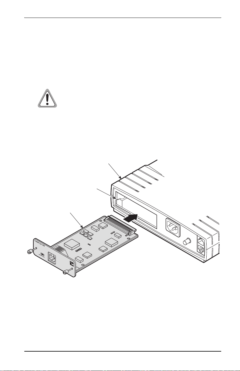
Installing into a Desktop Unit
Install the Campus-REX2 interface card into a Campus-RS or Campus-HRS
desktop unit before you install the desktop unit (install power and HDSL
cables). Install the Campus-RS desktop unit using th e ins tr uctions in the
Campus-RS Desktop Unit User Manual.
Ensure power is off to the desktop unit before you install the
Campus-REX2. Installing the card with the power on may
cause damage to the desktop unit, the card, or to both.
1 Ensure that the desktop unit is not connected to power.
2 Slide the Campus-REX2 into the guide rails in the rear of the
desktop unit.
Campus-RS Desktop Unit chassis
Guide rail
Campus-REX2 RS
Interface card
L
i
n
k
REX2 Router
/
A
c
t
i
v
i
t
y
H
U
B
M
D
I
M
D
I
-
X
P
C
1
0
B
1
a
0
s
0
e
B
-T
a
s
e
-T
x
CAMPUS-RS
120VAC@60Hz
or 220VAC@50Hz
.2A Max
C
O
N
S
O
L
E
L
IN
E
3 Gently press the card into place until it is seated firmly in the mating
connector.
4 Secure the card in place using the two captive screws.
5 Complete the desktop unit installation using the Campus-RS Desktop
Unit User Manual.
Campus-REX2 RS Interface Card User Manual 3
Page 16
Chapter 1 - Installing and Accessing the REX2
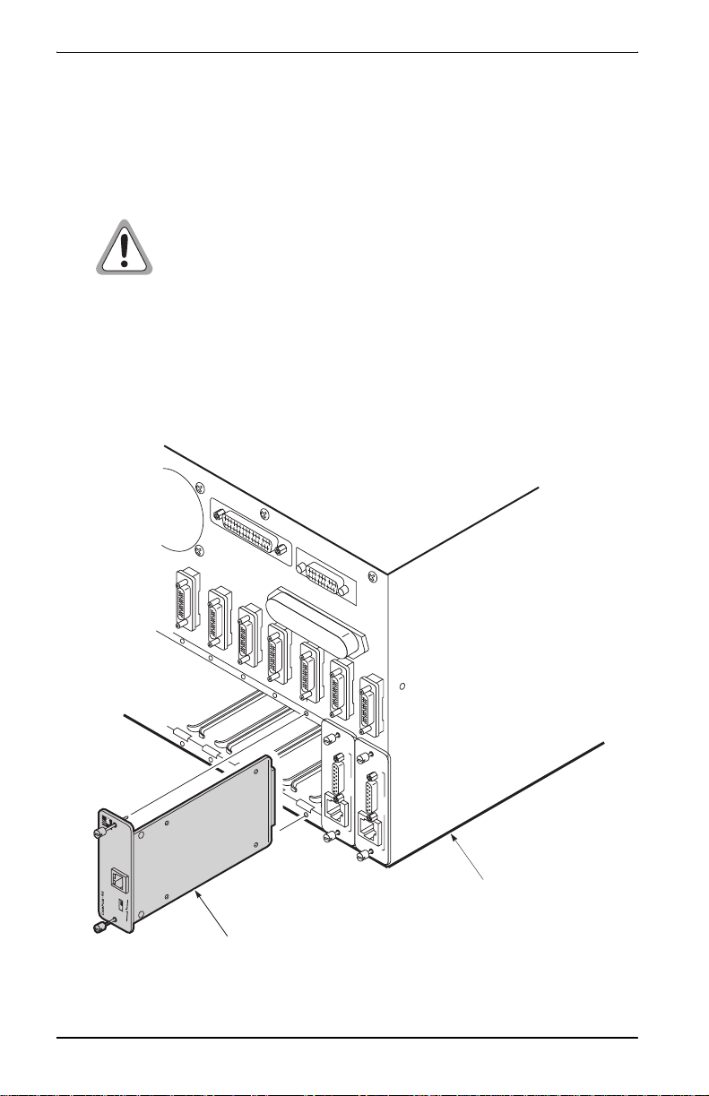
Installing into a Campus-Star Chassis
The Campus-REX2 must be installed into a Campus-Star chassis first, before
you install the corresponding Campus-RS or Campus-HRS line unit.
The Campus-REX2 is not hot-swappable. Damage may occur
to the Campus-REX2, the line unit, or both if the line unit is
installed before you install the Campus-REX2.
1 Ensure that a line unit is not installed in the line-unit slot corresponding
to the slot where you will install the Campus-REX2.
2 Slide the Campus-REX2 into the guide rails of the selected slot at the rear
of the Campus-Star chassis.
DSX-1
DSX-1
-1/T
X
S
620
FG
D
C
Campus-Star
chassis
10 Base-T
REX2 Router
100 Base-Tx
Link/Activity
-1/T
X
S
620
FG
D
C
C
P
I-X
D
M
I
D
M
B
U
H
Campus-REX2 RS Interface card
4 Campu s-REX2 RS Interface Card User Man ual
Page 17

Chapter 1 - Installing and Accessing the REX2
s
3 Gently press the card into place until it is seated firmly in the mating
connector.
4 Secure the card in place using the two captive screws.
5 Install a Campus-RS line unit and connect it to an HDSL line using the
Campus-RS Line Unit User Manual. The line unit provides the DSL
connection for the interface card.
CONNECTING THE ETHERNET LINE
The 10 Base-T and 100 Base-Tx (10/100 Base-T) port on the rear panel of the
Campus-REX2 connects to a LAN through a hub, repeater, or another router.
The port autosenses both the 10/100B ase-T port rate and hal f- or full -duplex
mode of the network device to which it connects and matches the
configuration.
Use a straight-through Catego ry 5 cable to connect the Ethernet por t. Set the
MDI/MDI-X switch to the appropriate position, dependent on the device to
which you are connecting.
1 Set the Campus-REX2 MDI/MDI-X switch to one of the following:
• MDI-X when connecting to
network equipment such as
an Ethernet NIC in a PC or
any other equipment that has
an MDI port
• MDI when connecting to
MDI-X
MDI
Use when connecting
to an MDI port such as
a PC Ethernet NIC
Use when connecting
to an MDI-X port such a
a hub, switch, or router
network equipment such as a
hub, switch, or router or any other equipment that has an
MDI-X port
Campus-REX2 RS Interface Card User Manual 5
Page 18
Chapter 1 - Installing and Accessing the REX2
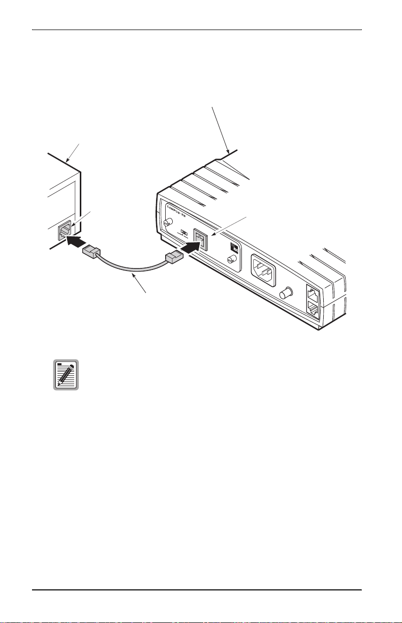
2 Plug one end of the Category 5 cable into the 10/100Base-T connector on
the Campus-REX2 faceplate.
Campus-RS Desktop Unit
PC, hub, router or
other Ethernet equipment
Ethernet port
Link/A
RE
X2 Router
ctivity
H
UB
M
D
I
M
D
I-X
10 B
P
C
ase-T
100 B
ase-Tx
10 Base-T
100 Base-Tx port
120VAC@60Hz
or 220VAC@50Hz
.2A Max
Category 5 cable
The Campus-REX2 10/100Base-T interface operates in either
half- or full-duplex mode which is determined by autosensing
its network connection. Both the LCD menu and console
menu displays the mode.
3 Connect the other end of the Ethernet cable to the local Ethernet
equipment (repeater, PC NIC, or other Ethernet device).
6 Campu s-REX2 RS Interface Card User Man ual
Page 19

Chapter 1 - Installing and Accessing the REX2
POWERING UP AND CHE CKING THE CONNECTION
Verify operating status after completing a full installation that includes
installing of the Campus-REX2 into a desktop unit or Campus-Star chas sis
and then completing the installation of the desktop unit or the Campus-Star
chassis (including the Line Unit):
1 Verify that the power cord is connected to the desktop unit or to the
Campus-Sta r chassis (if yo u have an AC pow er supply) and to an
external power source. Then verify the powerup of and HDSL
connection for that unit as specified in the appropriate user manual.
2 If the Campus-REX2 is installed in a desktop unit, press the power button
to On. The button is located on the back of the desktop unit.
3 Verify that the Link LED on the Campus-REX2 card is green. This
indicates that the 10/100Base-T connection is operating correctly. If the
Link LED does not light green, check the 10/100Base-T cabling
configuration.
If the link LED does not light green, check that the MDI/MDI-X switch
is set to the appropriate position.
Campus-REX2 RS Interface Card User Manual 7
Page 20

Chapter 1 - Installing and Accessing the REX2
SETTING UP ACCESS TO THE CAMPUS UNIT
Configure a Campus system through any of the following:
• a PC connected to the desktop unit Console port
• a PC connected to the Campus-Star line unit Console port
• a telnet session to the Campus-REX2 over the Internet or the CMU in a
Campus-Star chassis
• the LCD menu and buttons on the desktop unit or CMU front panel
• StarGazer or a comparable EMS using SNMP
A Console port or telnet connection provides access to configuration menus
that provide options not available through the LCD menus. Depending on
your immediate configuration requirements, you may not need to set up a PC
immediately. Use the Console port or a telnet session when you:
• configure the Campus-REX2 as a router (only some bri dging and routing
configuration is available using the LCD)
• want to change the HDSL transmission rate and do not want to use the
LCD menus
• will set additional configuration options at this time, such as system or
REX2
• want to view performance statistics for the HDSL and 10/100Base-T
interfaces
If you want to set up a PC at this time, refer to “Setting Up Access to the
Campus Unit” on page 8.
8 Campu s-REX2 RS Interface Card User Man ual
Page 21
Chapter 1 - Installing and Accessing the REX2
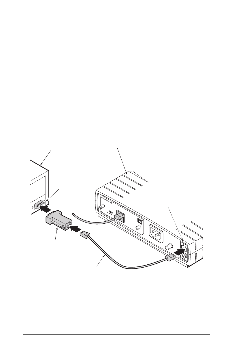
Connecting to the Campus Unit Console Port
Use a terminal or a PC with terminal emulation software (b oth will be referred
to as PC) connected to the Console port to configure Campus system options,
manage the unit, and generate system r eports. The PC connects to the Cons ole
port on the desktop unit, the line unit (in a Campus-Star chassis), or the
CMU-810 installed in the Campus-Star chassis.
1 Connect the Console adapter into the standard 9-pin COM port on the PC
and tighten the attached screws.
2 Plug one end of the console cable into the PC’s COM port or console
adapter, then do one of the following:
• If the Campus-REX2 is installed into a desktop unit, connect the
other end of the console cable into the desktop unit Console port.
PC or terminal
9-pin COM
port
Console adapter
Campus-RS Desktop Unit
Black cable
(Category 3)
ase-Tx
Console port
120VAC@60Hz
or 220VAC@50Hz
.2A Max
Lin
R
k/A
EX
ctivity
2 R
outer
H
U
B
M
D
I
M
D
I-X
10 Base-T
P
C
100 B
Campus-REX2 RS Interface Card User Manual 9
Page 22
Chapter 1 - Installing and Accessing the REX2
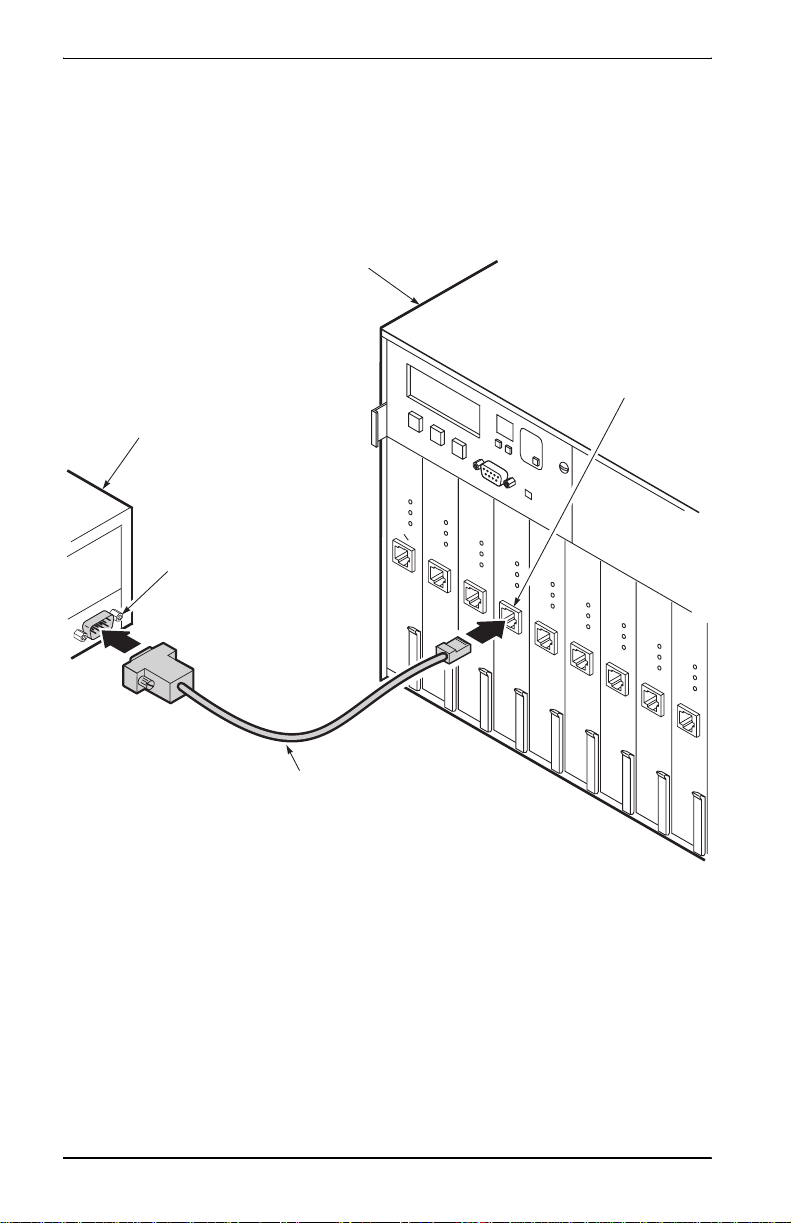
• If the Campus-REX2 is installed in a Campus-Star chassis, do one
of the following:
– plug the oth er end of the console cable into the Co nsole port on
the front of the line unit
Campus-Star chassis
C
M
U
-7
1
0
M
A
N
A
G
E
M
PC or terminal
9-pin COM
port
P
O
W
C
am
LIN
HDSL
TEST
PORT
RS-232
CONSOLE
E
N
T
U
N
C
am
L
IN
HDSL
TEST
PORT
RS-232
CONSOLE
IT
S
L
O
T
A
L
A
R
M
S
M
AJOR
MINOR
ACO
pus HR
E U
S
N
IT
Cam
LINE UN
HDSL
TEST
PORT
RS-232
CONSOLE
R
E
S
E
pu
T
s H
RS
IT
C
amp
us HR
L
IN
E U
S
NIT
Cam
pus H
L
IN
E UN
HDSL
TEST
HDSL
PORT
TEST
PORT
RS-232
CONSOLE
RS-232
CONSOLE
E
R
pus HR
E UN
S
IT
RS
IT
Ca
LIN
HDSL
TEST
PORT
CONSOLE
m
pus H
R
E UNI
S
T
C
HDSL
TEST
PORT
RS-232
CONSOLE
Console port
am
pus HR
L
INE UN
S
IT
C
am
pus HR
L
IN
E UN
S
IT
Cam
LINE
HDSL
TEST
HDSL
PORT
TEST
RS-232
CONSOLE
PORT
RS-232
CONSOLE
RS-232
pu
s H
RS
U
NIT
Category 3 Cable
10 Campus-REX2 RS Interface Card User Manual
Page 23
Chapter 1 - Installing and Accessing the REX2
3
O
r
– plu g the othe r end of the cons ole cable int o the Consol e port of
the CMU-810 Management unit (when installed ), as des cribed
in the Campus-Star with CMU-810 User Manual
Campus-Star chassis
PC or terminal
CMU-810
9-pin COM
port
Adapter
Cable
A
L
A
R
M
S
M
A
J
O
R
MANAGEMENT UNIT
M
I
N
O
R
AC
O
N
E
C
X
am
T
pu
L
s H
INE UN
HDSL
TEST
PORT
RS-232
CONSOLE
P
a
ir
E
RS
N
T
E
IT
R
C
am
E
P
pu
L
IN
HDSL
TEST
PORT
RS-232
CONSOLE
P
a
S
s H
RS
E
U
NIT
C
am
pu
LIN
s HR
E U
S
N
IT
C
am
pus HR
LIN
E UN
HDSL
TEST
HDSL
PORT
TEST
PORT
RS-232
CONSOLE
RS-232
CONSOLE
ir
P
a
ir
P
a
ir
SLOT
S
IT
Cam
PORT
Pair
CMU-810
Console port
PairGain
RS-232
pu
L
s H
INE UN
RS
IT
Cam
LIN
HDSL
TEST
HDSL
TEST
PORT
RS-232
CONSOLE
RS-232
CONSOLE
P
a
pu
s H
RS
E
U
NIT
C
am
pu
LIN
s H
R
E
U
S
NIT
HDSL
TEST
PORT
RS-232
CONSOLE
ir
P
a
ir
P
3 Configure the terminal or PC terminal emulation software with the
following communications settings:
Cam
PORT
LIN
HDSL
TEST
RS-232
CONSOLE
a
pu
s H
RS
E
U
NIT
C
ampu
L
s
IN
E U
HDSL
TEST
PORT
RS-2
CONS
ir
P
a
i
• 9600 baud
• no parity
• 8 data bits
• 1 stop bit
• no hardware flow control
Campus-REX2 RS Inter face Card User Manual 11
Page 24
Chapter 1 - Installing and Accessing the REX2
LOGGING IN
Access the Campus-REX2 menus for configuration and management using
any of these four logins, which can be concurrently connected:
• a telnet session to the Campus-REX2 (see below)
• a login to the local Campus unit through the Cons ole port (see “Logging
In a Local Campus Unit through the Console Port” on page 13)
• a logon from a remote Campus unit through its Main Menu (see
“Logging On a Remote Campus Unit” on page 15)
• a login through the CMU in the Campus-Star chassis
Logging In a Campus Unit Using Telnet
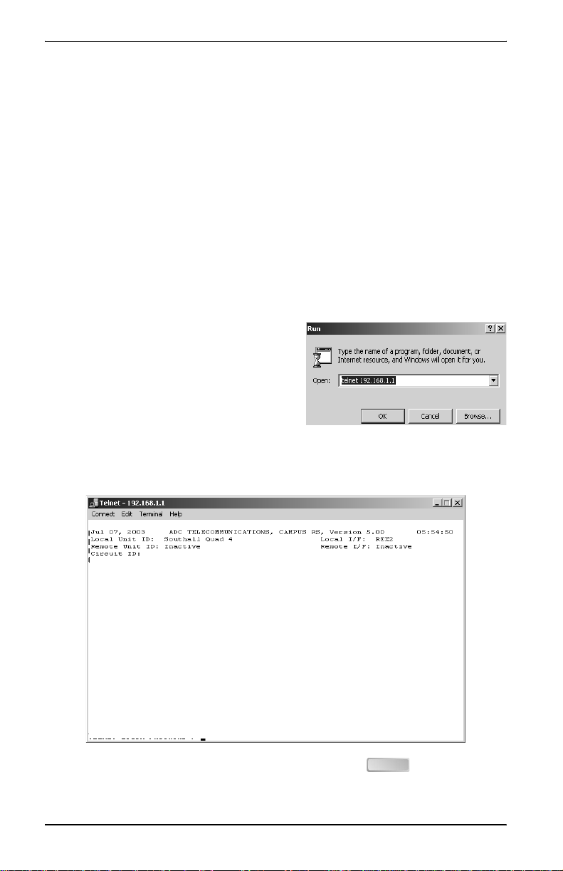
Use telnet protocol to access the
Campus unit for configuration and
management over the Internet. From the
Windows Start menu, select Run. Enter
the telnet command and the IP address
for the Campus-REX2 (default IP
address is 192.168.1.1). The timeo ut for
disconnecting a telnet session is five minutes (time frame with no keyboard
activity to the Campus unit). The following login screen is displayed:
TELNET LOGIN PASSWORD >
Enter the configured password (default password is ) to log on the
ENTER
Campus-REX2 Main Menu.
12 Campus-REX2 RS Interface Card User Manual
Page 25

Chapter 1 - Installing and Accessing the REX2
Logging In a Local Campus Unit through the Console Port
You previously set up the terminal communication settings (Ste p 3 on page
1-11) for your PC to access the Campus unit. From your terminal emulation
software or your terminal, do the following:
1 Press the on the PC keyboard several times until the baud rate
SPACEBAR
is establish ed and the Login Password screen is displayed as shown
below.
Jul 07, 2003 ADC TELECOMMUNICATIONS, CAMPUS RS, Version 5.1 08:19:34
Local Unit ID: Local I/F: REX2
Remote Unit ID: Inactive Remote I/F: Inactive
Circuit ID:
LOGIN PASSWORD >
If the system does not respond when you attempt to log on, ensure that
hardware flow control is turned off in the terminal emulation software on
the PC or for the terminal.
Campus-REX2 RS Inter face Card User Manual 13
Page 26

Chapter 1 - Installing and Accessing the REX2
2 Press (default pas sword) to log on. If a password was p reviously
ENTER
configured, type that password then press . The Main Menu is
ENTER
displayed.
Jul 07, 2003 ADC TELECOMMUNICATIONS, CAMPUS RS, Version 5.1 08:19:34
Local Unit ID: Local I/F: REX2
Remote Unit ID: Inactive Remote I/F: Inactive
Circuit ID:
MAIN MENU
1) SYSTEM STATUS
2) REX2 CONFIGURATION AND STATUS
3) SYSTEM CONFIGURATION
4) MAINTENANCE
5) REMOTE LOGON
ENTER CHOICE>
(L)ogout
Once you are logged into the Campus unit through the console port, there is
no timeout defined for the session. You will stay connected until you either
log out or the Campus unit dete cts a disconnected console cable (DTR signal
changes to inactive).
14 Campus-REX2 RS Interface Card User Manual
Page 27

Chapter 1 - Installing and Accessing the REX2
Logging On a Remote Campus Unit
Log on the remote Campus unit which is at the far end of the HDSL
connection from the local Campus unit you are logged into. The remote
Campus unit is accessed through the Main Menu of the local Campus unit:
1 From the Main Menu of the local Campus-REX2, type then press
. The following message is displayed:
ENTER
5
Enter <ESC><ESC> to Exit Remote Login Mode.
Remote Login, Please wait......
You can exit from this function or from the remote login by pressing
twice. The following logon screen is displayed.
ESC
Jul 07, 2003 ADC TELECOMMUNICATIONS, CAMPUS RS, Version 5.1 08:19:34
Local Unit ID: Southall Quad 4 Local I/F: REX2
Remote Unit ID: Central Remote I/F: REX2
Circuit ID: Southeast line 421
REMOTE_LOGON PASSWORD >
The menu header changes to indicate the remote unit ID as the local unit,
and local unit ID as the remote. This shows that the terminal program is
physically connected to the local unit, but is configuring as if it were
connected to the remote unit.
If the remote unit is also a Campus-REX2, the screens and procedures on
the Remote Main Menu are identical to those on the Local Main Menu,
except the REMOTE LOGON option is not available. If the remote unit
is not a Campus-REX2, the screens support that remote interface card
(see the appropriate interface card user manual for a description of the
screens and configuration options).
Campus-REX2 RS Inter face Card User Manual 15
Page 28
Chapter 1 - Installing and Accessing the REX2
LOGGING OFF
From the Main Menu, type then press to logout of the unit menus.
If the Main Menu is not the current menu, type o r (when available) then
press to return to the Main Menu where you can logout as described
ENTER
L ENTER
R M
above. The logout procedure is the same whether you are connected to the
console port or through a telnet session.
USING THE MENUS
The bottom of each menu screen identifies all of the keys you can use on that
screen. Several keys operate identically on all of the menu screens:
To: Do this:
Access menu items Type the number of the item then press .
Return to the previous menu Type then press .
Return to the Main Menu Type then press when the menu is more
Clear or update status
information
R ENTER
M ENTER
than one level below the Main Menu.
• Type
• Type
then press to clear or reset the
C ENTER
information on a status screen.
then press to update the
U ENTER
information on a status screen.
ENTER
Configure options as describe d bel ow:
For this option type: Do this:
Select a value from a list of
predefined values
Type in required information 1 Type the number of the option then press .
16 Campus-REX2 RS Interface Card User Manual
1 Type the number of the option then press .
The option setting changes to the next value in the
list and the screen redraws.
2 Repeat the first step until the option is set to the
preferred value.
The screen prompts you for information.
2 Type the information in the format requested then
ENTER
press .
ENTER
ENTER
Page 29

Chapter 1 - Installing and Accessing the REX2
When you have selected or entered configuration changes for some
parameters such as bridging or routing, you m ust save those changes for them
to be permanent (saved if power to the Campus-REX2 is cycled). Type
R
from a configuration screen until you return to the root for that configuration
and then save the changes. For example, the REX2 Conf iguration and Status
screen is the root for REX2 configuration.
OPERATING WITH DEFAULT VALUES
Campus-REX2 can be operated using its default settings which include:
• HDSL Operat i ng Mode set to St andard Mode
• Standard Mode HDSL Rate set to T1
• network protocol set to bridge, with the encapsulation format set to
cHDLC
• Spanning Tree protocol disabled
• Timing Source set to Internal
Set other configurable options to customize the Campus system to your
network requirement as described in the following chapters. The LAN port
has a default IP address assigned (192.168.1.1) that you can change to fit your
IP networki ng scheme.
Campus-REX2 RS Inter face Card User Manual 17
Page 30

Chapter 1 - Installing and Accessing the REX2
18 Campus-REX2 RS Interface Card User Manual
Page 31

CONFIGURING
HDSL PARAMETERS
Campus units have a default HDSL configuration to operate in Standard
Mode with a T1 (1.544 Mbps) HDSL Rate. This default configuration is
compatible with othe r Campus-RS and Campus -HRS products (in cluding the
Campus-T1 desktop units and line units) if you choose to operate them in
their default configuration.
For: See Page:
Configuring HDSL Parameters 20
Configuring HDSL Alarms 26
You can also configure the HDSL parameters through the LCD menus.
See “Using the LCD for Configuration and Management” on page 7-97
for instructions on using the LCD panel. To view system performance and
other status information, see “Monitoring and Testing the Campus System”
on page 5-73.
Changes to the HDSL operating mode or transmission rate are
not automatically made to the remote unit. These changes
must be made at both the local and remote units for the HDSL
link to be re-established. If the remote unit is not easily
accessible, you can follow the instruct ions in “Logging On a
Remote Campus Unit” on page 1-15 to use a PC for a remote
logon (if an HDSL link is up) and make the preferred change.
When you change the HDSL settings on the remote unit, the
HDSL link is lost; it is re-established when you make the
identical change(s) on the local unit.
2
Campus-REX2 RS Inter face Card User Manual 19
Page 32

Chapter 2 - Configuring HDSL Parameters
CONFIGURING HDSL PARAMETERS
Access the HDSL configuration screen, then configure parameters.
Accessing HDSL Configuration
From the Main Menu (page 14), type then press to access the
3
ENTER
System Settings Menu.
Jul 07, 2003 ADC TELECOMMUNICATIONS, CAMPUS RS, Version 5.1 08:19:34
Local Unit ID: Local I/F: REX2
Remote Unit ID: Inactive Remote I/F: Inactive
Circuit ID:
SYSTEM SETTINGS MENU
1) SYSTEM PARAMETERS
2) HDSL PARAMETERS
ENTER CHOICE>
From the System Settings Menu, type then press to access the
(R)eturn
2 ENTER
HDSL Parameters screen. From this screen, you can configure or change
values. Standard Mode is the default HDSL Parameters screen.
Jul 07, 2003 ADC TELECOMMUNICATIONS, CAMPUS RS, Version 5.1 08:19:34
Local Unit ID: Local I/F: REX2
Remote Unit ID: Inactive Remote I/F: Inactive
Circuit ID:
STANDARD MODE HDSL PARAMETERS
1) HDSL Operating Mode: Standard (Standard, Extended)
2) Transceiver Mode: Auto (Auto, Master, Slave)
3) HDSL Rate: T1 (T1, E1, 768)
Enter (S)ave to apply changes !
ENTER CHOICE>
(S)ave (R)eturn (M)ain Menu
20 Campus-REX2 RS Interface Card User Manual
Page 33

Chapter 2 - Configuring HDSL Parameters
Selecting HDSL Parameters
You can use the default HDSL setting for your Campus-RS unit (when also
using the default settings on the remote unit to which this unit connects)
which are:
• standard for the HDSL operating mode
• auto for the transceiver mode (determines which device is the master
or slave)
• T1 for the HDSL rate
If you want to change any of these parameters, select one of the following
sections based on the HDSL operating mode you will use. Campus-RS offers
these two HDSL operating modes:
• Standard mode (page 22) provides compatibility between a Campus-RS
product and an earlier Campus product (legacy Campus) that has a
HDSL interface including T1, E1, or 768:
– for T1, the maximum transmission rate is 1.544 Mbps over 2 pairs
– for E1, the maximum transmission rate is 2.048 Mbps over 2 pairs
– for 768, the transmission rate is 768 kbps over 1 pair
• Extended mode (page 23) pr ovides a fractional rate se lection between the
HDSL interfaces of two Campus-RS products. The rate is selectable as
follows:
– for 1 pair in 64 kbps increments, starting at 128 kbps up to
2.304 Mbps
– for 2 pair in 128 kbps increments, starting at 256 kbps up to
4.608 Mbps
Campus-REX2 RS Inter face Card User Manual 21
Page 34

Chapter 2 - Configuring HDSL Parameters
Using Standard Mode
Standard mode is the default configuration for the HDSL operating mode.
When standard mode is selected, only three HDSL rates (T1, E1, and 768) are
available. You can select any of the three options for transceiver mode,
however.
1 From the HDSL Parameters menu, type then press if the
1 ENTER
HDSL Operating Mode is set t o Exten ded. S tandard is now di splayed as
the HDSL Operating Mode.
It is recommended that you leave the Transceiver Mode
option set to Auto unless you re quire that a particular end of
the HDSL connection be the Master or Slave.
Also, this value cannot be changed if the HDSL link is up.
2 To change the Transceiver Mode, type then press . The
2 ENTER
Transceiver Mode changes to the next setting. Repeat until the preferred
setting is selected:
• Master initiates the HDSL link. The other Campus unit must be set
to Slave or Auto.
• Slave waits for the other Campus unit to initiate the HDSL link. The
other unit must be set to Master or Auto.
• Auto (default) automatically switches between Master and Slave
until an HDSL link is established.
The Transceiver Mode option determines the hierarchy of the two
Campus units when attempting to establish an HDSL link.
3 To change the HDSL Rate, type then press . The HDSL Rate
3 ENTER
changes to the next setting. Repeat until the HDSL Rate is set to the
preferred setting of T1 (default), E1, or 768.
4 Type to save and apply HDSL changes as prompted by:
S
Enter (S)ave to apply changes !
5 To exit the menu, type (go back one screen) or (return to the Main
R M
Menu).
22 Campus-REX2 RS Interface Card User Manual
Page 35

Chapter 2 - Configuring HDSL Parameters
Using Extended Mode
With Extended mode, the HDSL link can comprise either one or two loops
with a rate selection in 64 (1 pair) or 128 (2 pair) kbps increments. The
transmission rate between t wo Campus-RS products is up to 4.608 Mbps with
two pair or 2.304 Mbps with one pair. Both the one loop network or two loop
network operate only in full-duplex transmission.
1 From the HDSL Parameters menu, type th en press . The
1 ENTER
HDSL Operating Mode options changes from Standard to Extended as
shown below .
Jul 07, 2003 ADC TELECOMMUNICATIONS, CAMPUS RS, Version 5.1 08:19:34
Local Unit ID: Local I/F: REX2
Remote Unit ID: Inactive Remote I/F: Inactive
Circuit ID:
EXTENDED MODE HDSL PARAMETERS
1) HDSL Operating Mode: Extended (Standard, Extended)
2) Transceiver Mode: Auto (Auto, Master, Slave)
3) HDSL Loop Mode: 2 Loops (1 Loop, 2 Loops)*
4) HDSL Rate: 256
*Note:
1 Loop = single loop, full duplex
2 Loops = two loops, full duplex
Enter (S)ave to apply changes !
ENTER CHOICE>
(S)ave (R)eturn (M)ain Menu
Campus-REX2 RS Inter face Card User Manual 23
Page 36

Chapter 2 - Configuring HDSL Parameters
It is recommended that you leave the Transceiver Mode
option set to Auto unless you require that particular ends of
the HDSL connection be the Master and Slave.
Also, this value cannot be changed if the HDSL link is up.
2 To change the Transceiver Mode, type then press . The
2 ENTER
Transceiver Mode changes to the next setting. Repeat until the preferred
setting is selected:
• Master initiates the HDSL link. The other Campus unit must be set
to Slave or Auto.
• Slave waits for the other Campus unit to initiate the HDSL link. The
other unit must be set to Master or Auto.
• Auto (default) automatically switches between Master and Slave
until an HDSL link is established.
The Transceiver Mode option determines the hierarchy of the two
Campus units when attempting to establish an HDSL link.
3 To change the HDSL Loop Mode from 1 Loop (defaul t) to 2 Loop, t ype
then press .
3 ENTER
4 To select an HDSL Rate, type then press . The Select HDSL
4 ENTER
Rate screen that is displayed is dependent on whether you selected
1 Loop or 2 Loop for the HDSL Loop Mode. The minimum and
maximum rates are:
• for 1 Loop, 128 kbps is the minimum and 2304 Mbps is the
maximum selected in 64 kbps increments; the default is 128 kbps
• for 2 Loop, 256 kbps is the minimum and 4608 Mbps is the
maximum selected in 128 kbps increments; the default is 256 kbps
24 Campus-REX2 RS Interface Card User Manual
Page 37

Chapter 2 - Configuring HDSL Parameters
Choose a rate from one of the following:
• For 1 Loop, the Select HDSL Low Rate screen is displayed. To
select a rate, type a number from 2 to 36 then press .
Jul 07, 2003 ADC TELECOMMUNICATIONS, CAMPUS RS, Version 5.1 08:19:34
Local Unit ID: Local I/F: REX2
Remote Unit ID: Inactive Remote I/F: Inactive
Circuit ID:
SELECT HDSL LOW RATE
Current HDSL Rate: 128
Current Loop Mode: 1 Loop
1) N/A 13) 832 kbps 25) 1600 kbps
2) 128 kbps 14) 896 kbps 26) 1664 kbps
3) 192 kbps 15) 960 kbps 27) 1728 kbps
4) 256 kbps 16) 1024 kbps 28) 1792 kbps
5) 320 kbps 17) 1088 kbps 29) 1856 kbps
6) 384 kbps 18) 1152 kbps 30) 1920 kbps
7) 448 kbps 19) 1216 kbps 31) 1984 kbps
8) 512 kbps 20) 1280 kbps 32) 2048 kbps
9) 576 kbps 21) 1344 kbps 33) 2112 kbps
10) 640 kbps 22) 1408 kbps 34) 2176 kbps
11) 704 kbps 23) 1472 kbps 35) 2240 kbps
12) 768 kbps 24) 1536 kbps 36) 2304 kbps
ENTER CHOICE>
(R)eturn (M)ain Menu
ENTER
• For 2 Loop, the Select HDSL High Rate screen is displayed. To
select a rate, type a number from 2 to 36 then press .
ENTER
Jul 07, 2003 ADC TELECOMMUNICATIONS, CAMPUS RS, Version 5.1 08:19:34
Local Unit ID: Local I/F: REX2
Remote Unit ID: Inactive Remote I/F: Inactive
Circuit ID:
SELECT HDSL HIGH RATE
Current HDSL Rate: 256
Current Loop Mode: 2 Loops
1) N/A 13) 1664 kbps 25) 3200 kbps
2) 256 kbps 14) 1792 kbps 26) 3328 kbps
3) 384 kbps 15) 1920 kbps 27) 3456 kbps
4) 512 kbps 16) 2048 kbps 28) 3584 kbps
5) 640 kbps 17) 2176 kbps 29) 3712 kbps
6) 768 kbps 18) 2304 kbps 30) 3840 kbps
7) 896 kbps 19) 2432 kbps 31) 3968 kbps
8) 1024 kbps 20) 2560 kbps 32) 4096 kbps
9) 1152 kbps 21) 2688 kbps 33) 4224 kbps
10) 1280 kbps 22) 2816 kbps 34) 4352 kbps
11) 1408 kbps 23) 2944 kbps 35) 4480 kbps
12) 1536 kbps 24) 3072 kbps 36) 4608 kbps
ENTER CHOICE>
5 Type to exit the menu. (Typing will return you to the Main Menu.)
6 Type to save and apply HDSL changes as prompted by:
R M
S
(R)eturn (M)ain Menu
Enter (S)ave to apply changes !
Campus-REX2 RS Inter face Card User Manual 25
Page 38

Chapter 2 - Configuring HDSL Parameters
CONFIGURING HDSL ALARMS
You can configure options for four types of alarms:
• HDSL ES Alarm Threshold determines the number of errored seconds
that must occur to trigger an alarm.
• HDSL Margin Alarm Threshold determines the margin, in dB, that
triggers an alarm.
• Alarm on Local I/F LOS lets you enable or disable the local Loss of
Signal alarm.
• Alarm on Remote I/F LOS lets you enable or disable the remote Loss of
Signal alarm.
Access the configuration screen, then set the options.
Accessing HDSL Alarms Configuration
1 From the Main Menu (page 14), type then press to access the
3 ENTER
System Settings Menu.
Jul 07, 2003 ADC TELECOMMUNICATIONS, CAMPUS RS, Version 5.1 08:19:34
Local Unit ID: Local I/F: REX2
Remote Unit ID: Remote I/F: REX2
Circuit ID:
SYSTEM SETTINGS MENU
1) SYSTEM PARAMETERS
2) HDSL PARAMETERS
ENTER CHOICE>
(R)eturn
26 Campus-REX2 RS Interface Card User Manual
Page 39

Chapter 2 - Configuring HDSL Parameters
2 From the System Settings Menu, type then press . The System
1 ENTER
Parameters screen is displayed.
Jul 07, 2003 ADC TELECOMMUNICATIONS, CAMPUS RS, Version 5.1 08:19:34
Local Unit ID: Local I/F: REX2
Remote Unit ID: Remote I/F: REX2
Circuit ID:
SYSTEM PARAMETERS
1) CHANGE SYSTEM TIME
2) CHANGE SYSTEM DATE
3) CHANGE UNIT ID
4) CHANGE CIRCUIT ID
5) CHANGE UNIT PASSWORD
6) HDSL ES Alarm Threshold: Disabled (Disabled, 17, 170)
7) HDSL Margin Alarm Threshold: Disabled
8) Local Data Port LOS Alarm: Disabled (Disabled, Enabled)
9) Remote Data Port LOS Alarm: Disabled (Disabled, Enabled)
10) RESTORE FACTORY DEFAULTS
ENTER CHOICE>
(R)eturn (M)ain Menu
Setting HDSL Alarms
The default setting for all alarming is Disabled. Completing the following
steps to either select a value or to enable the alarm reporting.
1 To select an HDSL ES Alarm Threshold (Disabled is the default), type
then press to select one of the following as the ES threshold:
6 ENTER
• 17 errored seconds occurring in a 24-hour period
• 170 errored seconds occurring in a 24-hour period
An alarm is generated when the defined threshold for HDSL errored
seconds is exceeded, indicating a deterioration in performance. An
errored second is one in which one or more block errors (CRC
anomalies) or LOSW defects occur within the threshold interval.
2 To configure the HDSL Margin Alarm Threshold:
a Type then press .
7 ENTER
b At the prompt, enter a value between 1 and 25 decibels (dB) then
press .
ENTER
Enter Margin alarm threshold value (1-25dB), or "D"
to disable>6
An alarm is generated when the defined threshold for HDSL Margin is
exceeded. Margin indicates the signal to noise ratio at a receiver point.
Campus-REX2 RS Inter face Card User Manual 27
Page 40

Chapter 2 - Configuring HDSL Parameters
3 To enable the Local Data Port LOS Alarm, type then press .
8 ENTER
When enabled, an alarm is generated when a loss of signal is detected at
the data port on the local Campus unit. (To disable this alarm, repeat the
procedure).
4 To enable the Remote Data LOS Alarm, type then press .
9 ENTER
When enabled, an alarm is generated when a loss of signal is detected at
the data port on the local Campus unit. (To disable this alarm, repeat the
procedure).
The new HDSL alarm settings take effect immediately after entered and a
save command is not required.
28 Campus-REX2 RS Interface Card User Manual
Page 41

CONFIGURING THE REX2
The Campus-REX2 RS is a 10/100Base-T Ethernet interface card that
provides connectivity for LAN services. The Campus-REX2, as its default
configuration, provides IEEE 802.1d transparent MAC level bridging.
You can change the default configuration to routing and set the appropriate
IP parameters for the LINE and LAN. Also, you can set up parameters for
SNMP management.
You can use the Campus-REX2 with its default settings that include bridge
mode, cHDLC encapsulation, and Spanning Tree protocol set t o dis abled. If,
however, you require to change any of these parameters for implementing
your network, use the procedures in this chapter.
For: See Page:
Accessing the REX2 Configuration and Status Screen 30
Configuring the Campus-REX2 as a Bridge 30
Configuring the Campus-REX2 as a Router 44
Configuring the Campus-REX2 for SNMP Management 60
You can also configure SNMP parameters which provide a way to manage
the Campus-REX2 system over a network.
3
Some of the bridging parameters can also be configured through the LCD
menus. See “Using the LCD for Conf iguration and Management” on page 97
for instruction. For an overview of bridges, routers, and other network
management concepts, see “Internetworking an d Management Overview” on
page 119.
The Campus-REX2 supports forwarding larger-sized VLAN f rames. There is
no configuration required to pass VLAN traffic with frame sizes between 64
and 1536 bytes.
Campus-REX2 RS Inter face Card User Manual 29
Page 42

Chapter 3 - Configuring the REX2
ACCESSING THE REX2 CONFIGURATION AND
TATUS SCREEN
S
From the Main Menu (page 1-14), type then press to access the
2 ENTER
REX2 Configuration and Status screen.
Jul 07, 2003 ADC TELECOMMUNICATIONS, CAMPUS RS, Version 5.1 08:19:34
Local Unit ID: Local I/F: REX2
Remote Unit ID: Remote I/F: REX2
Circuit ID:
REX2 CONFIGURATION AND STATUS
LAN STATUS: 100BaseT, Full Duplex, Up
LINE STATUS: Standard, Auto, T1, Up
MAC ADDRESS: 00:20:A7:01:02:08
1) Network Protocol: Bridge (Bridge, Router)
2) Encapsulation: cHDLC (cHDLC, PPP)
3) Timing Source: Internal (Internal, HDSL)
4) BRIDGE CONFIGURATION
5) BRIDGE STATISTICS
6) SNMP CONFIGURATION
ENTER CHOICE>
(R)eturn
CONFIGURING THE CAMPUS-REX2 AS A BRIDGE
A bridge moves information across a network fro m a sou rce to a desti nation
at the link layer (of an OSI reference model). The information is sent to a
physical address known as a Media Access Control (MAC) address. See
“MAC-Level Bridging and Spanning Tree Protocol” on page 124 for more
information about bridging.
This section describes how to configure the bridge (default setting) options
found on the screen shown above for the Campus-REX2, including:
• “Configuring Bridge Protocol, Encapsulation and Timing” on page 31
• “Configuring Bridge Features” on page 32
– “Configuring Spanning Tree Protocol” on page 33
– “Configuring the Bridge Unit IP” on page 38
• “Saving the Bridge Configuration” on page 40
• “Accessing the Bridge and ARP Tables” on page 41
30 Campus-REX2 RS Interface Card User Manual
Page 43

Chapter 3 - Configuring the REX2
Configuring Bridge Protocol, Encapsulation and Timing
The Campus-REX2, as a default configuration, bridges Ethernet frames.
1 Type then press if bridge is not selected.
2 To change the packet encapsulation, type then press . Select an
1 ENTER
2 ENTER
Encapsulation option:
• cHDLC for Campus-REX2 to another Campus-REX2 application
• PPP when the remote Campus unit has a synchronous interface card
such as a V.35 or when connecting to Ethernet equipment from
another manufacturer
3 To change the timing source, type then press . Select a timing
3 ENTER
source setting:
• Internal (default setting) which takes its timing from an internal
oscillator
• HDSL which takes its timing from the HDSL link
The Timing Source option determines the sour ce of circuit timing on the
HDSL link. The proper setting of the Timing Source option depends
upon the interface card of the remote Campus unit:
• If the Campus-REX2 is connected to a Campus unit with another
Campus-REX2, leave the Timing Source option set to Internal. Set
the other end (remote) of the connection to HDSL; the Campus
system will not operate properly if both units are set to HDSL.
• If the Campus-REX2 is connected to a Campus unit with a
synchronous interface card, such as a Fractional V.35 card, the
timing source depends on the setting of the Primary Timing Source
option of the remote unit:
– Set the Timing So urce to HDSL if the rem ote unit is set to
Internal or Data Port.
– Set the Timing So urce to Internal if the remote unit is set to
HDSL.
See the Campus-RS Fractional Interface Card User Manual for
information on the Primary Timing Source option.
• If the Campus-REX2 is connec ted to a Cam pus unit wi th a Campu s
CSU/DS-1 or CSU/DSX-1 interface card, set the Timing Source
option to Internal.
Campus-REX2 RS Inter face Card User Manual 31
Page 44

Chapter 3 - Configuring the REX2
Configuring Bridge Features
This section provides procedures for configuring bridging features such as
filter aging and Spanning Tree Protocol. And, although a bridge does not
require an IP address, you will set up IP co nfiguration for the un it so that you
can access it for management using SNMP, telnet, or FTP.
1 To configure the bridge, from the REX2 Configuration and Status screen
type then press . The Bridge Configuration screen is displayed.
4 ENTER
Jul 07, 2003 ADC TELECOMMUNICATIONS, CAMPUS RS, Version 5.1 08:19:34
Local Unit ID: Local I/F: REX2
Remote Unit ID: Remote I/F: REX2
Circuit ID:
BRIDGE CONFIGURATION
1) Bridge Filter Age (sec): 300 (10 - 100000)
2) SPANNING TREE CONFIGURATION
3) BRIDGE TABLE
4) ARP TABLE
UNIT IP 5) IP Configuration: Static (Static, DHCP Client)
6) IP Address: 192.168. 1. 1
Subnet Mask: 255.255.255. 0
7) Default Gateway: 0 .0 .0 .0
ENTER CHOICE>
(R)eturn (M)ain Menu
The bridge and Address Resolution Protocol (ARP) tables are
dynamically built and can be accessed from this screen. See “Viewing
the Bridge Table” on page 41 and “Viewing the ARP Table” on page 42
for more information.
2 To set the bridge filter age, type then press . Enter the filter age
1 ENTER
time in seconds from 10 to 100000 (300 is the default) at the prompt:
Enter New Bridge Filter Age in Seconds : 1000
The bridge filter age indicates the time in seconds in which a MAC
address entry is eliminated from the bridging table if it is not relearned.
3 If you want to enable Sp anning Tree P rotocol , contin ue to “Configuring
Spanning Tree Protocol” on page 33.
32 Campus-REX2 RS Interface Card User Manual
Page 45

Chapter 3 - Configuring the REX2
Configuring Spanning Tree Protocol
Complete this section if you want to enable Spanning Tree Protocol (STP).
Spanning Tree Protocol is disabled as a default configuration. See “About
Spanning Tree Protocol” on page 124 for more information about the
protocol.
1 From the Bridge Configuration screen (page 3-32), type then press
. The Spanning Tree Configuration screen is displayed.
ENTER
2 To enable Spanning Tree Protocol, type then press . (You can
1 ENTER
2
also change the Spanning Tree option to Disabled when Enabled is
selected by typing .)
Jul 07, 2003 ADC TELECOMMUNICATIONS, CAMPUS RS, Version 5.1 08:19:34
Local Unit ID: Local I/F: REX2
Remote Unit ID: Remote I/F: REX2
Circuit ID:
UNIT 1) Spanning Tree Protocol: Enabled (Disabled, Enabled)
2) Bridge Priority: 32768 (0 - 65535)
3) Max Age (sec): 20 (6 - 40)
4) Hello Time (sec): 2 (1 - 10)
5) Forward Delay (sec): 15 (2 - 30)
PORTS 6) LAN Port Priority: 128 (0 - 255)
7) LAN Port Cost: 100 (0 - 65535)
8) Line Port Priority: 128 (0 - 255)
9) Line Port Cost: 648 (0 - 65535)
10) SPANNING TREE STATUS
ENTER CHOICE>
1
SPANNING TREE CONFIGURATION
(R)eturn (M)ain Menu
Item 10 which allows you to view Spanning Tree Status is available on ly
when Spanning Tree Protocol is enabled.
3 To set the Bridge Priority, type then press . At the prompt,
2
ENTER
enter a value for the bridge priority between 0 and 65535 (default value
is 32768):
Enter New Bridge Priority : 24000
The bridge priority is set relative to other bridges in the same bridged
LAN. The spanning tree priority indicates how centrally located this
bridge is in its network. A lower number indicates a more centrally
located bridge.
Campus-REX2 RS Inter face Card User Manual 33
Page 46

Chapter 3 - Configuring the REX2
4 Set the maximum age, the hello time, and the forward delay using the
following procedures. These values are related. If you choose incorrect
values, an error message displays
Value entered is not within constraints
2 * (Forward Delay - 1) >= Max Age > 2 * (Hello
Time + 1)
:
a To set the maximum age, type then press . At the prompt,
3
ENTER
enter a value in seconds. This value indicates the maximum age fo r
Spanning Tree information in the bridging table before it is
discarded. The valid range is 6 to 40 seconds (default value is 20
seconds):
Enter New Max Age : 30
b To set the hello time, type then press . At the prompt,
4 ENTER
enter a time interval in seconds at which the Campus-REX2 should
send Spanning Tree Protocol p ackets (BPDUs). The valid range i s 1
to 10 seconds (the default value is 2 seconds):
Enter New Hello Time : 4
c To set the forward dela y, type then press . At the prompt,
5 ENTER
enter a time interval in seconds that should be waited until the state
of an interface can change. The valid range is 2 to 30 seconds (the
default value is 15 seconds):
Enter New Forward Delay : 30
This delay prevents interface states from changing so rapidly that
Spanning Tree Protocol cannot keep up with the current network
topology and therefore cannot efficiently manage bridging.
5 To set the LAN port priority, type then press . At the prompt,
6 ENTER
enter a value for the LAN port priority between 0 and 255 (the default
value is128):
Enter New LAN Port Priority : 50
Port priorities are set relative to other ports on the same bridge. The Line
is the other port on this bridge.
34 Campus-REX2 RS Interface Card User Manual
Page 47

Chapter 3 - Configuring the REX2
6 To set the LAN port cost, type then press . At the prompt,
7 ENTER
enter a value for the LAN port cost between 0 and 65535 (the default
value is 100):
Enter New LAN Port Cost : 1000
This represents the cost for a packet to travel to the root in the current
Spanning Tree configuration. This value is 0 if your bridge is the root
device. The lower the transmissi on rate is for the LAN (10 or 100 Mbps),
the higher you should confi gure its cost. Wh en port s have th e same pat h
cost, port priority is considered.
7 To set the Line port priority, type then press . At the prompt,
8
ENTER
enter a value for the Line port priority between 0 and 255 (the default
value is 128):
Enter New Line Port Priority : 65
Port priorities are set relative to other ports on the same bridge. When the
ports simultaneously request access to the network, this priority level
determines the order in which the ports get access. The LAN is the other
port on this bridge.
8 To set the Line port cost, type then press . At the prompt, enter
9 ENTER
a value for the Line port cost between 0 and 65535 and 648 is the default
value.
Enter New Line Port Cost : 1250
This represents the cost for a packet to travel to the root in the current
Spanning Tree configuration. This value is 0 if your bridge is the root
device. The lower the transmission rate is for the Line (HDSL rate from
64 kbps to 4.608 Mbps), t he higher i s its cost. When ports h ave the same
path cost, port priority is considered.
9 Type to return to the Bridge Configuration screen (page 3-32) from
R
which you can configure other bridge parameters . (Typing will return
M
you to the Main Menu.)
10 If you are changing only Spanning Tree Protocol parameters, go to
“Saving the Bridge Configuration” on page 40 to save your changes.
Campus-REX2 RS Inter face Card User Manual 35
Page 48

Chapter 3 - Configuring the REX2
Viewing Spanning Tree Status
Access the Spanning Tree Status screen to view the configured
parameters as well as information about both the bridge Line and the
LAN ports. From the Bridge Configuration screen (page 3-32), type
then press to access the Spanning Tree Configuration screen.
ENTER
Item 10 which allows you to view Spanning Tree Status is available on ly
when Spanning Tree Protocol is enabled.
1 To view Spanning Tree status, from the Spanning Tree Configuration
screen type + then press .
Jul 07, 2003 ADC TELECOMMUNICATIONS, CAMPUS RS, Version 5.1 08:19:34
Local Unit ID: Local I/F: REX2
Remote Unit ID: Remote I/F: REX2
Circuit ID:
ENTER CHOICE>
1 0 ENTER
SPANNING TREE STATUS
Root Bridge: 00:20:A7:01:02:08 (this unit)
Root Port: 0
Root Bridge Priority: 32768
Root Path Cost: 0
Root Max Age (sec): 20
Root Hello Time (sec): 2
Root Forward Delay (sec): 15
Time since last Topology Change (sec): 25883
Number of Topology Changes: 4
Port State: listening listening
Designated Bridge: 00:20:A7:01:02:08 00:20:A7:01:02:08
Designated Port ID: 1 2
Designated Port Cost: 0 0
LAN LINE
(R)eturn (M)ain Menu
2
This screen displays configured parameters and statistics for Spanning
Tree Protocol. Spanning Tree Status indicates the following:
• Root Bridge indicates the MAC address of the root bridge. You are
notified when the Campus-REX2 is designated the root bridge.
• Root Port, Root Bridge Priority, and Root Path Cost indicates
the calculated values for each of these functions for the
Campus-REX2 after the resolution of Spanning Tree (resolves
network topology).
• Root Max Age indicates the reported maximum age for Spanning
Tree information before it is discarded.
• Root Hello Time is the reported time interval in seconds when the
Campus-REX2 sends Spanning Tree Prot ocol packets (BPD Us ).
36 Campus-REX2 RS Interface Card User Manual
Page 49

Chapter 3 - Configuring the REX2
• Time since last topology change i ndicates the time in second s since
Spanning Tree last changed its topology.
• Number of topology changes indi cates the total number of times that
Spanning Tree changed its topology.
The following indicates information about each Spanning Tree port on
this bridge (see ANSI/IEEE Standard 802.1D for definitions):
• Port state for the LAN and Line ports indicates o ne of the following:
– disabled
– blocking
– listening
– learning
– forwarding
• Designated Bridge lists the MAC address of these bridg e por ts.
• Designated Port ID assigns a number for each port on this bridge
(Line and LAN).
• Designated Port Cost shows the calculated cost fo r each port on th is
bridge.
2 Type to return to the Bridge Configuration screen (page 3-32) or
Campus-REX2 RS Inter face Card User Manual 37
R
type to return to the Main Menu.
M
Page 50

Chapter 3 - Configuring the REX2
Configuring the Bridge Unit IP
The Unit IP configuration sets up the way that the bridge receives its
IP configuration (statically or dynamically) and then provides fields where
the IP address, subnet mask, and default gateway are entered.
1 To configure the Unit IP information, from the REX2 Configuration and
Status screen type then press . The Bridge Configuration
screen is displayed.
Jul 07, 2003 ADC TELECOMMUNICATIONS, CAMPUS RS, Version 5.1 08:19:34
Local Unit ID: Local I/F: REX2
Remote Unit ID: Remote I/F: REX2
Circuit ID:
1) Bridge Filter Age (sec): 300 (10 - 100000)
2) SPANNING TREE CONFIGURATION
3) BRIDGE TABLE
4) ARP TABLE
UNIT IP 5) IP Configuration: Static (Static, DHCP Client)
6) IP Address: 192.168. 1. 1
7) Default Gateway: 0. 0 .0 .0
4 ENTER
BRIDGE CONFIGURATION
Subnet Mask: 255.255.255. 0
ENTER CHOICE>
(R)eturn (M)ain Menu
A DHCP server should be set up and activ e on your LAN prior
to enabling DHCP client for the Campus-REX2 LAN port.
1 To select a dynamic IP configuration for the bridge, type then press
to select DHCP Client. Static is the default configuration.
ENTER
5
When set to DHCP Client, the Campus-REX2 LAN port automatically
receives IP configuration (I P address, subnet mas k, and default gatew ay)
from a DHCP server on the LAN and displays this configuration in those
respective fields on the screen.
When the IP Configuration is set to static, enter the IP address,
subnet mask , and default gateway for the Campus-REX2 LAN port
as described in steps 2 and 3.
38 Campus-REX2 RS Interface Card User Manual
Page 51

Chapter 3 - Configuring the REX2
2 If you choose static IP configuration, type then press . At the
6 ENTER
prompt, enter the local IP address and subnet mask for the
Campus-RE X2 LAN port.
Required format is nnn.nnn.nnn.nnn
Enter IP Address: 10.0.0.1
Enter Subnet Mask (<CR> only=default Mask
255.0.0.0): 255.0.0.0
This parameter must be set for the Campus-REX2 to respond to an
application (such as SNMP, telnet, and FTP) that uses the IP protocol.
The subnet mask allows the Campus-REX2 to determine if a host, such
as an SNMP management station or trap receiver, is on the same local
subnet. If it is, the Campus-REX2 can send mess ages directly to the host;
if not, messages must be sent through a default router. This must be set
for the Campus-REX2 to res pond to applicat ions that use the IP protocol.
3 If you choose static IP configuration, type then press to
7 ENTER
configure the default gateway. At the prompt, enter the IP address of the
default gateway through which the Campus-REX2 can reach a host
(SNMP station or trap receiver) on another network. The default value
for this parameter is 0.0.0.0.
Required format is nnn.nnn.nnn.nnn
Enter Default Gateway: 192.150.10.50
Campus-REX2 RS Inter face Card User Manual 39
Page 52

Chapter 3 - Configuring the REX2
Saving the Bridge Configuration
Save all configuration you have completed for the REX2 bridge.
Do not remove power to the Campus unit or disconnect the
Line and LAN side network connections when upgrading
software or saving configuration.
1 Type and press until you return to the REX2 Configuration
R ENTER
and Status screen (page 3-30).
Jul 07, 2003 ADC TELECOMMUNICATIONS, CAMPUS RS, Version 5.1 08:19:34
Local Unit ID: Local I/F: REX2
Remote Unit ID: Remote I/F: REX2
Circuit ID:
REX2 CONFIGURATION AND STATUS
LAN STATUS: 100BaseT, Full Duplex, Up
LINE STATUS: Standard, Auto, T1, Up
MAC ADDRESS: 00:20:A7:01:02:08
1) Network Protocol: Bridge (Bridge, Router)
2) Encapsulation: cHDLC (cHDLC, PPP)
3) Timing Source: Internal (Internal, HDSL)
4) BRIDGE CONFIGURATION
5) BRIDGE STATISTICS
6) SNMP CONFIGURATION
7) SAVE REX2 CONFIGURATION
WARNING: Configuration change(s) will be lost if not saved before
resetting or powering unit down.
ENTER CHOICE>
2 Type to save changes. The following message is displayed to show
7
(R)eturn
that the save in progress:
WARNING: Do not power off unit or remove LAN
or Line connection.
Saving REX2 configuration; Please wait...
The following message is displayed when the save is completed:
REX2 configuration saved
Hit Any Key to Continue
40 Campus-REX2 RS Interface Card User Manual
Page 53

Chapter 3 - Configuring the REX2
Accessing the Bridge and ARP Tables
The bridge table shows MAC addresses that are dynamically learned by the
Campus-REX2 (see “Viewing the Bridge Table” on page 41). The ARP table
shows the MAC address associated with each IP address with which the
bridge is communicating. The ARP table can be accessed from either the
bridge or router configuration screen (see “Viewing the ARP Table” on
page 42).
Viewing the Bridge Table
The bridge table contains a maximum of 2045 entries. These en tries are aged
out of the table in the time frame that you enter when “Conf iguring S panning
Tree Protocol” on page 33.
1 From the Main Menu (page 1-14), type then press to access
the REX2 Configuration and Status screen. Ensure Bridge is selected.
2 ENTER
2 From the REX2 Configuration and Status screen, type then press
. The Bridge Configuration screen is displayed.
ENTER
3 From the Bridge Configuration screen, type then press . Th e
3 ENTER
4
Bridge Table is displayed.
Total entries: 57
MAC ADDRESS STATUS AGE(sec)
(P)revious (N)ext (F)ind (E)ntire table
TABLE>
BRIDGE TABLE
00:00:23:00:12:02 learned 5
00:00:23:00:12:03 learned 5
00:00:23:00:12:01 learned 6
00:00:23:00:12:06 learned 5
00:00:23:00:12:07 learned 5
00:00:23:00:12:04 learned 5
00:00:23:00:12:05 learned 5
00:00:23:00:12:0A learned 5
00:00:23:00:12:0B learned 5
00:00:23:00:12:08 learned 5
00:00:23:00:12:09 learned 5
00:00:23:00:12:0E learned 4
00:00:23:00:12:0F learned 4
00:00:23:00:12:0C learned 4
00:00:23:00:12:0D learned 4
00:00:23:00:12:12 learned 4
(U)pdate table (C)lear table
(R)eturn (M)ain Menu
Campus-REX2 RS Inter face Card User Manual 41
Page 54

Chapter 3 - Configuring the REX2
4 Enter any of the following:
• to access the previous screen of the table
P
• to access the next screen of the table
N
• to find a specific table entry; the user is prompted to specify a
F
MAC address for the destination device:
Required format is nn:nn:nn:nn:nn:nn
Enter Destination MAC Address:
• to display all entries in a table without pages; this provides you
E
the capability to capture this information to a file using a terminal
emulation software (such as HyperTerminal or ProComm)
• to refresh or update the table entries
U
• to clear all entries from the table
C
Viewing the ARP Table
The ARP table can be accessed through either the Bridge or the Router
configuration screens. An ARP table lists MAC addresses that are bound to
IP addresses. The ARP table can contain a maximum of 60 entries with a
fixed expiration time of 300 seconds. The ARP table entries are sorted by the
IP address.
1 From the Main Menu (page 1-14), type then press to access
the REX2 Configuration and Status screen. Either Bridge or Router can
be selected.
2 From the REX2 Configuration and Status screen, type then press
. Either the Bridge Configurat ion screen or Router Configuration
ENTER
screen is displayed.
2 ENTER
4
42 Campus-REX2 RS Interface Card User Manual
Page 55

Chapter 3 - Configuring the REX2
3 Do one of the following:
• From the Bridge Configuration screen, type then press .
4 ENTER
The ARP Table i s displayed.
• From the Router Configuration screen, type then press .
6
ENTER
The ARP Table i s displayed.
ARP TABLE
MAC ADDRESS IP ADDRESS PORT
00:00:00:00:00:01 156.10 .0 .1 LAN
00:00:00:00:00:03 156.10 .0 .3 LAN
00:00:00:00:00:04 156.10 .0 .4 LAN
00:00:00:00:00:06 156.10 .0 .6 LAN
00:00:00:00:00:07 156.10 .0 .7 LAN
00:00:00:00:00:09 156.10 .0 .9 LAN
00:00:00:00:00:0B 156.10 .0 .11 LAN
00:00:00:00:00:0C 156.10 .0 .12 LAN
00:00:00:00:00:0F 156.10 .0 .15 LAN
00:00:00:00:00:11 156.10 .0 .17 LAN
00:00:00:00:00:12 156.10 .0 .18 LAN
00:00:00:00:00:14 156.10 .0 .20 LAN
00:00:00:00:00:15 156.10 .0 .21 LAN
00:00:00:00:00:18 156.10 .0 .24 LAN
00:00:00:00:00:19 156.10 .0 .25 LAN
00:00:00:00:00:1B 156.10 .0 .27 LAN
(P)revious (N)ext (F)ind (E)ntire table
(U)pdate table (C)lear table
TABLE>
(R)eturn (M)ain Menu
4 Enter any of the following:
• to access the previous screen of the table
P
• to access the next screen of the table
N
• to find a specific table entry; the user is prompted to specify an
F
IP address for the destination device:
Required format is nnn.nnn.nnn.nnn
Enter Destination IP Address: 156.10.0.28
• to display all entries in a table without pages; this provides you
E
the capability to capture this information to a file using a terminal
emulation software (such as HyperTerminal or ProComm)
• to refresh or update the table entries
U
• to clear all entries from the table
C
Campus-REX2 RS Inter face Card User Manual 43
Page 56

Chapter 3 - Configuring the REX2
CONFIGURING THE CAMPUS-REX2 AS A ROUTER
A router moves information across a network from a source to a destination
at the network layer (of an OSI reference model). The information is sent to
an IP address. The router can dynamically learn routes for forwarding data,
in addition to providing the configuration for up to 32 static paths for routed
data. See “IP Routing” on page 126 for more information about routing.
From the Main Menu (page 1-14), type then press to access the
2 ENTER
REX2 Configuration and Status screen.
Jul 07, 2003 ADC TELECOMMUNICATIONS, CAMPUS RS, Version 5.1 08:19:34
Local Unit ID: Local I/F: REX2
Remote Unit ID: Remote I/F: REX2
Circuit ID:
REX2 CONFIGURATION AND STATUS
LAN STATUS: 100BaseT, Full Duplex, Up
LINE STATUS: Standard, Auto, T1, Up
MAC ADDRESS: 00:20:A7:01:02:08
1) Network Protocol: Bridge (Bridge, Router)
2) Encapsulation: cHDLC (cHDLC, PPP)
3) Timing Source: Internal (Internal, HDSL)
4) BRIDGE CONFIGURATION
5) BRIDGE STATISTICS
6) SNMP CONFIGURATION
ENTER CHOICE>
(R)eturn
This section describes how to configure the routing options found on this
screen for the Campus-REX2, including:
• “Configuring Routing Protocol, Encapsulation and Timing” on page 45
• “Configuring Routing Features” on page 46
– “Configuring the IP Addresses” on page 47
– “Configuring RIP” on page 49
– “Configuring and Deleting Static IP Routes” on page 51
• “Configuring DHCP Services” on page 53
• “Saving the Router Configuration” on page 55
• “Accessing the Routing Tables” on page 56
44 Campus-REX2 RS Interface Card User Manual
Page 57

Chapter 3 - Configuring the REX2
Configuring Routing Protocol, Encapsulation and Timing
The Campus-REX2, as a default configuration, is set to bridge data. You can,
however, change this setting for the Campus-REX2 to be a router. In the
following procedures, you can set up the router encapsulation and timing
source.
You can only configure the Campus-REX2 as a router through
connection to the Console port or a Telnet session. Most
router options are not configurable through the LCD menus.
1 Type then press to select Router as the Network Protocol.
2 To change the packet encapsulation, type then press . Select an
1 ENTER
2 ENTER
Encapsulation option:
• cHDLC for Campus-REX2 to another Campus-REX2 application
• PPP when the remote Campus unit has a synchronous interface card
such as a V.35 or when connecting to Ethernet equipment from
another manufacturer
3 To change the timing source, type then press . Select a timing
3 ENTER
source setting:
• Internal (default setting) which takes its timing from an internal
oscillator
• HDSL which takes its timing from the HDSL link
The Timing Source option determines the sour ce of circuit timing on the
HDSL link. The proper setting of the Timing Source option depends
upon the interface card of the remote Campus unit:
• If the Campus-REX2 is connected to a Campus unit with another
Campus-REX2, leave the Timing Source option set to Internal. Set
the other end (remote) of the connection to HDSL; the Campus
system will not operate properly if both units are set to HDSL.
Campus-REX2 RS Inter face Card User Manual 45
Page 58

Chapter 3 - Configuring the REX2
• If the Campus-REX2 is connected to a Campus unit with a
synchronous interface card, such as a Fractional V.35 card, the
timing source depends on the setting of the Primary Timing Source
option of the remote unit:
– Set the Timing So urce to HDSL if the rem ote unit is set to
Internal or Data Port.
– Set the Timing So urce to Internal if the remote unit is set to
HDSL.
See the Campus-RS Fractional Interface Card User Manual for
information on the Primary Timing Source option.
• If the Campus-REX2 is connec ted to a Cam pus unit wi th a Campu s
CSU/DS-1 or CSU/DSX-1 interface card, set the Timing Source
option to Internal.
Configuring Routing Features
This section provides procedures for configuring routing features such as
LAN and Line IP addresses and subne t masks, RIP configuration for dynamic
routing, static routing configuration, and DHCP services. See “IP Routing”
on page 126 for more information about the routing implementation for the
Campus-REX2.
To configure the router, fr om the REX2 Configu ration and Status screen typ e
then press . The Router Configuration screen is displayed.
4 ENTER
May 05, 2003 ADC TELECOMMUNICATIONS, CAMPUS RS, Version 4.6D 15:07:12
Local Unit ID: Local I/F: REX2
Remote Unit ID: Inactive Remote I/F: Inactive
Circuit ID:
ROUTER CONFIGURATION
1) IP ADDRESS CONFIGURATION
2) RIP CONFIGURATION
3) STATIC ROUTE CONFIGURATION
4) DYNAMIC ROUTE TABLE
5) STATIC ROUTE TABLE
6) ARP TABLE
7) DHCP SERVICES
ENTER CHOICE>
46 Campus-REX2 RS Interface Card User Manual
(R)eturn (M)ain Menu
Page 59

Chapter 3 - Configuring the REX2
The Dynamic Route (created by RIP) and ARP tables are dynamically built
and can be accessed from this screen. The Static Route table is built from
routes that you manually configure. For information about these routing
tables, see:
• “Viewing the Dynamic Routing Table” on page 59
• “Viewing the ARP Table” on page 42
• “Managing the Static Routing Table” on page 57
Configuring the IP Addresses
You can configure IP addresses and subnet masks for both the Line and
LAN ports as well as confi g ure a default gateway for packets to be routed to
the Internet if the next hop cannot be identified. See “Campus-REX2 IP
Addresses” on page 129 for more information.
1 To configure the IP address and subnet masks, type then press
. The IP Address Configuration screen is displayed.
ENTER
Jul 07, 2003 ADC TELECOMMUNICATIONS, CAMPUS RS, Version 5.1 08:19:34
Local Unit ID: Local I/F: REX2
Remote Unit ID: Remote I/F: REX2
Circuit ID:
IP ADDRESS CONFIGURATION
1) LAN IP Address: 192.168. 1. 1
LAN Subnet Mask: 255.255.255. 0
2) Line IP Address: 0. 0. 0. 0
Line Subnet Mask: 255. 0. 0. 0
3) Default Gateway: 0. 0. 0. 0
ENTER CHOICE>
(R)eturn (M)ain Menu
2 To set the LAN IP address and subnet mask, type then press .
1
1 ENTER
At the prompt, enter the LAN IP address and subnet mask for the
Campus-RE X2 LAN port.
Required format is nnn.nnn.nnn.nnn
Enter LAN IP Address: 10.0.0.1
Enter Subnet Mask (<CR> only=default Mask
255.0.0.0): 255.0.0.0
Campus-REX2 RS Inter face Card User Manual 47
Page 60

Chapter 3 - Configuring the REX2
3 To set the Line IP address and subnet mask, type then press .
2 ENTER
At the prompt, enter the Line IP address and subnet mask for the
Campus-RE X2 Line port.
Required format is nnn.nnn.nnn.nnn
Enter Line IP Address: 192.150.10.20
Enter Subnet Mask (<CR> only=default Mask
255.255.255.0): 255.255.255.0
This value is the Campus-REX2 WAN port IP address. The Line
IP address cannot be on the same subnet as the LAN port IP address.
4 To configu re the default gateway, type then press . At the
3 ENTER
prompt, enter the IP address of the default gateway through which the
Campus-REX2 forwards datagrams if it does not have a valid entry for
the destination in its routing table. The default value for this parameter is
0.0.0.0.
Required format is nnn.nnn.nnn.nnn
Enter Default Gateway: 192.150.10.50
This parameter provides the default gateway through which packets are
routed to the internet if the next hop IP address IP address cannot be
identified. You can also configure the default gateway in the static
routing table by entering a destinat ion IP address of 0.0.0.0 with a subn et
mask of 0.0.0.0 and then enter the IP address for the default gateway.
5 Type then press to return to the Router Configuration screen
R ENTER
(page 3-46). (Typing will return you to the Main Menu.)
M
6 If you are only changing IP addresses or Default Gateway parameters, go
to “Saving the Router Configuration” on page 55 to save your changes.
48 Campus-REX2 RS Interface Card User Manual
Page 61

Chapter 3 - Configuring the REX2
Configuring RIP
From this screen, you can configure the parameters for Routing Information
Protocol (RIP) to allow the propagation of routing information. Both the Unit
(REX2 card) and Ports (LAN and Line) can be configured. See “Dynamic
Routing” on page 129 for more information about using RIP.
1 To configure RIP, from the Router Configuration screen type then
press . The RIP Configuration screen is displayed.
ENTER
Jul 07, 2003 ADC TELECOMMUNICATIONS, CAMPUS RS, Version 5.1 08:19:34
Local Unit ID: Local I/F: REX2
Remote Unit ID: Remote I/F: REX2
Circuit ID:
UNIT 1) RIP Host Routes: Enabled (Disabled, Enabled)
2) RIP Poison Reverse: Enabled (Disabled, Enabled)
3) RIP2 Authentication: Disabled (Disabled, Enabled)
4) CHANGE RIP2 PASSWORD
PORTS 5) LAN RIP Receive: None (None, RIP1, RIP2, Both)
6) LAN RIP Send: None (None, RIP1, RIP2*, RIP1c*)
7) Line RIP Receive: None (None, RIP1, RIP2, Both)
8) Line RIP Send: None (None, RIP1, RIP2*, RIP1c*)
9) DYNAMIC ROUTE TABLE
*Note:
RIP2 Send = send RIP2 multicast messages
RIP1c Send = send RIP2 broadcast messages
ENTER CHOICE>
RIP CONFIGURATION
(R)eturn (M)ain Menu
2
2 To configure RIP for the Unit (Campus-REX2), do the following:
a To enable RIP Host Routes, type then press . When
1 ENTER
enabled, Campus-REX2 accepts host routes in RIP updates.
b To enable RIP Poison Reverse, type then press . When
2 ENTER
enabled, this gateway (REX2) indicates to its neighbor gateways
that one of the gateways is no longer connected. It does this by
setting the number of hops to the disconnected gateway to an infinite
number of hops (16, for example).
c To enable RIP2 authentication, type then press . RIPv2
2 ENTER
uses a plain-text password for authentication that you will set when
you change the RIP2 authentication password.
d To change the RIP2 authentication password, type then press
(RIP2 authentication must be enabled). Enter a text string of
ENTER
2
up to 16 characters (including alphanumeric or symbols) at the
prompt:
Maximum length is 16 characters.
Enter New RIP2 Password : rex2route
Campus-REX2 RS Inter face Card User Manual 49
Page 62

Chapter 3 - Configuring the REX2
3 To configure RIP for the LAN and Line ports, do the following:
a To select the version of RIP packets that will be received by the
LAN port, type then press . Repeat until the preferred RIP
5 ENTER
version is selected:
• None indicates that a RIP version is not selected.
• RIP1 indicates that only RIPv1 packets will be received by the
LAN port.
• RIP2 indicates that only RIPv2 packets will be received by the
LAN port.
• Both indicates that both RIPv1 and RIPv2 packets will be
received by the LAN port.
b To select the version of RIP packets that will be sent by the LAN
port, type then press . R epeat until the preferred RIP
6 ENTER
version is selected:
• None indicates that a RIP version is not selected.
• RIP1 indicates that only RIPv1 packets will be sent by the LAN
port.
• RIP2 indicates that RIPv2 multicast packets will be sent by the
LAN port.
• RIP1c indicates the RIPv2 broadcast messages will be sent by
the LAN port.
c To select the version of RIP packets that will be received by the Line
port, type then press . R epeat until the preferred RIP
7 ENTER
version is selected:
• None indicates that a RIP version is not selected.
• RIP1 indicates that only RIPv1 packets will be received by the
Line port.
• RIP2 indicates that only RIPv2 packets will be received by the
Line port.
• Both indicates that both RIPv1 and RIPv2 packets will be
received by the Line port.
50 Campus-REX2 RS Interface Card User Manual
Page 63

Chapter 3 - Configuring the REX2
d To select the version of RIP packets that will be sent by the Line
port, type then press . R epeat until the preferred RIP
8 ENTER
version is selected:
• None indicates that a RIP version is not selected.
• RIP1 indicates that only RIPv1 packets will be sent by the LAN
port.
• RIP2 indicates that RIPv2 multicast packets will be sent by the
LAN port.
• RIPC indicates the RIPv2 broadcast messages will be sent by
the LAN port.
4 To view the routing table that is dynamically created by RIP, type then
press . For inform ation about the Dynamic Route Table, go to
ENTER
9
page 3-59).
5 Type then press to return to the Router Configuration screen
R ENTER
(page 3-46). (Typing will return you to the Main Menu.)
M
6 If you are only changing RIP co nfiguration parameters, go to “Saving the
Router Configuration” on page 55 to save your changes.
Configuring and Deleting Static IP Routes
Static IP routes define a fixed and manually configured path for data sent by
the Campus-REX2 to a destination host. This table contains a maximum of
32 explicit routes. Each route comprises a destinati on netw ork, sub net ma sk,
and hop count.
You can add static routes by selecting either:
• Add Static Route as described in this section
• Static Route Table (see “Managing the Static Routing Table” on
page 57) and using the (A)dd route command
When you enter a static IP address that is a specific host interface, you must
enter 255.255.255.255 as the subnet mask to include that specific host
interface in the static routing table.
You can also configure the default gateway in the static routing table by
entering a destination IP addr ess of 0.0.0 .0 with a subnet mask of 0.0.0. 0 and
then entering the IP address for the default gateway.
Campus-REX2 RS Inter face Card User Manual 51
Page 64

Chapter 3 - Configuring the REX2
1 From the Router Configuration screen, type then press .
3 ENTER
The Static Route Configuration screen is displayed.
Jul 07, 2003 ADC TELECOMMUNICATIONS, CAMPUS RS, Version 5.1 08:19:34
Local Unit ID: Local I/F: REX2
Remote Unit ID: Remote I/F: REX2
Circuit ID:
STATIC ROUTE CONFIGURATION
1) ADD STATIC ROUTE
2) DELETE STATIC ROUTE
3) STATIC ROUTE TABLE
ENTER CHOICE>
2 To add a static route, type then press . Enter the IP address,
(R)eturn (M)ain Menu
1 ENTER
subnet mask, and gateway IP address at the prompt for the destinati on
host to which packets will be sent.
Required format is nnn.nnn.nnn.nnn
Enter Destination IP Address: 192.128.128.60
Enter Destination IP Subnet Mask: 255.255.255.0
Enter Gateway IP Address: 192.128.128.65
Enter Hop Count: 3
The following message is displayed:
Route added
Hit Any Key to Continue
3 To delete a static route, type then press . Enter the IP address
2 ENTER
at the prompt for the destination host you want to delete.
Required format is nnn.nnn.nnn.nnn
Enter Destination IP Address: 192.128.128.60
If you do not remember the IP address for the destination you want to
delete, go to Step 4 to view the Static Route Table.
52 Campus-REX2 RS Interface Card User Manual
Page 65

Chapter 3 - Configuring the REX2
4 To manage the Static Route Table, type then press . The Static
3 ENTER
Route Table is displayed. You can also add static routes on this screen
(see “Managing the Static Routing Table” on page 57).
5 Type then press to return to the Router Configuration screen
R ENTER
(page 3-46). (Typing will return you to the Main Menu.)
M
6 If you are only adding a static route, go to “Saving the Router
Configuration” on page 55 to save your changes.
Configuring DHCP Services
When the Campus-REX2 is configured for DHCP relay, it forwards
DHCP requests from devices connected to the Campus-REX2 LAN port to
a DHCP server which can be o n the LAN or WAN side of the network.
You can enter IP addresses for a primary (req uired) and s econdary (opti onal)
DHCP server. The Campus-REX2 will attempt to send a DHCP relay to the
primary DHCP server first, and then will relay to the secondary server if the
primary is not available. For more information, see “DHCP” on page 134.
1 From the Router Configuration screen (page 3-46), type then press
. The DHCP Services screen is displayed.
ENTER
Jul 07, 2003 ADC TELECOMMUNICATIONS, CAMPUS RS, Version 5.1 08:19:34
Local Unit ID: Local I/F: REX2
Remote Unit ID: Inactive Remote I/F: Inactive
Circuit ID:
DHCP SERVICES
1) Service: None (None, Relay)
7
ENTER CHOICE>
(R)eturn (M)ain Menu
The default configuration is that no DHCP services (None) are provided
by the Campus-REX2.
Campus-REX2 RS Inter face Card User Manual 53
Page 66

Chapter 3 - Configuring the REX2
2 To select DHCP Relay, type then press . The following fields,
1 ENTER
2 and 3, are added to the screen as shown below.
Jul 07, 2003 ADC TELECOMMUNICATIONS, CAMPUS RS, Version 5.1 08:19:34
Local Unit ID: Local I/F: REX2
Remote Unit ID: Remote I/F: REX2
Circuit ID:
DHCP SERVICES
1) Service: Relay (None, Relay)
2) Primary DHCP Server: 0 .0 .0 .0
3) Secondary DHCP Server: 0 .0 .0 .0
ENTER CHOICE>
(R)eturn (M)ain Menu
3 To enter the IP address for the primary DHCP server to which the
Campus-REX2 relays requests, type then press . At the
2 ENTER
prompt, enter the IP address.
Required format is nnn.nnn.nnn.nnn
Enter Primary DHCP Server:10.0.0.26
To delete a DHCP server, enter the IP address 0.0.0.0. If the primary
DHCP server is deleted and a valid secondary DHCP server is defined,
the secondary DHCP server automatically becomes the primary DHCP
server.
4 To enter the IP address for the secondary DHCP server to which the
Campus-REX2 relays requests, type then press . At the
3 ENTER
prompt, enter the IP address.
Required format is nnn.nnn.nnn.nnn
Enter Secondary DHCP Server:192.150.0.54
To delete a DHCP server, enter the IP address 0.0.0.0. If the primary
DHCP server is deleted and a valid secondary DHCP server is defined,
the secondary DHCP server automatically becomes the primary DHCP
server.
5 Type then press to return to the Router Configuration screen
54 Campus-REX2 RS Interface Card User Manual
R ENTER
(page 3-46). (Typing will return you to the Main Menu.)
M
Page 67

Chapter 3 - Configuring the REX2
6 If you are only changing DHCP config uration, go to “Saving the Router
Configuration” on page 55 to save your changes.
Saving the Router Configuration
Do not remove power to the Campus unit or disconnect the
Line and LAN side network connections when upgrading
software or saving configuration.
1 Type and press until you return to the REX2 Configuration
R ENTER
and Status screen (page 3-30).
Jul 07, 2003 ADC TELECOMMUNICATIONS, CAMPUS RS, Version 5.1 08:19:34
Local Unit ID: Local I/F: REX2
Remote Unit ID: Remote I/F: REX2
Circuit ID:
REX2 CONFIGURATION AND STATUS
LAN STATUS: 100BaseT, Full Duplex, Up
LINE STATUS: Standard, Auto, T1, Down
MAC ADDRESS: 00:20:A7:01:02:08
1) Network Protocol: Router (Bridge, Router)
2) Encapsulation: cHDLC (cHDLC, PPP)
3) Timing Source: Internal (Internal, HDSL)
4) ROUTER CONFIGURATION
5) ROUTER STATISTICS
6) SNMP CONFIGURATION
7) SAVE REX2 CONFIGURATION
WARNING: Configuration change(s) will be lost if not saved before
ENTER CHOICE>
2 Type to save changes. The following message is displayed to show
resetting or powering unit down.
(R)eturn
7
that the save in progress:
WARNING: Do not power off unit or remove LAN
or Line connection.
Saving REX2 configuration; Please wait...
The following message is displayed when the save is completed:
REX2 configuration saved
Hit Any Key to Continue
Campus-REX2 RS Inter face Card User Manual 55
Page 68

Chapter 3 - Configuring the REX2
Accessing the Routing Tables
The Campus-REX2 has two separate routing tables. One table shows routes
that were statically configured (“Managing the Static Routing Table” on
page 57) and offers the capability of configuring additio nal static routes.
The other table shows IP addresses that were dynamically learned by RIP
(“Viewing the Dynamic Routing Table” on page 59).
Do the following to access the Router Configuration screen:
1 From the Main Menu (page 1-14), type then press to access
the REX2 Configuration and Status screen. Ensure Router is selected.
2 From the REX2 Configuration and Status screen, type then press
. The Router Configuration screen is displayed.
ENTER
Jul 07, 2003 ADC TELECOMMUNICATIONS, CAMPUS RS, Version 5.1 08:19:34
Local Unit ID: Local I/F: REX2
Remote Unit ID: Remote I/F: REX2
Circuit ID:
ROUTER CONFIGURATION
1) IP ADDRESS CONFIGURATION
2) RIP CONFIGURATION
3) STATIC ROUTE CONFIGURATION
4) DYNAMIC ROUTE TABLE
5) STATIC ROUTE TABLE
6) ARP TABLE
7) DHCP SERVICES
2 ENTER
4
ENTER CHOICE>
(R)eturn (M)ain Menu
56 Campus-REX2 RS Interface Card User Manual
Page 69

Chapter 3 - Configuring the REX2
Managing the Static Routing Table
The entries in this routing table were configured by a user (entered statically).
This table contains a maximum of 32 en tries. You can manage entries or y ou
can also add new entries from this screen. The destination shown on this
screen is for a host route, but not for a specific host device.
You can also configure the default gateway in the static routing table by
entering a destination IP addr ess of 0.0.0 .0 with a subnet mask of 0.0.0. 0 and
then entering the IP address for the default gateway (see page 3-48).
The Static Route Table can be accessed from both the Router Configuration
and the Static Route Configuration screens.
1 Do one of the following to access the Static Route Table:
• From the Router Configuration screen, type then press .
• From the Static Route Configuration screen, type then press
. The Static Route Table is displayed.
ENTER
STATIC ROUTE TABLE
DESTINATION SUBNET MASK GATEWAY ADDRESS HOP
192.128.128. 60 255.255.255.252 192.150. 10. 50 1
168.120.100. 12 255.255.255.252 192.150. 10. 50 1
172.100.200. 25 255.255.255.255 192.150. 10. 50 1
(P)revious (N)ext (F)ind (E)ntire table
(C)lear table (A)dd route (D)elete route
TABLE>
(R)eturn (M)ain Menu
5 ENTER
3
Campus-REX2 RS Inter face Card User Manual 57
Page 70

Chapter 3 - Configuring the REX2
2 Manage the Static Route Table, including adding or deleting table
entries, by entering any of the following:
• to access the previous screen of the table entries
P
• to access the next screen of the table entries
N
• to find a specific table entry; the user is prompted to specify an
F
IP address for the destination device:
Required format is nnn.nnn.nnn.nnn
Enter Destination IP Address: 172.100.200.60
• to display all entries in a table without pages; this provides you
E
the capability to capture this information to a file using a terminal
emulation software such as HyperTerminal or ProComm
• to clear all entries from the table
C
• to add static route table entries (also see “Configuring and
A
Deleting Static IP Routes” on page 51) and the following prompt
is displayed:
Required format is nnn.nnn.nnn.nnn
Enter Destination IP Address: 192.128.128.60
Enter Destination IP Subnet Mask: 255.255.255.0
Enter Gateway IP Address: 192.150.10.50
Enter Hop Count: 3
The following message is displayed:
Route added
Hit Any Key to Continue
• to delete a static route table entry (also see “Configuring and
D
Deleting Static IP Routes” on page 51) and the following prompt
is displayed:
Required format is nnn.nnn.nnn.nnn
Enter Destination IP Address: 192.128.128.60
3 Type then press to return to the Router Configuration screen
R ENTER
(page 3-46). (Typing will return you to the Main Menu.)
M
4 If you added or deleted static route entries, go to “Saving the Router
Configuration” on page 55 to save your changes.
58 Campus-REX2 RS Interface Card User Manual
Page 71

Chapter 3 - Configuring the REX2
Viewing the Dynamic Routing Table
The entries in this routing table were dynamically learned by RIP. This table
contains a maximum of 2048 entries. It is accessible from both the Router
Configuration and RIP Configuration screens.
1 From the Router Configuration screen, type then press . Or,
from the RIP Configuration screen, type then press . The
4 ENTER
9 ENTER
Dynamic Route Table is displayed.
DYNAMIC ROUTE TABLE
Total entries: 52
DESTINATION SUBNET MASK GATEWAY ADDRESS HOP TIMEOUT(sec) PORT
60 .0 .0 .0 255.0 .0 .0 156.10 .18 .90 2 155 LAN
59 .0 .0 .0 255.0 .0 .0 156.10 .18 .90 2 155 LAN
58 .0 .0 .0 255.0 .0 .0 156.10 .18 .90 2 155 LAN
57 .0 .0 .0 255.0 .0 .0 156.10 .18 .90 2 155 LAN
56 .0 .0 .0 255.0 .0 .0 156.10 .18 .90 2 155 LAN
55 .0 .0 .0 255.0 .0 .0 156.10 .18 .90 2 155 LAN
54 .0 .0 .0 255.0 .0 .0 156.10 .18 .90 2 155 LAN
53 .0 .0 .0 255.0 .0 .0 156.10 .18 .90 2 155 LAN
52 .0 .0 .0 255.0 .0 .0 156.10 .18 .90 2 155 LAN
51 .0 .0 .0 255.0 .0 .0 156.10 .18 .90 2 155 LAN
50 .0 .0 .0 255.0 .0 .0 156.10 .18 .90 2 155 LAN
49 .0 .0 .0 255.0 .0 .0 156.10 .18 .90 2 155 LAN
48 .0 .0 .0 255.0 .0 .0 156.10 .18 .90 2 155 LAN
47 .0 .0 .0 255.0 .0 .0 156.10 .18 .90 2 155 LAN
46 .0 .0 .0 255.0 .0 .0 156.10 .18 .90 2 155 LAN
(P)revious (N)ext (F)ind (E)ntire table
(U)pdate table (C)lear table
TABLE>
(R)eturn (M)ain Menu
2 Enter any of the following:
• to access the previous screen of the table entries
P
• to access the next screen of the table entries
N
• to find a specific table entry; the user is prompted to specify an
F
IP address for the destination device:
Required format is nnn.nnn.nnn.nnn
Enter Destination IP Address: 51.0.0.0
• to display all entries in a table without pages; this provides you
E
the capability to capture this information to a file using a terminal
emulation software such as HyperTerminal or ProComm
• to refresh or update the table entries
U
• to clear all entries from the table
C
Campus-REX2 RS Inter face Card User Manual 59
Page 72

Chapter 3 - Configuring the REX2
CONFIGURING THE CAMPUS-REX2 FOR SNMP
ANAGEMENT
M
SNMP protocol provides a way for HP OpenView or an Element
Management System (EMS) such as StarGazer to manage the C ampus-REX2
system over a network. A Campus-RS Manag ement Unit (CMU), installe d
into a Campus-Star ch assis, provi des SN MP managem ent fo r compon ents i n
the chassis and for management of ele ments attached to the ch assis (des kto p
units or units in other Campus-Star chassis). The EMS can directly manage a
Campus-REX2 that is in a desktop unit or a Campus-Star chassis.
You can also set the Campus-REX2 to perform authentication error trap
generation. To enable this feature, do the following:
• Set the Authentication Trap Status to Enabled or Disabled.
• Enter an IP Address for each Trap Receiver.
• Enter a community string for each Trap Receiver.
Accessing the SNMP Configuration
1 From the Main Menu (page 1-14), type then press to access
2 ENTER
the REX2 Configuration and Status screen.
Jul 07, 2003 ADC TELECOMMUNICATIONS, CAMPUS RS, Version 5.1 08:19:34
Local Unit ID: Southall Quad 4 Local I/F: REX2
Remote Unit ID: Central Remote I/F: REX2
Circuit ID: Southeast line 421
REX2 CONFIGURATION AND STATUS
LAN STATUS: 100BaseT, Full Duplex, Up
LINE STATUS: Standard, Auto, T1, Up
MAC ADDRESS: 00:20:A7:01:02:08
1) Network Protocol: Bridge (Bridge, Router)
2) Encapsulation: cHDLC (cHDLC, PPP)
3) Timing Source: Internal (Internal, HDSL)
4) BRIDGE CONFIGURATION
5) BRIDGE STATISTICS
6) SNMP CONFIGURATION
7) SAVE REX2 CONFIGURATION
WARNING: Configuration change(s) will be lost if not saved before
ENTER CHOICE>
60 Campus-REX2 RS Interface Card User Manual
resetting or powering unit down.
(R)eturn
Page 73

Chapter 3 - Configuring the REX2
2 For the REX2 Configuration and Status screen, type then press
. The SNMP Configuration screen is displayed.
ENTER
Jan 01, 1970 ADC TELECOMMUNICATIONS, CAMPUS RS, Version 5.1 18:05:29
Local Unit ID: Local I/F: REX2
Remote Unit ID: Remote I/F: REX
Circuit ID:
SNMP CONFIGURATION
1) Unit Name:
2) Location:
3) Contact:
4) SNMP Read Only Community String: public
5) SNMP Read/Write Community String: private
6) Authentication Trap Status: Enabled (Enabled, Disabled)
7) Trap Receiver 1 IP Address: 0. 0. 0. 0
8) Trap Receiver 1 Community String:
trap receiver 1
9) Trap Receiver 2 IP Address: 0. 0. 0. 0
10) Trap Receiver 2 Community String:
trap receiver 2
11) Trap Receiver 3 IP Address: 0. 0. 0. 0
12) Trap Receiver 3 Community String:
trap receiver 3
(R)eturn (M)ain Menu
ENTER CHOICE>
6
3 Continue with the following sections to enter the required parameters and
enable authentication error trap generation.
Entering SNMP Parameters
On this screen, you configure parameters that identify this SNMP-managed
device. Also, these SNMP parameters must be set to manage the
Campus-REX2 over an SNMP network:
• SNMP Read Only Community String provides the authentication string
used for SNMP read-only operations (see Step 4)
• SNMP Read Write Community String provides the authentication string
used for SNMP read-write operations (see Step 5)
To set SNMP parameters, enter the following information on the SNMP
Configuration screen.
1 To enter a Unit Name, type then press . At the prompt, enter
1 ENTER
up to 32 characters (use any ASCII character) that identifies for SNMP
management this Campus unit.
Maximum length is 32 characters.
Enter Unit Name: REX2_Southall
Campus-REX2 RS Inter face Card User Manual 61
Page 74

Chapter 3 - Configuring the REX2
2 To enter a Location, type then press . At the prompt, enter up
2 ENTER
to 32 characters (use any ASCII character) that indicates the location of
this Campus unit.
Maximum length is 32 characters.
Enter Location: Southall_Room_421
3 To enter a contact name, type then press . At the prompt, enter
3 ENTER
up to 32 characters (use any ASCII character) that indicates the person
who can be contacted for management of this Campus unit.
Maximum length is 32 characters.
Enter Contact: John Doe
4 To enter the Read Only Community String, type then press .
4
ENTER
At the prompt, enter up to 32 characters that provides a name for the
SNMP community on the Campus-REX2 that provides read-only
capability. Public is commonly used.
Maximum length is 32 characters.
Enter SNMP Read Only Community String: Public
5 To enter the Read/Write Community String, type then press .
5 ENTER
At the prompt, enter up to 32 characters that provides a name for the
SNMP community on the Campus-REX2 that provides read and write
capability. Private is commonly used.
Maximum length is 32 characters.
Enter SNMP Read/Write Community String: Private
Enabling Authentication Error Trap Generation
An authentication trap is sent out by the Campus-REX2 when it reviews
a request that isn’t properly authenticated. For example, the request has a
community string that doesn’t match the community string configured for
the Campus-REX2.
The authentication trap status is enabled as a default.
Authentication Trap Status is enabled by default. If you want to disable it,
type then press .
5 ENTER
62 Campus-REX2 RS Interface Card User Manual
Page 75

Chapter 3 - Configuring the REX2
Configuring Trap Receivers
The Campus-REX2 sends traps to devices on the network, which you
configure as trap receivers, when events or alarms occur. The following are
traps that the Campus-REX2 can issue:
• coldStart
• warmStart
• linkDown
• linkUp
• authenticationFailure
Configure the trap receivers as follows:
1 Do the following to enter an IP address and a community string for ea ch
of three trap receivers that you can configure:
a To enter the IP address for a d evice on the network that will receives
traps issued by Campus-REX2, type , , or + then press
. At the prompt, enter the IP address:
ENTER
Required format is nnn.nnn.nnn.nnn
Enter Trap Receiver x IP Address: 172.150.100.12
b To enter the community string for a device on the network that will
receives traps issued by Campus-REX2, type , + , or +
then press . At the prompt, enter the community string that
ENTER
can be up to 64 ASCII characters:
Maximum length is 64 characters.
Enter Trap Receiver 1 Community String: rcvr1
2 Repeat Step 1 for each trap receiver you want to configure.
3 Type to return until you return to the Bridge or Router
R
Configuration screen.
4 If you are changing only SNMP parameters, go to “Saving the Bridge
Configuration” on page 40 or “Saving the Router Configuration” on
page 55 to save your changes.
7 9 1 1
8 1 0 1 2
Campus-REX2 RS Inter face Card User Manual 63
Page 76

Chapter 3 - Configuring the REX2
64 Campus-REX2 RS Interface Card User Manual
Page 77

MANAGING
SYSTEM PARAMETERS
This chapter describes how to configur e syst em operati ng parameter s for the
Campus-REX2 including time and date, identification of the unit and circuit,
and a configuration password. You can reset configurable operating
parameters to their default values in the chapter. Also, you can view
information about the product.
For: See Page:
Accessing System Configuration 66
Setting the Time and Date 67
Identifying the Unit and Circuit 67
Setting a Password 69
Restoring Default Values 70
Viewing Product Information 72
HDSL alarm parameters are configured in the section for “Configuring
HDSL Parameters.” See “Configuring HDSL Alarms” on page 26.
4
Campus-REX2 RS Inter face Card User Manual 65
Page 78

Chapter 4 - Managing System Parameters
ACCESSING SYSTEM CONFIGURATION
From the Main Menu (page 1-14), type then press to access the
3 ENTER
System Settings Menu.
Jul 07, 2003 ADC TELECOMMUNICATIONS, CAMPUS RS, Version 5.1 08:19:34
Local Unit ID: Local I/F: REX2
Remote Unit ID: Inactive Remote I/F: Inactive
Circuit ID:
SYSTEM SETTINGS MENU
1) SYSTEM PARAMETERS
2) HDSL PARAMETERS
ENTER CHOICE>
From the System Settings Menu, type then press to access the
(R)eturn
1 ENTER
System Parameters screen. From this screen, you can enter the number
(1—10) for the systems paramete r yo u want to configure or change its value.
Jul 07, 2003 ADC TELECOMMUNICATIONS, CAMPUS RS, Version 5.1 08:19:34
Local Unit ID: Local I/F: REX2
Remote Unit ID: Inactive Remote I/F: Inactive
Circuit ID:
SYSTEM PARAMETERS
1) CHANGE SYSTEM TIME
2) CHANGE SYSTEM DATE
3) CHANGE UNIT ID
4) CHANGE CIRCUIT ID
5) CHANGE UNIT PASSWORD
6) HDSL ES Alarm Threshold: Disabled (Disabled, 17, 170)
7) HDSL Margin Alarm Threshold: Disabled
8) Local Data Port LOS Alarm: Disabled (Disabled, Enabled)
9) Remote Data Port LOS Alarm: Disabled (Disabled, Enabled)
10) RESTORE FACTORY DEFAULTS
ENTER CHOICE>
(R)eturn
66 Campus-REX2 RS Interface Card User Manual
Page 79

Chapter 4 - Managing System Parameters
SETTING THE TIME AND DATE
The time and date parameters provide a common time and date stamp
for system functions such as alarm indications or performance monitoring
histories.
1 To set the time, type then press .
1 ENTER
2 At the prompt, type the time in a 24-hour format as shown below then
press .
ENTER
ENTER NEW TIME (FORMAT HH:MM:SS):
16:34:09
The system displays this new time on System Parameters screen.
3 To set the date, type then press .
2 ENTER
4 At the prompt, type two numb ers for t he day, tw o number for the m onth,
and the four-digit year, separated by slashes (/), then press .
ENTER NEW DATE (FORMAT MM/DD/YYYY):
ENTER
04/30/2003
The system displays this new date on System Parameters screen as
Apr 30, 2003.
System and date take effect immediately after the values are entered and a
save command is not required.
IDENTIFYING THE UNIT AND CIRCUIT
A Campus system supports two different iden tifiers:
• The Unit ID indicates an individual Campus unit which can be either a
desktop unit with an interface card or each interface card and line card
combination in a Campus-Star chassis.
• The Circuit ID identifies the HDSL circuit between local and remote
units and is the same for both.
Do the following to set or change these identifiers.
1 From the System Parameters menu, type then press . At the
3 ENTER
prompt, enter the Unit ID using a unique identifier up to 32 characters.
Maximum length is 32 characters.
ENTER NEW UNIT ID: Southall Quad 4
Campus-REX2 RS Inter face Card User Manual 67
Page 80

Chapter 4 - Managing System Parameters
2 Type then press . At the prompt, enter a unique identifier for
4 ENTER
this HDSL circuit, up to 64 characters.
Maximum length is 64 characters.
ENTER NEW CIRCUIT ID: Southeast line 421
The unit and circuit IDs are displayed as shown below. To configure or
change the unit and circuit IDs for the Campus unit at the other end of the
HDSL connection, access it using either telnet or the remote log on (see
“Logging In” on page 12).
Jul 07, 2003 ADC TELECOMMUNICATIONS, CAMPUS RS, Version 5.1 08:19:34
Local Unit ID: Southall Quad 4 Local I/F: REX2
Remote Unit ID: Central Remote I/F: REX2
Circuit ID: Southeast line 421
SYSTEM PARAMETERS
1) CHANGE SYSTEM TIME
2) CHANGE SYSTEM DATE
3) CHANGE UNIT ID
4) CHANGE CIRCUIT ID
5) CHANGE UNIT PASSWORD
6) HDSL ES Alarm Threshold: Disabled (Disabled, 17, 170)
7) HDSL Margin Alarm Threshold: Disabled
8) Local Data Port LOS Alarm: Disabled (Disabled, Enabled)
9) Remote Data Port LOS Alarm: Disabled (Disabled, Enabled)
10) RESTORE FACTORY DEFAULTS
ENTER CHOICE>
(R)eturn
The new Unit and Circuit IDs take effect immediately after the values are
entered and a save command is not required.
68 Campus-REX2 RS Interface Card User Manual
Page 81

Chapter 4 - Managing System Parameters
SETTING A PASSWORD
A password prevents unauthorized access to Campus-REX2 configuration
options via console port, TELNET, or remote Campus login. This password
also controls access to the Campus-REX2 via FTP as required for software
upgrade (see “Upgrading Ca mpus Unit Sof tware” on page92). You can set a
password with any combination of up to ten letters or numbers, but the first
character must be a letter. Passwords are case-sensitive.
From the System Parameters menu, type then press . At the prompt,
5 ENTER
enter a password that contains up to 10 ASCII characters.
ENTER NEW PASSWORD (10 characters maximum):
*********
The new password takes effect immediately after it is entered and a save
command is not required.
If you forget your password and cannot log onto the
Campus-REX2, use the LCD to restore the configuration
settings to their factory default values. This removes the
password. For more information, see “Restoring the System
to Default Values” on page 108.
Campus-REX2 RS Inter face Card User Manual 69
Page 82

Chapter 4 - Managing System Parameters
RESTORING DEFAULT VALUES
You can restore all (any configurable parameter including HDSL and
network, for example) of the configuration options to their original factory
default values. This is a way to reset configurations you may have changed
and want returned to its original settings.
1 From the Main Menu, type then press .
Jul 07, 2003 ADC TELECOMMUNICATIONS, CAMPUS RS, Version 5.1 08:19:34
Local Unit ID: Southall Quad 4 Local I/F: REX2
Remote Unit ID: Inactive Remote I/F: Inactive
Circuit ID: Southeast line 421
1) SYSTEM STATUS
2) REX2 CONFIGURATION AND STATUS
3) SYSTEM CONFIGURATION
4) MAINTENANCE
5) REMOTE LOGON
ENTER CHOICE>
3 ENTER
MAIN MENU
(L)ogout
The System Parameters screen is displayed.
Jul 07, 2003 ADC TELECOMMUNICATIONS, CAMPUS RS, Version 5.1 08:19:34
Local Unit ID: Southall Quad 4 Local I/F: REX2
Remote Unit ID: Inactive Remote I/F: Inactive
Circuit ID: Southeast line 421
SYSTEM PARAMETERS
1) CHANGE SYSTEM TIME
2) CHANGE SYSTEM DATE
3) CHANGE UNIT ID
4) CHANGE CIRCUIT ID
5) CHANGE UNIT PASSWORD
6) HDSL ES Alarm Threshold: Disabled (Disabled, 17, 170)
7) HDSL Margin Alarm Threshold: Disabled
8) Local Data Port LOS Alarm: Disabled (Disabled, Enabled)
9) Remote Data Port LOS Alarm: Disabled (Disabled, Enabled)
10) RESTORE FACTORY DEFAULTS
ENTER CHOICE>
(R)eturn (M)ain Menu
70 Campus-REX2 RS Interface Card User Manual
Page 83

Chapter 4 - Managing System Parameters
2 To restore all values to the original factory default configuration,
type + then press . At the prompt, enter y to continue
1 0 ENTER
restoring all values to the factory default or n to stop the process.
Are You Sure (Y/N) ? y
Restoring REX2 factory defaults; Please wait...
REX2 factory defaults restored
Hit Any Key to Continue...
The system restores all configuration options to their default values.
Campus-REX2 RS Inter face Card User Manual 71
Page 84

Chapter 4 - Managing System Parameters
VIEWING PRODUCT INFORMATION
The Product Information screen displays manufacturing information about
the Campus-REX2 RS Interface Card. To open the Product Information
screen:
1 From the Main Menu, type then press . The System Status
1 ENTER
screen is displayed.
2 Type then press . The Product Information screen is displayed.
5 ENTER
Jul 07, 2003 ADC TELECOMMUNICATIONS, CAMPUS RS, Version 5.1 08:19:34
Local Unit ID: Southall Quad 4 Local I/F: REX2
Remote Unit ID: Central Remote I/F: REX2
Circuit ID: Southeast line 421
PRODUCT INFORMATION
Firmware Version: 4.6G
PROM Checksum: 5FA1
ENTER CHOICE>
Hardware Configuration: FF10
(R)eturn (M)ain Menu
Desktop
AC
The Product Information screen displays the following information:
• the version number of the C ampus-REX2 softwar e (this also is displ ayed
in the heading of all the terminal screens)
• the PROM checksum, a hexidecimal number used to verify unit PROMs
• the hardware version of the Campus-REX2 RS Interface Card
72 Campus-REX2 RS Interface Card User Manual
Page 85

MONITORING AND TESTING
THE CAMPUS SYSTEM
For: See Page:
Monitoring HDSL Performance 75
Monitoring Current System Status 75
Viewing 24-Hour Performance History 76
Viewing Seven-Day Performance History 77
Viewing Local Alarm History 79
Viewing Ethernet Statistics 80
Viewing Bridge Statistics 81
Viewing Router Statistics 83
Performing Tests 85
Resetting the Campus Unit 89
You can also view this information through the LCD menus. See “Using the
LCD for Configuration and Management” on page 7-97 for instructions on
using the LC D panel.
5
Campus-REX2 RS Inter face Card User Manual 73
Page 86

Chapter 5 - Monitoring and Testing the Campus System
MONITORING HDSL PERFORMANCE
Status for HDSL performance is accessed from the System Status Menu.
1 From the Main Menu, type then press .
Jul 07, 2003 ADC TELECOMMUNICATIONS, CAMPUS RS, Version 5.1 08:19:34
Local Unit ID: Southall Quad 4 Local I/F: REX2
Remote Unit ID: Central Remote I/F: REX2
Circuit ID: Southeast line 421
1) SYSTEM STATUS
2) REX2 CONFIGURATION AND STATUS
3) SYSTEM CONFIGURATION
4) MAINTENANCE
5) REMOTE LOGON
ENTER CHOICE>
1 ENTER
MAIN MENU
(L)ogout
The System Status Menu is displayed.
Jul 07, 2003 ADC TELECOMMUNICATIONS, CAMPUS RS, Version 5.1 08:19:34
Local Unit ID: Southall Quad 4 Local I/F: REX2
Remote Unit ID: Central Remote I/F: REX2
Circuit ID: Southeast line 421
SYSTEM STATUS MENU
1) CURRENT SYSTEM STATUS
2) 24-HOUR HDSL PERFORMANCE HISTORY
3) 7-DAY HDSL PERFORMANCE HISTORY
4) LOCAL ALARM HISTORY
5) PRODUCT INFORMATION
ENTER CHOICE>
(R)eturn
Refer to the following sections to monitor current system status and view
24-hour and 7-day performance histories.
74 Campus-REX2 RS Interface Card User Manual
Page 87

Chapter 5 - Monitoring and Testing the Campus System
Monitoring Current System Status
This screen provides information on the current performance of the
Campus system including both local and remote HDSL alarms and
HDSL performance.
From the System Status Menu, type then press . The Current
1 ENTER
System Status screen is displayed.
Jul 07, 2003 ADC TELECOMMUNICATIONS, CAMPUS RS, Version 5.1 08:19:34
Local Unit ID: Southall Quad 4 Local I/F: REX2
Remote Unit ID: Central Remote I/F: REX2
Circuit ID: Southeast line 421
Local Alarms:
Remote Alarms:
Loopback: None
Margin (dB): na/na/na na/na/na na/na/na na/na/na
Pulse Attn (dB): 00 00 00 00
24 Hour ES: 00000 00000 00000 00000
24 Hour UAS: 05671 00000 05671 00000
Last Cleared: None
ENTER CHOICE>
CURRENT SYSTEM STATUS
HDSL-A HDSL-B
LOCAL REMOTE LOCAL REMOTE
-------- -------- -------- -------mn/cr/mx mn/cr/mx mn/cr/mx mn/cr/mx
(U)pdate (C)lear
(R)eturn (M)ain Menu
The Current System Status screen provides the following information:
• Local Alarms indicates the current local alarm status.
• Remote Alarms indicates the current remote alarm status.
• Loopback indicates the current loopback status. I f no loopback is active,
the status is none.
• Margin indicates the minimum (mn), current (cr), and maximum (mx)
HDSL margin value, measured in dB, relative to the signal-to-noise ratio
required for a Bit Error Rate (BER) of 10
-7
.
• Pulse Attenuation (Attn) indicates the decrease in amplitude of the
transmitted signal as measured at the HDSL receiver (in decibels).
• 24 Hour ES indicates the number of errored seconds over the last
24 hours.
• 24 Hour UAS indicates the number of unavailable seconds over the last
24 hours.
• Last Cleared indicates the date and time when the error counter was last
cleared.
Campus-REX2 RS Inter face Card User Manual 75
Page 88

Chapter 5 - Monitoring and Testing the Campus System
The information on the Current System Status menu does not update
automatically. To update this information, type then press .
U ENTER
To clear the 24 Hour ES and 24 Hour UAS counters, type then press
.
ENTER
C
Viewing 24-Hour Performance History
This screen displays historical HDSL information for the last 24 hours and is
presented in 15-minute increments.
From the System Status Menu, type then press . The 24 Hour
HDSL Performance History screen is displayed.
Jul 07, 2003 ADC TELECOMMUNICATIONS, CAMPUS RS, Version 5.1 08:19:34
Local Unit ID: Southall Quad 4 Local I/F: REX2
Remote Unit ID: Central Remote I/F: REX2
Circuit ID: Southeast line 421
24 HOUR HDSL PERFORMANCE HISTORY
HDSL-A HDSL-B
LOCAL REMOTE LOCAL REMOTE
ES/UAS ES/UAS ES/UAS ES/UAS
11:00 000/000 000/000 000/000 000/000
11:15 000/000 000/000 000/000 000/000
11:30 000/000 000/000 000/000 000/000
11:45 000/000 000/000 000/000 000/000
12:00 000/000 000/000 000/000 000/000
12:15 000/000 000/000 000/000 000/000
12:30 000/000 000/000 000/000 000/000
12:45 000/000 000/000 000/000 000/000
Current 000/000 000/000 000/000 000/000
ENTER CHOICE>
-------- -------- -------- --------
(P)revious (N)ext (U)pdate
(R)eturn (M)ain Menu
2 ENTER
The 24 Hour HDSL Performance History screen provides the following
information:
• HDSL-A represents a single pair or the first pair (or loop) of a two-pair
implementation (dependen t on how HDSL was impl emente d for your
Campus system. HDSL-B represents the second pair (or loop) of a
two-pair implementation.
• Local indicates the Campus unit into which you are logged for
management. Remote indicates the Campus unit at the other end of the
HDSL connection from the local unit.
• ES/UAS indicates the total number of errored seconds and unavailable
seconds that occurred during this 15-minute time frame.
76 Campus-REX2 RS Interface Card User Manual
Page 89

Chapter 5 - Monitoring and Testing the Campus System
Do the following if you want to view more history:
• To view the next page of the report, type then press .
• To view the previous page, type then press .
P ENTER
To update information on this screen, type then press .
N ENTER
U ENTER
Performance history information is lost when power is
removed from the Campus unit.
Viewing Seven-Day Performance History
This screen displays historical HDSL information for the last seven days.
When a date ends with an asterisk (*), it indicates a time period beginning at
midnight and up to the current time.
From the System Status Menu, type then press . The 7 Day HDSL
Performance History screen is displayed.
Jul 07, 2003 ADC TELECOMMUNICATIONS, CAMPUS RS, Version 5.1 08:19:34
Local Unit ID: Southall Quad 4 Local I/F: REX2
Remote Unit ID: Central Remote I/F: REX2
Circuit ID: Southeast line 421
7 DAY HDSL PERFORMANCE HISTORY
HDSL-A HDSL-B
LOCAL REMOTE LOCAL REMOTE
ES/UAS ES/UAS ES/UAS ES/UAS
May 24 00000/00000 00000/00000 00000/00000 00000/00000
May 25 00000/00000 00000/00000 00000/00000 00000/00000
May 26 00000/00000 00000/00000 00000/00000 00000/00000
May 27 00000/00000 00000/00000 00000/00000 00000/00000
May 28 00000/00000 00000/00000 00000/00000 00000/00000
May 29 00000/00000 00000/00000 00000/00000 00000/00000
May 30 00000/00000 00000/00000 00000/00000 00000/00000
May 31* 00000/00000 00000/00000 00000/00000 00000/00000
*Since Midnight
ENTER CHOICE>
-------- -------- -------- --------
(R)eturn (M)ain Menu
3 ENTER
(U)pdate
Campus-REX2 RS Inter face Card User Manual 77
Page 90

Chapter 5 - Monitoring and Testing the Campus System
The 7 Day HDSL Performance History screen provides the following
information:
• HDSL-A represents a single pair or the first pair (or loop) of a two-pair
implementation (dependen t on how HDSL was impl emente d for your
Campus system). HDSL-B represents the second pair (or loop) of a
two-pair implementation.
• Local indicates the Campus unit into which you are logged for
management. Remote indicates the Campus unit at the other end of the
HDSL connection from the local unit.
• ES/UAS indicates the total number of errored seconds and unavailable
seconds that occurred during this day.
To update information on this screen, type then press .
Performance history information is lost when power is
removed from the Campus unit.
U ENTER
78 Campus-REX2 RS Interface Card User Manual
Page 91

Chapter 5 - Monitoring and Testing the Campus System
Viewing Local Alarm History
This screen displays alarm history information. From the System Status
Menu, type then press . The Local Alarm History screen is
displayed.
4 ENTER
Jul 07, 2003 ADC TELECOMMUNICATIONS, CAMPUS RS, Version 5.1 08:19:34
Local Unit ID: Local I/F: REX2
Remote Unit ID: Inactive Remote I/F: Inactive
Circuit ID:
LOCAL ALARM HISTORY
Type Current First Last Count
HDSL Link, ACTIVE Dec 09, 1999-04:30:03 Nov 31, 1999-12:21:01 1
ES, HDSL-A OFF 0
ES, HDSL-B OFF 0
Margin, HDSL-A OFF 0
Margin, HDSL-B OFF 0
LOS, Port OFF 0
Last Cleared: None
(S)witch to Remote Alarm History
(U)pdate (C)lear
ENTER CHOICE>
(R)eturn (M)ain Menu
This screen shows alarm history of the local unit. If the HDSL line uses two
loops, the screen includes information for both loops. The screen includes
information on the following alarms:
• Errored seconds (ES) for HDSL loop A (first pair) and HDSL loop B
(second pair, when applicable)
• Margin for HDSL loop A (first pair) and HDSL loop B (second pair,
when applicable)
• Loss of Signal (LOS) for the HDSL port
To view remote alarm history, type then press .
To update the information, type then press .
To clear the information, type then press .
Alarm history information is lost when pow er is removed from
the Campus unit.
Campus-REX2 RS Inter face Card User Manual 79
S ENTER
U ENTER
C ENTER
Page 92

Chapter 5 - Monitoring and Testing the Campus System
VIEWING ETHERNET STATISTICS
The REX2 Statistics screen provides a count of valid Ethernet packets
received and forwarded by the Ethernet and HDSL ports.
From the Main Menu, type then press .
Jul 07, 2003 ADC TELECOMMUNICATIONS, CAMPUS RS, Version 5.1 08:19:34
Local Unit ID: Local I/F: REX2
Remote Unit ID: Inactive Remote I/F: Inactive
Circuit ID:
1) SYSTEM STATUS
2) REX2 CONFIGURATION AND STATUS
3) SYSTEM CONFIGURATION
4) MAINTENANCE
5) REMOTE LOGON
ENTER CHOICE>
2 ENTER
MAIN MENU
(L)ogout
The REX2 Configuration and Status screen is displayed; bridge protocol is
the default.
Jul 07, 2003 ADC TELECOMMUNICATIONS, CAMPUS RS, Version 5.1 08:19:34
Local Unit ID: Local I/F: REX2
Remote Unit ID: Remote I/F: REX2
Circuit ID:
REX2 CONFIGURATION AND STATUS
LAN STATUS: 100BaseT, Full Duplex, Up
LINE STATUS: Standard, Auto, T1, Down
MAC ADDRESS: 00:20:A7:01:02:08
1) Network Protocol: Bridge (Bridge, Router)
2) Encapsulation: cHDLC (cHDLC, PPP)
3) Timing Source: Internal (Internal, HDSL)
4) BRIDGE CONFIGURATION
5) BRIDGE STATISTICS
6) SNMP CONFIGURATION
7) SAVE REX2 CONFIGURATION
WARNING: Configuration change(s) will be lost if not saved before
ENTER CHOICE>
resetting or powering unit down.
(R)eturn
80 Campus-REX2 RS Interface Card User Manual
Page 93

Chapter 5 - Monitoring and Testing the Campus System
Viewing Bridge Statistics
From the REX2 Configuration and Status screen with Bridge selected as the
network protocol, type then pr ess .
The Bridge Statistics screen is displayed.
Jul 07, 2003 ADC TELECOMMUNICATIONS, CAMPUS RS, Version 5.1 08:19:34
Local Unit ID: Local I/F: REX2
Remote Unit ID: Inactive Remote I/F: Inactive
Circuit ID: Southeast line 421
UNIT Entries Learned: 1 Creation Failures: 0
PORTS LAN TX LINE RX LAN RX LINE TX
Frames: 0000000000 0000000000 0000000893 0000000840
Multicasts: 0000000000 0000000000 0000000000 0000000000
Bridge Frames: 0000000000 0000000000 0000000525 0000000000
Discards: ---------- 0000000000 0000000000 ---------Errors: 0000000000 0000000000 0000000000 0000000000
Undersized: ---------- 0000000000 0000000000 ---------Oversized: ---------- 0000000000 0000000000 ---------Ex. Delay: 0000000000 ---------- ---------- 0000000000
Ex. Collisions: 0000000000 ---------- ---------- 0000000000
5 ENTER
BRIDGE STATISTICS
ENTER CHOICE>
(R)eturn (M)ain Menu (U)pdate (C)lear
The following information is displayed for the unit:
• Entries learned indicates the number of entries learn ed on a por t and that
are added to the bridging table.
• Creation failures indicates the number of entries not added to the
bridging table because the table was full.
Campus-REX2 RS Inter face Card User Manual 81
Page 94

Chapter 5 - Monitoring and Testing the Campus System
The following information is displayed for the LAN and Line ports (for
transmit and receive directions):
Statistic Description
Rx Frames The number of received frames.
Tx Frames The number of transmitted frames.
Rx Multicasts The number of multicast frames received.
Tx Multicasts The number of multicast frames
Rx Discards The number of received frames that have
Rx Errors The number of frames received in error
Tx Errors The number of frames transmitted in error
Rx Undersized The number of frames received that are
Rx Oversized The number of frames received that exceed
Tx Excessive
Delay
Tx Excessive
Collisions
transmitted.
been discarded (filtered).
from both the input and output buffers
(such as CRC errors, alignment errors, and
dribbling bit errors).
from both the input and output buffers
(such as CRC errors, alignment errors, and
dribbling bit errors).
smaller than the Ethernet minimum of 64
bytes.
the MTU size of 1536 bytes.
Frames discarded due to excessive
queuing time.
The number of excessive collision events
that have occurred, that is. frames dropped
because of 16 consecutive collisions.
Monitored Port
LAN Line
••
••
••
••
••
••
••
••
••
••
••
To update the statistics, type t hen press .
To clear the counters, type then press .
82 Campus-REX2 RS Interface Card User Manual
U ENTER
C ENTER
Page 95

Chapter 5 - Monitoring and Testing the Campus System
Viewing Router Statistics
From the REX2 Configuration and Status screen with Router selected as the
network protocol, type then pr ess .
Jul 07, 2003 ADC TELECOMMUNICATIONS, CAMPUS RS, Version 5.1 08:19:34
Local Unit ID: Southall Quad 4 Local I/F: REX2
Remote Unit ID: Central Remote I/F: REX2
Circuit ID: Southeast line 421
UNIT RIP Entries: 0 Static Entries: 0
PORTS Frames: 0000000000 0000000000 0000000362 0000000315
5 ENTER
ROUTER STATISTICS
LAN TX LINE RX LAN RX LINE TX
Multicasts: 0000000000 0000000000 0000000000 0000000000
Errors: 0000000000 0000000000 0000000000 0000000000
Undersized: ---------- 0000000000 0000000000 ---------Oversized: ---------- 0000000000 0000000000 ---------Ex. Delay: 0000000000 ---------- ---------- 0000000000
Ex. Collisions: 0000000000 ---------- ---------- 0000000000
ENTER CHOICE>
(R)eturn (M)ain Menu (U)pdate (C)lear
The following information is displayed for the unit:
• RIP Entries indicates the number of entries learned o n a port and that are
added to the routing table.
• Static Entries indicates the number of entries added to the static routing
table through manual configuration .
Campus-REX2 RS Inter face Card User Manual 83
Page 96

Chapter 5 - Monitoring and Testing the Campus System
The following information is displayed for the LAN and Line ports (for
transmit and receive directions):
Statistic Description
Rx Frames The number of received frames.
Tx Frames The number of transmitted frames.
Rx Multicasts The number of multicast frames received.
Tx Multicasts The number of multicast frames
Tx Errors The number of frames transmitted in error
Rx Errors The number of frames received in error
RX Undersized The number of frames received that are
Rx Oversized The number of frames received that exceed
Tx Excessive
Delay
Tx Excessive
Collisions
transmitted.
from both the input and output buffers
(such as CRC errors, alignment errors, and
dribbling hit errors).
from both the input and output buffers
(such as CRC errors, alignment errors, and
dribbling hit errors).
smaller than the Ethernet minimum of 64
bytes.
the MTU size.
Indicates excessive delay that occurred for
transmitted packets.
The number of excessive collision events
that have occurred, that is. frames dropped
because of 16 consecutive collisions.
Monitored Port
LAN Line
••
••
••
••
••
••
••
••
••
••
To update the statistics, type t hen press .
To clear the counters, type then press .
84 Campus-REX2 RS Interface Card User Manual
U ENTER
C ENTER
Page 97

Chapter 5 - Monitoring and Testing the Campus System
PERFORMING TESTS
The Campus-REX2 offers tests you can run to check the HDSL datapath
(loopbacks). Access to the test is from the Diagnostics screen.
1 From the Main Menu, type then press .
Jul 07, 2003 ADC TELECOMMUNICATIONS, CAMPUS RS, Version 5.1 08:19:34
Local Unit ID: Southall Quad 4 Local I/F: REX2
Remote Unit ID: Central Remote I/F: REX2
Circuit ID: Southeast line 421
1) SYSTEM STATUS
2) REX2 CONFIGURATION AND STATUS
3) SYSTEM CONFIGURATION
4) MAINTENANCE
5) REMOTE LOGON
ENTER CHOICE>
4 ENTER
MAIN MENU
(L)ogout
The Maintenance screen is displayed.
Jul 07, 2003 ADC TELECOMMUNICATIONS, CAMPUS RS, Version 5.1 08:19:34
Local Unit ID: Southall Quad 4 Local I/F: REX2
Remote Unit ID: Inactive Remote I/F: Inactive
Circuit ID: Southeast line 421
MAINTENANCE
1) DIAGNOSTICS
2) RESET REX2
ENTER CHOICE>
(R)eturn
Campus-REX2 RS Inter face Card User Manual 85
Page 98

Chapter 5 - Monitoring and Testing the Campus System
2 To access the Diagnostics screen, type then press . The
1 ENTER
Diagnostics scree n is displayed.
Jul 07, 2003 ADC TELECOMMUNICATIONS, CAMPUS RS, Version 5.1 08:19:34
Local Unit ID: Southall Quad 4 Local I/F: REX2
Remote Unit ID: Central Remote I/F: REX2
Circuit ID: Southeast line 421
DIAGNOSTICS
1) LOOPBACK
ENTER CHOICE>
(R)eturn (M)ain Menu
86 Campus-REX2 RS Interface Card User Manual
Page 99

Chapter 5 - Monitoring and Testing the Campus System
Performing Loopback Testing
Loopbacks provide testing for the HDSL data communication path between
the Campus unit, the remote unit, and the remote host equipment. Loopback
tests can be run only when one end of the HDSL connection (either the local
or the remote) is a Campus-REX2 or Campus-REX (both ends cannot be
Campus-REX 2 or Campus-REX).
The following section describes how to set up, run, and terminate
loopback tests.
Configuring Loopbacks
If both the local and remote Campus units have a
Campus-REX2 RS Interface Card, no loopbacks are
supported between the two units.
The Campus-REX2 supports the following types of loopbacks between a
Campus-REX2 and another Campus unit that contains a synchronous
interface card such as V.35 or DSX-1:
• The Remote to Remote loopback tests the remote data port.
• The Local to Remote loopback tests the remote data port, the entire data
path inside the remote Campus unit, the HDSL line, the HDSL
transceivers of both units, and most of the internal data path inside the
local unit. This loopback does not test the local data port drivers and
receivers.
Once a loopback condition has been initiated, it remains in effect until it is
cleared. You may also set a loopback timeout to clear the loopback
automatically after a set period of time has elapsed.
Campus-REX2 RS Inter face Card User Manual 87
Page 100

Chapter 5 - Monitoring and Testing the Campus System
All loopback options are accessed through the Loopback Settings menu. To
open this menu:
1 From the Diagnostics screen, type then press . The Loopback
1 ENTER
screen is displayed.
Jan 01, 1970 ADC TELECOMMUNICATIONS, CAMPUS RS, Version 5.1 18:19:29
Local Unit ID: Local I/F: REX2
Remote Unit ID: Remote I/F: FRAC V.35
Circuit ID:
LOOPBACK
ACTIVE LOOPBACK: None
1) Local Data Port toward Local Data Port Not available
2) Remote Data Port toward Local Data Port Not available
3) Local Data Port toward Remote Data Port
4) Remote Data Port toward Remote Data Port
5) Terminate Loopbacks
6) Loopback Timeout (min): 20 (20, 60, 120, None)
WARNING: Any loopback will remove data link from service.
(R)eturn (M)ain Menu
2 To initiate a loopback condition, type the number (1 or 2) that
corresponds to the loopback then press . The Loopback screen
ENTER
displays the new loopback status.
3 To clear a loopback condition, type then press . The system
3 ENTER
disables the loopback and the Loopback Settings menu is displayed.
If you set the loopback timeout to NONE, a loopback runs un til
you clear it manually or turn the unit off.
4 To select a loopback timeout, type then press . Continue until
4 ENTER
you select the timeout (20, 60, or 120 minutes or none which disables the
timeout) you want for this test. The default is 20 minutes.
The loopback timeout determines the amount of tim e befor e a loopb ack
clears automatically.
88 Campus-REX2 RS Interface Card User Manual
 Loading...