

Page 1

UltraWAVE BTS
Installation and Commissioning
Guide
Release 6.5
Part Number 680208-00
1/03 Version A
Page 2

The products described in this docume nt are products of interWAVE Communications, Inc. or its lice nsers.
No part of this document may be photocopied, reproduced, translated, transfe rred, disclosed or otherwise
provided to third parties without the prior written consent of an officer of interW AVE Communications, Inc.
This document applies to the interWAVE Communications, Inc. release of the GSM product line and to all
subsequent versions and releases of the hardware or software unless otherwise indicated in a new version or
an update package for this edition.
Publications requests should be addressed to your local sales support office.
interWAVE Communications, Inc. reserves the ri ght to make changes to a ny products described herei n at any
time without notice. interWAVE Communications International, Ltd. and interWAVE Communications, Inc. do
not assume any responsibility or liability arising out of the application or use of any product described herein,
except as expressly agreed to in writing by interWAVE Communications, Inc. nor does the purchase or use of
a product from interWAVE Communications, Inc. convey a licen se under any patent rights, copyrights,
trademark rights, or any other of the intellectual property rights of interWAVE Communications International,
Ltd. or third parties.
Use, duplication, or disclosure by the U.S. Government is subject to restrictions of FAR 52.227-14 (g) (2) (6/
87) and FAR 52.227-19 (6/87), or DFAR 252.227-7015 (b) (6/95) and DFAR 227.7202-3 (a).
The software described in this document is furnished under a license agreement or nondisclosure
agreement. The software may be used or co pied only in accordance with the terms of the agreement. It is a
violation of inter WAVE Communications International, Ltd. proprietary rights to co py the software on any
medium except as sp ecifically allowed in t he license or nondisclosure agreement . interWAVE's produ c ts are
patented by one or more of the following United States Patents: No. 5,781,582, No . 5,682,4 03, No.
5,734,979, No. 5,734,699, No. 5,999,813, No. 5,953,651, No. 5,887,256, No. 5,577,029, No.
5,761,195, No. 5,842,138, No. 5,818,824, No. 5,957,464, No. 6,078,823, No. 6,070,071, No.
6,101,400, No. USP D 391,967, No. USP D 391,968, No. USP D 397,693.
Trademark Acknowledgment
interWAVE, WAVEXpress, MicroXpress, WAVEXchange, WAVEView, GSM Network in a Box, and
TurboWAVE are trademarks or registered trademarks of interWAVE Communications International, Ltd. All
other trademarks, service marks and product names mentioned in this document a re the property of their
respective owners.
©2003 interWAVE Communications, Inc. All Rights Reserved.
ii UltraWAVE BTS Installation and Commissioning Guide, Release 6.5A
Page 3

United States Federal Communications Commission Required User Information
Located on the equipment is a label that contains, among other information, the FCC registration number. If
requested, this information must be provided to the telephone company.
The UltraWAVE BTS Series AUAC series complies with Part 22 of the FCC Rules.
The 1900 MHz WAVEXpress Series M50 complies with Part 24 of the FCC Rules.
This equipment cannot be used on the telephone company-provided coin service. Connec tion to Party Line
Service is subject to State Tariffs.
If this equipment causes harm to the telephone network, the telephone company will notify you in advance
that temporary discontinuance of servic e may be required. If advance notice isn’t practical, the telephone
company will notify the customer as soon as possible. Also, you will be advised of your right to file a
complaint with th e FCC if you believe it is ne cessary.
The telephone company may make changes in its facilities, equipme nt, operations, of pr ocedures that could
affect the operation of the equipment. If this happens, the telephone company will provide advance notice in
order for you to make the necessary modifications in order to maintain uninterrupted service .
If trouble is experienced with this equipment, please contact:
interWAVE Communications, Inc.
312 Constitution Drive
Menlo Park, CA 94025
Phone: 650.838.2117
If the trouble is causing harm to the telephone network, the telephone company may request you to remove
the equipment from the network until the problem is resolved.
It is recommended that the customer insta ll an AC surge arrester in the AC outlet to which that device is
connected. This is to avoid damaging th e equipment caused by local lightning strikes and other electrical
surges.
This equipment uses the following USOC jacks and codes:
Model Name Facility Interface Code Service Order Code Jack Type
340122 04DU9-BN 6.ON RJ-48C
340122 04DU9-DN 6.ON RJ-48C
340122 04DU9-1KN 6.ON RJ-48C
340122 04DU9-1SN 6.ON RJ-48C
340122 04DU9-1ZN 6.ON RJ-48C
Note: This equipment has been tested and found to comply with the limits for a Class A digital device,
pursuant to Part 15 of the FCC Rules. These limits are designed to provide reasonable protection agains t
harmful interference when the equipment is operated in a commercial environment. This equipment
generates, uses and can radiate radio frequency energy and, if not installed and used in accordance with the
instruction manual, may cause harmful interference to radio communications. Operation of this equipment in
a residential are a is likely to cause harm ful interference in which case the user will be required to correct the
interference at his own expense.
iii
Page 4

Changes of modificat ions not expressly approv ed by interWAVE Communicat ions, Inc. can void the user’s
authority to ope rate the equipment.
Industry Canada Required User Inform ation
CP-O1, Issue 8, Part 1, Section 14.1
NOTICE: The Industry Canada label ide ntifies certified equipm ent. This certification means that the
equipment me e ts certain telecommunicati ons network protective, ope rational and safety require m ents as
prescribed in the appropriate Terminal Equipment Technical Requirements document(s). The Department
does not guarantee the equipment will operate to the user’s satisfaction.
Before installing this equipment, users should ensure that it is permissible to be connected to the facilities of
the local telecommunications company. The equipment must also be installed using an acceptable method of
connection. The customer should be aware that compliance with the above conditions may not prevent
degradation of service in some situations.
Repairs to certified equipment should be coordinated by a representative designated by the supplier. Any
repairs or alterations made by the user to th is equipment, or equipm ent malfunctions, may give the telecommunications company cause to request the user to disconnect the equipment.
Users should ensure for their own protection that the electrical ground connections of the power utility,
telephone lines and internal metallic water pipe system, if present, are connected together. This precaution
may be particularly important in rural areas.
CAUTION: Users should not attempt to make such connections themselves, but should contact the
appropriate elect ric inspection authority, or electrician, as appropriate.
The standard connecting arrangement (telephone jack type) for this equipme nt is CA81A.
CP-01, Issue 8, Part 1, Section 14.2
NOTICE: The Ringer Equivalence Number (R EN) assigned to each terminal device provides an indication of
the maximum number of terminals allowed to be connected to a telephone interface. The termination of an
interface may consist of any combination of de vices subject only to the requirement that the sum of the
Ringer Equivalence Numbers of all the devi ces does not exceed 5.
This Class A digital a pparatus complies with Canadian ICES-003.
Cet appareil numerique de la classe A est conforme a la norme NMB-003 du Canada.
This device complies with Industry Canada RSS-133 and SRSP-510.
iv UltraWAVE BTS Installation and Commissioning Guide, Release 6.5A
Page 5

Table of Contents
Welcome! . . . . . . . . . . . . . . . . . . . . . . . . . . . . . . . . . . . . . . . . . . . . . . . . . . . . . . . . . . . . . . . . . . . . . . . . ix
Assumptions, Purpose, and Audience . . . . . . . . . . . . . . . . . . . . . . . . . . . . . . . . . . . . . . . . . . . . . . . . . . ix
Related Documentation . . . . . . . . . . . . . . . . . . . . . . . . . . . . . . . . . . . . . . . . . . . . . . . . . . . . . . . . . . . . . ix
Customer Support Services . . . . . . . . . . . . . . . . . . . . . . . . . . . . . . . . . . . . . . . . . . . . . . . . . . . . . . . . . . x
Return Materials Authorization . . . . . . . . . . . . . . . . . . . . . . . . . . . . . . . . . . . . . . . . . . . . . . . . .xi
Training . . . . . . . . . . . . . . . . . . . . . . . . . . . . . . . . . . . . . . . . . . . . . . . . . . . . . . . . . . . . . . . . . . . xi
Conventions Used in this Manual . . . . . . . . . . . . . . . . . . . . . . . . . . . . . . . . . . . . . . . . . . . . . . . . . . . . . .xii
Chapter 1 Unpacking and Configuration Verification . . . . . . . . . . . . . . . . . . . . . . . . . . . . . . . . . . . . . .1
1-1 Unpacking and Inspecting . . . . . . . . . . . . . . . . . . . . . . . . . . . . . . . . . . . . . . . . . . . . . . . . . . . . . . . 1
1-2 Inspect Components and Record Part Numbers . . . . . . . . . . . . . . . . . . . . . . . . . . . . . . . . . . . . . . 3
1-2.1 Identifying the Syst em Configuration . . . . . . . . . . . . . . . . . . . . . . . . . . . . . . . . . . . . . . 4
1-2.2 Identifying Module Part and Serial numbers . . . . . . . . . . . . . . . . . . . . . . . . . . . . . . . . . 6
1-3 Verifying and Documenting Cards and Modules . . . . . . . . . . . . . . . . . . . . . . . . . . . . . . . . . . . . . . 8
1-3.1 Required Equipment . . . . . . . . . . . . . . . . . . . . . . . . . . . . . . . . . . . . . . . . . . . . . . . . . . . 8
1-3.2 RF Subrack Assembly . . . . . . . . . . . . . . . . . . . . . . . . . . . . . . . . . . . . . . . . . . . . . . . . . . 8
1-3.3 Baseband Subrack Assembly . . . . . . . . . . . . . . . . . . . . . . . . . . . . . . . . . . . . . . . . . . . . 8
1-4 Internal Cabling Overview . . . . . . . . . . . . . . . . . . . . . . . . . . . . . . . . . . . . . . . . . . . . . . . . . . . . . . 10
Chapter 2 Installation . . . . . . . . . . . . . . . . . . . . . . . . . . . . . . . . . . . . . . . . . . . . . . . . . . . . . . . . . . . . .11
2-1 Site Requirements . . . . . . . . . . . . . . . . . . . . . . . . . . . . . . . . . . . . . . . . . . . . . . . . . . . . . . . . . . . . 1 1
2-1.1 Environmental Conditions . . . . . . . . . . . . . . . . . . . . . . . . . . . . . . . . . . . . . . . . . . . . . . 11
2-1.2 Electrical Requirements . . . . . . . . . . . . . . . . . . . . . . . . . . . . . . . . . . . . . . . . . . . . . . . . 12
2-1.3 Chassis Requirements . . . . . . . . . . . . . . . . . . . . . . . . . . . . . . . . . . . . . . . . . . . . . . . . . 13
2-2 Mounting the BTS Chassis . . . . . . . . . . . . . . . . . . . . . . . . . . . . . . . . . . . . . . . . . . . . . . . . . . . . . . 14
2-3 Configuring the E1 or T1 Trunk Card . . . . . . . . . . . . . . . . . . . . . . . . . . . . . . . . . . . . . . . . . . . . . . 18
2-3.1 Configure Ground Jumpers on 75 Ohm E1 Cards . . . . . . . . . . . . . . . . . . . . . . . . . . . 18
2-3.2 Configure Cable Length DIP Switch Settings on T1 Cards . . . . . . . . . . . . . . . . . . . . . 23
2-4 Connecting Power and Ground Cables . . . . . . . . . . . . . . . . . . . . . . . . . . . . . . . . . . . . . . . . . . . . 25
2-4.1 Connecting the Grounding Cable . . . . . . . . . . . . . . . . . . . . . . . . . . . . . . . . . . . . . . . . 25
2-4.2 Connecting the Power Supplies . . . . . . . . . . . . . . . . . . . . . . . . . . . . . . . . . . . . . . . . . 25
2-5 Connecting E1 or T1 Trunk Cables . . . . . . . . . . . . . . . . . . . . . . . . . . . . . . . . . . . . . . . . . . . . . . . 28
2-5.1 E1 Cables . . . . . . . . . . . . . . . . . . . . . . . . . . . . . . . . . . . . . . . . . . . . . . . . . . . . . . . . . . . 28
2-5.2 T1 Cables . . . . . . . . . . . . . . . . . . . . . . . . . . . . . . . . . . . . . . . . . . . . . . . . . . . . . . . . . . 30
2-5.3 Connecting E1 or T1 Lines . . . . . . . . . . . . . . . . . . . . . . . . . . . . . . . . . . . . . . . . . . . . . 31
2-5.4 Direct Cabling Between Multiple UltraWAVE or WAVEXpress Systems . . . . . . . . . . . 31
2-5.5 Cabling External BTSs . . . . . . . . . . . . . . . . . . . . . . . . . . . . . . . . . . . . . . . . . . . . . . . . . 32
2-6 Connecting Antennas . . . . . . . . . . . . . . . . . . . . . . . . . . . . . . . . . . . . . . . . . . . . . . . . . . . . . . . . . . 32
2-6.1 Omni 1 TRX (O1) Configuration . . . . . . . . . . . . . . . . . . . . . . . . . . . . . . . . . . . . . . . . . 33
2-6.2 Omni 2 TRX (O2) Configuration . . . . . . . . . . . . . . . . . . . . . . . . . . . . . . . . . . . . . . . . . 34
2-6.3 Omni 3 TRX (O3) Configuration . . . . . . . . . . . . . . . . . . . . . . . . . . . . . . . . . . . . . . . . . 34
2-6.4 Omni 4 TRX (O4) Configuration . . . . . . . . . . . . . . . . . . . . . . . . . . . . . . . . . . . . . . . . . 34
v
Page 6

2-6.5 Omni 5 TRX (O5) Configuration . . . . . . . . . . . . . . . . . . . . . . . . . . . . . . . . . . . . . . . . . 35
2-6.6 Omni 6 TRX (O6) Configuration . . . . . . . . . . . . . . . . . . . . . . . . . . . . . . . . . . . . . . . . . 36
2-6.7 Omni 5 (05) and Omni 6 (O6) 25 Watt Configuration . . . . . . . . . . . . . . . . . . . . . . . .36
2-6.8 Sectorized Two TRX (S11) Configuration . . . . . . . . . . . . . . . . . . . . . . . . . . . . . . . . . . 37
2-6.9 Sectorized Three TRX (S111) Configuration . . . . . . . . . . . . . . . . . . . . . . . . . . . . . . . .3 7
2-6.10 Two Sector Four TRX (S22) Configuration . . . . . . . . . . . . . . . . . . . . . . . . . . . . . . . .38
2-6.11 Three Sector Four TRX (S211) Configuration . . . . . . . . . . . . . . . . . . . . . . . . . . . . . . 38
2-6.12 Three Sector Five TRX (S221) Configuration . . . . . . . . . . . . . . . . . . . . . . . . . . . . . . . 39
2-6.13 Three Sector Six TRX (S222) Configuration . . . . . . . . . . . . . . . . . . . . . . . . . . . . . . . 3 9
2-6.14 Two Sector Five TRX (S32) Configuration . . . . . . . . . . . . . . . . . . . . . . . . . . . . . . . . .40
2-6.15 Two Sector Six TRX (S33) Configuration . . . . . . . . . . . . . . . . . . . . . . . . . . . . . . . . . .40
2-6.16 Two Sector Six TRX (S42) Configuration . . . . . . . . . . . . . . . . . . . . . . . . . . . . . . . . . .41
2-6.17 RF Radiation Hazard . . . . . . . . . . . . . . . . . . . . . . . . . . . . . . . . . . . . . . . . . . . . . . . . . .41
2-7 Connecting External Alarms . . . . . . . . . . . . . . . . . . . . . . . . . . . . . . . . . . . . . . . . . . . . . . . . . . . . .43
2-8 Post Installation Cabling and Checks . . . . . . . . . . . . . . . . . . . . . . . . . . . . . . . . . . . . . . . . . . . . . .46
Chapter 3 Off-Line Commissioning . . . . . . . . . . . . . . . . . . . . . . . . . . . . . . . . . . . . . . . . . . . . . . . . . . .47
3-1 Pre Off-Line Commissioning . . . . . . . . . . . . . . . . . . . . . . . . . . . . . . . . . . . . . . . . . . . . . . . . . . . . .48
3-1.1 Visual Inspection . . . . . . . . . . . . . . . . . . . . . . . . . . . . . . . . . . . . . . . . . . . . . . . . . . . . .48
3-2 Off-Line Commissioning the UltraWAVE BTS . . . . . . . . . . . . . . . . . . . . . . . . . . . . . . . . . . . . . . . .50
3-2.1 Connecting the Craft PC to the ICP Processor Card . . . . . . . . . . . . . . . . . . . . . . . . . .50
3-2.2 Starting XWindows Using the Craft PC . . . . . . . . . . . . . . . . . . . . . . . . . . . . . . . . . . . . 52
3-2.3 Power-On LED Tests . . . . . . . . . . . . . . . . . . . . . . . . . . . . . . . . . . . . . . . . . . . . . . . . . .53
3-2.4 Establishing Serial Communications with the BTS . . . . . . . . . . . . . . . . . . . . . . . . . . . . 55
3-2.5 Verifying/Changing Boot Parameters . . . . . . . . . . . . . . . . . . . . . . . . . . . . . . . . . . . . .56
3-3 Software verification using Craft PC . . . . . . . . . . . . . . . . . . . . . . . . . . . . . . . . . . . . . . . . . . . . . . . 58
3-3.1 Verifying the Current Software Version and Patch Level . . . . . . . . . . . . . . . . . . . . . . . 58
3-3.2 Checking the Flash Version Number . . . . . . . . . . . . . . . . . . . . . . . . . . . . . . . . . . . . . .58
3-3.3 Running E1 or T1 POST Diagnostics . . . . . . . . . . . . . . . . . . . . . . . . . . . . . . . . . . . . . .59
3-3.4 Verifying Telnet Co mmunications with the BTS over Ethernet . . . . . . . . . . . . . . . . . .60
3-3.5 Running TRX POST Diagnostics . . . . . . . . . . . . . . . . . . . . . . . . . . . . . . . . . . . . . . . . . . 61
3-3.6 Reviewing POST Results . . . . . . . . . . . . . . . . . . . . . . . . . . . . . . . . . . . . . . . . . . . . . . .63
3-3.7 Rebooting the BTS after Running POST . . . . . . . . . . . . . . . . . . . . . . . . . . . . . . . . . . . 6 4
3-3.8 Terminating Serial Communications with the BTS . . . . . . . . . . . . . . . . . . . . . . . . . . . . 64
3-4 Exiting XWindows on the Craft PC . . . . . . . . . . . . . . . . . . . . . . . . . . . . . . . . . . . . . . . . . . . . . . . .65
3-5 Upgrading the BTS Software Version (Flash) . . . . . . . . . . . . . . . . . . . . . . . . . . . . . . . . . . . . . . . .66
3-6 Post Off-Line Commissioning . . . . . . . . . . . . . . . . . . . . . . . . . . . . . . . . . . . . . . . . . . . . . . . . . . . .68
Chapter 4 Off-Line Commissioning of a Daisy Chain . . . . . . . . . . . . . . . . . . . . . . . . . . . . . . . . . . . . .69
4-1 Prerequisites to Daisy Chaining . . . . . . . . . . . . . . . . . . . . . . . . . . . . . . . . . . . . . . . . . . . . . . . . . . 69
4-2 Setting the Abis LAPD Signaling Timeslot . . . . . . . . . . . . . . . . . . . . . . . . . . . . . . . . . . . . . . . . . . .70
Chapter 5 On-Line Commissioning . . . . . . . . . . . . . . . . . . . . . . . . . . . . . . . . . . . . . . . . . . . . . . . . . . .71
5-1 Pre On-Line Commissioning Requirements . . . . . . . . . . . . . . . . . . . . . . . . . . . . . . . . . . . . . . . . .72
5-2 On-Line Commissioning . . . . . . . . . . . . . . . . . . . . . . . . . . . . . . . . . . . . . . . . . . . . . . . . . . . . . . . .73
5-3 Antenna Cabling and Power Verification . . . . . . . . . . . . . . . . . . . . . . . . . . . . . . . . . . . . . . . . . . .78
vi UltraWAVE BTS Installation and Commissioning Guide, Release 6.5A
Page 7

5-3.1 Voltage Standing Wave Ratio (VSWR) Check . . . . . . . . . . . . . . . . . . . . . . . . . . . . . . . 78
5-3.2 Verifying BTS RF Performance without Racal . . . . . . . . . . . . . . . . . . . . . . . . . . . . . . . 78
5-3.3 Verifying TRX Output Power . . . . . . . . . . . . . . . . . . . . . . . . . . . . . . . . . . . . . . . . . . . . 78
5-3.4 RX BER Measurements . . . . . . . . . . . . . . . . . . . . . . . . . . . . . . . . . . . . . . . . . . . . . . . . 7 9
5-4 Post On-Line Commissioning Procedures . . . . . . . . . . . . . . . . . . . . . . . . . . . . . . . . . . . . . . . . . . 81
Checklist 1 Site Readiness Checklist . . . . . . . . . . . . . . . . . . . . . . . . . . . . . . . . . . . . . . . . . . . . . . . . . 83
Checklist 2 Installation Checklist . . . . . . . . . . . . . . . . . . . . . . . . . . . . . . . . . . . . . . . . . . . . . . . . . . . . 85
Checklist 3 Commissioning Checklist . . . . . . . . . . . . . . . . . . . . . . . . . . . . . . . . . . . . . . . . . . . . . . . . 87
Index . . . . . . . . . . . . . . . . . . . . . . . . . . . . . . . . . . . . . . . . . . . . . . . . . . . . . . . . . . . . . . . . . . . . . . . . . . 91
vii
Page 8

(this page intentionally left blank)
viii UltraWAVE BTS Installation and Commissioning Guide, Release 6.5A
Page 9
Welcome!
Welcome to the UltraWAVE BTS Installation and Commissioning Guide. This guide is written to provide
the user with installation guidelines and procedures which will be required to set-up and initially
configure the BTS.
Assumptions, Purpose, and Audience
This document is intended for an interWAVE trained field service engineer (FSE) or operator who
performs local installation and commissioning at a customer sit e. The FSE or operator should be
equipped with the necessary tools for installation and commissioning, and a basic understanding of the
GSM cellular network. The FSE or Operator should also be familiar with the use of Craft PC and
procedures conducted using the Craft PC.
interWAVE assumes that pre-installation project planning has occurred, and is documented via a site
survey report. This site survey should include items such as the location of antennas, chassis, power
connections and other interface accesses and temperature control equipment.
Preface
Microwave Radio Radiation Warning
Although interWAVE prod ucts do not u se microwave ra dio antennas , the equi pment is o ften mounted in
the vicinity of microwave radio antennas. Under normal operating conditions, microwave radio
equipment complies with the limits for human exposure to radio frequency (RF) fields adopted by the
Federal Communications Commission (FCC). All interWAVE Communications, Inc. microwave radio
equipment is designed so that under normal working conditions, microwave radiation directly from the
radio is negligible when compared w it h the permissible limit of continuo us daily exposure
recommended in the United States by ANSI/IEEE C95 .1-1991 (R1997), Safety Levels with Respect to
Human Exposure to Radio Frequency Electromagnetic Fields, 3 kHz to 300 GHz.
Microwave signal levels that give rise to hazardous radiation levels can exist within transmitter power
amplifiers, associated RF multi plex ers, and antenna systems.
Never look into the open end of a waveguide or any other open RF
connection as eyes are particularly vulnerable to radiation. Do not
disconnect RF coaxial conn ecto r s, op en mi cro w ave un its, or break down
any microwave screening while the radio equipment is operating.
Related Documentation
All manuals are availab l e on a documentation CD-ROM in Adobe portable document format or in an
online format via our protected Internet site. To order documentation, please contact interWAVE
Communications, Inc. Sales department online at http://www.iwv.com.
ix
Page 10

Updates to this manual will be posted on the interWAVE Communicati on s, In c. Customer Service
Website at http://www.iwv.com/custsupport. Registered interWAVE customers can access the
interWAVE on-line information and support service, available 24 hours a day, seven days a week. The
interWAVE on-line servi ce provides users with a wealth of up-t o-date infor mation, with docum ents being
added or updated each month.
Customer Support Services
interWAVE has regional customer service centers that handle day-to-day customer issues. Each center
is staffed with a local technical support group. The exact services to be performed by the interWAVE
Customer Service department are s pecified in a support contract. Below is an example of the ty pes of
services available:
• telephone support
• site surveys
• installations
• off-line and on-line commissioning
• network integration activities
• troubleshooting and fault isolation
• escalation of problems to appropriate interWAVE techn i c a l departments
interWAVE can physically perfor m all or a portion of these processes for the operator, as specified in
the support contract. The Customer Service department can also provide documentation outlining
corrective and preventive maintenance procedures and troubleshooting guides for fault isolation.
Contact your local Sales Support office
http://www.iwv.com.
If possible, please have the following information available when making a call:
• site number or name
• full description of product(s) (e.g., model and part number) and configuration
• serial number of product(s)
• purchase order number
For support on installin g or configuring all interWAVE GSM, DCS or PCS equipment, contact your
Regional interWAVE Customer Service Center
• +852.2574.1922 or asia_support@iwv.com.hk -- Asia and Pacific Rim
• +1.866.306.1263 or usa_support@iwv.com -- North and South America, Europe, Africa,
and Middle East
, or interWAVE headquarters directly via the Internet at
at:
or via the Internet at http://www.iwv.com/custsupport.
x UltraWAVE BTS Installation and Commissioning Guide, Release 6.5A
Page 11

Return Materials Author iz ation
In the event that a depot repair or hardware replacement is required after contacting Customer Service,
please contact interWAVE for return authorization. The following information is required by interWAVE:
• full description of the product(s): model and part number
• serial number of the product(s)
• purchase order number
• quantity that needs to be returned to interWAVE, if applicable
• description of observed problem
All interWAVE products carry a one year manufacturing warranty from the dat e of shipment. At the time
of a request for a return authorization, if the product has exceeded the warranty period, interWAVE will
require a new purchase order number to cover the cost of non-warranty repair.
Contact Sales Operations via the Internet at http://www.iwv.com or email at rma@iwv.com.
Training
interWAVE has devel ope d a n ext e ns ive s er i es of tr ai n in g c ours es designed to teach you how to use our
products. The course s are devel oped by a combinati on of subj ect matt er experts an d traini ng specia lists
in order to create highly technical material s in modern training format. Each of our course offerings are
designed around specific learning objectives that keep our classes on track to learning specific job skills
related to interWAVE products.
The interWAVE training ca ta lo g conta i ns a l is ti ng of t he in terWAVE training services available along with
descriptions of each course. Our training materials are divided into specific subsystem training series,
depending upon the topic and job requirements.
Contact Customer Service via the Intern et at ht tp://www.iwv.com or email at training@iwv.com.
xi
Page 12
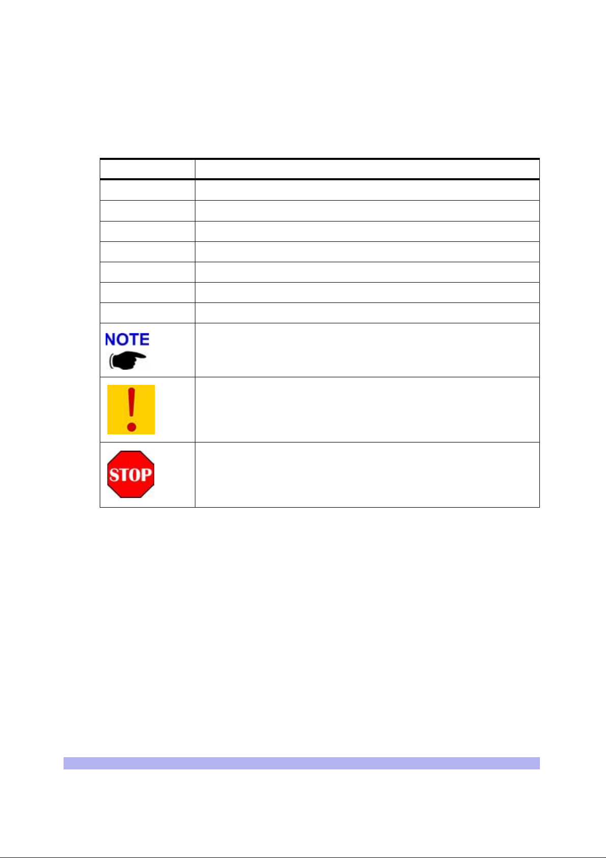
Conventions Used in this Manual
The following type and style conventions are used in this manual:
Table 1 Conventions Used in This Manual
Convention Meaning
Body text
Used for regular body text
Bold Indicates a menu or button choice
Command Indicates computer gene ra ted text and prompts
User Input Indicates user input
<hostname> In command syntax, indicates user-specified command line parameters
<variable> In body text, indicates user-specified command line parameters
[BRACKETS] Indicates a key on the keyboard or instrument
Provides relevant additional information
Provides important warning information that may affec t operation of or
maybe a potential threat to the system
Used to tell the reader to
important instructions that are vital to prevent equipment or software
damage
STOP what they are doing and to read
xii UltraWAVE BTS Installation and Commissioning Guide, Release 6.5A
Page 13

One
Unpacking and Configuration Veri fication
This chapter provides instructio ns for opening the shipping container and inspecti ng the contents.
When you have completed the procedu res in this chapter you will have confirm e d that the hardware
arrived undamaged, and that everything you ordered is present and configured correctly.
The procedures in this chapter include:
• Unpacking and inspecting the system. See Section 1-1.
• Inspect the system identification label and verify that this is the system you ordered. See
Section 1-2.
• Inspect the system components, verify and record the part numbers. See Section 1-3.
1-1 Unpacking and Inspecting
Your interWAVE system was packed with great care, and all containers were inspected before shipment.
Upon receipt of these packages, immediately inspect the outside of the shipping containers. If there is
any visible damage, insist that a representative of the carrier be present when unpacking the contents.
10000
Carefully inspect the system as it is unpacked. If any damage, such as dents or broken connections, is
noticeable immediately notify the car rier as well as interWAVE Customer Servi ce.
Store the shipping containers for future use. If the unit has to be returned for upgrade or service, the
specially designed shipping containers assure adequate protection for the equipment. If for some
reason the contai ner s ar e n ot r eusa b le or if they are misplaced, please contact interWAVE to order new
containers.
The UltraWAVE BTS is shipped pre-configured in a locking cabinet assembly, shown in Figure 1-1.
Unpacking and Configuration Verification 1
Page 14
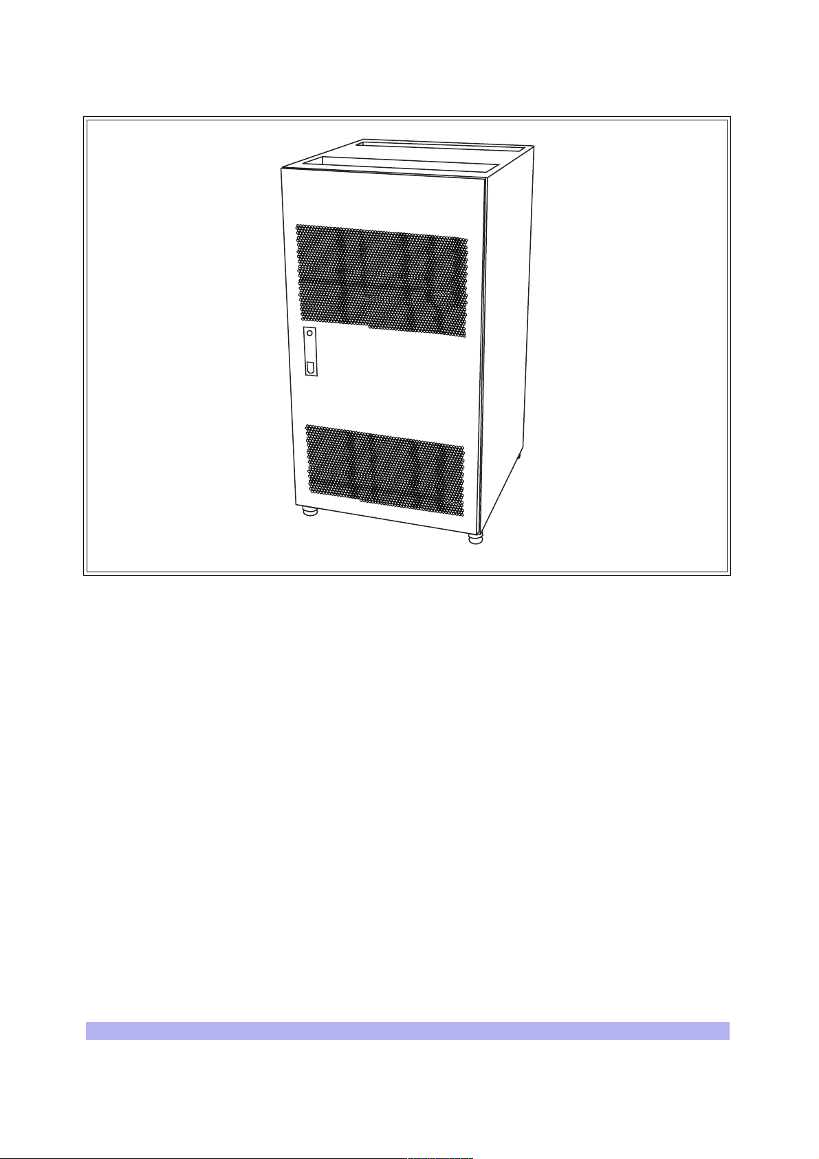
Figure 1-1 Locking Cabinet
Doors are provided for access to the front and rear of the internal assemblies. To open the doors:
1 Insert the key provided into the lock and turn to unlock.
2 Depress the lock mechanism to release the door latch handle.
3 Turn the door handle to unlatch and open the door.
IW007302
2 UltraWAVE BTS Installation and Commissioning Guide, Release 6.5A
Page 15

1-2 Inspect Components and Record Part Numbers
The UltraWAVE BTS is tested with all cards and modules installed in the chassis as ordered by t he
customer. In this section you will:
• Identify and record part and serial numbers
• Determine your system configuratio n
The unit is shipp ed assembled to your location. The as sem bl ed c abi net and subracks are pre-cabled for
your configuration with the exception of the power su pplies which will need to be installe d. The
individual components of the unit include:
• Cabinet (20U) with locking doors and external I/O int erface ports
• RF subrack assembly
• Baseband subrack assembly
• Power supply subrack assembly
• PC cards and blank panels
• RF cards and modules
• Internal cabling
• Power supply modules
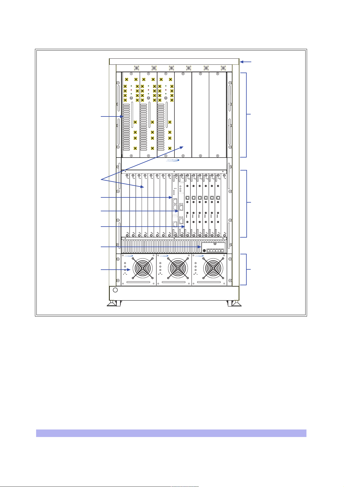
These components appear assembled without internal cabling in Figure 1-2.
Unpacking and Configuration Verification 3
Page 16
01 23 54
ANT
DIV
PWR
FLT
RX1
ON LINE
RX2
ON
RX3
OFF
RX4
MAIN
MAIN
DIV
PWR
FLT
RX1
RX1
ON LINE
RX2
RX2
ON
RX3
RX3
OFF
RX4
RX4
ANT
ANT
ANT
ANT
ANT
MAIN
DIV
PWR
FLT
RX1
RX2
RX3
RX4
RX1
RX1
ON LINE
RX2
RX2
ON
RX3
RX3
OFF
RX4
RX4
Cabinet (20U)
RF modules
Blank panels
Processor card
E1 or T1 trunk card
TRX cards
Clock module
Power supply modules
OUTPUT
OFF ON
RF subrack
TX1
DET
PA1
IN
TX2
DET
PA2
IN
DET
DET
PA1
PA1
IN
TX2
DET
PA2
IN
IN
TX2
DET
PA2
IN
TX1
TX1
012345678
IIIIIIIIIIIIIIIIIIIIIIIII
P/N XXXXXX
PWR
ON
LINE
PWR
FLT
ONLINE
FLT
120 OHM
SCN
ENET
ALARMS
12
CON
PORT 0
ALARMS
IIIIIIIIIIIIIIIIIIIIIIIII
P/N XXXXXX
12
IIIIIIIIIIIIIIIIIIIIIIIII
S/N XXXXXX
PORT 1
IIIIIIIIIIIIIIIIIIIIIIIII
S/N XXXXXX
INPUT
FAULT
OUTPUT
OFF ON
INPUT
FAULT
TX
TX
TX
OUT
OUT
OUT
13 MHZ
13 MHZ
13 MHZ
CLK
CLK
CLK
RX-A
RX-A
RX-A
DET
DET
DET
IN
IN
IN
PWR
PWR
PWR
ON LINE
ON LINE
ON LINE
FLT
FLT
FLT
RX-B
RX-B
RX-B
INPUT
OUTPUT
FAULT
OFF ON
TX
TX
TX
OUT
OUT
OUT
13 MHZ
13 MHZ
13 MHZ
CLK
CLK
CLK
RX-A
RX-A
RX-A
DET
DET
DET
IN
IN
IN
PWR
PWR
PWR
ON LINE
ON LINE
ON LINE
FLT
FLT
FLT
RX-B
RX-B
RX-B
assembly
Baseband subrack
assembly
Power supply
subrack assembly
IW006301
Figure 1-2 UltraWAVE BTS Components
1-2.1 Id entifying the System Configuration
Many configurations of the UltraWAVE BTS are available, from an omni one TRX (O1) to a three sector
two TRX per sector (S222) system. Use this section to verify the configuration of your BTS.
1 Locate the main configuration label on the exterior of your shipping container as shown in
Figure 1-3.
This configuration label details the system configurat ion and all of the modules an d cards
contained in the system.
4 UltraWAVE BTS Installation and Commissioning Guide, Release 6.5A
Page 17
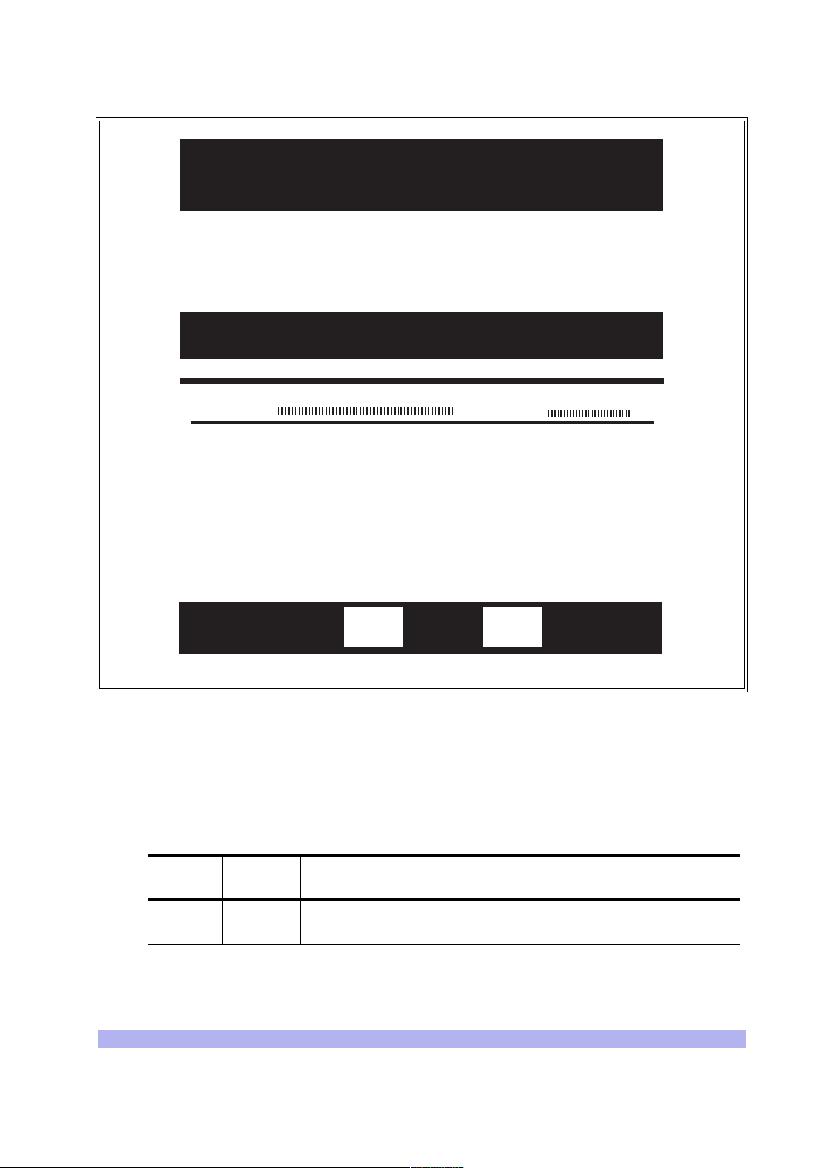
interWAVE Communications
312 Constitution Drive
Menlo Park, CA 94025-1164 USA
Ship To
Your Company
123 Main St.
Your Town, Province
Country
Equipment List
Model:
part number
xxxxxx-xxx
xxxxxx-xxx
xxxxxx-xxx
xxxxxx-xxx
xxxxxx-xxx
xxxxxx-xxx
AUACS241855075223A
module or card description
module or card description
module or card description 00xxxxxxx
module or card description 00xxxxxxx
module or card description 00xxxxxxx
module or card description 00xxxxxxx
module or card description 00xxxxxxx
- UltraWAVE BTS
SALES ORDER# XXXXXX
S/N:
000xxxxx
serial number
00xxxxxxx
Box
Figure 1-3 Main Configuration Label
2 Locate the model number and using Table 1-1 decode the first seven digits for the chassis
type and system c onfiguration of th e BTS.
The first four letters denote the type of interWAVE system, in this case an UltraWAVE BTS.
The next two o r three digits denote the BTS configuration.
Table 1-1 Model Number Details
Digit
Location
First four
letters
Contents Configuration
AUAC UltraWAVE BTS
of
IW007301
Unpacking and Configuration Verification 5
Page 18

Table 1-1 Model Number Details (continued)
Digit
Location
Next two
or three
digits
Contents Configuration
O1 Omni single TRX (O1); 50 watts, 2 antennas
O2 Omni two TRX (O2); 50 watts, 2 antennas
O3 Omni three TRX (O3); 25 watts, 2 antennas
O4 Omni four TRX (O4); 25 watts, 2 antennas
O5 Omni five TRX (O5); 15 watts, 2 antennas or 25 watts, 3 antennas
O6 Omni six TR X (O6); 15 watts, 2 antennas or 25 watts, 3 antennas
S11 Two sector, one TRX per sector (S11); 50 watt, 4 antennas
S13 Three sector, one TRX per sector (S111); 50 watt, 6 antennas
S21 Two sector, two TRXs per sector (S22); 50 watt, 4 antennas
S22
S23
S24 Three sector, two TRXs per secto r (S 22 2); 50 watt, 6 an tenn as
Three sector, two TRXs in one sector and one TRX in two sectors
(S211); 50 watt, 6 antennas
Three sector, two TRXs in two sectors and one TRX in one sector
(S221); 50 watt, 6 antennas
S32
S33 Two sector, three TRXs per sector (S33); 25 watt, 4 antennas
S41
Two sector, th ree TRXs in one sector and two in the other (S32); 25
watt, 4 antennas
Two sector, four TRXs in one sector, two in the ot her (S42); 25 watt,
4 antennas
Using the example in Figure 1-3, the model number is AUACS24 which corresponds to an
UltraWAVE BTS configured for three sectors with two TRXs per sector (S222).
3 Record your model number and co nf iguration in the Installation Checklist.
1-2.2 Identifying Module Part and Serial numbers
The factory plac es up to four configuration labels on the f r ont of each BTS card, module, and ch a ssis to
help identify the system configuration . The labels identify the:
• Part description
• Part number
• Revision or dash number
• Serial number
An example of the configuration labe ls appears in Figure 1-4:
6 UltraWAVE BTS Installation and Commissioning Guide, Release 6.5A
Page 19
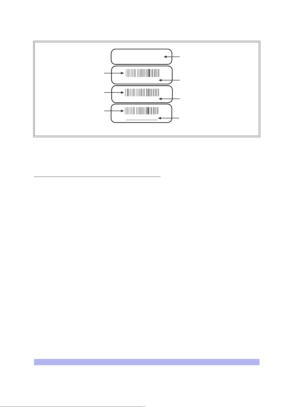
E1
LH, 2 PORT, ETH
Barcode identifier of
the part number
P/N 340127
Barcode identifier of
the rev number
-200
Barcode identifier of
the serial number
S/N 00719500
Figure 1-4 Sample Configuration Labels
The part numbers on the BTS car ds and mo dules s hould be compar ed to the m ain confi gurati on label as
instructed in the following sections.
Part Numbers, Revision Numbers and Serial Numbers
The verification proce dures requ ire y ou to re cor d each components’ part number, revision number and
serial number. These numbers are displayed on labels attached to th e front plate of each component:
Description of part
Part number
Dash or revision number
Serial number
IW048901
• Part Number -- The part number identifies the type of c omponent. All identical components
have the same part number. Part numbers use the format:
P/N NNNNNN
• Revision Number -- Revision numbers record minor changes in design. Revision numbers
use the format:
-NNN
• Serial Number -- Each individual component has its own unique serial number. Serial
numbers use the format:
S/N NNNNNNNN
Unpacking and Configuration Verification 7
Page 20

1-3 Verifying and Documenting Cards and Modules
The cabinet contains three subrack assemblies:
• The RF subrack contains the BTS RF modules which are responsible for RF power amplifica-
tion, duplexing and combining when requi r ed for each c onf iguration.
• The baseband subrack assembly contains the main processing, trunking and TRX cards.
• The power supply subrack assembly contains up to three power supply modules.
1-3.1 Required Equipment
To verify and record your system configuration, you need:
• A copy of the Shipping Checklist . It should be one of the papers inside the shipping
container.
• A copy of Checklist 2
1-3.2 RF Subrack Assembly
The RF subrack pr o vid es s i x slots, starting on the left wi th sl ot 0. Depending on your BTS configurat i on ,
up to three slots will be required for RF modules. These modules are shipped pre-installed and cabled
from the factory.
1 Locate the configuration part and serial numbers on your RF modules. Figure 1-4 illustrates a
sample of these labels.
2 Write down the pa rt numbe r, re vis ion n umber a nd seri al number i n the Ins talla tion Check list.
3 Compare the part numbers to the RF module part numbers on the main configuration label
and shipping ch ecklist.
1-3.3 Baseband Subrack Assembly
The baseband subrack provides nine slots, starting on the left with slot 0. The following table shows the
card cage assignments in the baseband subrack assembly:
Table 1-2 Card Cage Slot Assignments
Card Slots
Processor card 0 1 This is an ICP processor card.
E1 or T1 1 1 E1 or T1 card provides 2 E1 or T1 lines
TRX 2, 3, 4, 5, 6, 7 1 Each TRX manages 8 radi o channels.
Use the following procedure to identify and record your system components. See Figure 1-5 for
component locations:
Width
(Slots)
Function
8 UltraWAVE BTS Installation and Commissioning Guide, Release 6.5A
Page 21
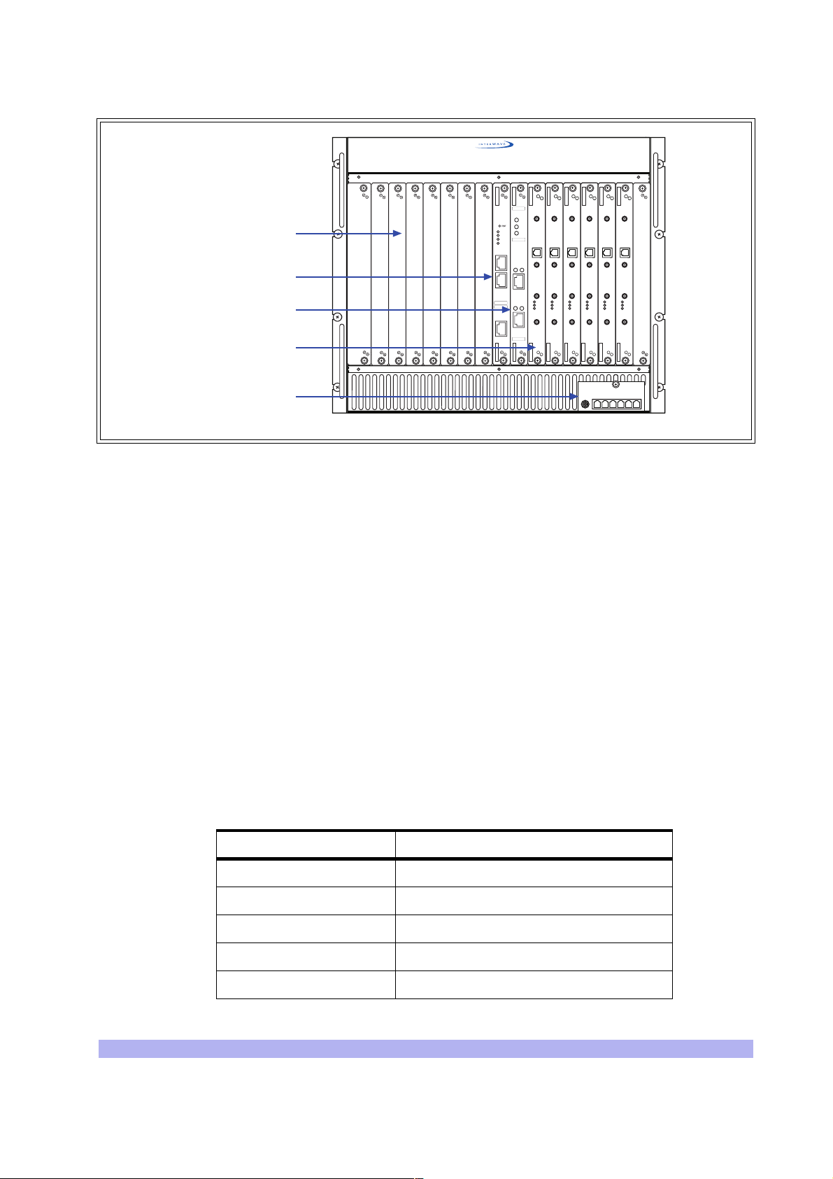
Blank panels
Processor card
E1 or T1 trunk card
TRX cards
Clock module
Figure 1-5 Baseband Subrack Assembly
1 Locate slot 0 and write down the processor card part number, revision numbe r and serial
number in the installation checklist. The processor card part number for the BTS is 340150.
2 Slot 1 should contain an E1 or T1 card. Verify that the part number on the card identifies the
card as the correct type, as specified by the main configuration label, and write down the
part number, re vision number and serial number in the installation checklis t.
012345678
IIIIIIIIIIIIIIIIIIIIIIIII
P/N XXXXXX
PWR
ON
LINE
PWR
FLT
ONLINE
FLT
120 OHM
SCN
ENET
ALARMS
12
CON
PORT 0
ALARMS
IIIIIIIIIIIIIIIIIIIIIIIII
P/N XXXXXX
12
IIIIIIIIIIIIIIIIIIIIIIIII
S/N XXXXXX
PORT 1
IIIIIIIIIIIIIIIIIIIIIIIII
S/N XXXXXX
TX
TX
TX
OUT
OUT
OUT
13 MHZ
13 MHZ
13 MHZ
CLK
CLK
CLK
RX-A
RX-A
RX-A
DET
DET
DET
IN
IN
IN
PWR
PWR
PWR
ON LINE
ON LINE
ON LINE
FLT
FLT
FLT
RX-B
RX-B
RX-B
TX
TX
TX
OUT
OUT
OUT
13 MHZ
13 MHZ
13 MHZ
CLK
CLK
CLK
RX-A
RX-A
RX-A
DET
DET
DET
IN
IN
IN
PWR
PWR
PWR
ON LINE
ON LINE
ON LINE
FLT
FLT
FLT
RX-B
RX-B
RX-B
IW007303
The BTS will contain one of three types of E1 or T1 cards:
• 75 Ohm E1 -- Part Number 340122-075
• 120 Ohm E1 -- Part Number 34 0122-120
• 100 Ohm T1 -- Part Number 34 0122-100
3 Verify that your system has the correct number of TRX cards as determined by the main
configuration label.
4 Using Table 1-3, verify that they are in the correct slots. TRX cards fill the card cage
assembly from left to r i ght . For exa m ple, i f y our con fi gur a ti on ha s th r ee TRX s , slots 2, 3 and
4 would contain the TRXs.
Table 1-3 TRX Slot Assignments
TRX Card # Slots
12
23
34
45
56
Unpacking and Configuration Verification 9
Page 22
Table 1-3 TRX Slot Assignments
TRX Card # Slots
67
Note: Systems equipped with less than six TRXs will have blank panels
covering the empty slots.
5 For each TRX card, write down the part number, revision number and serial number in the
installation checklist.
6 Verify that all empty slots have blank panels covering them.
7 Check the shipping invoice and verify that the system has the correct number of power
modules (2 or 3). If the third power module is not installed, verify that the slot is covered by
a blank panel.
8 For each power mo dule, write down the part numb er, revision number and seri a l n u m ber in
the installation checklist.
9 Verify that the clock module is installed. Write down its part number, revision number and
serial number in the installation checklist.
10 Verify all empty sl ots are covered by blank panels. These are necessary for cooling and to
meet RF emission standards.
1-4 Internal Cabling Overview
Cabling inside the BTS cabinet i s routed to connectors accessible on the outside of the cabinet
assembly. The internal cabling connects the E1 or T1 card to the external interface cable plate interface.
Antenna connections are also routed interna lly to provide an N-type connector on the top of the
cabinet.
The internal cabling of the BTS depends on the configur ation ordered by th e c ustomer. It is completed
by the manufacturer. Due to its complexity, it is not recommended for you to move or disconnect
internal cabling. Schematics of the int er nal RF cabling are provided in Appendix 1.
Extreme care should be used when working around SMA cables, as
misalignment or loosening of the cable with the connectors can
damage both parts and degrade the cable's performance.
Proceed to Chapter Two to install your BTS.
10 UltraWAVE BTS Installation and Commissioning Guide, Release 6.5A
Page 23

Two
This chapter provides instructions for installing and configuring the hardware. This includes:
• Verifying site requirements
• Mounting the chassis in i ts permanent location
• Configuring the E1 or T1 trunk card(s)
• Making the external connections to the BTS
2-1 Site Requirements
Before a si te is chosen or equipment installed, a site survey must be carried o ut. The site survey
checklist assists the surveyor with the inspection and the collection of site specific information such as
environmental conditions, electrical requirements, and mechanical requirements
The site survey checklist must be completed before installation begins. Note that the necessary steps
for site readiness are listed in Checklist 1.The interWAVE Network Implementation Manual
additional det a iled site requirements.
Installation
20000
provides
The site readiness c heck l i st as sists the field service engineer or operator to ensure that the site is ready
for equipment installatio n. It includes information about:
• Environmental conditions
• Electrical requirements
• Chassis require m ents
The site readiness checklist is located in Checklist 1, it must be completed as part of the installation
process.
2-1.1 Environmental Conditions
The BTS is designed to operate indoors only. To facilitate long-term operability an d durability of the
BTS, observe specific environmental constraints.
Before installing the BTS, ensure that the operating environment maintains a temperature within the
range shown in Table 2-1.
Make sure the ambient temperature around the unit (which may be
higher than the room temperature) is within the limit specified for the
unit.
Installation 11
Page 24

Table 2-1 Operating Environment
Humidity
(non-condensing)
Maximum 90% 55 degrees 131 degrees
Minimum 10% -5 degrees 23 degrees
2-1.2 Electrical R equirements
The BTS is specifie d to op er at e on either AC or DC power. Requirements for the BTS are dependent on
the number of TRX cards supported.
Power Options
Main power supply options for the BTS are:
• 110 VAC, 50-60 Hz
• 220 VAC, 50-60 Hz
• -48 VDC
Table 2-2 shows the typical current requirements for the BTS AC power mains.
Table 2-2 Input Power Requirements
Product
configuration
Temperature
(Celsius)
Requirement for 120 or 220 VAC
Temperature
(Fahrenheit)
One TRX 410 watts
Two TRXs 715 watts
Three TRXs 1010 watts
Four TRXs 1320 watts
Five TRXs 1630 watts
Six TRXs 1925 watts
Table 2-3 Power Specifications
Power Requirements Specification
BTS voltage range: 115 VAC 90 to132 VAC, 47 to 63 Hz
BTS power protection: 115 VAC Dedicated 20 amp circuit breaker
BTS voltage range: 230 VAC 187 to 264 VAC, 47 to 63 Hz
BTS power protection: 230 VAC Dedicated 10 amp circuit breaker
BTS voltage range: -48 VDC -41 to -60 VDC
12 UltraWAVE BTS Installation and Commissioning Guide, Release 6.5A
Page 25
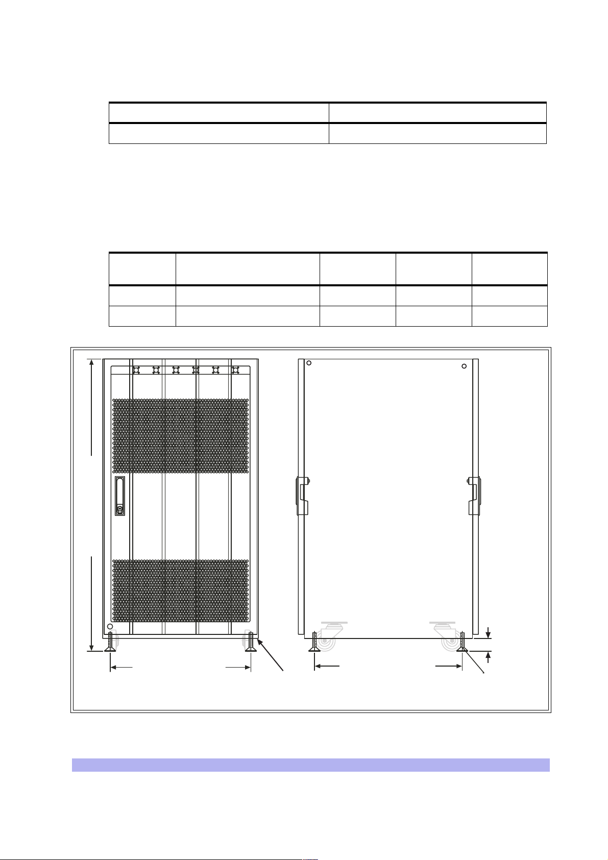
Table 2-3 Power Specifications (continued)
WHEEL_FV
CAB_F
RUBFE
RUBFE
Power Requirements Specification
BTS power prote ction: -48 VDC dedicated 45 amp fuse/circuit breaker
2-1.3 Chassis Requirements
Before installing the BTS, ensure that adequate clearing space is allowed around the unit. The BTS
should be installed away from salt spray and in an area where there are min imal vibrations. Table 2-4
shows the dimensions of the BTS. For detailed cabinet dimensions, see Sect ion 2-2.
Table 2-4 BTS Cabinet Dimensions
Weight
(Maximum Configuration)
Height Width Depth
Metric 213 Kg 105.1cm 56.0 cm 64.77 cm
Imperial 470 lbs 41.38 inches 22.05 inches 25.5 inches
10 32 54
41.375 in. [105.09 cm]
DOOR_
DOOR_
FV
CAB_F
V
WHEEL_FV
RUBFE
ET
WHEEL_FV
RUBFE
ET
19.925 in. [50.61 cm]
SV
CAB_S
WHEEL_SV
V
RUBFE
ET
20.925 in. [53.15 cm]
M10 Tap Holes
(each corner)
WHEEL_SV
RUBFE
ET
M12-1.75
(each corner)
DOOR_
SV
1.808 in
[4.59 cm]
IW008301
Figure 2-1 Cabinet Dimensions
Installation 13
Page 26
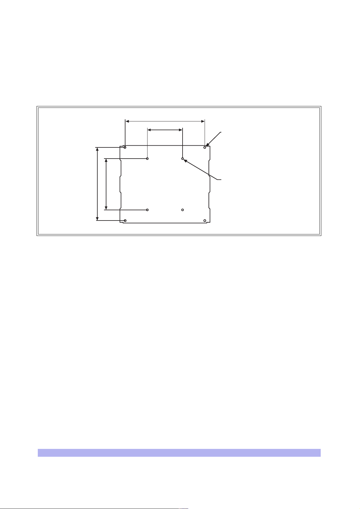
2-2 Mounting the BTS Chassis
The BTS chassis sho uld be mount ed on a concre te pa d of s uffic ien t densi ty t o supp ort t he weig ht of t he
cabinet assembly. Alignment pins may be installed in the concrete pad at the locations provided in
Figure 2-2. The alignment pins should be 0.5 inch (1.27 cm) in diameter and protrude from 4.1 in. to
4.4 in. (10.41 cm to 11.18 cm) from the concrete pad.
22.63 in. [57.48 cm]
[25.40 cm]
14.567 in.
[37.00] cm
20.898 in. [53.08 cm]
10.00 in.
Rubber feet
Mounting hole
M16-2 x4 places
Alignment holes
0.551 in. [1.40 cm]
IW021301
Figure 2-2 Cabinet Footprint
Enough clearance should be provided from the front and back of the cabinet to fully open the doors.
This requires at least 24 inches (61 cm) from the front and rear doors. The minimum clearance required
on either side of the cabinet is 4.5” (11.4 cm) and the minimum clearance required below the cabinet is
1.8 inches (4.59 cm). The mounting site should also have ample clearance for the trunk and antenna
cables to be attached to the connectors at the top of the cabinet.
The required footprint for your cabinet installation must be at least 73.5 inches (186.7 cm) by 31.5
inches (80 cm). Be sure there is sufficient airflow around the unit.
14 UltraWAVE BTS Installation and Commissioning Guide, Release 6.5A
Page 27
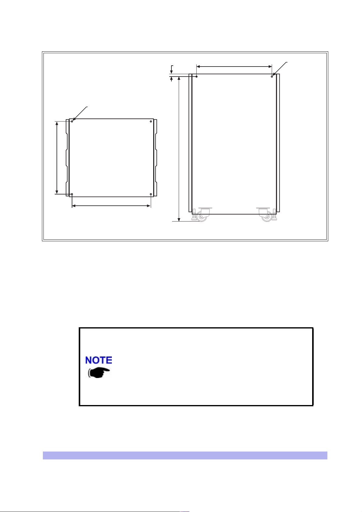
20.547 in.
[52.19 cm]
Tapped hole
M10-1.5 x4 places
22.280 in.
[56.59 cm]
0.750 in.
[1.91] cm
40.904 in.
[103.90 cm]
21.280 in.
[54.05 cm]
Tapped hole
M10-1.5
x4 places
Figure 2-3 Cabinet Dimensions
The cabinet is mounted on casters and may be carefully moved from the unpacking site to its final
mounting location. The cabinet has four rubber which will raise the cabinet off of the castors. The
dimensions for the engagement height of the rubber feet is shown in Figure 2-1. If you have alignment
pins mounted in your concrete pad, use the procedure in this section.
If you do not have the alignment pins, Figure 2-3 illustrates the location of eight M10 tap holes which
may be used for addition al mount ing stu ds, eye hooks or angle bra ckets for securi ng t he BTS cabinet in
its final location.
• Make sure the ambient temperature around the unit (which may be
higher than the room temperature) is within the limit specified for the
unit.
• Make sure there is sufficient airflow around the unit.
• Make sure electrical circuits are not overloaded - consider the
nameplate rating of all the connected equipment, and make sure you
have over current protection.
• Make sure the equipment is properly grounded.
• Make sure no objects place on top of unit.
Cabinet (side)Cabinet (top)
IW021302
Installation 15
Page 28
Required Materials
• Angle brackets
• Four M10 machine screws and washers
Required Tools
• 15 mm open end wrench
Installation Instructions
1 Move the cabinet into its final location. If using alignment pins to prevent movement, move
the cabinet into position over the pins.
2 Lower the each of the rubber feet until each reaches the concrete pad.
3 Using the 15 mm open end wrench, lower each foot until the casters are raised from the
concrete floor, approximately 0.25 in. (0.65 cm).
4 Remove the casters from the bottom of the cabinet.
5 Lower the cabinet to within 4.1 in. to 4.4 in. (10.41 cm to 11.18 cm) of the concrete pad. If
you are using alignment pins, lower the cabinet until the pins should enter the alignment
holes no more than 0.25 in. (0.6 cm). Do not lowe r the cabinet too far over alignment pins
as they may puncture internal components.
6 Secure locking nuts on foot studs.
7 Secure the cabinet using customer-provided 10 mm studs.
Rack Mount Advisory
To prevent bodily injury when mounting or servicing this unit in a rack, you must take specia l
precautions to ensure that the system remains stable. The following guidelines are provided to ensure
your safety:
• This unit should be mounted at the bottom of the rack if it is the only unit in the rack.
• When mounting this unit in a partially filled rack, load the rack from the bottom to the top
with the heaviest comp onent at the bottom of the rack.
• If the rack is provided with stabilizing devices, install the stabilizers before mounting or
servicing the unit in the rack.
Attention: Pour év iter tou te bl essure corp orell e pend ant l es opér ati ons de mo ntage ou de ré parat ion de
cette unité en casier, il convient de prendre des précautions spéciales afin de mainten ir la stabilité du
système. Les directives ci-dessous sont destinées à assurer la protection du personnel :
You may use the additional M10 tap holes to secure the cabinet as
site-specific conditions allow.
• Si cette unité constitue la seule unité montée en casier, elle doit être placée dans le bas.
16 UltraWAVE BTS Installation and Commissioning Guide, Release 6.5A
Page 29

• Si cette unité est montée dans un casier partiellement rempli, charger le casier de bas en
haut en plaçant l'élément le plus lourd dans le bas.
• Si le casier est équipé de dispositifs stabilisateurs, installer les stabilisateurs avant de monter
ou de réparer l'unité en casier.
Warnung: Zur Vermeidung von K örp erverletzung beim Anbringen oder Warten dieser Einheit in einem
Gestell müssen Sie besondere Vorkehrungen treffen, um sicherzustellen, daß das System stabil bleibt.
Die folgenden Richtlinien sollen zur Gewährleistung Ihrer Sicherheit dienen:
• Wenn diese Einheit die einzige im Gestell ist, sollte sie unten im Gestell angebracht werden.
• Bei Anbringung dieser Einheit in einem zum Teil gefüllten Gestell ist das Gestell von unten
nach oben zu laden, wobe i das schwerste Bauteil unten im Gestell anzubringen ist.
• Wird das Gestell mit Stabi lisierungszubehör geliefert, sin d zuerst die Stabilisatoren zu in stall-
ieren, bevor Sie die Einheit im Gestell anbringen oder sie warten.
Installation 17
Page 30
2-3 Configuring the E1 or T1 Trunk Card
This section describes how to configure E1 or T1 trunk cards.
These procedures designed for E1 or T1 cards that are shipped pre-configured in a system. To
configure E1 or T1 card s that a re ship ped as confi gured or unconfigured replacements, see Ap pendix 1.
Your system is shipped from the manufacturer configured with the correct cards for your site-specific
application. These can be 100 Ohm T1, 75 Ohm E1, or 120 Ohm E1. All cards are shipped with th e
appropriate connectors.
Cable runs of greater than 600 meters (1968 feet) are not supported
directly from the card. If you are attempting a longer cable run between
interWAVE chassis please contact Customer Service to determine if you
need a repeater for your application.
Table 2-5 list s the cards and the procedures that apply to each card type.
Table 2-5 Trunk Cards and Procedures
Label Description Operation
75 Ohm 75 Ohm E1 board
120 Ohm 120 Ohm E1 Board No configuration is required
100 Ohm 100 Ohm T1 Board
Set the ground to the Transmit or Receive side
using the jumpers. See Section 2-3.1
Configure the DIP switch based on cable length
to the DSX-1 demarcation point. See
Section 2-3.2.
NOTE: No configuration is required unless
connecting to a DSX1 demarcation point greater
than 133 ft.
2-3.1 Configure Ground Jumpers on 75 Ohm E1 Cards
Two types of dual port 75-Ohm E1 cards exist. They are differentiated only by their connector types—
either BNC or RJ-45 — on the front pa nel of the card.
1 Open the front cabinet door and locate the 75 Ohm E1 card in the baseband subrack
assembly.
2 Identify your E1 card and proceed to the appropriate subsection. For RJ-45 cards, continue
with the procedure below. For BNC cards, proceed to “BNC Connector Cards” on page 22.
18 UltraWAVE BTS Installation and Commissioning Guide, Release 6.5A
Page 31

PWR
ON
LINE
FLT
ALARMS
12
E1-0
PWR
ON
LINE
FLT
RS-232
RX
Figure 2-4 Identify 75 Ohm E1 Cards
RJ-45 Connector Cards:
1 Ensure that anti-static precautions are taken.
2 Make note of the orientation of the cables and disconnect them from the selected card.
3 Using a Phillips screwdriver, fully loosen the two screws located at the top and bottom of the
card.
PORT 0
ALARMS
12
PORT 1
RJ-45
E1-1
BNC
IW093203
TX
RX
TX
4 Remove the card by firmly pulling the two white tabs locat e d at the top and bottom of the
card.
5 See Figure 2-5 to locate jumpers P8 through P11.
6 Set the signal grounding to the Transmit or Receive Side.
Jumpers P8, P9, P10 and P11 control the signal grounding. Placing the jumper across Pins 1
and 2 sets the corresp onding ground; otherwise the jumper shou ld be pl a ced a c ros s Pi ns 2
and 3.
The following table shows the jumper assignments:
Installation 19
Page 32

Table 2-6 Ground Jumpers
Ground Selection Port Jumper Positions
Receive Side
Transmit Side
Port 0 P8 = 1 to 2 P9 = 2 to 3
Port 1 P10 = 2 and 3 P11 = 1 and 2
Port 0 P8 = 2 to 3 P9 = 1 to 2
Port 1 P10 = 1 and 2 P11 = 2 and 3
interWAVE recommends grounding the receive (RX) side on 75 Ohm boards.
Only one side of the transmission link should be grounded. To ensure
that only the one side is grounded you should check the settings at the
far end of the E1 transmission link when possible. These settings should
be identified by experie nced personnel.
7 Place the card into the slot and slide in the card until it completely rests inside the slot. Push
the card firmly into place.
8 Using a Phillips screwdriver, tighten the two captive screws into the chassis through the
trunk card.
20 UltraWAVE BTS Installation and Commissioning Guide, Release 6.5A
Page 33

Figure 2-5 shows the location of the grounding jumpers
J7
12 435678
ON
RX
Ground
Port 0
Ground
RX
Ground
Port 1
Ground
TX
TX
RJ45
RJ45
P8P11P10 P9
2940
FUSE
FUSE
FUSE
FUSE
FUSE
FUSE FUSE
FUSE
555-
RELAY
+
RELAY
+
RELAY
+
RELAY
+
2940
555-
NONC
NONC
NONC
NONC
1:1.36
PE68822
1:2
1:2
PE68822
1:1.36
Jumper
Item No.0015
61
X
T
41
61
X
T
41
80
RX
BT-8370
80
RX
BT-8370
1
..... HOST .....
21
1
..... HOST .....
21
Jumper Position 1,2
For P8-P11
IW068004
Figure 2-5 Ground Jumpers (P8 through P11)
Installation 21
Page 34

BNC Connector Cards
By placing a jumpe r between pins 1 a nd 2 of headers P4 (port 1) and P6 ( port 2), t he outer c onductor of
the dual port BNC 75 Ohm E1 card is grounded. This adheres to the ITU G.703 specification, which
states that the receive coaxial pair must be floating, but with the option to ground.
The BTS is shipped with 4 jumpers in place which ground both the transmit and the receive coaxial pair.
It is mandatory that the transmit pair is grounded. However, whether the receive pair is grounded is
determined by the customer equipment to which th e BSC is connected.
The configuration of these jumpers can be changed at this point.
Tools Required
• Phillips screwdriver
• Electrostatic wrist strap, provided with the BTS
Procedure
1 Place the supplied electrostatic wrist st rap around your wrist. Attach the metallized tape of
the wrist strap to the closest ground, fo r example, to the chassis of the BTS.
2 Unscrew the 75 Ohm dual port E1 card from the chassis, and pull it halfway out.
3 Look for the four jumpers silk-screened P3, P4, P5, and P6, located next to the external
connectors on the dual port E1 card. See Figure 2-6
• A jumper connects pins 1 and 2 of P4 and P6. Th is ensures that the out er conductor is
grounded. It is mandatory that these jumpers be installed in this configuration.
• A jumper connects pins 1 and 2 of P3 and P5. Remove these jumpers if the receive
pair must be floating. Keep these jumpers inst alled if the receive pair is to be
grounded.
.
Jumper
Item No.0015
P3
Receive
J1
J2
P4
Transmit
P6
Transmit
J3
J4
P5
Receive
Jumper Position 1,2
For P3-P6
IW272806
Figure 2-6 Placement of the Jumper for Ports P3-P6
22 UltraWAVE BTS Installation and Commissioning Guide, Release 6.5A
Page 35

After the E1 card jumpers are checked for their correct placement, reinsert the dual port E1 card in the
chassis, and screw it into place.
2-3.2 Configure Cable Length DIP Switch Settings on T1 Cards
To configure the DIP switch settings on a T1 card:
1 Ensure that anti-static precautions are taken.
2 Make note of the orientation of the cables and disconnect them from the selected card.
3 Using a Phillips screwdriver, fully loosen the two screws located at the top and bottom of the
card.
4 Remove the T1 card by firmly p ulling th e two w hite tabs l ocated a t the to p and bo ttom of th e
card.
5 See Figure 2-7 to locate the DIP switch.
6 On T1 cards, the DIP switch setting is determined by the cable distance from the card to the
DSX-1 demarcation point. The following table provides the appropriate Port 0 and Port
DIP switch settings for DSX-1 d e marcation points located wi th in various cable distance
.
ranges
In Table 2-7, the first setting (0-133 ft.) is the default and should be
used for all T1 applications unless
point beyond 133 ft. When connecting two WAVEXpress chassis you will
always use the first setting regardless of distanc e (up to 600 m).
connecting to a DSX-1 demarcation
1
Table 2-7 T1 DIP Switch Settings
Port 0
Switch Setting
1-2-3-4
OFF-ON-ON-ON OFF-ON-ON-ON 0-133 (0-40.57)
OFF-OFF-ON-ON OFF-OFF-ON-ON 133-266 (40.57-81.13)
OFF-ON-OFF-ON OFF-ON-OFF-ON 266-399 (81.13-121.7)
OFF-OFF-OFF-ON OFF-OFF-OFF-ON 399-533 (121.7-162.57)
OFF-ON-ON-OFF OFF-ON-ON-OFF 533-655 (162.57-199.78)
Port 1
Switch Setting
5-6-7-8
Cable distance from T1 Card to
DSX-1 Demarcation Point
Feet (Meters)
Note: ON refers to the DIP switch pin being in the “UP” position and OFF refers to the DIP
switch pin being in the “DOWN” position. X = either ON or OFF.
7 Place the card into the slot and slide in the card until it completely rests inside the slot. Push
the card firmly into place.
8 Using a Phillips screwdriver, tighten the two captive screws into the chassis through the
trunk card.
Installation 23
Page 36

The following figure shows the location of the DIP switch.
ON
12 435678
J4
12 435678
ON
J6
Figure 2-7 Location of DIP switch on a Trunk Card
J8
J7
J9
IW180001
24 UltraWAVE BTS Installation and Commissioning Guide, Release 6.5A
Page 37

2-4 Connecting Power and Ground Cables
Use this section to c onnect your earth ground and power cables to the BTS cabinet.
2-4.1 Connecting the Grounding Cable
The cabinet should be grounded to the site earth ground ring. Complete the following to connect an
earth ground to the chassis.
1 Route a customer-supplied 10 AWG (2.5 mm) or larger copper wire to a grounding lug
inserted into one of the M10 tap holes shown in Figure 2-3.
2 Connect the other end of the lead stud to the closest grounding bus.
CAUTION: GROUNDING CIRCUIT CONTINU ITY IS VITAL FOR SAFE
OPERATION OF MACHINE. NEVER OPERATE MACHINE WITH
GROUNDING CONDUCTOR DISCONNECTED.
ATTENTION: UN CIRCUIT DE TERRE CONTINU EST ESSENTIEL EN VUE
DU FONCTIONNEMENT SÉCURITAIRE DE L'APPAREIL. NE JAMAIS METRE
L'APPAREIL EN MARCHE LORSQUE LE CABLE DE MISE À LA TERRE EST
DÉBRANCHE.
Warnung: Achtung , Hoher Ableitstrom! S chutzleiteranschluß vor dem
Netzanschluß herstelle n.
2-4.2 Connecting the Power Supplies
In this section, you will connect the BTS to your power source. Refer to the appropriate subsection to
make either AC or DC power connections.
Warning: This product relies on the building's installation for
short-circuit (overcurrent) protection. Ensure that a fuse or circuit
breaker no larger than 120 VAC, 15A U.S. (240 VAC, 10A int ernational)
is used on the phase conductors (all current-carrying conductors).
Attention Pour ce qui est de la protection contre les courts-circ uits
(surtension), ce produit dépend de l'installation électrique du local.
Vérifier qu' un fusible ou qu'un disjoncteur de 120 V alt., 15 A U.S.
maximum (240 V alt ., 1 0 A intern a tion al) es t ut il isé s ur les co nd uct eurs
de phase (conducteurs de charge).
Warnung Dieses Produkt ist darauf angewiesen, daß im Gebäude ein
Kurzschluß- bzw. Überstromschutz installiert ist. Stellen Sie sicher, daß
eine Sicherung oder ein Unterbrecher von nicht mehr als 240 V
Wechselstrom, 10 A (bzw. in den USA 120 V Wechselstrom, 15 A) an
den Phasenleitern (alle n strom fü h ren den Leitern) verwendet wir d.
Installation 25
Page 38

AC Operation
The BTS is shipped from the factory wi th the in terna l cablin g rout ed fro m the AC po wer s upp l y sub rack
assembly to a molex connector on the top rear of the cabinet. A power supply cable is included with the
BTS which should be used to connect to your AC power supply or battery backup system.
Make connections from the AC power supply to the cabinet as follows:
1 Verify the ground connection you made in Section 2-4.1 is secure.
2 Make sure that the power button located on all power supply modules is in the raised OFF
position. See Figure 2-8 for the location of the power supply power buttons.
INPUT
OUTPUT
FAULT
OFF ON
INPUT
OUTPUT
FAULT
OFF ON
ON/OFF Buttons
Figure 2-8 Power Supply ON/OFF Buttons
3 Plug the molex power connector into the power connection on the top of the cabinet.
Secure the connector by twistin g the connect or sleeve until the lines on the cable connector
and chassis connector align.
4 Plug the power cable into the electrical ma ins. Do not a pply power to th e chassis at this tim e.
Wait until you are performing th e off-line commissioning procedures in the next chapter.
CAUTION: THE POWER SUPPLY CORD IS USED AS THE MAIN
DISCONNECT DEVICE, ENSURE THAT THE SOCKET-OUTLET IS
LOCATED/INSTALLED NEAR THE EQUIPMENT AND IS EASILY
ACCESSIBLE.
INPUT
OUTPUT
FAULT
OFF ON
IW008302
ATTENTION: LE CORDON D'ALIMENTATION EST UTILISÉ COMME
INTERRUPTEUR GÉNÉRAL. LA PRISE DE COURANT DOIT ÊTRE SITUÉE
OU INSTALLÉE À PROXIMITÉ DU MATÉRIEL ET ÊTRE FACILE D'ACCÉS.
Warnung: Das Netzkabel dient als Netzschalter. Stellen Sie sicher, das
die Steckdose einfach zugänglich ist.
26 UltraWAVE BTS Installation and Commissioning Guide, Release 6.5A
Page 39

-48 VDC Operation
The BTS is shipped from the factory with the internal cabling routed from the DC power supply subrack
assembly to a molex connector on the top rear of the cabinet. A power suppl y cabl e is in cl uded with the
BTS which should be used to connect to your DC power supply or battery backup syste m .
Use the following procedure:
1 Verify the ground connection you made in Section 2-4.1 is secure. The cabinet power
supply is grounded through this connection. It is critical that this connection is made
properly.
2 Make sure that the power button located on all power supply modules is in the raised OFF
position. See Figure 2-8 for the location of the power supply power buttons.
3 Verify that the-48 VDC power source is off.
4 The -48 VDC power cable has two wi res fo r the pos itive ( +) connec tion and two wire s for the
negative (-) connection. This spreads the curr ent draw across two pins of the molex
connector for each connection.
The power main must be a Safe Extra-Low Voltage (SELV), -48 VDC
supply as defined in IEC950 and EN60950.
Attach the two positive (+) cables to the positive side of your -48 VDC power source.
5 Attach the two negative (-) cables to the negative side of your -48 VDC power source.
6 Plug the molex power connector into the power connecti on on the top of the cabinet.
Secure the connector by twistin g the connect or sleeve until the lines on the cable connector
and chassis connector align.
Do not use the DC power supply circuit breaker to apply power to the
chassis at this time. Wait until you are performing the off-line
commissioning procedures in the next chapter.
CAUTION: THE POWER SUPPLY CORD IS USED AS THE MAIN
DISCONNECT DEVICE, ENSURE THAT THE SOCKET-OUTLET IS
LOCATED/INSTALLED NEAR THE EQUIPMENT AND IS EASILY
ACCESSIBLE.
ATTENTION: LE CORDON D'ALIMENTATION EST UTILISÉ COMME
INTERRUPTEUR GÉNÉRAL. LA PRISE DE COURANT DOIT ÊTRE SITUÉE
OU INSTALLÉE À PROXIMITÉ DU MATÉRIEL ET ÊTRE FACILE D'ACCÉS.
Warnung: Das Netzkabel dient als Netzschalter. Stellen Sie sicher, das
die Steckdose einfach zugänglich ist.
Installation 27
Page 40

2-5 Connecting E1 or T1 Trunk Cables
External trunk cabling depends on the configuration that the customer ordered and the site-specific
requirements. These cables will be supplied by the customer. Failure to use electrically compliant T1 or
E1 cables may cause transmission errors. Please refer to the appropriate subsections to determine your
cable requirements.
The E1 or T1 trunk cables are routed internally from the E1 or T1 trunk card in the baseband sub rack
assembly to the top rear of the BTS cabinet. All three types of signaling (E1 75 Ohm, 120 Ohm and T1
100 Ohm) are termina ted at the cabinet with RJ-48C port connectors. The pinout of this connector is
illustrated in Figure 2-9.
E1 or T1 Port
Connector
Pin Numbers
Figure 2-9 Cabinet Trunk Port Pinout
2-5.1 E1 Cables
E1-75 Ohm
This is coaxial cable with a nominal impedance of 75 Ohm +/-5% at 1 MHz. The maximum allow able
cable distance depends directly on the insertion loss of the cable at 1 MHz. In this mode, the E1 trunk
card can accommodate up to 6 dB of cable loss.
E1-120 Ohm
8
7
6
5
4
3
2
1
Pin 8: PCB Signal Ground
Pin 5: Transmit Tip
Pin 4: Transmit Ring
Pin 2: Receive Tip
Pin 1: Receive Ring
IW009301
This cable is individually shielded twisted pair with a nominal impedance of 120 Ohm +/-5% at 1 MHz .
The maximum allowable cable distance depends directly on the insertion loss of the cable at 1 MHz. In
this mode, the E1 trunk card can accommodate up to 9 dB of cable loss.
Table 2-8 provides a de script ion of cables re quired fo r inst alla tion an d connect ion t o an E1 networ k, but
not supplied wit h the BTS:
28 UltraWAVE BTS Installation and Commissioning Guide, Release 6.5A
Page 41

Table 2-8 Customer-Supplied E1 Cabling
Cable Identity Cable Type Corresponding Cable Plug
E1, 120 Ohm Shielded, Twisted, 2- Pair RJ-48C, Male
E1, 75 Ohm Shielded, Twisted, 2-Pair RJ-48C, Male
Note: The number of cables required depends on the ordered configuration of the BTS.
Conversion Cables
If you are connecting into an existing E1 network with standard BNC or DSUP connectors, a conversion
cable for either the 75 Ohm or 120 Ohm will be required. To purchase these cables from interWAVE,
contact your local sales support representative.
Before connecting E1 lines to the BTS, it is assumed that the quality of
the lines has been verified. It is recommended that bit error ratio tests
-8
be completed to ensure that the BER is less than 10
.
J2
RECEIVE
TRANSMIT
J3
J2
BLUE/WHITE
WHITE/BLUE (R-TIP)
ORANGE/WHITE
WHITE/ORANGE
J3
Figure 2-10 75 Ohm BNC Conversion Cable
Figure 2-10 illustrates the pinout for an RJ-48C to 75 Ohm BNC conversion cable.
(R-RING)
(T-RING)
(T-TIP)
J1
Pin 1
Pin 8
J1
1
2
3
4
5
6
7
8
IW009302
Installation 29
Page 42

Pin 15 Pin 8
Pin 9
Pin 1
J2
Pin 1
Pin 8
J1
J2
11
3
9
1
BLUE/WHITE
WHITE/BLUE (R-TIP)
ORANGE/WHITE
WHITE/ORANGE
Figure 2-11 120 Ohm DSUB Conversion Cable
Figure 2-11 illustrates the p inout for the RJ-48C to DSUB 120 Ohm conversion cable.
2-5.2 T1 Cables
T1-100 Ohm
For T1 connections, the proper cable is individually shielded twisted pair with a nominal impedance of
100 Ohm +/-5% at 772 kHz. The maximum allowable cable distance depends directly on the insertion
loss of the cable at 772 kHz. The T1 card can accommodate up to 9 dB of cable loss. When using
22 AWG ABAM cable, 9 dB of loss is approximately 2000 feet. When using Belden type 9729 (with a
cable loss of 6 dB per 1000 feet at 7 72 kHz) the maximum cable di stance is approximately 1500 feet.
(R-RING)
(T-RING)
(T-TIP)
J1
1
2
3
4
5
6
7
8
IW009303
Table 2-9 provides a description of cables required for installation and connecti on to a T1 network, but
not supplied wit h the BTS:
Before connecting T1 lines to the BTS, it is assumed that the quality of
the lines has been verified. It is recommended that bit error rate tests
-8
be completed to ensure that the BER is less than 10
.
Table 2-9 Customer-Supplied T1 Cabling
Cable Identity Cable Type Corresponding Cable Plug
T1, 100 Ohm Shielded, Twisted, 2-Pair RJ-48C, Male
Note: The number of cables required depends on the ordered configuration of the BTS.
30 UltraWAVE BTS Installation and Commissioning Guide, Release 6.5A
Page 43

2-5.3 Connecting E1 or T1 Lines
All E1 or T1 cable routing should be installed per the site survey documentation in conjunction with the
information identified in the interWAVE Network Implementation Manual
.
• Using the approp riate customer-sup plied cables, connect the Abis interface E1 and/or T1
cables to the local E1 or T1 provider.
2-5.4 Direct Cabling Between Multiple UltraWAVE or WAVEXpress Systems
This section provides info rmation for cabling between WAVEXpress equipment. The external cabling
between your equipment will vary depending on the configuration of t he cable management assembly
of each chassis. This could consist of any combination of BNC, DSUB or RJ-48C connectors and either
E1 or T1 signaling.
The direct cabling between systems requires crossover cables (Tx to Rx,
and Rx to Tx), instead of the straight-through cabling used when
connecting syst ems through a radio or telephone provider network.
Using Cross-Over RJ-48C Cables
When connecting a shielded twisted pair crossover cable between two UltraWAVE or WAVEXpress
systems, the routing of the pins needs to comply with the cable mapping shown in Figure 2-12. The
RJ-48C cable connector may be of the conventional plastic body type with the shield and drain wires of
the cable connected to a pigtail to pin 8 (Signal Ground), which is internally grounded to the card.
However, a shielded cable plug may also be used, terminating the cab le shie ld to an integral metal shell
of the RJ-48 jack which then makes an electrical connection to the front panel when installed.
Figure 2-12 provides the pin assignments for the RJ-48C jacks.
Pin 5: Transmit Tip
Pin 4: Transmit Ring
Pin 2: Receive Tip
Pin 1: Receive Ring
T1 or E1 Port
Connector
8
7
6
5
4
3
2
1
PCB Signal
Ground
Pin Numbers
T1 or E1 Port
Connector
8
7
6
5
Pin 5: Transmit Tip
4
Pin 4: Transmit Ring
3
2
Pin 2: Receive Tip
Pin 1: Receive Ring
1
IW214901
Figure 2-12 Cable Mapping of RJ-48C Crossover Cable
Installation 31
Page 44

To connect two systems using RJ-48C cables, conn ect a cros sover c able (see Figure 2-12) from the port
1 of the first chassis to port 0 of the second chassis.
2-5.5 Cabling External BTSs
The BTS can also be connected to daisy-chained BTSs as described in Section 2-5.4. These
daisy-chained BTSs will download their operating software from the BSC into their flash memory upon
reboot. Some additional software configuration is also required to setup the operations and
maintenance link to the OMC. This ad ditional configuration of the OAM timeslots is required for
daisy-chained BTSs as discussed in Chapter Four.
2-6 Connecting Antennas
The cabinet assembly provides external access to the male N-type connectors for your external
antennas. Your ant enna ca ble shoul d termina te with a 90° N-typ e female co nnector o r an N-typ e female
to male elbow adapter may be used for a more convenient connection to the cabinet. Insertion loss for
the elbow type of connector is typically between 0.1 and 0.2 dBm.
The antenna cabling for the BTS can be configured in several ways depending on a number of factors
including the number of TRXs, number of antennas and use of diversity. Your site specific configuration
was determined during the netwo r k planning stage of implementation.
Table 2-10 Customer-Supplied Adapters and Cabling
Identity Cable Type Corresponding Cable Plug
Antenna cable (external) Coaxial N-type, Female
Adapter (optional) 90 degree elbow N-type Female to N-type Male
Note: The number of cables required depends on the ordered configuration of the BTS.
In the subsequ ent sections, each RF configurat ion is detailed from the RF module connector to the
internal RF connector. Figure 2-13 the relationship between the three connectors. The RF modules are
connected to the internal RF connecto rs at the factory and are pre-c onfigured for y our BTS
configuration.
External RF Connectors
(Top of Cabinet)
Internal RF Connectors
(with port number)
RF Module Connectors
01 23 54
ANT
ANT
MAIN
DIV
PWR
FLT
RX1
RX1
ON LINE
RX2
RX2
ON
RX3
RX3
OFF
RX4
RX4
ANT
ANT
MAIN
DIV
PWR
FLT
RX1
RX1
ON LINE
RX2
RX2
ON
RX3
RX3
OFF
RX4
RX4
ANT
ANT
MAIN
DIV
PWR
FLT
RX1
RX1
ON LINE
RX2
RX2
ON
RX3
RX3
OFF
RX4
RX4
IW009304
Figure 2-13 Antenna Cabling for Standard BTS Configurations
32 UltraWAVE BTS Installation and Commissioning Guide, Release 6.5A
Page 45

You will attach an elbow connector and your antenna cable to the external RF connector associated with
the intern al RF connector shown in the appropriate figure.
The subsequent sections ident ify the cable rou ting for th e different BTS anten na configurations that you
identified in Chapter One . Y ou must i ns tal l th e antennas such that the general population is kep t at least
164-inches from the ma in beam of the antenna. For more information of RF radiation properties of th e
UltraWAVE, refer to Section 2-6.17.
Proceed to the appropriate subsection to connect your site-specific antenna cable configuration.
All RF cabling must be completed with the chassis powered off and,
preferably, with the power cable disconnected from the cabinet.
Do not disconnect RF coaxial connectors on the interWAVE equipment
or antenna systems while the radio equipment is operating.
place any body part over or look into any RF connector while the radio
equipment is transmitting.
Radio frequency signal levels that give rise to hazardous radiation levels
can exist within the transmitter, power amplifiers, associated RF
multiplexers and antenna systems.
2-6.1 Omni 1 TRX (O1) Configuration
This is a 50 watt (47 dBm) two ant e nna configuration available in either 850 MHz or 900 MHz
frequencies. Connect your antennas as shown in Figure 2-14.
Never
Antenna connection
External RF connector
Internal RF connector
RF modules
Antenna 1
Diversity
ANT
DIV
Antenna 1
Main
1 2 3 4 50
ANT
MAIN
Figure 2-14 Antenna Ca bling for O1 Configuration
Not UsedNot Used Not Used Not Used
IW009305
Installation 33
Page 46

2-6.2 Omni 2 TRX (O2) Configuration
This is a 50 watt (47 dBm) two ant e nna configuration available in either 850 MHz or 900 MHz
frequencies. Connect your antennas as shown in Figure 2-15.
Antenna 1
Diversity
Antenna 1
Main
Antenna connection
External RF connector
ANT
MAIN
1 2 3 4 50
Internal RF connector
ANT
DIV
RF modules
Figure 2-15 Antenna Ca bling for O2 Configuration
2-6.3 Omni 3 TRX (O3) Configuration
This is a 25 watt (44 dBm) two ant e nna configuration available in either 850 MHz or 900 MHz
frequencies. Connect your antennas as shown in Figure 2-16.
Antenna 1
Diversity
Antenna 1
Main
Not UsedNot Used Not Used Not Used
IW009305
Antenna connection
Not UsedNot Used Not Used Not Used
External RF connector
Internal RF connector
ANT
RF modules
1 2 3 4 50
ANT
IW009306
Figure 2-16 Antenna Ca bling for O3 Configuration
2-6.4 Omni 4 TRX (O4) Configuration
This is a 25 watt (44 dBm) two ant e nna configuration available in either 850 MHz or 900 MHz
frequencies.
34 UltraWAVE BTS Installation and Commissioning Guide, Release 6.5A
Page 47

Antenna 1
Diversity
Antenna 1
Main
Antenna connection
External RF connector
Internal RF connector
ANT
1 2 3 4 50
ANT
RF modules
Figure 2-17 Antenna Ca bling for O4 Configuration
• Connect your antennas as shown in Figure 2-17.
2-6.5 Omni 5 TRX (O5) Configuration
This is a 15 watt (42 dBm) two ant e nna configuration available in either 850 MHz or 900 MHz
frequencies.
Antenna 1
Diversity
Antenna 1
Main
Not UsedNot Used Not Used Not Used
IW009306
Antenna connection
External RF connector
Internal RF connector
ANT
1 2 3 4 50
ANT
RF modules
Figure 2-18 Antenna Ca bling for O5 Configuration
• Connect your antennas as shown in Figure 2-18.
Not UsedNot Used Not Used Not Used
IW009306
Installation 35
Page 48

2-6.6 Omni 6 TRX (O6) Configuration
This is a 15 watt (42 dBm) two ant e nna configuration available in either 850 MHz or 900 MHz
frequencies.
Antenna 1
Diversity
Antenna 1
Main
Antenna connection
Not UsedNot Used Not Used Not Used
External RF connector
Internal RF connector
ANT
1 2 3 4 50
ANT
RF modules
Figure 2-19 Antenna Ca bling for O6 Configuration
• Connect your antennas as shown in Figure 2-19.
2-6.7 Omni 5 (05) and Om ni 6 (O6) 25 Watt Configuration
These are a 25 watt (44 dBm) three antenna configurations available in either 850 MHz or 900 MHz
frequencies.
IW009306
Antenna 1
Diversity
Antenna 1
Main
Antenna 2
Main
Antenna connection
Not Used Not Used Not Used
External RF connector
Internal RF connector
ANT
RF modules
1 2 3 4 50
ANT ANT
IW009307
Figure 2-20 Antenna Ca bling for O5 and O6 25W Configuration
• Connect your antennas as shown in Figure 2-20.
36 UltraWAVE BTS Installation and Commissioning Guide, Release 6.5A
Page 49

2-6.8 Sectorized Two TRX (S11) Configuration
This is a 50 watt (47 dBm) four antenna configuration available in eith er 850 MHz or 900 MHz
frequencies. This configuration has two sectors with one TRX per sector. These antenna connections
also apply to the 25 watt (44 dBm) 850 MHz configuratio n.
Antenna 1
Diversity
Antenna 1
Main
Antenna 2
Diversity
Antenna connection
External RF connector
ANT
MAIN
1 2 3 4 50
ANT
DIV
Internal RF connector
ANT
DIV
RF modules
Figure 2-21 Antenna Cabling for S11 Configuration
• Connect your antennas as shown in Figure 2-21.
2-6.9 Sectorized Three TRX (S111) Configuration
This is a 50 watt (47 dBm) six antenna configuration available in either 850 MHz or 900 MHz
frequencies. This configuration has three sectors with one TRX per sector.
ANT
MAIN
Antenna 2
Main
Not Used Not Used
IW009308
Antenna 1
Diversity
Antenna 1
Main
Antenna 2
Diversity
Antenna 2
Main
Antenna 3
Diversity
Antenna 3
Main
Antenna connection
External RF connector
ANT
MAIN
1 2 3 4 50
ANT
DIV
ANT
MAIN
ANT
DIV
ANT
MAIN
IW009311
Internal RF connector
RF modules
ANT
DIV
Figure 2-22 Antenna Cabling for S111 Configuration
• Connect your antennas as shown in Figure 2-22.
Installation 37
Page 50

2-6.10 Two Sector Four TRX (S22) Configuration
This is a 50 watt (47 dBm) four antenna configuration available in either 850 MHz or 900 MHz
frequencies. This configuration has two sectors with two TRXs per sector. These antenna connections
also apply to the 25 watt (44 dBm) 900 MHz configuratio n.
Antenna 1
Diversity
Antenna 1
Main
Antenna 2
Diversity
Antenna connection
External RF connector
ANT
MAIN
1 2 3 4 50
ANT
DIV
MAIN
Internal RF connector
ANT
DIV
RF modules
Figure 2-23 Antenna Cabling for S22 Configuration
• Connect your antennas as shown in Figure 2-23.
2-6.11 Three Sector Four TRX (S211) Configuration
This is a 50 watt (47 dBm) six antenna configuration availabl e in eit her 850 MHz or 900 MHz
frequencies. This configuration has three sectors with two TRXs in one sector and one TRX in the other
two sectors. These antenna connections also apply to the 25 watt (44 dBm) 900 MHz configuration.
Antenna 2
Main
Not Used Not Used
ANT
IW009308
Antenna 1
Diversity
Antenna 1
Main
Antenna 2
Diversity
Antenna 2
Main
Antenna 3
Diversity
Antenna 3
Main
Antenna connection
External RF connector
ANT
MAIN
1 2 3 4 50
ANT
ANT
DIV
MAIN
ANT
DIV
ANT
MAIN
IW009311
Internal RF connector
RF modules
ANT
DIV
Figure 2-24 Antenna Cabling for S211 Configuration
• Connect your antennas as shown in Figure 2-24.
38 UltraWAVE BTS Installation and Commissioning Guide, Release 6.5A
Page 51

2-6.12 Three Sector Five TRX (S221) Configuration
This is a 50 watt (47 dBm) six antenna configuration available in either 850 MHz or 900 MHz
frequencies. This configuration has three sectors with two TRXs in two sectors and one TRX in the last
sector.
Antenna 1
Diversity
Antenna 1
Main
Antenna 2
Diversity
Antenna connection
External RF connector
ANT
MAIN
1 2 3 4 50
ANT
DIV
Internal RF connector
ANT
DIV
RF modules
Figure 2-25 Antenna Cabling for S221 Configuration
• Connect your antennas as shown in Figure 2-25.
2-6.13 Three Sector Six TRX (S222) Configuration
This is a 50 watt (47 dBm) six antenna configuration available in either 850 MHz or 900 MHz
frequencies. This configuration has three sectors with two TRXs in each sector. These antenna
connections also apply to the 25 watt (44 dBm) 900 MHz configuration.
ANT
MAIN
Antenna 2
Main
ANT
DIV
Antenna 3
Diversity
ANT
MAIN
Antenna 3
Main
IW009311
Antenna 1
Diversity
Antenna 1
Main
Antenna 2
Diversity
Antenna 2
Main
Antenna 3
Diversity
Antenna 3
Main
Antenna connection
External RF connector
ANT
MAIN
1 2 3 4 50
ANT
DIV
ANT
MAIN
ANT
DIV
ANT
MAIN
IW009311
Internal RF connector
RF modules
ANT
DIV
Figure 2-26 Antenna Cabling for S222 Configuration
• Connect your antennas as shown in Figure 2-26.
Installation 39
Page 52

2-6.14 Two Sector Five TRX (S32) Configuration
This is a 25 watt (44 dBm) four antenna configuration available in either 850 MHz or 900 MHz
frequencies. This configuration has one sector with three TRXs in one sector and two TRXs in the other
sector.
Antenna 1
Diversity
Antenna 1
Main
Antenna 2
Diversity
Antenna connection
External RF connector
Internal RF connector
ANT ANT
1 2 3 4 50
RF modules
Figure 2-27 Antenna Cabling for S32 Configuration
• Connect your antennas as shown in Figure 2-27.
2-6.15 Two Sector Six TRX (S33) Configuratio n
This is a 25 watt (44 dBm) four antenna configuration available in either 850 MHz or 900 MHz
frequencies. This configuration has two sectors with three TRXs per sector.
ANT
Antenna 2
Main
Not Used Not Used
ANT
DIV
MAIN
IW009309
Antenna 1
Diversity
Antenna 1
Main
Antenna 2
Diversity
Antenna 2
Main
Antenna connection
Not Used Not Used
External RF connector
Internal RF connector
RF modules
1 2 3 4 50
ANT ANTANT ANT
IW009310
Figure 2-28 Antenna Cabling for S33 Configuration
• Connect your antennas as shown in Figure 2-28.
40 UltraWAVE BTS Installation and Commissioning Guide, Release 6.5A
Page 53

2-6.16 Two Sector Six TRX (S42) Config uration
This is a 25 watt (44 dBm) four antenna configuration available in eith er 850 MHz or 900 MHz
frequencies. This configuration has two sectors with four TRXs in one sector and two TRXs in the other
sector.
Antenna 1
Diversity
Antenna connection
External RF connector
Internal RF connector
ANT ANT
RF modules
Antenna 1
Main
1 2 3 4 50
Antenna 2
Diversity
Figure 2-29 Antenna Cabling for S42 Configuration
• Connect your antennas as shown in Figure 2-29.
2-6.17 RF Radiation Hazard
As of October 15, 1997, all products must address the issue of Human Exposure to RF electromagnetic
fields. Referring to OET Bulletin 65, RF radiation limits for the 300 - 1500 MHz range are f / 300 mW/
cm2 for occupational exposure, and f / 1500 mW/cm2 for general population exposure (where f is
frequency in MHz). At the 869 MHz cellular band these limits are 2.90 mW/cm2 for occupational
exposure, and 0.58 mW/cm2 for general population exposure.
ANT
Antenna 2
Main
Not Used Not Used
ANT
MAIN
DIV
IW009309
The Ultrawave base station may consist of up to six separate transceivers, with each of the transmitters
operating at a maximum output power of +47 dBm (50W). The Ultrawave base station transmitters
operate in the U.S. cellular band of 869 to 894 MHz.
As the Ultrawave is intended to be operated in cellular service, each of its transmitters is typically
connected to a 65 - 120 degree sector antenna or omni directional antenna. For the purpose of the
MPE calculations, it will be assumed t hat the Ultrawave is fully equipped with six trans ceivers, and that
two different transmitters are used in each 120 degree sector. For the MPE calculations this would be
the worst case radiation levels as the equivalent RF power of +50 dBm (100W) wou ld be transmitted
into a 120 degree sector.
The typical gain of 65 - 120 degree sector antenna is in the range of +6 to +18 dBi. However, there is
the highest ERP limitation on the Part22 requirement which is 500W(57 dBd).
The duty cycle of the transmitter is 100%. Assuming two transmitters are operating into the same 120
degree sector, a maximum of +47 dBm of RF energy would be transmitted into two antennas, with total
EIRP=61 dBi would be the worst case.
Installation 41
Page 54

RF power density can be calculated with the equation: S = P * G / 4p R2, where S = power density in
mW/cm, P = power input to the antenna in mW, G = power gain of t he a nt enna, and R = distance to the
center of radiation of the antenna in cm. By rearranging this equation, the relationship between distance
(R) and Power Density (S) can be found.
Rearranging R =Ö(PG / 4p S), and solving for the maximum li mits of 2.90 mW/ cm 2, and 0.58
mW/ cm 2 we have:
R(2.90 mW/cm2) = Ö 1,260,000 mW / 4p * 2.90 = 186 cm, or 73 inches .
R(0.58 mW/cm2) = Ö 1,260,000 mW / 4p * 0.58 = 416 cm, or 164 inches.
1,26,000 mW is used to account for two 50,000 mW transmitters
operating into each 120 degree sector.
These results show that the general population RF exposure limits are not exceeded as long as the
general population is kept 164-inches from the feed point of the antenna.
The propagation characterist ics at 870 MHz dictate a line-of-sight type of RF path. As such, typical
installation locations are up on rooftops or masts to get above ground level path obstructions. When the
Ultrawave antennas are installed in this manner, the general population will be further than 16 4-inches
from the antenna, and RF exposure limits will be met.
42 UltraWAVE BTS Installation and Commissioning Guide, Release 6.5A
Page 55

2-7 Connecting External Alarms
The WAVEView OMC supports many alarms from the BTS. The external alarms are reflected at the OMC
operator station, and may be used for site alarms, such as open door, temp er ature and battery back-up
alarms. These c ustomer defined alarms are sampled ev ery two minutes by default and will report an
alarm when sent by the BTS alarm controller.
Using the details provided in these sections, make your connections for external alarm inputs.
If you are replacing an existing WAVEXpress system which has external
alarms connected directly to the pr ocessor card, you may connect your
existing RJ-45 al arm cable directly into the ICP process or card alarm
connector. Optionally, you can re-route your existing alarms to the
UltraWAVE alarm terminal block or ad d ad diti on al exter na l alarm s.
The OMC operator can set the alarm text as described in the WAVEView OMC Setup and System
Administration Guide.
Identifying the Terminal Block
The alarms are processed on the alarm interface module located on the rear of the RF subrack
assembly. The ala r m interface module has connections for incoming sign als from external alarms and
the power supplies and an outgoing connection to the ICP processor card through a USB type cable.
The interfaces are shown in Figure 2-30.
EP1 EP2 EP3 EP4 EP5 EP6 EP7 EP8 EP9 EP10 EP11 EP12 EP13 EP14 EP15 EP16
EP17 EP18 EP19 EP20
Figure 2-30 Alarm Interface Module
This terminal block provides a plug connection for up to seventeen external alarms. The plugs, supplied
with the BTS, provide a closed loop for connection to a normally open alarm mechanism. The plug
External alarm interface
Power supply interface
Processor card interface
IW021303
Installation 43
Page 56

identifiers correspond to the alarm code sent to the OMC. See Table 2-11 for Terminal Block pin
assignments, and see Figure 2-31 for external alarm connection details.
Pin 1
(signal)
Plug identifier
Pin 2
(ground)
EP1 EP2 EP3 EP4 EP5 EP6 EP7 EP8 EP9 EP10 EP11 EP12 EP13 EP14 EP15 EP16
EP17 EP18 EP19 EP20
Figure 2-31 Customer-Defined External Alarm Connections
Table 2-11 External Alarm Terminal Block Pin Assignment
Plug Identifier Alarm Code Major Alarm Type
EP1 2326 Customer definable UltraWAVE External Alarm 1
EP2 2327 Customer definable UltraWAVE External Alarm 2
EP3 2328 Customer definable UltraWAVE External Alarm 3
EP4 2329 Customer definable UltraWAVE External Alarm 4
EP5 2330 Customer definable UltraWAVE External Alarm 5
EP6 2331 Customer definable UltraWAVE External Alarm 6
EP7 2332 Customer definable UltraWAVE External Alarm 7
EP8 2333 Customer definable UltraWAVE External Alarm 8
EP9 2334 Customer definable UltraWAVE External Alarm 9
EP10 2335 Customer definable UltraWAVE External Alarm 10
EP11 2336 Customer definable UltraWAVE External Alarm 11
EP12 2337 Customer definable UltraWAVE External Alarm 12
EP13 2338 Customer definable UltraWAVE External Alarm 13
EP14 2339 Customer definable UltraWAVE External Alarm 14
EP15 2340 Customer definable UltraWAVE External Alarm 15
EP16 2341 Customer definable UltraWAVE External Alarm 16
EP17 2342 Customer definable UltraWAVE External Alarm 17
IW022301
To connect the external alarm contacts to the external alarm terminal block:
44 UltraWAVE BTS Installation and Commissioning Guide, Release 6.5A
Page 57

1 Route the external alarm input cables from the external equipment through the cable gland
on the CMA to the external alarm terminal block.
Figure 2-32 External Alarm Plug
2 Using the details provided in Figure 2-32, connect the normally-open alarm inputs fr om the
external equipment to the external alarm plug.
3 Connect the alarm plug to the terminal block. Note the plug identifier and using Table 2-11
inform the OMC operator which alarm code corresponds to the external alarm that you have
just installed.
Inputs from ext ernal alarms should be normally open. When the
external contacts close, the BTS sends an alarm to the OMC.
Pin 1
(signal)
Pin 2
(ground)
IW022302
Installation 45
Page 58

2-8 Post Installation Cabling and Checks
Connecting the Chassis
Before commissioni ng the equi pment, make sure that :
• The Abis interface E1 and/or T1 cables are routed to the telephone provider
• The DIP switch settings on the E1 or T1 trunk cards are set correctly and if you are using the
75 Ohm E1 trunk card that the ground jumper is in the correct position (refer to Section 2-3
for E1 and/or T1 DIP switch sett ings)
• The cabinet power is turned off
• Antenna cables are connected to RF antenna port connectors as appropriate
Ve rifying External Cabling
• It is the operator's responsibility to verif y that all inter-chassis E1 and/or T1 links are
ordered, installed and certified by the telephone provider according to ANSI T1.403 specifications before on-line commissioning is performed
• The operator should also perform end-to-end bit error ratio or bit error rate tests over a
20-minute period on the E1 and T1 Abis interface link(s), and verify that the BER is 10
better
-8
or
46 UltraWAVE BTS Installation and Commissioning Guide, Release 6.5A
Page 59

Three
Off-Line Commissioning
30000
The off-line commissioning process includes the following steps:
• Pre off-line commissioning, where you ensure that the system is in an appropriate state. This
includes:
• visual inspection
• compliance checks
• Startup Verification, where you verify that the system comes up correctly by observing the
LEDs on the front panel
• Craft PC tests, where you use the Craft PC to verify the software configuration and run tests.
• Post off-line commissioning, where you prepare the system for online commissioning.
The rest of this chapter includes the detailed instructions for these steps.
Under normal operating conditions, interWAVE Communications radio
equipment complies with the limits for human exposure to radio
frequency (RF) fi elds adopted by the Federal Communications
Commission (FCC). All interWAVE Communications, Inc. radio
equipment is designed so that under normal working conditions radio
frequency radiation directl y from the radi o is negligible when compare d
with the permissible limit of continuous daily exposure recommended
in the United States of America by ANSI/IE EE C9 5.1 -19 99 1 ( R1 99 7),
Safety Levels with Respect to Human Exposure to Radio Frequency
Electromagnetic Fields, 3 kHz to 300 GHz.
Radio frequency signal levels that give rise to hazardous radiation levels
can exist within the transmitter, power amplifiers, associated RF
multiplexers and antenna systems.
Do not disconnect RF coaxial connectors on the interWAVE equipment
or antenna systems while the radio equipment is operating.
place any body part over or look into any RF connector while the radio
equipment is transmitting.
Off-Line Commissioning 47
Never
Page 60

The BSS software used in the BTS is highly complex. Before
proceeding,
available software. You must
contact Customer Service to verify that you have the latest
know the current patch level for your software version before
commissioning th e BTS . Co ntact your Level 2 support representative for
additional assistance.
The off-line commissioning steps are listed in Checklist 3.
3-1 Pre Off-Line Commissioning
The following sections must be completed before doing the off-line commissioning. The off-line
commissioning of the BTS must take place on-site after installation . It is critical that all RF connections
have been com pleted before proc eeding with the off-line commissioning.
3-1.1 Visual Inspection
Complete the following inspections to ensure that the system is ready for off-line comm issioning:
have the correct software CD-ROM and
On-Site Visual Inspection
If you are doing your visual inspection on-site, check that:
• The cabinet has been securely installed at the appropriate site.
• The cabinet power supplies to the cabinet are OFF.
• The cabinet is connected to a suitable power source.
• The cabinet is correctly grounded.
• All cables are available and secured in their correct po sitions.
• All cards and modules are correctly seated and populated according to the original purchase
order.
• E1 or T1 transmission cables are available and labeled.
• RF transmission cables are connected to antennas.
Compliance and Power Checks
• Cross-check with the site specific d ata to ens ure t hat the BTS is correctly configured with all
cards and modules.
• Ensure that you have access to Checklist 2 and that all serial numbers of all cards are listed
there. This should have been completed in Chapter One.
• Verify that any test equipment to be used has a current calibration certificate.
48 UltraWAVE BTS Installation and Commissioning Guide, Release 6.5A
Page 61

• Verify that the voltage for the installation site match those of the chassis power supply
modules (either 230 VAC, 115 VAC, or -48 VDC, as specified on the power supply subrack
assembly).
Label and Disconnect Cables
1 Verify that all E1 and/or T1 cables connected to the chassis are properly labeled.
2 Disconnect all E1 and/or T1 cables from the top of the cabinet if there are any cables
connected.
Off-Line Commissioning 49
Page 62

3-2 Off-Line Comm issioning the UltraWAVE BTS
The verification procedures for off-line commissionin g are ru n on th e proces sor card i n the BTS . Locate
the processor card in the baseband subrack assembly as shown in
012345678
IIIIIIIIIIIIIIIIIIIIIIIII
P/N XXXXXX
PWR
TX
ON
OUT
LINE
PWR
FLT
ONLINE
FLT
120 OHM
13 MHZ
SCN
CLK
ENET
ALARMS
12
Processor card
RX-A
DET
CON
IN
PORT 0
ALARMS
IIIIIIIIIIIIIIIIIIIIIIIII
P/N XXXXXX
12
IIIIIIIIIIIIIIIIIIIIIIIII
S/N XXXXXX
RX-B
PORT 1
IIIIIIIIIIIIIIIIIIIIIIIII
S/N XXXXXX
TX
OUT
OUT
13 MHZ
13 MHZ
CLK
CLK
RX-A
RX-A
DET
DET
IN
IN
PWR
PWR
PWR
ON LINE
ON LINE
ON LINE
FLT
FLT
FLT
RX-B
RX-B
OUT
OUT
OUT
13 MHZ
13 MHZ
13 MHZ
CLK
CLK
CLK
RX-A
RX-A
RX-A
DET
DET
DET
IN
IN
IN
PWR
PWR
PWR
ON LINE
ON LINE
ON LINE
FLT
FLT
FLT
RX-B
RX-B
RX-B
TX
TX
TX
TX
IW010301
Figure 3-1 BTS Processor Card
3-2.1 Connecting the Craft PC to t he I CP Processor Card
You will be making two connections from the Craft PC to the ICP processor card.T he first is a
slow-speed serial connection used for checking the software version installed on the card, verifying
boot parameters and monitoring test results. The second is a faster Ethernet connection used for
opening telnet sessions with the ICP. Telnet sessions are required for downloading software to the ICP.
The serial and ethernet connections are both required to configure and test the BTS.
The following section describes procedures performed using the Craft
PC. For more inform ation pertaining to the use of the Craft PC, please
refer to the interWAVE Craft PC Guide
Required Hardware
The following hardware is required to connect the Craft PC to the IC P processor card through an
ethernet and serial connection. Note that this hardware is supplied with the Craft PC:
• one 3Com 3C589D PCMC IA Ethernet card with a 100/10-Base-2 combo transceiver
• one 3 meter standard RJ-11 patch cable
• one 3 meter standard Ethernet crossover cable
• one grey RJ-11 to DB9 ad apter, part number 180247
.
50 UltraWAVE BTS Installation and Commissioning Guide, Release 6.5A
Page 63

Setting Up a Serial Connection via the ICP Processor Card Serial Port
1 Connect the RJ-11 patch cable to ICP processor card connector labeled ‘CON’.
2 Connect the opposite end of the patch cable to the RJ-11 to DB9 adapter and connect the
DB9 adapter to the serial port on the back of the Craft PC, as shown in the following figure.
The following figure shows a physical serial port connection between the Craft PC and the ICP
processor card:
RST
PWR
PWR
ONLINE
ON/LINE
FLT
SCN
FLT
ENET
ALARMS
12
Serial Port
CON
IIIIIIIIIIIIIIIIIIIIIIIII
S/N XXXXXX
IIIIIIIIIIIIIIIIIIIIIIIII
P/N XXXXXX
PORT 0
ALARMS
12
PORT 1
RJ-11 Patch Cable
Craft PC
computer
RJ-11 to DB-9
Adapter
IW085202
Figure 3-2 Connecting to the Craft PC via the ICP Serial Port
Setting Up an Ethernet Connection via the ICP Processor Card Ethernet Port
1 Connect the Ethernet crossover cable to the ICP proces sor card Ethernet port labeled
“ENET”.
2 Connect the other end of the cable to the Ethernet transceiver.
3 Insert the transceiver firmly into the PCMCIA card slot on the side of the Craft PC.
Off-Line Commissioning 51
Page 64

The following figure shows a physical ethernet port connection between the Craft PC and the ICP
processor card:
C
Ethernet
Transceiver
RJ-45 Ethernet
Crossover cable
Ethernet
PCMCIA
card slot
Craft PC
Figure 3-3 Connection to the Craft PC via the ICP Ethernet Port
3-2.2 Starting XWindows Using the Craft PC
In this chapter, you will use th e Craft PC to verify the software configur ation and other aspects of the
BSC operation. This section describes how to start the Craft PC and the Windows environment while
subsequent sections will provide connection, test and verification procedures . For information
regarding the Linux based Craft PC, see the interWAVE Craft PC Guide
Port
RST
PWR
PWR
ONLINE
ON/LINE
FLT
SCN
FLT
ENET
ALARMS
12
CON
PORT 0
ALARMS
IIIIIIIIIIIIIIIIIIIIIIIII
S/N XXXXXX
12
IIIIIIIIIIIIIIIIIIIIIIIII
P/N XXXXXX
PORT 1
IW085201
.
The following sections describe procedures performed using the
Craft PC. For more information pertaining to the use of the Craft PC,
please refer to the interWAVE Craft PC Guide
. Note that all commands
in bold are those entered by the user.
Starting XWindows from Windows NT/2000/XP
1 With your left mouse button, double click the Craft PC icon on the desktop.
2 If you get an error message, or if the XWindows environm ent does not allow you to create
new XWindows , stop the CPC environment by p r essing
[ALT-F4] and restart the
environment.
The XWindows environment now starts.
52 UltraWAVE BTS Installation and Commissioning Guide, Release 6.5A
Page 65

3-2.3 Power-On LED Tests
This section describes how to power-on the BTS and verify that the cards in the system come up
properly by viewing the LEDs on the front panel. The purpose of these tests is to verify that the LEDs
come up in the correct state, indicating that the system is operating normally.
Processor card LEDs
Trunk card LEDs
TRX LEDs
012345678
IIIIIIIIIIIIIIIIIIIIIIIII
P/N XXXXXX
PWR
ON
LINE
PWR
FLT
ONLINE
FLT
120 OHM
SCN
ENET
ALARMS
12
CON
PORT 0
ALARMS
IIIIIIIIIIIIIIIIIIIIIIIII
P/N XXXXXX
12
IIIIIIIIIIIIIIIIIIIIIIIII
S/N XXXXXX
PORT 1
IIIIIIIIIIIIIIIIIIIIIIIII
S/N XXXXXX
TX
TX
TX
OUT
OUT
OUT
13 MHZ
13 MHZ
13 MHZ
CLK
CLK
CLK
RX-A
RX-A
RX-A
DET
DET
DET
IN
IN
IN
PWR
PWR
PWR
ON LINE
ON LINE
ON LINE
FLT
FLT
FLT
RX-B
RX-B
RX-B
TX
TX
TX
OUT
OUT
OUT
13 MHZ
13 MHZ
13 MHZ
CLK
CLK
CLK
RX-A
RX-A
RX-A
DET
DET
DET
IN
IN
IN
PWR
PWR
PWR
ON LINE
ON LINE
ON LINE
FLT
FLT
FLT
RX-B
RX-B
RX-B
IW010302
Figure 3-4 LED Locations
When you power-on the BTS, it automatically runs its power on self tests (POST), downloads software to
the TRX cards, then attempts to bring up the cards. While it is bringing up the cards and when it is
finished , the LEDs i n dicate the state of the each card.
The POST tests will be used later. You can ignore them for now.
Use the following procedure:
1 Power on the BTS by depressing the po wer buttons illustrated in Figure 2-8.
2 Verify that the front-panel LEDs flash in the sequence shown in the following figure:
Off-Line Commissioning 53
Page 66

PWR
ONLINE
FLT
SCN
ENET
CON
IIIIIIIIIIIIIIIIIIIIIIIII
P/N XXXXXX
IIIIIIIIIIIIIIIIIIIIIIIII
S/N XXXXXX
IIIIIIIIIIIIIIIIIIIIIIIII
P/N XXXXXX
PWR
ON
LINE
FLT
120 OHM
ALARMS
12
PORT 0
ALARMS
12
PORT 1
IIIIIIIIIIIIIIIIIIIIIIIII
S/N XXXXXX
TX
OUT
13 MHZ
CLK
RX-A
DET
IN
PWR
ON LINE
FLT
RX-B
Power on BTS. Initial LED display is:
PWR
ON LINE
FLT
SCN
PORT 0
PORT 1
N/A
N/A
ICP E1/T1LEDs
ON
OFF
ON
OFF
N/A
ON
ON
ON
ON
ON
TRX
N/A
N/A
N/A
ON
OFF
ON
LED display after 35 seconds is:
PWR
ON LINE
FLT
SCN
PORT 0
PORT 1
N/A
N/A
ICP E1/T1LEDs
ON
OFF
OFF
OFF
N/A
ON
ON
ON
ON
ON
TRX
N/A
N/A
N/A
ON
OFF
ON
ICP code loads. LED display during download is:
PWR
ON LINE
FLT
SCN
PORT 0
PORT 1
N/A
N/A
ICP E1/T1LEDs
ON
ON
OFF
ON
N/A
ON
ON
ON
ON
ON
TRX
N/A
N/A
N/A
ON
OFF
ON
ICP downloads code to E1 or T1 card. LED display
(1 minute for each card) during download is:
SCN
PWR
ON LINE
FLT
PORT 0
PORT 1
N/A
N/A
ICP E1/T1LEDs
ON
ON
ON
OFF
N/A
ON
ON
OFF
OFF
OFF
TRX
N/A
N/A
N/A
ON
OFF
ON
TRX code downloads from remote BSS processor card.
LED display during download is:
SCN
PWR
ON LINE
FLT
PORT 0
PORT 1
N/A
N/A
ICP E1/T1LEDs
ON
ON
ON
OFF
N/A
ON
ON
OFF
OFF
OFF
TRX
N/A
N/A
N/A
ON
FLASH
OFF
BSS ICP completes TRX code download to each
card sequentially. The final LED display is:
ICP E1/T1 TRX
SCN
PWR
ON LINE
FLT
PORT 0
PORT 1
Note that the TRX FLT LED will stay illuminated until the TRX software
ICP E1/T1LEDs
ON
ON
ON
OFF
N/A
N/A
has been downloaded from the hard drive.
N/A
ON
ON
OFF
OFF
OFF
TRX
N/A
N/A
N/A
ON
OFF
OFF
IW022303
Figure 3-5 LED Sequence During the Boot Process
54 UltraWAVE BTS Installation and Commissioning Guide, Release 6.5A
Page 67

For systems equipped with multiple TRXs, the TRXs come up in order,
starting with the first. As a result, each TRX goes through the complete
sequence before the next one starts.
3 When the sequence is completed, verify that the LEDs appear as shown in the following
table:
Table 3-1 Normal LED Indications
LED Description
SCN
PWR Green LED, lit when card has power supplied.
ON LINE
FLT
Green LED, lit when processor card is operational (only present on the processor
card).
Green LED, lit when card is on-line, and card BOOT process has been performed
successfully.
The ON LINE LEDs of the processor card and E1 or T1 cards will be lit after all
cards have complet ed the boot-up process.
The TRX cards will not go on-line until they are unlocked by the OMC operator.
Red LED, lit when card detects a fault or is not downloaded.
FLT LEDs will be lit on the TRX cards until their code is downloaded.
4 If your LEDs appea r as desc rib ed ab ove, you are do ne wi th the LE D P ower up tes ts. Pr oceed
to the Craft PC procedures in Section 3-3.
If your LEDs do not appear as described above, you can either:
• Contact Customer Service
• Refer to the interWAVE Field Maintenance Guide
For more informatio n about these unsuccessful power-up cases and
corrective actions to be taken upon unsuccessful power up, refer to the
interWAVE Field Maintenance Guide
.
for troubleshooting procedures.
3-2.4 Establishing Serial Co mmunications with the BTS
The Craft PC uses serial communications for basic control of the BTS, including bootChange
configuration.
The Craft PC cannot establish a serial connection with the BTS if there is
an existing telnet or rlogin connection to the BTS.
If a user on the Craft PC and a user on the OMC try to establish
connections at the same time, the OMC user has priority.
Off-Line Commissioning 55
Page 68

For more information about the Craft PC, refer to the interWAVE Craft
PC Guide.
1 If not already done, conn ect the Craf t PC to the BTS as descri bed in Secti on 3-2.1, a nd star t
XWindows on the Craft PC as described in Section 3-2.2.
2 If an Xterm window does not launch, left click your mouse button and choose Xterm.
3 In an Xterm window, type:
build@craftpc:~> cu -l ttyS0 [ENTER]
Where l is lower case L and 0 is zero.
4 After the returned message
Connected appears, press the [ENTER] key. The prompt
now changes to the following:
bts->
3-2.5 Verifying/Changing Boot Parameters
In this section, you verify the boot parameters a nd change the m if necessary. There ar e three reasons to
change boot parameters:
• If they are configured incorrectly, you must set them to the values shown here.
• If your system is connected to the Ethernet, you must set the IP address to support the
Craft PC IP address 172.16.80.43. To make a connection with the Craft PC, set the
processor card IP address to 172.16.80.42:fffff000.
• The TARGET NAME sets the IP name, and provides text for the prompt. Contact your
network administrator if you are unsure what valu e to enter. The default is “iwbox”.
After changing the boot parameters, the BTS must be rebooted before the changes take effect.
The following section describes procedures performed using the Craft
PC. For more information about the Craft PC, please to the interWAVE
Craft PC Guide.
1 If not already done, establish serial communications with the BTS as described in
Section 3-2.4. If the BTS starts rebooting endlessly, refer to the interWAVE Craft PC Guide
for corrective measures. If the BTS boots normally, type:
bts-> bootChange [ENTER]
2 A list of boot parameters appears . Use the foll owing comma nds to edi t the paramete r values:
56 UltraWAVE BTS Installation and Commissioning Guide, Release 6.5A
Page 69

Table 3-2 Changing Boot Parameters
Command Action
[ENTER] Accepts the current parameter valu e and pr oceeds to the next paramete r.
. [ENTER] Erases the current parameter value and proceeds to the next parameter.
- [ENTER] Returns to the previous parameter.
[CTRL][d] Aborts all changes and reverts to the current values.
'.' = clear field; '-' = go to previous field; ^D = quit
boot device : motfcc
processor number : 0
host name : craftpc
file name : /home/target/vxWorks.ppc
inet on ethernet (e) : 172.16.80.42:fffff000
inet on backplane (b):
host inet (h) : 172.16.80.43
gateway inet (g) :
user (u) : target
ftp password (pw) (blank = use rsh):
flags (f) : 0x0
target name (tn) : bts
startup script (s) :
other (o) : motfcc
value = 0 = 0x0
bts-> _
Figure 3-6 Boot Parameters for ICP Processor Card
You must edit the boot parameters to contain the EXACT values shown
in bold in the above display, or the equipment will not bootup properly.
3 For the new parameters to take effect, reboot the chassis by pressing the key combination
[CTRL][x].
Off-Line Commissioning 57
Page 70

3-3 Software verification using Craft PC
In this section, you use the Craft PC to verify the software configuration and other aspects of the BTS
operation. The first sections describe how to connect and start the Craft PC; subsequent sections
provide necessary test and verification procedures.
3-3.1 Verifying the Current Software Version and Patch Level
For more information about the Craft PC, refer to the interWAVE Craft
PC Guide.
1 If not already done, establish serial communications with the BTS as described in
Section 3-2.4.
2 If you have not already done so, reboot the chassis by pressing the key combination
[CTRL][x]. If you do not receive a prompt after reboot, press [ENTER] to display the
bts-> prompt.
3 After the
bts-> prompt appears, ve rify the current software version and patch lev el by
typing:
bts-> iwversion [ENTER]
BTS code version: iw06_05.ZZZ
Release number: 6.5
ABIS version: 1.1
The current software vers ion is displayed, represented above by the parameter
iw06_05.ZZZ. This number should correspond to the software version detailed in the
release notes included with the CD-ROM. Keep this number for your records.
4 Verify under
Patches Installed: that the most current patch is installed, if applicable.
Refer to the interWAVE Craft PC Guide
unsure if you re qu ir e so ftw ar e pa tc hes , c o nta ct your Level
tional assistance.
3-3.2 Checking the Flash Version Number
In order to verify that the correct software build is loaded into flash memory, go to your serial Xterm
window and type:
bts-> printConfigBlocks [ENTER]
Figure 3-7 shows Image 0 and Image 1 from the ICP card configuration.
for procedures to install require d patches. If you are
2 support representa ti ve f or add i -
58 UltraWAVE BTS Installation and Commissioning Guide, Release 6.5A
Page 71

**** Current Image = 1 ****
******** Image 0 *********
Image IW version : iw06_05.011
Image creation date: 04/15/02 13:44
Image crc : 1ff03d8d
******** Image 1 *********
Image IW version : iw06_05.012
Image creation date: 04/09/02 12:07
Image crc : e3b05e8c
******** Image 2 *********
Image IW version : iw06_00.028
Image creation date: 04/09/02 12:07
Image crc : e3b05e8c
Figure 3-7 Determining the Flash Version on ICP Processor Card
The ICP configuration states Current Image = N where N is either 0 or 1. The flash version h ave
lines in the format:
iw06_05.ZZZ
where iw06_05.ZZZ indicates the flash ver sion.
The flash ve rsi on nu mb er shou ld be i w06 _05.0 12 or high er f or BT S TRX PO ST dia gno stic s t o be able to
run. If it is n ot, the flash vers ion number w ill have to be c han ged an d the BT S reb ooted. To d o this, re fer
to Section 3-5.
Flash Image 2 is reserved for interWAVE Customer Se rvice use ONLY.
3-3.3 Running E1 or T1 POST Diagnostics
1 Disconnect all E1 and/or T1 lines fr om the BTS. This ensu res that no Abis co nnection ex ists.
If an Abis connec tion does exist, th e TRX POST might not run properly.
2 Wait until the
bts-> reboot [ENTER]
bts-> prompt appears, and type:
Off-Line Commissioning 59
Page 72

This action reboots the BTS. The VxWorks kernel is started, several E1 or T1 trunk card tests
run sequentially, and the results of each test are listed as PASSED/FAILED. Only if all seven
tests passed successfully will the E1 or T1 POST diagnostics be considered su ccessful. The
E1 or T1 POST results will be displayed after the boot process has been completed:
The coding for the E1 or T1 trunk card, its modules and scripts
generically refer to the E1 or T1 trunk card objects as “E1”, whether the
corresponding ports are configured as E1 or T1.
1 (e1diag) E1 CARD in SLOT 1: STARTING POST/OFFLINE Test
2 (e1diag) testsPtr 0xffb33ab4 testsPtr[0] 0x5
3 (e1diag) testsPtr 0xffb33ab4 testsPtr[0] 0x5 result 0x0 i 1
4 (e1diag) E1(1) TID01: Initialize Peripheral Registers: PASSED
5 (e1diag) testsPtr 0xffb33ab4 testsPtr[0] 0x5 result 0x0 i 2
6 (e1diag) E1(1) TID02: Peripheral Register Test: PASSED
7 (e1diag) testsPtr 0xffb33ab4 testsPtr[0] 0x5 result 0x0 i 3
8 (e1diag) E1(1) TID03: Framer Register Test: PASSED
9 (e1diag) testsPtr 0xffb33ab4 testsPtr[0] 0x5 result 0x0 i 4
10 (e1diag) E1(1) TID04: VME to CPU FIFO Flag Test: PASSED
11 (e1diag) testsPtr 0xffb33ab4 testsPtr[0] 0x5 result 0x0 i 5
12 (e1diag) E1(1) TID05: Initialize Time/Space sw Chip: PASSED
13 (e1diag) testsPtr 0xffb33ab4 testsPtr[0] 0x5 i 6
14 (e1diag) E1 CARD in SLOT 1: COMPLETED POST/OFFLINE Test : PASSED
Figure 3-8 E1 or T1 POST Results
3 The above display shows the E1 or T1 POST results that would appear if the E1 or T1 POST
diagnostics ran successfully on the E1 or T1 trunk c a rd in slot 1. The for m at for each diagnostic line is:
[line number][action][E1 or T1 number][test number][test description][test result]
In the case of an error, a FAILED message would appear following the test that failed. In
addition, the following message would be displayed in Line 8:
E1 CARD in SLOT 1: COMPLETED POST/OFFLINE Test: FAILED
If an E1 or T1 trunk card fails the POST diagnostics, remove the failed
card and return it to interWAVE along with its test results file. The
defective card needs to be replaced with a new one, and POST
diagnostics should be run again on the new card.
3-3.4 Verifying Telnet Communications with the BTS over Ethernet
The Craft PC uses telnet comm unications across the Ethernet connection for code downloads and to
use the proprietary Network Management Interface (NMI) for BTS testing. Before performing any of the
following procedures, ensure that you can establish and terminate a telnet communications session as
described in th e following procedures.
60 UltraWAVE BTS Installation and Commissioning Guide, Release 6.5A
Page 73

For more information about the Craft PC, please refer to the interWAVE
Craft PC Guide.
Establishing a Telnet Communications Session
1 In an Xterm window, terminate the serial connection by press ing the [~] key and then the
[.] key:
bts-> ~.
The prompt now c hanges back to build@craftpc:~>.
2 Verify that you can establish a telnet communications session by typing:
build@craftpc:~> telnet iwbox [ENTER]
If the Craft PC hangs when attempting to establish a telnet session,
press the key combination [CTRL][c] to abort the failed connection.
Check the boo t para meters and repea t the c onnec tion p roced ures. Also
verify that the Craft PC host table contains the hostname of your
equipment in reference to the default IP address.
3 The Craft PC prompt now changes to bts->. This prompt verifies that the telnet session
can be established. If this is not the case, verify the Ethernet wiring and retry.
Terminating a Telnet Communicati ons Sess ion
After verifying that a telnet communications session can be establishe d, terminate the telnet session as
follows.
Once a telnet session has been established between the Craft PC and
the processor card, it must be terminated before the Craft PC is
powered off. FAILURE TO DO THIS WILL RESULT IN A HUNG
CONNECTION ON THE BSS SYSTEM.
4 Terminate the telnet communications session by typing:
bts-> logout [ENTER]
The return message should read “Connection closed by foreign host” and the
prompt chang es back to
build@craftpc->.
3-3.5 Running TRX POST Diagnostics
This section explains how to use the Craft PC to run the TRX POST diagnostics on the BTS.
Off-Line Commissioning 61
Page 74

1 Verify that you can establish and terminate a telnet communications session as described in
Section 3-3.4.
2 Establish a serial connection by typing:
build@craftpc:~> cu -l ttyS0 [ENTER]
Connected.
bts->
3 After the BTS has booted up and the E1 or T1 POST has run during the boot process, the
TRX POST diagnostics can be initiated. Type:
bts-> runtrxpost [ENTER]
4 A set of TRX POST diagnostic tests run sequentially over the Ethernet connection and the
results of each test will be listed as PASSED/FAILED. Only if all tests passed successfully will
the TRX POST diagno stic s be cons idered succe ssf ul. Th e TRX P OST result s w ill b e dis playe d
after the boot process has been completed.
The TRX ON LINE LED flashes continuously when TRX POST diagnostics
are being run and does not stop flashing until the BTS is rebooted. The
flashing LED can be used as a reminder to reboot the system after
successfully completing the TRX POST and other diagnostics.
The format for each diagnostic line is:
[line number][action][TRX number][test number][test
description][test result]
For example:
14 (Diag) TRX(4) TF22: Test Basic op of VME/RTP FIFOs: PASSED
where:
Table 3-3 Description of the TRX POST Results
Line Entry Description
14 Line number
Diag Diagnostic test being run
TRX 4 TRX4 being tested
TF22 Test num ber
Test Basic op of VME/RTP FIFOs Test description
PASSED Indicates that the TRX passed this test
The following example shows th e TRX POST resu lts for a on e-TRX BTS. The fo llowing display show s th at
the TRX POST diagnostics ran successfully on the TRX card in slot 2. Figure 3-9 shows the results of the
TRX POST for the GPRS enabl ed TRX card.
62 UltraWAVE BTS Installation and Commissioning Guide, Release 6.5A
Page 75

397.933 (Diag) TRX CARD IN SLOT 6: STARTING TRX POST OFFLINE Test
399.083 (Diag ) IRP(6) tf 5 Test VME Access....................... PASSED
400.783 (Diag ) IRP(6) tf 12 Load FPGA (TDM) ....................... PASSED
401.116 (Diag ) IRP(6) tf 15 Load FPGA (TXTDMA) .................... PASSED
401.449 (Diag ) IRP(6) tf 14 Load FPGA (RXTDMA) .................... PASSED
404.383 (Diag ) IRP(6) tf 16 Load DSP (Coder) ...................... PASSED
404.399 (Diag ) IRP(6) tf 19 Ping DSP (Coder) ...................... PASSED
404.433 (Diag ) IRP(6) tf 22 DSP Diag Mode ON (Coder) .............. PASSED
404.949 (Diag ) IRP(6) tf 27 Test External RAM (Coder) ............. PASSED
406.949 (Diag ) IRP(6) tf 17 Load DSP (Equalizer) .................. PASSED
406.966 (Diag ) IRP(6) tf 20 Ping DSP (Equalizer) .................. PASSED
407.000 (Diag ) IRP(6) tf 24 DSP Diag Mode ON (Equalizer) .......... PASSED
407.516 (Diag ) IRP(6) tf 28 Test External RAM (Equalizer) ......... PASSED
408.549 (Diag ) IRP(6) tf 6 Test DSP to VME Interrupt ............. PASSED
409.883 (Diag ) IRP(6) tf 30 Test TDM Control Store RAM ............ PASSED
414.116 (Diag ) IRP(6) tf 34 Test TDM Loop-back .................... PASSED
414.349 (Diag ) IRP(6) tf 45 Test ADC .............................. PASSED
415.149 (Diag ) IRP(6) tf 35 Test RXTDMA to Equalizer Serial Bus ... PASSED
415.199 (Diag ) IRP(6) tf 38 Test Coder to TXTDMA Serial Bus ....... PASSED
415.299 (Diag ) IRP(6) tf 40 Test Equalizer To Coder Serial Bus .... PASSED
430.199 (Diag ) IRP(6) tf 41 Test Channel Synthesizers ............. PASSED
433.049 (Diag ) IRP(6) tf 42 Test Local Oscillator ................. PASSED
433.083 (Diag ) IRP(6) tf 23 DSP Diag Mode OFF (Coder) ............. PASSED
433.116 (Diag ) IRP(6) tf 25 DSP Diag Mode OFF (Equalizer) ......... PASSED
433.116 (Diag ) IRP CARD IN SLOT 6 : COMPLETED POST OFFLINE Test : PASSED
***Starting up SP1
***Starting up SP0
Figure 3-9 GPRS Enabled TRX POST Results
3-3.6 Reviewing POST Results
This section explains how to review E1 or T1 POST and TRX POST diagnostics results after POST has
been completed on the BTS.
The following procedure assumes that E1 or T1 and TRX POST have just
been completed on the selected BTS and a serial connection is still
active between the Craft PC and the BTS. If this is not the case, reboot
the BTS and run PO ST again.
1 To display the mos t curr ent E1 o r T1 a nd TR X POST re sults a fter P OST has been c omplete d,
type:
bts-> postReportE1Trx [ENTER]
A summary of the E1 or T1 and TRX POST results will be displayed (note that some tests
may not run):
Off-Line Commissioning 63
Page 76

bts:> postReportE1Trx
******************* E1 DIAGNOSTICS REPORT *******************
*************************************************************
Slot:1
E1(1)TID01: Initialize Peripheral Registers : PASS
E1(1)TID02: Peripheral Register Test : PASS
E1(1)TID03: Framer Register Test : PASS
E1(1)TID04: VME to CPU FIFO Flag Test : PASS
E1(1)TID05:Initialize Time/Space sw Chip : PASS
E1(1)TID06: Software Download Test : Not-Run
E1(1)TID07: Memory Test : Not-Run
E1(1)TID08: CPM download Test : Not-Run
E1(1)TID09: TRAU DSP Test : Not-Run
E1(1)TID10: Cross Connect Test : Not-Run
*************************************************************
******************* TRX DIAGNOSTICS REPORT ******************
*************************************************************
Slot 6
------------------------------------------------------------All Tests PASSED
*************************************************************
value=58=0x3a='="
bts:>
Figure 3-10 Review ing E1 or T1 and TRX POST Results
There are five tests that are not run but show up in the results section
when the user manually retrieves the POST results. These tests are not
displayed when runni n g PO ST by rebooting the BTS. They are:
• T1(1) TID06: Software Download Test : Not-Run
• T1(1) TID07: Memory Test : Not-Run
• T1(1) TID08: CPM Download Test : Not-Run
• T1(1) TID09: TRAU DSP Te st: Not-Run
• T1(1) TID10: Cro ss Connect Test : Not-Run
3-3.7 Rebooting the BTS after Running POST
1 Type:
bts-> reboot [ENTER]
This action places the TRX in an o n-line and operational state.
2 Reconnect all E1 or T1 lines to the BTS.
3-3.8 Terminating Seri al Communications with the BTS
If you are going to perform the Racal tests described in the interWAVE
Radio Test Manual at this time, ensure that you have rebooted the
chassis. Also, leave the Craft PC connected to the IWP card and a serial
communications session active.
64 UltraWAVE BTS Installation and Commissioning Guide, Release 6.5A
Page 77

1 Close the serial connection by placing your cursor in the Xterm window which was used to
establish a serial connection, and press the
[~] key and the [.] key.
2 After a few seconds the returned message should read
will revert back to
Specific shutdown instructions MUST be followed when powering off
the Craft PC.
POWER BUTTON.
Section 3-4.
build@craftpc:-> prompt.
DO NOT POWER OFF THE CRAFT PC BY PRESSING THE
Use the shutdown instructions included in
3-4 Exiting XWindows on the Craft PC
This section explains how to close XWindows running the Windows 2000/XP operating system on the
Craft PC.
1 If XWindows is running, at the prompt, type:
2 Left click the X in the upper right hand corner of your XWindows window.
Disconnected, and the display
exit [ENTER]
Off-Line Commissioning 65
Page 78

3-5 Upgrading the BTS Software Version (Flash)
Use this procedure if the procedures in Section 3-3.1 indicate that you need to update your software
version.
The BTS stores its release software in Flash RAM. This section explains how to upgrade the BTS Flash
boot image locally using the Craft PC.
In order to update the BTS Flash boot image locally using the Craft PC,
the Craft PC hard drive must contain the software version (Flash boot
image) to be installed.
If the required release is not installed on your Craft PC, use the
procedures in the interWAVE Craft PC Guide
1 Power up the Craft PC and start the XWindows environment. For Craft PC power-up
procedures, refer to Section 3-2. 2. For XWindows start-up procedures , refer to
Section 3-2.2.
2 Verify that a telnet session can be established with the BTS. In an Xterm window, type:
build@craftpc:~> telnet iwbox [ENTER]
3 If the Ethernet connection is setup correctly, then the Craft PC returns the VxWorks bts->
prompt. If this is not the case, re fer to Section 3-3.4 for setup procedures.
to install it.
4 Once the Ethernet connection has been tested, terminate the telnet session by typing:
bts-> logout [ENTER]
5 The Craft PC returns the build@craftpc:~> prompt. Est a blish a serial session with the
BTS. In an Xterm window, type:
build@craftpc:~> cu -l ttyS0 [ENTER]
Identify Your Processor Card
6 Change the working directory to the directory containing the new software version you wish
to upgrade to the BTS:
cd "/home/build/iwXX_YY.ZZZ/iwlib/platform/bspppc" [ENTER]
The iwXX_YY.ZZZ parameter represents the new software version you wish to load
on the BTS.
7 To find out which Flash image in which the current software version resides, type:
bts-> getCurrentImage [ENTER]
value = 0 = 0x0
Make a note of the returned value, which might be either 0 or 1. This is the active image in
which the current Flash resides. The binary opposite of this value will be used to load the
new Flash in the following steps.
66 UltraWAVE BTS Installation and Commissioning Guide, Release 6.5A
Page 79

If Current Image Value is 0 (value = 0 = 0x0)
8 Load the new Flash in the inactive image. At the bts-> prompt, type:
bts-> writeFlashImage “btsflash.bin”, 1 [ENTER]
9 This takes about one minute. When the bts-> prompt returns, set the inactive image
containing the new Flash as the active or current image, type:
bts-> setImageCurrent 1 [ENTER]
10 Reboot the BTS for the new Flash image to take effect by pressing the key combination
[CTRL][x].
If Current Image Value is 1 (value = 1 = 0x1)
11 Load the new Flash in the inactive image. At the bts-> prompt, type:
bts-> writeFlashImage “btsflash.bin”, 0 [ENTER]
12 This takes about one m i nute. When the bts-> prompt returns, set the in active image
containing the new Flash as the active or current image, type:
bts-> setImageCurrent 0 [ENTER]
13 Reboot the BTS for the new Flash image to take effect by pressing the key combination
[CTRL][x].
The Flash boot image has been upgraded to the new software version and set as the default.
Flash Image 2 is reserved for interWAVE Customer Se rvice use ONLY.
Off-Line Commissioning 67
Page 80

3-6 Post Off-Line Commissioning
The following post off-l ine com mis sion i ng p rocedu re s ar e necessa ry to ens ure th at the BTS is ready for
on-line commissioning. In the case of off-line commissioning at a staging area, these procedures en sure
that the BTS is ready for installation. In the case of off-line commissioning after on-site installation, these
procedures ensure that the BTS is ready for on-line commissioning.
Post Off-Line Commissioning Procedures at the Staging Area
1 Repack the BTS in its original shipping containers and make sure that it is shipped to the site
where it will be installed.
2 Once the BTS is installed at its final site as described in Chapter Two, continue with the next
section.
Post Off-Line Commissioning Procedures On-Site
1 Reconnect the E1 or T1 cables to the digital distribution frame.
2 Power on the BTS if it is not already on. Verify that all PWR and ON LINE LEDs are green.
3 Inform the OMC operator that the BTS is ready for network configuration.
4 After the OMC operator ha s configured the BTS, continue with on-line commissioning tests
in the next chapter.
68 UltraWAVE BTS Installation and Commissioning Guide, Release 6.5A
Page 81

Four
Off-Line Commissioning of a Daisy Chain
40000
Up to four UltraWAVE BTSs, WAVEXpress BTSs and/or TurboMAX BTSs can be incorporated into a
daisy chain connect ed t o a BSC. If thi s confi gu ration i s used , each BT S mus t be in stal led separa tely, a nd
must have off-line com missionin g procedures indepe ndently per formed. Once ea ch BTS is instal led and
commissioned, the BTSs can be daisy chained together.
If the power fails to one of the units or on e of the unit s in a da isy cha in
is rebooted, communic ati on with the downst rea m unit s will not be lo st.
4-1 Prerequisites to Daisy Chaining
1 Ensure that all BTSs comprising the daisy chain are installed and off- line commissioned.
Refer to Chapter Two and Chapter Three for instructions on how to install and off-line
configure the BTSs that are part of the daisy chain.
2 Ensure that the Abis Manager timeslot has been set for each BTS in the daisy chain as
described in Section 4-2. Each Abis link within this daisy chain MUST be allocated a different
Abis timeslot number.
3 Turn the power off to all units.
4 Using the instructions in Section 2-5.3, verify that all E1 and/or T1 lines are in pl ace and
commissioned by the operator from the BSC to the first BTS, and between all successive
BTSs comprising the daisy chain.
Off-Line Commissioning of a Daisy Chain 69
Page 82

4-2 Setting the Abis LAPD Signaling Timeslot
This procedure sets the Abis LAPD timeslot between the MSC and each BTS. If the Abis timeslot is not
set, it automatically defaults to 16.
This procedure is optional for a star configured BTS, but is required f or all BTSs which will be used in a
daisy chain. In this case, each BTS must have its Abis timeslot set to a unique number in the chain. This
information will be used by the OMC operator to configure the daisy chain.
This procedure must be performed after the BTS is tested using a Racal
testset. Refer to the interWAVE Field Maintenance Guide
instructions.
1 Ensure that the Craft PC is connected to the BTS over a serial line, and that a serial
connection is established. Refer to Chapter Three for instructions on how to do this.
2 In an Xterm window, type:
bts-> getFlashE1Chan [ENTER]
This displays the timeslot reserved for the Abis LAPD signalling timeslot, which is by default
set to 16. To change this value, type at the prompt:
for further
bts-> setFlashE1Chan <number> [ENTER]
where <number> is the Abis LAPD signaling timeslot assigned to an unassigned T1 channel
between 1 and 24 or to an unassign ed E1 channel between 1 and 31.
The Abis signaling
to a different number. For example:
• BTS 1 in the chain = Set timeslot 16 as the Abis timeslot
• BTS 2 in the chain = Set timeslot 17 as the Abis timeslot
• BTS 3 in the chain = Set timeslot 18 as the Abis timeslot
• BTS 4 in the chain = Set timeslot 19 as the Abis timeslot
Make sure that this information is commu nicat ed to the OMC op erator.
timeslot for each BTS in the daisy chain must be set
3 To double-c heck that the timeslot wa s changed, type again:
bts-> getFlashE1Chan [ENTER]
The new Abis signaling timeslot number should be displayed.
4 If the Abis signaling timeslot was changed, the BTS must be rebooted. Type:
bts-> reboot [ENTER]
70 UltraWAVE BTS Installation and Commissioning Guide, Release 6.5A
Page 83

Five
On-Line Commissioning
50000
On-line commissioning takes place on-site after installation and off-line commissioning. Its purpose it to
verify that the equipment is operational and can be integrated into the telecommunications network.
On-line commissioning requires the participation of two people; a field technician who operates and
tests the BTS on-site and an OMC ope r ator who remains as the OMC console. These two must work
together, performing the procedures in this chapter in conjun ction with the procedures in the
WAVEView OMC Configuration Guide.
The procedures in this chapter are divided into four sections:
• Pre on-line commissioning, where you ensure that the system is ready for online
commissioning.
• On-line commissioning, where you test that the system is ready to operate as an integral part
of the network.
• Verifying RF performance, where you perform RF-related measurements.
• Post online commissioning.
Radio Frequency Radiation Warning
Under normal operating conditions, interWAVE Communications radio
equipment complies with the limits for human exposure to radio
frequency (RF) fi elds adopted by the Federal Communications
Commission (FCC). All interWAVE Communications, Inc. radio
equipment is designed so that under normal working conditions radio
frequency radiation directl y from the radi o is negligible when compare d
with the permissible limit of continuous daily exposure recommended
in the United States of America by ANSI/IE EE C9 5.1 -19 99 1 ( R1 99 7),
Safety Levels with Respect to Human Exposure to Radio Frequency
Electromagnetic Fields, 3 kHz to 300 GHz.
Radio frequency signal levels that give rise to hazardous radiation levels
can exist within the transmitter, power amplifiers, associated RF
multiplexers and antenna systems.
Do not disconnect RF coaxial connectors on the interWAVE equipment
or antenna systems while the radio equipment is operating.
place any body p art over, or look into any RF connec tor while the radio
equipment is transmitting.
Never
On-Line Commissioning 71
Page 84

5-1 Pre On-Line Commissioning Requirements
Before on-line commissioning begins, the field technician or the OMC operator must verify that:
• The BSC or BS Plus, and the W XC or MSC a re fully commis sioned , in serv ice a nd connec ted
to each othe r and to the B TS.
• The OMC is in service and connected to the BSC via the MSC as defined in the interWAVE
Network Implementation Manual.
• The database questionnaire is completed, with all necessary BTS parameters listed, as
defined in the interWAVE Network Implementation Manual
• The OMC operator has s uccess fully created and c onfig ured th e BTS obj ect on the OMC a nd
downloaded this information to the BTS.
• The RF frequencies are cleared to transmit.
• The E1 or T1 connection between the BTS and the BSC has been commissioned.
Once the E1 or T1 link has been properly connected to the BTS E1 or T1
trunk card, both po rt alarm LEDs for th e conn ected p ort shou ld tur n off.
If one or both LEDs remain lit, signifies an E1 or T1 link problem related
to either a faulty connector or the E1 or T1 link itself. Refer to the
interWAVE Field Maintenance Guide
for additional informa t ion .
.
• The BSC-BTS E1 or T1 link is properly cert ified. Note that the certification should state
length of testing and BER results.
It is the operator's responsibility to verify that all BSC-BTS E1 or T1 Abis
links are ordered, installed and certified by the local telephone provider.
Certification should include a bit error ratio/rate test of at least
20 minutes on the Abis interface, with a BER of 10
-8
or better.
• The HLR subscriber data has been entered into the HLR using the Subscriber Management
GUI, as described in th e interWAVE Subscriber Management Guide
. In particular, the HLR
must be configured to support the SIM cards of the mobiles used by the field technician.
• The Abis link and its child objects are locked at the OMC.
72 UltraWAVE BTS Installation and Commissioning Guide, Release 6.5A
Page 85

5-2 On-Line Commissioning
The network commissioning proce dures must be perf ormed at the OMC and at the NIB. This requires
two persons working from two different documentation sets:
• A field technician who remains on site. They must have a filled out copy of Checklist 2 and a
copy of this manual.
• An OMC operator who remains at the OMC. They must ha ve a c o py o f the WAVEView OMC
Configuration Guide.
The following flowchart provides a high-level view of the procedures. The procedures in the following
sections provid e detailed, numbered steps.
Checklist 3 summarizes the steps for on-line commissioning.
Before starting any of the following procedur es, the fiel d tech nici an
needs to ensure that anti-static precautions are taken.
On-Line Commissioning 73
Page 86

OMC Operator Field Technician
Unlock the Abis
Interface
Unlock the TRX
and RCARRIER
OMC
Check state of
BTS
Check state of
BTS
Unlock the BTS
Step 3
Lock E1/T1
ports
Verify
Database
Open BTS alarm
and event list
views
Check state of
BTS
Step 4
Check that
E1/T1 port
alarms clear
Check alarm
and event
detailed views
Check for
cleared events
and alarm in all
views
Step 1
Turn BTS power
OFF
Step 2
Turn BTS power
ON
Step 5
Disconnect
E1/T1 cables
Step 6
Reconnect T1
cables
BSS
Check for BTS
Verify external
alarms
Verify TRX
timeslots
Lock the BTS
Figure 5-1 On-Line Commissioning Procedures
state
Step 7
Test external
alarms
Step 8
Use mobile to
verify timeslots
Iw117101
74 UltraWAVE BTS Installation and Commissioning Guide, Release 6.5A
Page 87

Before disconnecting the E1 or T1 cables, the field technician must make sure that the cable is labeled
in a way that clearly identifies its origin (a particular E1 or T1 port of the BSC, or a particular port of an E1
or T1 panel, etc.) and destination (a particular E1 or T1 slot and port on the BSC).
• Provide the OMC operator with all part, r evision and serial numbers for the BTS cards and
Recovery Tests
1 At the installation site, power off the BTS. Have the OMC operator verify the changed state
2 At the installa tion sit e, power on the BTS. Hav e the OMC op erator verify the chang ed state of
3 Have the OMC operator lock the E1 or T1 ports , and verify that BTS alarms appear.
4 Have the OMC operator unlock the E1 or T1 ports, and verify that BTS alarms clear.
5 At the BTS, disconnect all E1 and/or T1 cables. Monitor the LED sequence of the BTS as
Before starting any of the following procedur es, the fiel d tech nici an
needs to ensure that anti-static precautions are taken.
modules. This information was gathered during the physical installatio n an d is available in
Checklist 1.
of the BTS.
the BTS.
described in Chapt er Three.
6 Reconnect both E1 and/or T1 cables to the BTS E1 or T1 trunk card. Monitor the LED
sequence of the BTS as describe d in Chapter Three.
External Alarm Tests
1 Test external alarms as per the following procedures:
Test 1
A Open the door of the BTS.
B After a delay, the OMC operator must observe an alarm event.
C Close the door.
D After a delay, the alarm state displayed at the OMC changes from open to closed.
Test 2
A If the first external alarm is used, close the alarm relay (i.e. trigger the first
B After a delay, the OMC operator must observe an alarm event.
C Close the alarm relay by openi ng the alarm contact.
D After a delay, the alarm state displayed at the OMC changes from open to closed.
customer-defined alarm).
On-Line Commissioning 75
Page 88

T CH Timeslot Tests
1 In this test, the OMC operator unlocks individ ual TCH timeslots and the field technician
Test 3
A If the second external alarm is used, close the alarm relay (i.e. trigger the second
customer-defined alarm).
B After a delay, the OMC operator must observe an alarm event.
C Close the alarm relay by opening the alarm contact.
D After a delay, the ala rm state displayed at the OMC changes from open to closed.
places a mobile-to-mobile call over each timeslot using a mobile handset in de bug mode.
Refer to the documentation provided by the module handset manufacturer for the proper
procedures.
For each timeslot, the commissioner should verify that:
• The timeslot displayed on the handset corresponds to the timeslot unlocked by the
OMC operator.
• A two-way call is completed successfully.
• The call has good audio quality and power, and low interference.
The number of timeslots to be tested differs depending on whether you have one, two or
three TRXs. Table 5-1 provides the sequence for 1 TRX, Table 5-2 provides the sequence
for 2 or more TRXs.
Table 5-1 Timeslots Needing Testing in a One-TRX BTS
TRX Number Timeslot Number Channel Type Testing Necessary
First TRX (TRX in Slot 6)
0 BCCH Combined No
1 TCH Yes
2 TCH Yes
3 TCH Yes
4 TCH Yes
5 TCH Yes
6 TCH Yes
7 TCH Yes
Note: To run an abbrevia ted version of this test, test any one of timeslots 0-3 and of
timeslots 4-7 on each TRX.
76 UltraWAVE BTS Installation and Commissioning Guide, Release 6.5A
Page 89

Table 5-2 Timeslots Needing Tes ting in BTS with More Than One TRX
TRX Number Timeslot Number Channel Type Testing Necessary
First TRX (Note) 0 BCCH No
1 SDCCH No
2 TCH Yes
3 TCH Yes
4 TCH Yes
5 TCH Yes
6 TCH Yes
7 TCH Yes
Second through Sixth
TRX (Note)
0 TCH Yes
1 TCH Yes
2 TCH Yes
3 TCH Yes
4 TCH Yes
5 TCH Yes
6 TCH Yes
7 TCH Yes
Note: The BCCH can be assigned to any TRX within the BTS. The label “First TRX” applies to the
TRX to which is assigned the BCCH. The
the “First”. All TCH timeslots on the second through sixth TRX must be tested.
OMC operator may determine which physical TRX is
On-Line Commissioning 77
Page 90

5-3 Antenna Cabling and Power Verification
5-3.1 Voltage Standing Wave Ratio (VSWR) Check
The VSWR check should be performed by the team responsible for the antenna installation. The
purpose of the c heck is to ensure the integrity of t he antenna and the antenna conne ction by
determining whether the reflected power reading is higher than the recommended value. The reflected
power is defined as a ratio of the power output versus the reflected power return. This value is
determined by two key factors: the power output from the chassis and the loss due the length and type
of the cable.
The recommended test approach is to use an in-line, forward/reverse power meter (for example, the
NAS model by Rohde and Sch war z) inst all ed be tween the c has sis and th e anten na cab le. This app roa ch
validates that the antenna and cable are good. It also verifies that the transmit power from the chassis is
within tolerance limits. The VSWR at the antenna port should be less than or equal to 1.5:1.
Listed below are threshold values assuming a VSWR of 1.5 at different levels of cable loss (due to length
or cable type). The estimated return loss should be greater than or equal to the values below.
5-3.2 Verifying BTS RF Performance without Racal
After performing the BTS commissioning as described in the previous section, use the following
procedure to check the performance of an on-line BTS without using a Racal test procedure.
This procedure is NOT a substitute for the Racal tests. Please refer to the
interWAVE Radio Test Manual
Required Test Equipment
• GSM-compatible RF Power Meter
• 50 Ohm dummy load
• 100 W, 30 dBm attenu ator
• Two mobile telephones
Required Network Configuration
To perform satisfactory RF performance tests, the BTS must be connected to an operational BSC/MSC
and OMC to enable ca ll pr ocessing, as the SS7 must be enabled for t he BTS to transmit. Make sure you
commission the BTS as described in the previous section before performing this procedure.
5-3.3 Verifying TRX Output Power
This test must be done to each TRX in the system. After completing the test for the first TRX, move on to
the next until you have tested each. Use the following procedure:
to test the output power of the BTS.
78 UltraWAVE BTS Installation and Commissioning Guide, Release 6.5A
Page 91

1 At the OMC, make sure that the BTS is in a locked state.
2 Disconnect the appropriate antenna cable from cabine t . Th is cable will correspond to the
TRX which you are testing. See Sec tio n 2-6 for additional RF cabling information.
3 Ensure that the OMC is configured so that the BCCH is on the TRX you are testing.
The procedure for BCCH reconfiguration can be found in the Network
Configuration section of the WAVEView OMC Configuration Guide
.
4 Connect the dummy load to the “out” port of the RF Power Meter.
5 For each TRX, connect the “in” po rt of the RF Power Meter to the RFD as follows.
6 At the OM C, change the BTS stat e to unlocked.
7 Note the output power of the TRX on the power meter; this will be displayed in either Watts
or dBm.
8 Complete these steps for each TRX in turn until you have tested them all.
If a TRX falls out of the margins, interWAVE recommends that you perform a Racal test to
determine the serviceability of the TRX.
5-3.4 RX BER Meas urements
The objectives of this test are to verify the perf ormance of the Receive path of the BTS and the
operation of the RX module in the TRX. Before these tests can take place the BTS must be returned to its
original “on a i r” working state with call processing possible.
1 From an Xterm window on the OMC, telnet to the BSC controlling the BTS to be tested, or
alternatively connect directly to the BSC with the Craft PC.
2 From the BSC prompt find the IP address of the BTS by typing:
HD:bsc-> ifShow “ppp” [ENTER]
A list of PPP connections will then be displayed. Look for the IP address of the BTS you will
be testing. The last number of the “192.168.5.x” address relates to the BtsMgr number of
the BTS.
3 From the BSC prompt type the following to connect to the BTS:
HD:bsc-> rlogin “192.168.5.x” [ENTER]
If this is successful you will receive the bts-> prompt.
4 From the BTS prompt type the following to activate the RX BER logging:
bts-> log_none [ENTER]
bts-> log_lapdm [ENTER]
bts-> setdontarray 0x43,0 [ENTER]
On-Line Commissioning 79
Page 92

5 Make a call through the BTS. After the initial setup messages, the fo l lowing log as descri bed
in Figure 5-2 will be produced ever y five se conds fo r each call in progres s. Figure 5-2 shows
what each set of bytes means. Note that all of the counters are either two or four bytes, in
twos complement.
The TRX and DSP numbers that are bei ng used appear immediately to the left of the EVTI.
The “DSP count of bit errors” shows the bit errors estimated by the DSP in the uplink
direction, for every five seconds (250 speech frames). Under normal testing conditions
where the mobile is stable and reasonably close to the BTS, this value should remain 00
during testing. If the value is consistently high (that is, above 10) then it is recommended
that you perform a Racal test to determine the serviceability of the TRX.
This estimate of BER is not 100% accurate, because a codeword after
data corruption can be mapp ed to an oth e r valid codeword, thus
undetected by the DSP error estimation mechanism of decoding,
re-encoding and bit-comparison.
6 Place calls through each TRX and D SP . To allocate calls to different TRXs and DSPs refer t o
the procedure used in Sec tion 5-2.
EVTI(27,0c) 34 00 fa ff b2 00 fa 00 00 00 00 00 00 08 00 00 73 55 e0 00 03 2b 5e 35 ed 14 aa 00 00
uplink___^ ^ ^ ^ ^ ^ ^ ^ ^ ^ ^ ^ ^ ^
underflow| | | | | | | | | | | | | |
| | | | | | | | | | | | |
disregard___| | | | | | | | | | | | |
this byte | | | | | | | | | | | |
| | | | | | | | | | | |
downlink _________| | | | | | | | | | | |
underflow | | | | | | | | | | |
| | | | | | | | | | |
accumulated timing_____| | | | | | | | | | |
offset | | | | | | | | | |
good speech frames__________| | | | | | | | | |
| | | | | | | | |
bad speech frames (BFI)____| | | | | | | | |
| | | | | | | |
# bad SACCHs_________________| | | | | | | |
| | | | | | |
# bad FACCHs_________________| | | | | | |
| | | | | |
DSP count of bit errors_______________| | | | | |
| | | | |
accumulated viterbi cost (4 bytes)_______________| | | | |
| | | |
accumulated eq quality (4 bytes)______________________| | | |
| | |
rx rssi_________________________________| | |
| |
rssi in log10_________________________| |
|
AGC Parameters__________________|
Figure 5-2 Description of DSP Event Indication (EVTI) messages
80 UltraWAVE BTS Installation and Commissioning Guide, Release 6.5A
Page 93

5-4 Post On-Line Commissioning Procedures
1 Leave the power to the BTS on.
2 Check that all E1, T1 and power cable connections to the BTS are tight.
3 Close and lock the BTS door.
4 Inform the OMC operator that the BTS is ready for integration testing.
5 Ensure that the BTS site is left in a tidy state.
This concludes the commissioning of the BTS. The field technician can now leave t he BTS site.
On-Line Commissioning 81
Page 94

(this page intentionally left blank)
82 UltraWAVE BTS Installation and Commissioning Guide, Release 6.5A
Page 95

Checklist 1
Site Name
IP Address
BSC Name
MSC Name
Site/Access Phone
Number
Environmental requirements
1 __ Ground and soil resistance measured
2 __ Air conditioning available
Electrical requirements
Site Readiness Checklist
60000
1 __ Site ground plate/ring install e d an d gr o und ing rods connected
2 __ Grounding bar Installed on shelter/cabinet and b onded to site ground plate/ring
3 __ Main feeder bend radius verified
4 __ Power cable entry supports/conduits installed
5 __ Main power cable installed and ready for connection
6 __ Power utility meter installed and connected
7 __ Main po wer su pply available
8 __ MCC & MNC frequencies assigned and confirmed
9 __ Local electrician/ po wer provider available
Chassis requirements
1 __ Shelter/Cabinet anchored in position
2 __ Foundation pad for shelter/ cabinet constructed
3 __ Ba ckbone trunking equipment and installation material on site
4 __ Shelter/Cabinet waterproo fed
5 __ PLMN/PSTN/E1/T1 lines installed (BER link measurements)
Site Readiness Checklist 83
Page 96

(this page intentionally left blank)
84 UltraWAVE BTS Installation and Commissioning Guide, Release 6.5A
Page 97

Checklist 2
Installation Checklist
70000
Site Name
IP Address
IP Name (optional)
BSC Name
MSC Name
Site/Access Phone Number
Baseband Subrack Slot Number Part Number Revision Number Serial Number
Processor card 0
E1 or T1 Trunk card 1
TRX card 2
TRX card 3
TRX card 4
TRX card 5
TRX card 7
TRX card 7
Clock module -
Power Supply
Subrack
PS Module 1
PS Module 2
PS Module 3
Unpacking the BTS
Contact interWAVE Custom er Serv ic e if any visi ble damage is found.
No visible damage to shipping materials
1 __
2 __ All parts included per shipping in voice
3 __ Cross check with site specific data to ensure BTS is correctly configured with all cards
Number Part Number Revision Number Serial Number
Installation Checklist 85
Page 98

Mounting
1 __ Attach mounting brackets to chassis
2 __ Ground chassis
3 __ Connect power supply: 115 VAC, 230 VAC, -48 VDC
Checking VSWR
VSWR measurements are performed by the operator to verify the installation of external antennas.
VSWR measurement on TX antenna 1
1 __
2 __ VSWR measurement on TX antenna 2 (if ap plicable)
3 __ VSWR measurement on TX antenna 3 (if ap plicable)
Connecting the BTS
1 __ Connect “Abis Interface” E1 and/or T1 trunk cables to local telephone provider demarcation point
2 __ Configure E1 or T1 trunk card DIP switch settings
3 __ Ensure power to BTS is off
Verifying the BTS-BSC Link
It is the operator’s responsibility to verify that all BTS-BSC E1 and/or T1 links are ordered, installed and
certified by th e local telephone provider.
• Verify bit error rates on a nominal 20 minute soak test on the E 1 and/or T1 Abis-interface (end-toend BER test to include E1 and/o r T1 trunk cables)
86 UltraWAVE BTS Installation and Commissioning Guide, Release 6.5A
Page 99

Checklist 3
Site Name
IP Address
IP Name (optional)
BSC Name
MSC Name
Site/Access Phone Number
Off-Line Commissioning
Pre-Commissioning Visual Checks
At the Depot
Commissioning Checklist
80000
Power to BTS is off.
1 __
2 __ BTS connected to power source.
3 __ BTS grounded.
4 __ Equipment cables labeled and secured.
5 __ Cards seated securely.
On-Site
Installation secure.
1 __
2 __ Power to BTS is off.
3 __ BTS connected to power source.
4 __ BTS grounded.
5 __ Equipment cables labeled and secured.
6 __ Cards seated securely.
7 __ Transmission cables available and labeled.
Compliance Checks
1 __ Cross check with site specific data to ensure BTS is correctly c onfigured with all cards.
2 __ Serial number of all cards recorded.
3 __ Verify correct operating voltage supplied: 230 VAC, 115 VAC, -48 VDC.
Powering On the BTS
1 __ Disconnect all E1 and/or T1 cables from BTS (if conne cted).
2 __ Turn power to BTS on.
3 __ All card po wer LEDs and processor and E1 or T1 ON LINE LEDs are green.
Commissioning Checklist 87
Page 100

BTS Off-Line Software Checks
1 __ Connect th e Craft PC to the BTS using a serial and ethernet cable.
2 __ Establish a serial connection.
3 __ Check BTS boot parameters.
4 __ Check the flash version number.
POST Tests
1 __ Verify E1 or T1 POST tests successfully passed.
2 __ Verify TRX POST tests successfully passed for eac h card.
TRX Commissioning
1 __ Connect th e BTS to the Craft PC and the Racal testset.
2 __ Start the Racal.
3 __ Load the sequence files on to the PCMCIA card from the CD-ROM.
4 __ Setup the test results presentation on the Racal.
5 __ Set the offset values for RF cable loss.
6 __ Run the automated test sequence:
___ TRX 1 Pass ____ Fail ___
___ TRX 2 Pass Fail ___
___ TRX 3 Pass Fail ___
___ TRX 3 Pass Fail ___
___ TRX 3 Pass Fail ___
___ TRX 3 Pass Fail ___
Post Racal Procedures
1 __ Disc onnect the BTS from the Racal testset.
2 __ Reboot the BTS using the Craft PC.
3 __ Disconnect the BTS from the Craft PC.
Post Off-Line Commissioning
At the Depot
Physically install BTS on-site
1 __
2 __ Connect E1 and/or T1 lines to telephone provider demarcation point.
3 __ Lea ve power to BTS on.
4 __ Inform OMC operator that BTS is ready for on-line commissioning.
On-Site
Connect E1 and/or T1 lines to telepho ne provider demarcation point.
1 __
2 __ Lea ve power to BTS on.
3 __ Inform OMC operator that BTS is ready for on-line commissioning.
On-Line Commissioning
BTS On-Line Commissioning Prerequisites
1 __ BSC in service and connected to BTS.
2 __ OMC in service and connected to BSC.
3 __ Database questionnaire com p leted with BTS parameters defined.
88 UltraWAVE BTS Installation and Commissioning Guide, Release 6.5A
 Loading...