

Page 1

UltraWAVE Micro BTS
Commissioning Guide
Installation and
SW Release 7.2
July 2006
P/N 214323
Page 2

Legal Rights
The material contained herein is proprietary, privileged, and confidential and
owned by Alvarion or its third party licensors. No disclosure thereof shall be made
to third parties without the express written permission of Alvarion Ltd.
This document applies to the Alvarion release of the GSM or CDMA product lines
and to all subsequent versions and releases of the hardware or software thereof
unless otherwise indicated in a new version or an update package for the current
edition dated November 2005.
Publications requests should be addressed to your local sales support office.
Alvarion Ltd. reserves the right to alter the equipment specifications and
descriptions in this publication without prior notice. No part of this publication
shall be deemed to be part of any contract or warranty unless specifically
incorporated by reference into such contract or warranty.
Use, duplication, or disclosure by the U.S. Government is subject to restrictions of
FAR 52.227-14 (g) (2) (6/87) and FAR 52.227-19 (6/87), or DFAR 252.227-7015
(b) (6/95) and DFAR 227.7202-3 (a).
The software described in this document is furnished under a license agreement.
The software may be used or copied only in accordance with the terms of the
agreement. It is a violation of Alvarion Ltd. proprietary rights to copy the software
on any medium except as specifically allowed in the license agreement. The
material contained herein is Alvarion proprietary, privileged, and confidential. No
disclosure thereof shall be made to third parties without the express written
permission of Alvarion.
The information contained in this manual is subject to change without notice.
Alvarion Ltd. shall not be liable for errors contained herein or for incidental or
consequential damages in connection with the furnishing, performance, or use of
this manual or equipment supplied with it.
Alvarion's products are patented by one or more of the following United States
Patents: No. 5,781,582, No. 5,682,403, No. 5,734,979, No. 5,734,699, No.
5,999,813, No. 5,953,651, No. 5,887,256, No. 5,577,029, No. 5,761,195, No.
5,842,138, No. 5,818,824, No. 5,957,464, No. 6,078,823, No. 6,070,071, No.
6,101,400, No. USP D 391,967, No. USP D 391,968, No. USP D 397,693.
Trademark Acknowledgment
Alvarion®, BreezeCOM®, WALKair®, WALKnet®, BreezeNET®, BreezeACCESS®,
BreezeMANAGE™, BreezeLINK®, BreezeConfig™, BreezeMAX™, AlvariSTAR™,
MGW™, eMGW™, WAVEXpress™, MicroXpress™, WAVEXchange™,
WAVEView™, GSM Network in a Box and TurboWAVE™ and/or other products
and/or services referenced here in are either registered trademarks, trademarks
or service marks of Alvarion Ltd. All other names are or may be the trademarks of
their respective owners.
©2006 Alvarion, Ltd. All Rights Reserved.
United States Federal Communications Commission Required User Information
Located on the equipment is a label that contains, among other information, the
FCC registration number. If requested, this information must be provided to the
telephone company.
The UltraWAVE BTS Series AUAC series complies with Part 22 of the FCC Rules.
ii UltraWAVE Micro BTS Installation and Commissioning Guide, Version B
Page 3

Legal Rights
The 1900 MHz WAVEXpress Series M50 complies with Part 24 of the FCC Rules.
The Breeze2000 BS Plus 800 MHz complies with Part 22 of the FCC Rules.
The Breeze2000 Pico BS Plus (800 MHz and 1900 MHz) comply with Part 22 and
Part 24 of the FCC Rules and UL 1950 safety certification.
This equipment cannot be used on the telephone company-provided coin service.
Connection to Party Line Service is subject to State Tariffs.
If this equipment causes harm to the telephone network, the telephone company
will notify you in advance that temporary discontinuance of service may be
required. If advance notice isn’t practical, the telephone company will notify the
customer as soon as possible. Also, you will be advised of your right to file a
complaint with the FCC if you believe it is necessary.
The telephone company may make changes in its facilities, equipment,
operations, of procedures that could affect the operation of the equipment. If this
happens, the telephone company will provide advance notice in order for you to
make the necessary modifications in order to maintain uninterrupted service.
If trouble is experienced with this equipment, please contact:
Alvarion, Inc.
2495 Leghorn Drive
Mountain View, CA 94043-1611 U.S.A.
If the trouble is causing harm to the telephone network, the telephone company
may request you to remove the equipment from the network until the problem is
resolved.
It is recommended that the customer install an AC surge arrester in the AC outlet
to which that device is connected. This is to avoid damaging the equipment
caused by local lightning strikes and other electrical surges.
This equipment uses the following USOC jacks and codes:
USOC Jacks and Codes
Model Name Facility Interface Code Service Order Code Jack Type
340122 04DU9-BN 6.ON RJ-48C
340122 04DU9-DN 6.ON RJ-48C
340122 04DU9-1KN 6.ON RJ-48C
340122 04DU9-1SN 6.ON RJ-48C
340122 04DU9-1ZN 6.ON RJ-48C
Note: This equipment has been tested and found to comply with the limits for a
Class A digital device, pursuant to Part 15 of the FCC Rules. These limits are
designed to provide reasonable protection against harmful interference when the
equipment is operated in a commercial environment. This equipment generates,
uses and can radiate radio frequency energy and, if not installed and used in
accordance with the instruction manual, may cause harmful interference to radio
communications. Operation of this equipment in a residential area is likely to
UltraWAVE Micro BTS Installation and Commissioning Guide, Version B iii
Page 4

Legal Rights
cause harmful interference in which case the user will be required to correct the
interference at his own expense.
Changes of modifications not expressly approved by Alvarion can void the user’s
authority to operate the equipment. FCC and IC certification labels denoting the
product specific certification numbers may be found on the product.
Industry Canada Required User Information
CP-O1, Issue 8, Part 1, Section 14.1
NOTICE: The Industry Canada label identifies certified equipment. This
certification means that the equipment meets certain telecommunications
network protective, operational and safety requirements as prescribed in the
appropriate Terminal Equipment Technical Requirements document(s). The
Department does not guarantee the equipment will operate to the user’s
satisfaction.
Before installing this equipment, users should ensure that it is permissible to be
connected to the facilities of the local telecommunications company. The
equipment must also be installed using an acceptable method of connection. The
customer should be aware that compliance with the above conditions may not
prevent degradation of service in some situations.
Repairs to certified equipment should be coordinated by a representative
designated by the supplier. Any repairs or alterations made by the user to this
equipment, or equipment malfunctions, may give the telecommunications
company cause to request the user to disconnect the equipment.
Users should ensure for their own protection that the electrical ground
connections of the power utility, telephone lines and internal metallic water pipe
system, if present, are connected together. This precaution may be particularly
important in rural areas.
CAUTION: Users should not attempt to make such connections themselves, but
should contact the appropriate electric inspection authority, or electrician, as
appropriate.
The standard connecting arrangement (telephone jack type) for this equipment is
CA81A.
CP-01, Issue 8, Part 1, Section 14.2
NOTICE: The Ringer Equivalence Number (REN) assigned to each terminal device
provides an indication of the maximum number of terminals allowed to be
connected to a telephone interface. The termination of an interface may consist of
any combination of devices subject only to the requirement that the sum of the
Ringer Equivalence Numbers of all the devices does not exceed 5.
This Class A digital apparatus complies with Canadian ICES-003.
Cet appareil numerique de la classe A est conforme a la norme NMB-003 du
Canada.
This device complies with Industry Canada RSS-133 and SRSP-510 or RS132 &
SRPS-503.
iv UltraWAVE Micro BTS Installation and Commissioning Guide, Version B
Page 5

Table of Contents
Preface . . . . . . . . . . . . . . . . . . . . . . . . . . . . . . . . . . . . . . . . . xi
Chapter 1 - Unpacking and Configuration Verification . . . . .1
1.1 Unpacking and Inspecting . . . . . . . . . . . . . . . . . . . . . . . . . . . . . . . . . . . . . . . . . . . .2
1.1.1 Unpacking the Cabinet . . . . . . . . . . . . . . . . . . . . . . . . . . . . . . . . . . . . . . . . .2
1.1.2 Opening the Cabinet Assembly . . . . . . . . . . . . . . . . . . . . . . . . . . . . . . . . . .6
1.1.3 Unpacking and Inspecting the Rack Assembly . . . . . . . . . . . . . . . . . . . . . .7
1.2 Electrostatic Discharge (ESD) . . . . . . . . . . . . . . . . . . . . . . . . . . . . . . . . . . . . . . . . .7
1.3 Inspecting Components and Recording Part Numbers . . . . . . . . . . . . . . . . . . . .8
1.3.1 Identifying the System Configuration . . . . . . . . . . . . . . . . . . . . . . . . . . . . . .9
1.3.2 Verifying System Labels . . . . . . . . . . . . . . . . . . . . . . . . . . . . . . . . . . . . . .11
1.4 Verifying and Documenting Cards and Modules . . . . . . . . . . . . . . . . . . . . . . . . .12
1.4.1 Required Equipment . . . . . . . . . . . . . . . . . . . . . . . . . . . . . . . . . . . . . . . . .12
1.4.2 Micro Subrack Assembly . . . . . . . . . . . . . . . . . . . . . . . . . . . . . . . . . . . . . .12
1.4.3 Slot Assignments . . . . . . . . . . . . . . . . . . . . . . . . . . . . . . . . . . . . . . . . . . . .13
1.4.4 Verification Procedure . . . . . . . . . . . . . . . . . . . . . . . . . . . . . . . . . . . . . . . .14
1.5 Verifying Cabling . . . . . . . . . . . . . . . . . . . . . . . . . . . . . . . . . . . . . . . . . . . . . . . . . .15
1.5.1 Verifying Internal Cabling . . . . . . . . . . . . . . . . . . . . . . . . . . . . . . . . . . . . . .15
1.5.2 Verifying Enclosure Cabling . . . . . . . . . . . . . . . . . . . . . . . . . . . . . . . . . . . .15
Chapter 2 - Installation . . . . . . . . . . . . . . . . . . . . . . . . . . . . .17
2.1 Analyzing Site Requirements . . . . . . . . . . . . . . . . . . . . . . . . . . . . . . . . . . . . . . . .18
Page 6

Table of Contents
2.2 Mounting the Micro BTS Chassis . . . . . . . . . . . . . . . . . . . . . . . . . . . . . . . . . . . . 22
2.3 Configuring the E1 or T1 Trunk Card . . . . . . . . . . . . . . . . . . . . . . . . . . . . . . . . . 31
2.4 Connecting Ground Cables . . . . . . . . . . . . . . . . . . . . . . . . . . . . . . . . . . . . . . . . . 36
2.1.1 Environmental Conditions . . . . . . . . . . . . . . . . . . . . . . . . . . . . . . . . . . . . . 18
2.1.2 Electrical Requirements . . . . . . . . . . . . . . . . . . . . . . . . . . . . . . . . . . . . . . 19
2.1.3 Chassis Requirements . . . . . . . . . . . . . . . . . . . . . . . . . . . . . . . . . . . . . . . 20
2.2.1 Rack Installation . . . . . . . . . . . . . . . . . . . . . . . . . . . . . . . . . . . . . . . . . . . . 23
2.2.2 Enclosure Mounting . . . . . . . . . . . . . . . . . . . . . . . . . . . . . . . . . . . . . . . . . 27
2.3.1 Configuring Ground Jumpers on 75 Ohm E1 Cards . . . . . . . . . . . . . . . . . 32
2.3.2 Configuring Cable Length DIP Switch Settings on T1 Cards . . . . . . . . . . 34
2.4.1 Connecting the Grounding Cable . . . . . . . . . . . . . . . . . . . . . . . . . . . . . . . 36
2.4.2 Grounding the Cabinet . . . . . . . . . . . . . . . . . . . . . . . . . . . . . . . . . . . . . . . 37
2.5 Connecting Power Supplies . . . . . . . . . . . . . . . . . . . . . . . . . . . . . . . . . . . . . . . . . 38
2.5.1 Connecting AC Power . . . . . . . . . . . . . . . . . . . . . . . . . . . . . . . . . . . . . . . 41
2.5.2 Connecting DC Power . . . . . . . . . . . . . . . . . . . . . . . . . . . . . . . . . . . . . . . 44
2.6 Connecting E1 or T1 Trunk Cables . . . . . . . . . . . . . . . . . . . . . . . . . . . . . . . . . . . 47
2.6.1 E1 Cables . . . . . . . . . . . . . . . . . . . . . . . . . . . . . . . . . . . . . . . . . . . . . . . . . 47
2.6.2 T1 Cables . . . . . . . . . . . . . . . . . . . . . . . . . . . . . . . . . . . . . . . . . . . . . . . . . 49
2.6.3 Connecting E1 or T1 Lines . . . . . . . . . . . . . . . . . . . . . . . . . . . . . . . . . . . . 50
2.6.4 Direct Cabling Between Multiple UltraWAVE or WAVEXpress Systems . 50
2.7 Connecting Antennas . . . . . . . . . . . . . . . . . . . . . . . . . . . . . . . . . . . . . . . . . . . . . . 52
2.7.1 Omni 1 TRX (O1) Configuration . . . . . . . . . . . . . . . . . . . . . . . . . . . . . . . . 54
2.7.2 Omni 2 TRX (O2) Configuration . . . . . . . . . . . . . . . . . . . . . . . . . . . . . . . . 54
2.7.3 Omni 3 TRX (O3) Configuration . . . . . . . . . . . . . . . . . . . . . . . . . . . . . . . . 55
2.7.4 Sectorized Three TRX (S111) Configuration . . . . . . . . . . . . . . . . . . . . . . 57
2.7.5 Three Sector Six TRX (S222) Configuration . . . . . . . . . . . . . . . . . . . . . . . 58
2.7.6 RF Radiation Hazard . . . . . . . . . . . . . . . . . . . . . . . . . . . . . . . . . . . . . . . . 58
vi UltraWAVE Micro BTS Installation and Commissioning Guide, Version B
Page 7

Table of Contents
2.8 Connecting External Alarms . . . . . . . . . . . . . . . . . . . . . . . . . . . . . . . . . . . . . . . . 60
2.9 Making a Serial Connection to the Processor Card . . . . . . . . . . . . . . . . . . . . . . 64
2.10 Network Connections . . . . . . . . . . . . . . . . . . . . . . . . . . . . . . . . . . . . . . . . . . . . . 65
2.11 Post Installation Cabling and Checks . . . . . . . . . . . . . . . . . . . . . . . . . . . . . . . . 66
2.11.1 Connecting the Chassis . . . . . . . . . . . . . . . . . . . . . . . . . . . . . . . . . . . . . 66
2.11.2 Verifying External Cabling . . . . . . . . . . . . . . . . . . . . . . . . . . . . . . . . . . . 66
Chapter 3 - Off-Line Commissioning . . . . . . . . . . . . . . . . . . 67
3.1 Pre Off-Line Commissioning . . . . . . . . . . . . . . . . . . . . . . . . . . . . . . . . . . . . . . . . 69
3.1.1 Visual Inspections . . . . . . . . . . . . . . . . . . . . . . . . . . . . . . . . . . . . . . . . . . . 69
3.2 Off-Line Commissioning of the Micro BTS . . . . . . . . . . . . . . . . . . . . . . . . . . . . . 71
3.2.1 Starting XWindows Using the Craft PC . . . . . . . . . . . . . . . . . . . . . . . . . . 71
3.2.2 Connecting the Craft PC to the ICP Processor Card . . . . . . . . . . . . . . . . 72
3.2.3 Setting Up a Serial Connection via the ICP Processor Card Serial Port . 73
3.2.4 Power-On LED Tests . . . . . . . . . . . . . . . . . . . . . . . . . . . . . . . . . . . . . . . . 76
3.2.5 Configuring Boot Parameters . . . . . . . . . . . . . . . . . . . . . . . . . . . . . . . . . . 79
3.2.6 Setting Up an Ethernet Connection to the ICP Processor Card
Ethernet Port . . . . . . . . . . . . . . . . . . . . . . . . . . . . . . . . . . . . . . . . . . 81
3.2.7 Verifying Telnet Communications with the Micro BTS over Ethernet . . . . 81
3.3 Software Verification using Craft PC . . . . . . . . . . . . . . . . . . . . . . . . . . . . . . . . . . 83
3.3.1 Verifying the Current Software Version and Patch Level . . . . . . . . . . . . . 83
3.3.2 Checking the Flash Version Number . . . . . . . . . . . . . . . . . . . . . . . . . . . . 84
3.3.3 Running E1 or T1 POST Diagnostics . . . . . . . . . . . . . . . . . . . . . . . . . . . . 85
3.3.4 Running TRX POST Diagnostics . . . . . . . . . . . . . . . . . . . . . . . . . . . . . . . 86
3.3.5 Reviewing POST Results . . . . . . . . . . . . . . . . . . . . . . . . . . . . . . . . . . . . . 88
3.3.6 Rebooting the Micro BTS after Running POST . . . . . . . . . . . . . . . . . . . . 89
3.3.7 Terminating Serial Communications with the Micro BTS . . . . . . . . . . . . . 89
UltraWAVE Micro BTS Installation and Commissioning Guide, Version B vii
Page 8

Table of Contents
3.3.8 Exiting XWindows on the Craft PC . . . . . . . . . . . . . . . . . . . . . . . . . . . . . . 89
3.4 Upgrading the Micro BTS Software Version (Flash) . . . . . . . . . . . . . . . . . . . . . 90
3.5 Post Off-Line Commissioning . . . . . . . . . . . . . . . . . . . . . . . . . . . . . . . . . . . . . . . 92
3.5.1 Post Off-Line Commissioning Procedures at the Staging Area . . . . . . . . 92
3.5.2 Post Off-Line Commissioning Procedures On-Site . . . . . . . . . . . . . . . . . . 92
Chapter 4 - Off-Line Commissioning of a Daisy Chain . . . 107
4.1 Prerequisites to Daisy Chaining . . . . . . . . . . . . . . . . . . . . . . . . . . . . . . . . . . . . 108
4.2 Setting the Abis LAPD Signaling Timeslot . . . . . . . . . . . . . . . . . . . . . . . . . . . . 109
Chapter 5 - On-Line Commissioning . . . . . . . . . . . . . . . . . 111
5.1 Pre On-Line Commissioning Requirements . . . . . . . . . . . . . . . . . . . . . . . . . . . 113
5.2 On-Line Commissioning . . . . . . . . . . . . . . . . . . . . . . . . . . . . . . . . . . . . . . . . . . . 114
5.2.1 Unlocking the Abis Interface . . . . . . . . . . . . . . . . . . . . . . . . . . . . . . . . . . 116
5.2.2 Commissioning the Micro BTS . . . . . . . . . . . . . . . . . . . . . . . . . . . . . . . . 117
5.2.3 Recovery Tests . . . . . . . . . . . . . . . . . . . . . . . . . . . . . . . . . . . . . . . . . . . . 117
5.2.4 External Alarm Tests . . . . . . . . . . . . . . . . . . . . . . . . . . . . . . . . . . . . . . . 118
5.2.5 TCH Timeslot Tests . . . . . . . . . . . . . . . . . . . . . . . . . . . . . . . . . . . . . . . . 119
5.3 Antenna Cabling and Power Verification . . . . . . . . . . . . . . . . . . . . . . . . . . . . . 121
5.3.1 Setting up Power Measurements . . . . . . . . . . . . . . . . . . . . . . . . . . . . . . 121
5.3.2 Verifying TRX Output Power . . . . . . . . . . . . . . . . . . . . . . . . . . . . . . . . . . 122
5.3.3 Voltage Standing Wave Ratio (VSWR) Check . . . . . . . . . . . . . . . . . . . . 126
5.3.4 RX Signal Quality Measurements . . . . . . . . . . . . . . . . . . . . . . . . . . . . . . 127
5.4 Post On-Line Commissioning Procedures . . . . . . . . . . . . . . . . . . . . . . . . . . . . 129
viii UltraWAVE Micro BTS Installation and Commissioning Guide, Version B
Page 9

Table of Contents
Checklist 1 - Site Readiness Checklist . . . . . . . . . . . . . . . 129
Checklist 2 - Installation Checklist . . . . . . . . . . . . . . . . . . 131
Checklist 3 - Commissioning Checklist . . . . . . . . . . . . . . . 133
Index . . . . . . . . . . . . . . . . . . . . . . . . . . . . . . . . . . . . . . . . . 137
UltraWAVE Micro BTS Installation and Commissioning Guide, Version B ix
Page 10

Table of Contents
(this page intentionally left blank)
x UltraWAVE Micro BTS Installation and Commissioning Guide, Version B
Page 11

Welcome!
Welcome to the UltraWAVE Micro BTS Installation and Commissioning Guide. This
guide describes how to perform local installation and commissioning of the Micro
BTS at the customer’s site.
Assumptions, Purpose, and Audience
This document is intended for an Alvarion trained field service engineer (FSE) or
operator who performs local installation and commissioning at a customer site.
The FSE or operator should be equipped with the necessary tools for installation
and commissioning, and a basic understanding of the GSM cellular network. The
FSE or Operator should also be familiar with the use of Craft PC and procedures
conducted using the Craft PC.
Alvarion assumes that pre-installation project planning has occurred, and is
documented via a site survey report. This site survey should include items such as
the location of antennas, chassis, power connections and other interface accesses
and temperature control equipment.
Preface
Microwave Radio Radiation Warning
Although Alvarion products do not use microwave radio antennas, the equipment
is often mounted in the vicinity of microwave radio antennas. Under normal
operating conditions, microwave radio equipment complies with the limits for
human exposure to radio frequency (RF) fields adopted by the Federal
Communications Commission (FCC). All Alvarion microwave radio equipment is
designed so that under normal working conditions, microwave radiation directly
from the radio is negligible when compared with the permissible limit of
continuous daily exposure recommended in the United States by ANSI/IEEE
C95.1-1991 (R1997), Safety Levels with Respect to Human Exposure to Radio
Frequency Electromagnetic Fields, 3 kHz to 300 GHz.
Microwave signal levels that give rise to hazardous radiation levels can exist within
transmitter power amplifiers, associated RF multiplexers, and antenna systems.
Page 12
Preface
Never look into the open end of a waveguide or any other open RF
connection as eyes are particularly vulnerable to radiation. Do not
disconnect RF coaxial connectors, open microwave units, or break
down any microwave screening while the radio equipment is
operating.
Related Documentation and Services
All manuals are available on a documentation CD-ROM in Adobe portable
document format or in an online format via our protected Internet site. To order
documentation, please contact Alvarion Sales department online at http://
www.alvarion.com.
Updates to this manual will be posted on the Alvarion Customer Service Website
at http://www.alvarion.com. Registered Alvarion customers can access the
Alvarion on-line information and support service, available 24 hours a day, seven
days a week. The Alvarion on-line service provides users with a wealth of
up-to-date information, with documents being added or updated each month.
Customer support services, such as technical support, RMAs, and training, are
described in the Customer Support Services document.
Warranties and Disclaimers
All Alvarion Ltd. (“Alvarion”) products purchased from Alvarion or through any of
Alvarion's authorized resellers are subject to the following warranty and product
liability terms and conditions.
Exclusive Warranty
(a) Alvarion warrants that the Product hardware it supplies and the tangible
media on which any software is installed, under normal use and conditions, will
be free from significant defects in materials and workmanship for a period of
fourteen (14) months from the date of shipment of a given Product to Purchaser
(the “Warranty Period”). Alvarion will, at its sole option and as Purchaser's sole
remedy, repair or replace any defective Product in accordance with Alvarion's
standard R&R procedure.
(b) With respect to the Firmware, Alvarion warrants the correct functionality
according to the attached documentation, for a period of fourteen (14) month from
invoice date (the “Warranty Period”). During the Warranty Period, Alvarion may
release to its Customers firmware updates, which include additional performance
improvements and/or bug fixes, upon availability (the “Warranty”). Bug fixes,
temporary patches and/or workarounds may be supplied as Firmware updates.
xii UltraWAVE Micro BTS Installation and Commissioning Guide, Version B
Page 13

Disclaimer
Preface
Additional hardware, if required, to install or use Firmware updates must be
purchased by the Customer. Alvarion will be obligated to support solely the two (2)
most recent Software major releases.
ALVARION SHALL NOT BE LIABLE UNDER THIS WARRANTY IF ITS TESTING
AND EXAMINATION DISCLOSE THAT THE ALLEGED DEFECT IN THE PRODUCT
DOES NOT EXIST OR WAS CAUSED BY PURCHASER'S OR ANY THIRD
PERSON'S MISUSE, NEGLIGENCE, IMPROPER INSTALLATION OR IMPROPER
TESTING, UNAUTHORIZED ATTEMPTS TO REPAIR, OR ANY OTHER CAUSE
BEYOND THE RANGE OF THE INTENDED USE, OR BY ACCIDENT, FIRE,
LIGHTNING OR OTHER HAZARD.
(a) The Software is sold on an “AS IS” basis. Alvarion, its affiliates or its licensors
MAKE NO WARRANTIES, WHATSOEVER, WHETHER EXPRESS OR IMPLIED,
WITH RESPECT TO THE SOFTWARE AND THE ACCOMPANYING
DOCUMENTATION. ALVARION SPECIFICALLY DISCLAIMS ALL IMPLIED
WARRANTIES OF MERCHANTABILITY AND FITNESS FOR A PARTICULAR
PURPOSE AND NON-INFRINGEMENT WITH RESPECT TO THE SOFTWARE.
UNITS OF PRODUCT (INCLUDING ALL THE SOFTWARE) DELIVERED TO
PURCHASER HEREUNDER ARE NOT FAULT-TOLERANT AND ARE NOT
DESIGNED, MANUFACTURED OR INTENDED FOR USE OR RESALE IN
APPLICATIONS WHERE THE FAILURE, MALFUNCTION OR INACCURACY OF
PRODUCTS CARRIES A RISK OF DEATH OR BODILY INJURY OR SEVERE
PHYSICAL OR ENVIRONMENTAL DAMAGE (“HIGH RISK ACTIVITIES”). HIGH
RISK ACTIVITIES MAY INCLUDE, BUT ARE NOT LIMITED TO, USE AS PART OF
ON-LINE CONTROL SYSTEMS IN HAZARDOUS ENVIRONMENTS REQUIRING
FAIL-SAFE PERFORMANCE, SUCH AS IN THE OPERATION OF NUCLEAR
FACILITIES, AIRCRAFT NAVIGATION OR COMMUNICATION SYSTEMS, AIR
TRAFFIC CONTROL, LIFE SUPPORT MACHINES, WEAPONS SYSTEMS OR
OTHER APPLICATIONS REPRESENTING A SIMILAR DEGREE OF POTENTIAL
HAZARD. ALVARION SPECIFICALLY DISCLAIMS ANY EXPRESS OR IMPLIED
WARRANTY OF FITNESS FOR HIGH RISK ACTIVITIES.
(b) PURCHASER'S SOLE REMEDY FOR BREACH OF THE EXPRESS
WARRANTIES ABOVE SHALL BE REPLACEMENT OR REFUND OF THE
PURCHASE PRICE AS SPECIFIED ABOVE, AT ALVARION'S OPTION. TO THE
FULLEST EXTENT ALLOWED BY LAW, THE WARRANTIES AND REMEDIES SET
FORTH IN THIS AGREEMENT ARE EXCLUSIVE AND IN LIEU OF ALL OTHER
WARRANTIES OR CONDITIONS, EXPRESS OR IMPLIED, EITHER IN FACT OR BY
OPERATION OF LAW, STATUTORY OR OTHERWISE, INCLUDING BUT NOT
LIMITED TO WARRANTIES, TERMS OR CONDITIONS OF MERCHANTABILITY,
FITNESS FOR A PARTICULAR PURPOSE, SATISFACTORY QUALITY,
CORRESPONDENCE WITH DESCRIPTION, NON-INFRINGEMENT, AND
UltraWAVE Micro BTS Installation and Commissioning Guide, Version B xiii
Page 14

Preface
ACCURACY OF INFORMATION GENERATED. ALL OF WHICH ARE EXPRESSLY
DISCLAIMED. ALVARION' WARRANTIES HEREIN RUN ONLY TO PURCHASER,
AND ARE NOT EXTENDED TO ANY THIRD PARTIES. ALVARION NEITHER
ASSUMES NOR AUTHORIZES ANY OTHER PERSON TO ASSUME FOR IT ANY
OTHER LIABILITY IN CONNECTION WITH THE SALE, INSTALLATION,
MAINTENANCE OR USE OF ITS PRODUCTS.
Limitation of Liability
(a) ALVARION SHALL NOT BE LIABLE TO THE PURCHASER OR TO ANY THIRD
PARTY, FOR ANY LOSS OF PROFITS, LOSS OF USE, INTERRUPTION OF
BUSINESS OR FOR ANY INDIRECT, SPECIAL, INCIDENTAL, PUNITIVE OR
CONSEQUENTIAL DAMAGES OF ANY KIND, WHETHER ARISING UNDER
BREACH OF CONTRACT, TORT (INCLUDING NEGLIGENCE), STRICT LIABILITY
OR OTHERWISE AND WHETHER BASED ON THIS AGREEMENT OR
OTHERWISE, EVEN IF ADVISED OF THE POSSIBILITY OF SUCH DAMAGES.
(b) TO THE EXTENT PERMITTED BY APPLICABLE LAW, IN NO EVENT SHALL
THE LIABILITY FOR DAMAGES HEREUNDER OF ALVARION OR ITS EMPLOYEES
OR AGENTS EXCEED THE PURCHASE PRICE PAID FOR THE PRODUCT BY
PURCHASER, NOR SHALL THE AGGREGATE LIABILITY FOR DAMAGES TO ALL
PARTIES REGARDING ANY PRODUCT EXCEED THE PURCHASE PRICE PAID
FOR THAT PRODUCT BY THAT PARTY (EXCEPT IN THE CASE OF A BREACH OF
A PARTY'S CONFIDENTIALITY OBLIGATIONS).
Important Notice
This user manual is delivered subject to the following conditions and restrictions:
This manual contains proprietary information belonging to Alvarion Ltd. Such
information is supplied solely for the purpose of assisting properly authorized
users of the respective Alvarion products.
No part of its contents may be used for any other purpose, disclosed to any
person or firm or reproduced by any means, electronic and mechanical,
without the express prior written permission of Alvarion Ltd.
The text and graphics are for the purpose of illustration and reference only.
The specifications on which they are based are subject to change without
notice.
The software described in this document is furnished under a license. The
software may be used or copied only in accordance with the terms of that
license.
Information in this document is subject to change without notice. Corporate
and individual names and data used in examples herein are fictitious unless
otherwise noted.
xiv UltraWAVE Micro BTS Installation and Commissioning Guide, Version B
Page 15

Preface
Alvarion Ltd. reserves the right to alter the equipment specifications and
descriptions in this publication without prior notice. No part of this publication shall be deemed to be part of any contract or warranty unless specifically
incorporated by reference into such contract or warranty.
The information contained herein is merely descriptive in nature, and does not
constitute an offer for the sale of the product described herein.
Any changes or modifications of equipment, including opening of the equip-
ment not expressly approved by Alvarion Ltd. will void equipment warranty
and any repair thereafter shall be charged for. It could also void the user's
authority to operate the equipment.
UltraWAVE Micro BTS Installation and Commissioning Guide, Version B xv
Page 16
Preface
Conventions Used in This Manual
The following type and style conventions are used in this manual:
Conventions Used in This Manual
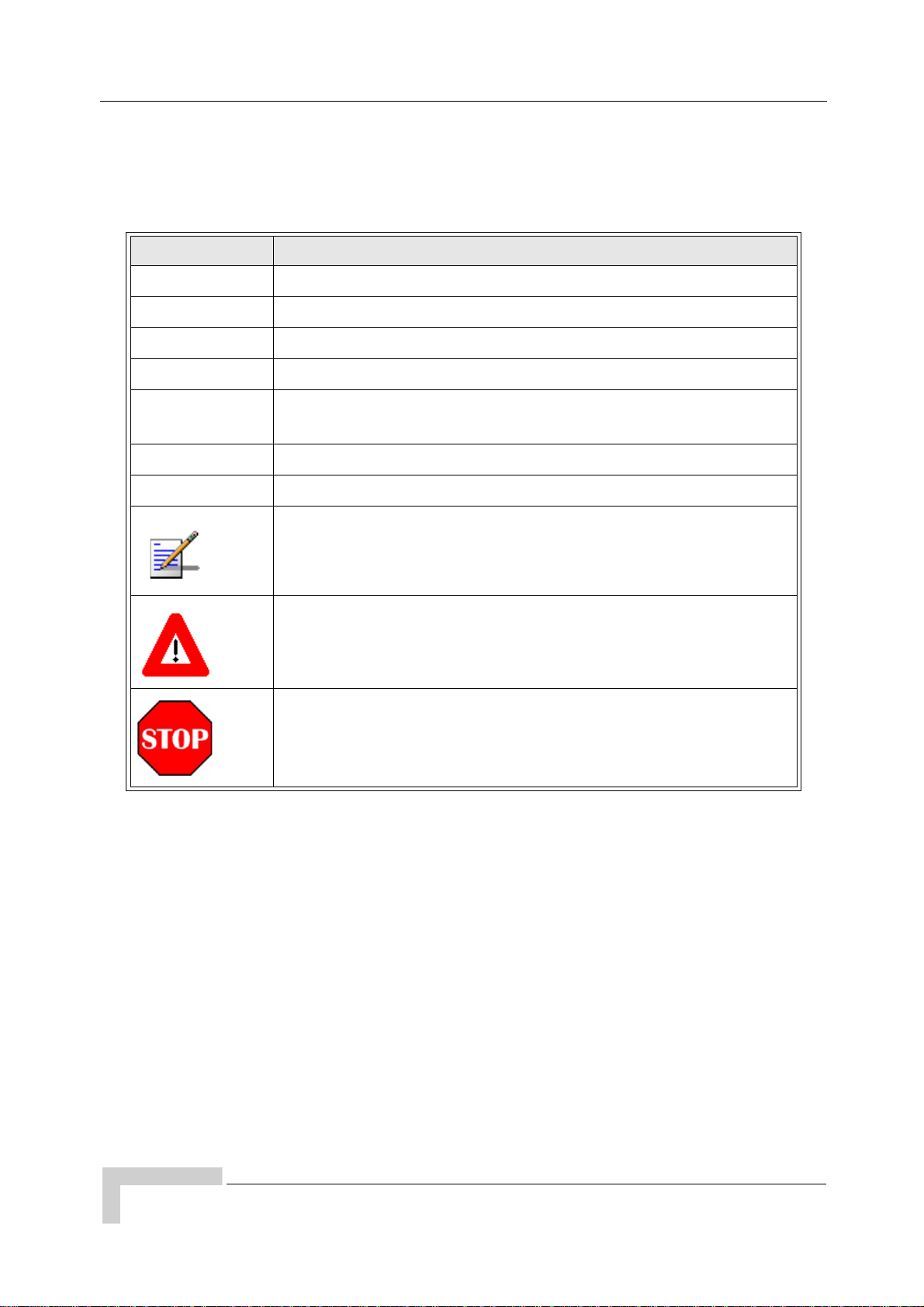
Convention Meaning
Body Text Used for regular body text
Bold Indicates a menu or button choice
Command Indicates computer generated text and prompts
User Input Indicates user input
<hostname>
<variable> In body text, indicates user-specified command line parameters
[BRACKETS] Indicates a key on the keyboard or instrument
In command syntax, indicates user-specified command line
parameters
Provides relevant additional information
Provides important warning information that may affect operation
of or maybe a potential threat to the system
Used to tell the reader to STOP what they are doing and to read
important instructions that are vital to prevent equipment or
software damage
xvi UltraWAVE Micro BTS Installation and Commissioning Guide, Version B
Page 17

1
Chapter 1 - Unpacking and Configuration Verification
In this Chapter:
“Unpacking and Inspecting” on page 2
“Electrostatic Discharge (ESD)” on page 7
“Inspecting Components and Recording Part Numbers” on page 8
“Verifying and Documenting Cards and Modules” on page 12
“Verifying Cabling” on page 15
This chapter provides instructions for opening the shipping container and
inspecting the contents. When you have completed the procedures in this chapter,
you will have confirmed that the hardware arrived undamaged and that everything
you ordered is present and configured correctly.
Page 18

Chapter 1 - Unpacking and Configuration Verification
1.1 Unpacking and Inspecting
The UltraWAVE Micro BTS is packed with great care, and all containers are
inspected prior to shipment.
Micro BTS components that are shipped separately include:
Micro subrack assembly
Power supplies
Power supply subrack assembly
The Micro subrack assembly includes RF Module(s), processor card, E1 or T1
card, TRX card(s) and the clock module.
Upon receipt of these packages, immediately inspect the outside of the shipping
containers. If there is any visible damage, insist that a representative of the
carrier is present when unpacking the contents.
Carefully inspect the system as it is unpacked. If any damage, such as dents or
broken connections, is noticeable, immediately notify the carrier as well as
Alvarion Customer Service.
Store the shipping containers for future use. If the unit has to be returned for
upgrade or service, the specially designed shipping containers assure adequate
protection for the equipment. If for some reason the containers are not reusable or
if they are misplaced, please contact Alvarion to order new containers.
1.1.1 Unpacking the Cabinet
The UltraWAVE Micro BTS is shipped in a specially designed carton. The cabinet
should remain in the packaging until shipped to its final destination. Use this
procedure to unpack your cabinet.
1 Move the cabinet to a level, well illuminated area.
2 Cut all of the strapping on the outside of the shipping container. See
Figure 1-1.
2 UltraWAVE Micro BTS Installation and Commissioning Guide, Version B
Page 19
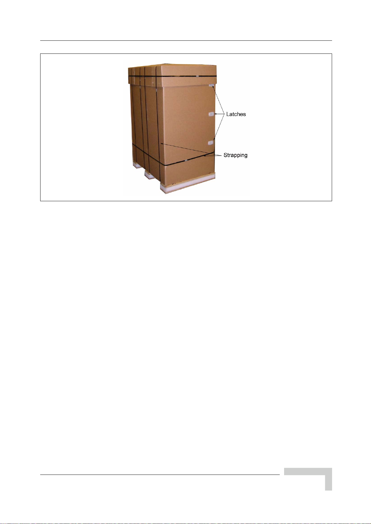
Figure 1-1: UltraWAVE Packaging
Unpacking and Inspecting
3 Remove the cardboard top and set aside.
4 Locate the plastic latches, shown in Figure 1-1. Pull on each latch to release
the cardboard side.
5 Remove the cardboard enclosing the cabinet assembly.
6 Carefully remove the two boxes from the top of the cabinet assembly. These
boxes contain the power supply units.
7 Remove the insulating material from the top and sides of the cabinet.
8 Cut the strapping which secures the cabinet to the pallet and remove the
protective plastic.
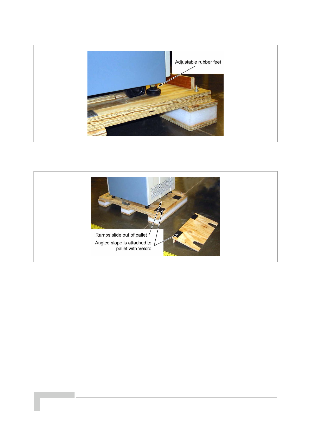
9 Using an adjustable wrench, raise the rubber feet located at each corner on
the bottom of the cabinet. See Figure 1-2.
UltraWAVE Micro BTS Installation and Commissioning Guide, Version B 3
Page 20
Chapter 1 - Unpacking and Configuration Verification
Figure 1-2: Adjustable Feet
10 Remove the angled slope and ramps from the pallet. See Figure 1-3.
Figure 1-3: Pallet Accessories
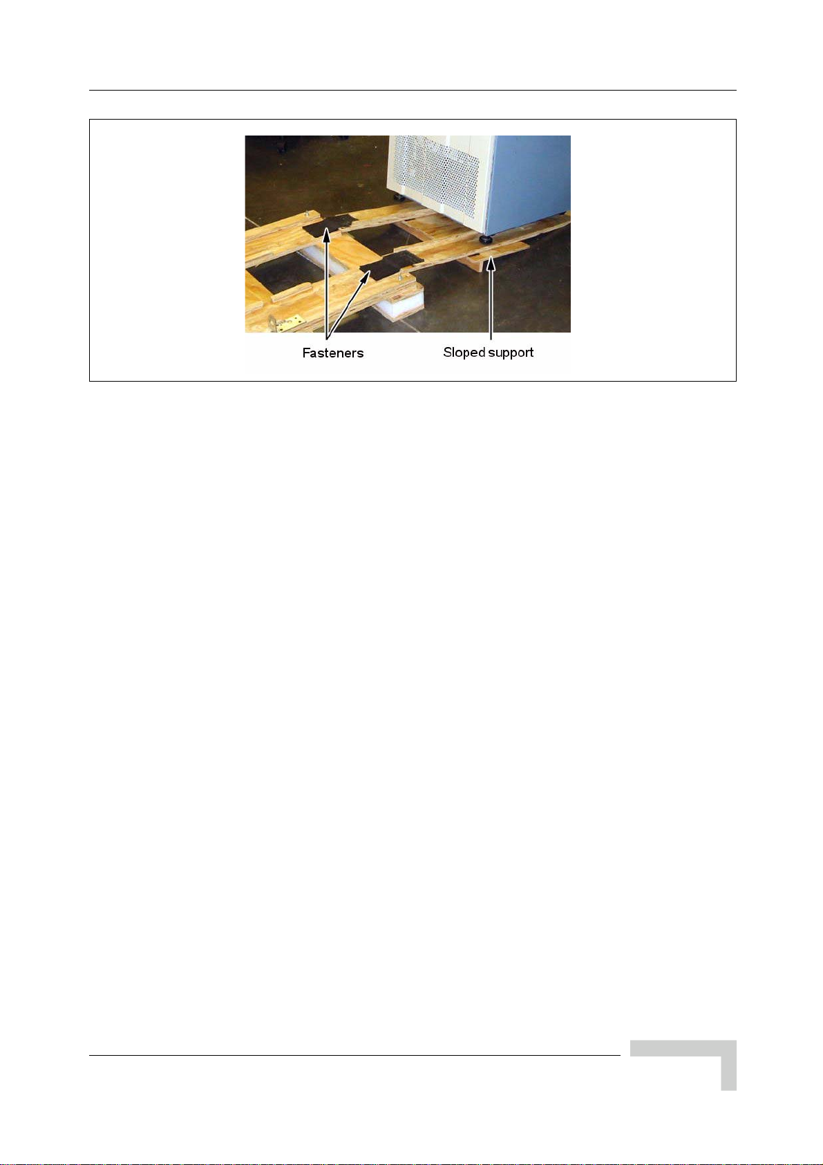
11 Attach ramps to pallet using loop and hook fasteners and slide the sloped
support underneath the ramps. See Figure 1-4.
4 UltraWAVE Micro BTS Installation and Commissioning Guide, Version B
Page 21
Unpacking and Inspecting
Figure 1-4: Pallet Ramps
12 Carefully roll the cabinet down the ramps and off of the pallet.
13 Store all packaging material in a safe, dry location.
UltraWAVE Micro BTS Installation and Commissioning Guide, Version B 5
Page 22
Chapter 1 - Unpacking and Configuration Verification
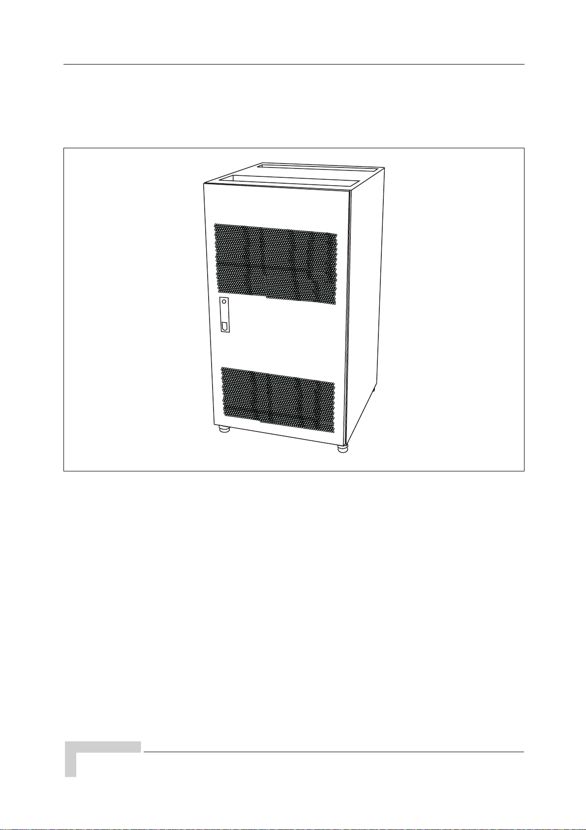
1.1.2 Opening the Cabinet Assembly
The UltraWAVE Micro BTS is shipped pre-configured in a locking cabinet
assembly as shown in Figure 1-5.
IW007302
Figure 1-5: Locking Cabinet
Doors are provided for access to the front and rear of the internal assemblies. To
open the doors:
1 Insert the key provided into the lock and turn to unlock.
2 Depress the lock mechanism to release the door latch handle.
3 Turn the door handle to unlatch and open the door.
4 Carefully remove the packaging material from inside the cabinet.
6 UltraWAVE Micro BTS Installation and Commissioning Guide, Version B
Page 23
Electrostatic Discharge (ESD)
1.1.3 Unpacking and Inspecting the Rack Assembly
The Micro BTS may be shipped in a standard 19 inch rack assembly. Carefully
inspect the system as it is unpacked. Ensure that the required cabling is
included. If you notice any damage such as dents or broken connections,
immediately notify the carrier as well as Alvarion Customer Service.
Store the shipping containers for future use. If the unit has to be returned for
upgrade or service, the specially designed shipping containers assure adequate
protection of the equipment. If for some reason the shipping containers are not
reusable or if they are misplaced, please contact Alvarion to order new containers.
1.2 Electrostatic Discharge (ESD)
Electrostatic discharge is the movement of normally motionless electrical charges
which can destroy common electrical and electronic equipment.
Alvarion recommends that you use an anti-static wrist strap when handling
boards and components.
By using an anti-static wrist-strap, static electricity is constantly dispersed, via
the snug-fitting wrist-band, down the cable and to the grounded connection at the
other end, leaving hands free to work.
Use either the provided anti-static wrist-strap or an ESD mat.
Otherwise, touch the metal chassis to drain off any static electricity before
touching the cards.
Do not wear wool or polyester clothing.
Dry air can prevent dangerous charges from harmlessly dissipating. Alvarion
recommends a relative humidity of 50-60% when working on this equipment.
Handle the cards as little as possible and only by the edges.
Before starting any of the following procedures, the Field Service
Technician needs to ensure that anti-static precautions are taken.
UltraWAVE Micro BTS Installation and Commissioning Guide, Version B 7
Page 24
Chapter 1 - Unpacking and Configuration Verification
1.3 Inspecting Components and Recording Part Numbers
The Micro BTS is shipped with all RF modules and cards installed in the Micro
subrack assembly as ordered by the customer. The Micro BTS components
include:
Micro subrack assembly
Processor card
E1 or T1 card
TRX cards
RF modules
Fan assemblies (located on the back of the chassis)
Clock module
Internal cabling
Blank panel(s)
Power supply modules and subrack assembly
Some of these components appear in Figure 1-6.
ANT
ANT
MAIN
DIV
RX1
RX1
ON LINE
RX2
RX2
RX3
RX3
RX4
RX4
TX1
DET
PA1
IN
TX2
DET
PA2
IN
01234567
PWR
FLT
RX1
RX2
ON
PWR
RX3
ONLINE
FLT
OFF
SCN
RX4
ENET
CON
IIIIIIIIIIIIIIIIIIIIIIIII
TX1
P/N XXXXXX
IIIIIIIIIIIIIIIIIIIIIIIII
DET
S/N XXXXXX
PA1
IN
TX2
DET
PA2
IN
C
RF Modules
Processor Card
E1 or T1 Trunk Card
TRX Cards
Clock Module
ANT
DIV
PWR
FLT
RX1
ON LINE
RX2
ON
RX3
OFF
RX4
A
MAIN
MAIN
DIV
PWR
FLT
RX1
RX1
ON LINE
RX2
RX2
ON
RX3
RX3
OFF
RX4
RX4
TX1
DET
PA1
IN
TX2
DET
PA2
IN
B
ANT
ANT
ANT
IIIIIIIIIIIIIIIIIIIIIIIII
P/N XXXXXX
I2C
ALARMS
ALARMS
120 OHM
12
PORT 0
12
PORT 1
IIIIIIIIIIIIIIIIIIIIIIIII
S/N XXXXXX
PWR
ON
LINE
FLT
TX
TX
TX
OUT
OUT
OUT
13 MHZ
13 MHZ
13 MHZ
CLK
CLK
CLK
RX-A
RX-A
RX-A
DET
DET
DET
IN
IN
IN
PWR
PWR
PWR
ON LINE
ON LINE
ON LINE
FLT
FLT
FLT
RX-B
RX-B
RX-B
TX
TX
TX
OUT
OUT
OUT
13 MHZ
13 MHZ
13 MHZ
CLK
CLK
CLK
RX-A
RX-A
RX-A
DET
DET
DET
IN
IN
IN
PWR
PWR
PWR
ON LINE
ON LINE
ON LINE
FLT
FLT
FLT
RX-B
RX-B
RX-B
IW132601
Figure 1-6: UltraWAVE Micro Subrack Assembly
8 UltraWAVE Micro BTS Installation and Commissioning Guide, Version B
Page 25
Inspecting Components and Recording Part Numbers
1.3.1 Identifying the System Configuration
The UltraWAVE Micro BTS is available in a number of different configurations.
Micro BTS available configurations are listed in Table 1-1. Use this section to
verify the configuration of your UltraWAVE Micro BTS.
Locate the main configuration label on the exterior of your shipping container or
on the back of the Micro subrack assembly.
MODEL: AKAD
MODEL NUMBER: AKADO21902512482B
INPUT POWER:
MFG DATE: JUL 11, 2006
-48VDC, 10A
SERIAL:
REVISION:
P/N:
00xxxxx
612872
B
IW192603
Figure 1-7: Configuration Label
The main configuration label includes the following details:
Serial number (00xxxxxx).
P/N (xxxxxx).
Revision letter (X).
Model (example: AKAD) - denotes the type of Alvarion system, in this case an
UltraWAVE Micro BTS.
Factory configuration number.
Input Power (example: -48VDC, 10A).
Manufacturing date (month, date, year).
UltraWAVE Micro BTS Installation and Commissioning Guide, Version B 9
Page 26
Chapter 1 - Unpacking and Configuration Verification
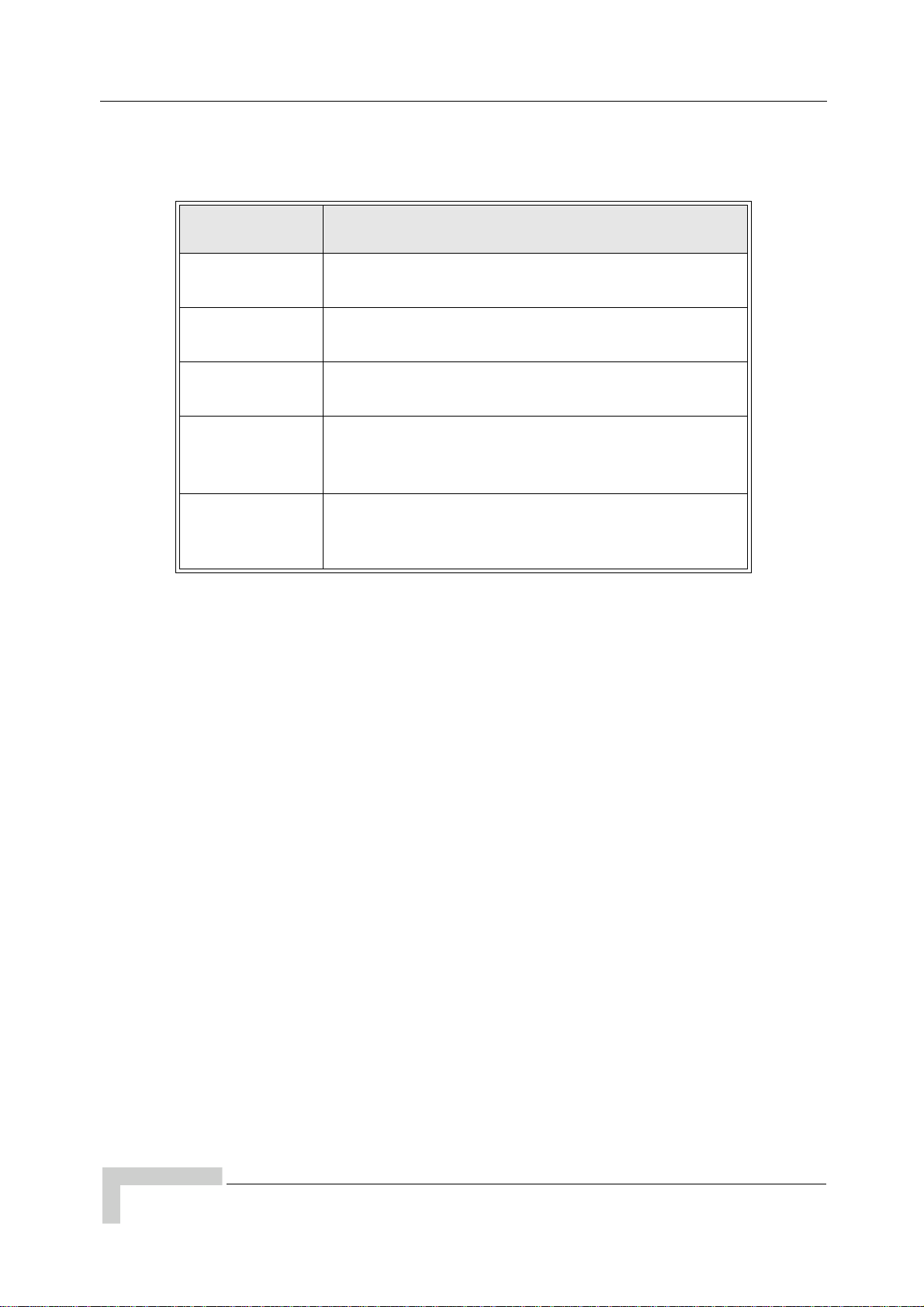
Table 1-1 lists Micro BTS configuration types and details.
Table 1-1: Configuration Type and Details
Configuration
Type
01
02
03
Configuration Details
Omni single TRX (01); 15 Watt, 25 Watt, 40 Watt or
50 Watt, two antenna configuration
Omni two TRX (02); 15 Watt, 25 Watt, 40 Watt or
50 Watt, two antenna configuration
Omni three TRX (03); 15 Watt or 25 Watt, two
antenna configuration
Three sector, one TRX per sector (S111); 15 Watt,
S111
25 Watt, 40 Watt or 50 Watt, six antenna
configuration
Three sector, two TRXs in one sector and one TRX in
S222
the other two sectors (S222), 15 Watt, 25 Watt,
40 Watt or 50 Watt, six antenna configuration
Record your model and configuration details in Checklist 2 - Installation
Checklist.
10 UltraWAVE Micro BTS Installation and Commissioning Guide, Version B
Page 27
Inspecting Components and Recording Part Numbers
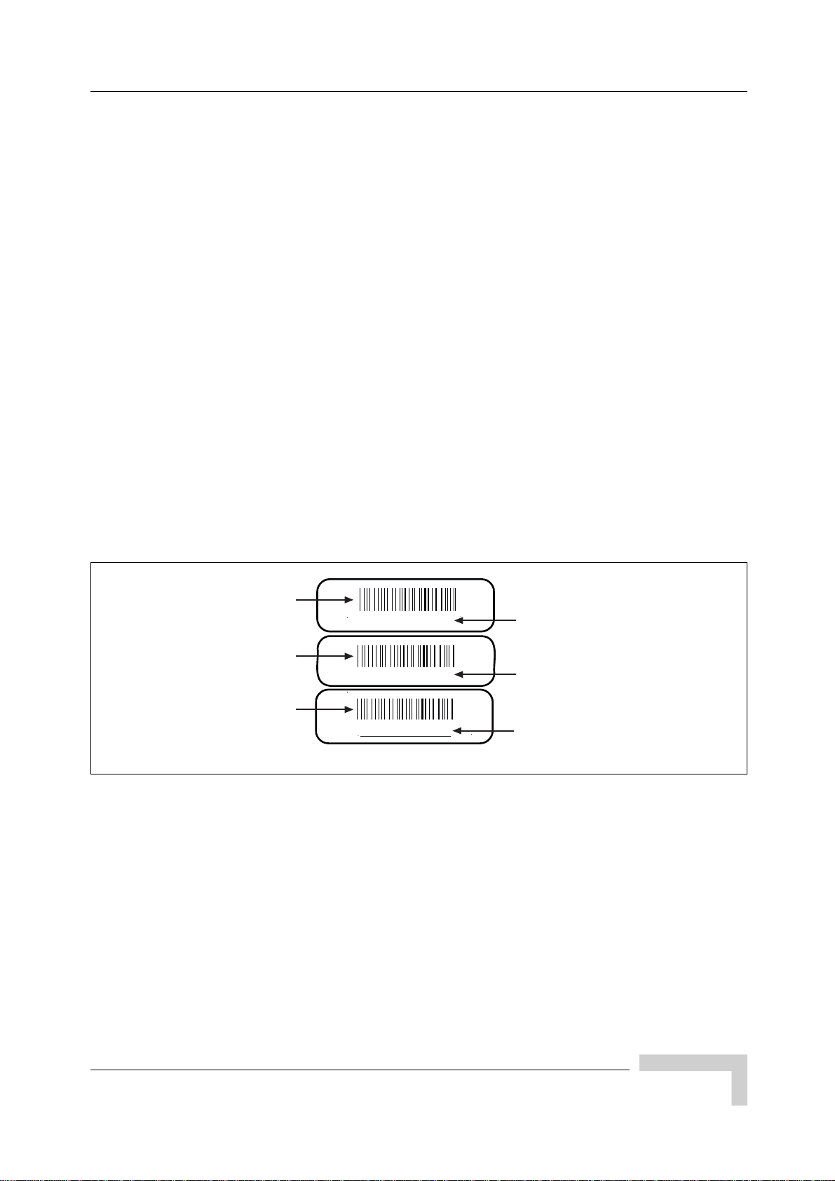
1.3.2 Verifying System Labels
This procedure requires you to record each components’ part number, revision
number and serial number in Checklist 2 - Installation Checklist. The factory
places up to three configuration labels on the front of each Micro BTS card,
module and chassis to help identify the system’s configuration. These labels
identify the following:
Part number -- Part number identifies the type of component. All identical
components have the same part number. Part numbers use the format:
P/N NNNNNN
Revision or dash number -- Revision numbers record minor changes in design.
Revision numbers use the format:
-NNN
Serial number -- Each individual component has its own unique serial
number. Serial numbers use the format:
S/N NNNNNNNN
An example of the configuration labels appears in Figure 1-8.
Barcode identifier of
the part number
Barcode identifier of
the rev number
Barcode identifier of
the serial number
P/N 340127
-200
S/N 00719500
Part number
Dash or revision number
Serial number
Figure 1-8: Sample Configuration Labels
IE168405
UltraWAVE Micro BTS Installation and Commissioning Guide, Version B 11
Page 28

Chapter 1 - Unpacking and Configuration Verification
1.4 Verifying and Documenting Cards and Modules
The cabinet contains two subrack assemblies.
The Micro contains:
RF modules responsible for RF power amplification, duplexing and
combining when required
Processor Card, E1 or T1 trunk card, TRX cards, and clock module
The power supply consists of up to two power supply modules and a third slot
covered with a blank panel.
1.4.1 Required Equipment
To verify and record your system configuration, you need:
A copy of the Shipping Checklist. It is one of the papers inside the shipping
container.
A copy of Checklist 2 - Installation Checklist.
1.4.2 Micro Subrack Assembly
The Micro subrack assembly provides three RF slots, starting on the left with slot
A. Depending on your Micro BTS configuration, up to three slots will be required
for RF modules. These modules are shipped pre-installed and cabled from the
factory.
1 Locate the configuration part and serial numbers on your RF modules.
Figure 1-8 illustrates a sample of these labels.
2 Write down the part number, revision number and serial number in Checklist
2 - Installation Checklist.
12 UltraWAVE Micro BTS Installation and Commissioning Guide, Version B
Page 29
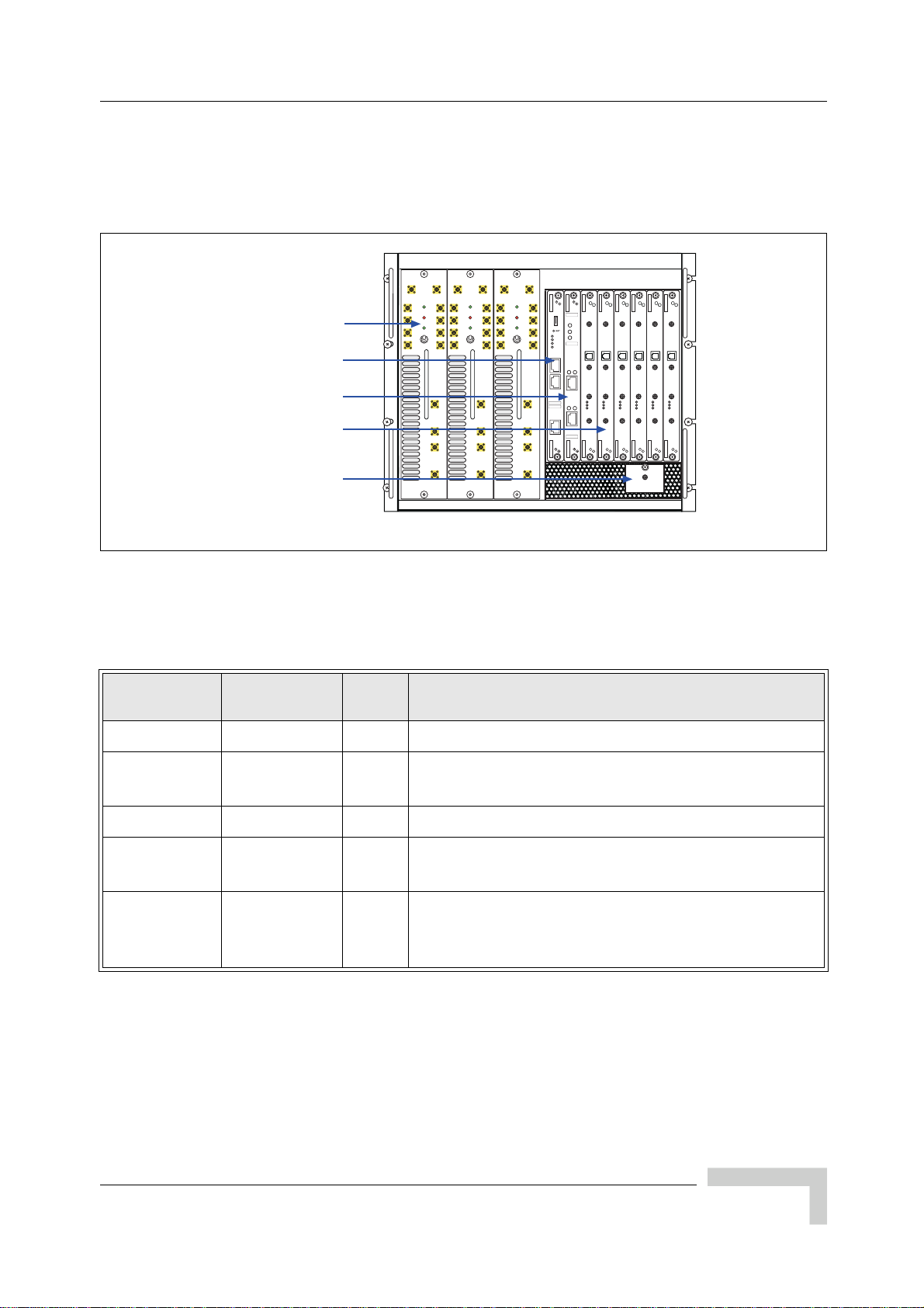
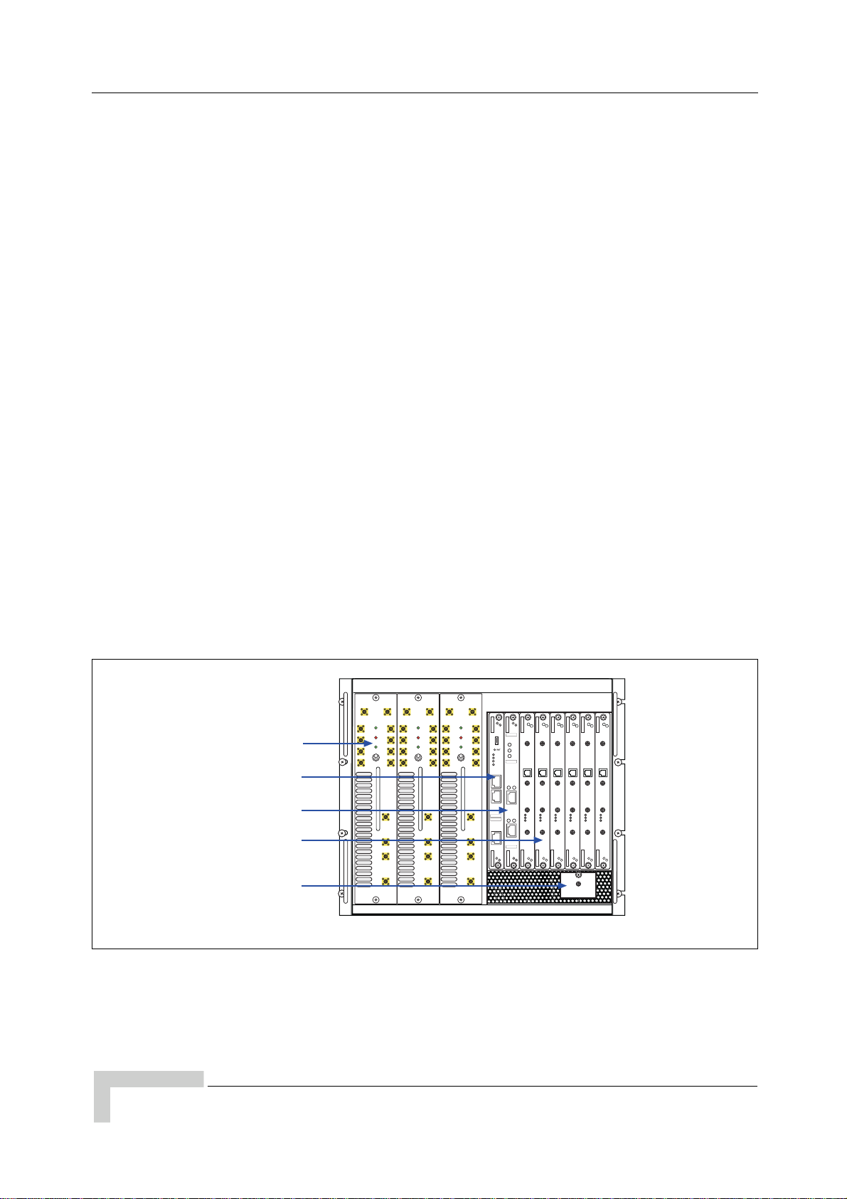
1.4.3 Slot Assignments
Beside the RF slots, the Micro BTS chassis layout provides eight standard slots,
starting on the left with slot 0. See Figure 1-9.
Verifying and Documenting Cards and Modules
Processor Card
E1 or T1 Trunk Card
Clock Module
Table 1-2 shows the Micro BTS slot assignments in the Micro subrack assembly.
Card Slots
RF Modules
TRX Cards
Figure 1-9: Micro BTS Chassis Layout
Table 1-2: Micro BTS Slot Assignments
Width
(slots)
ANT
ANT
MAIN
DIV
PWR
FLT
RX1
RX1
ON LINE
RX2
RX2
ON
RX3
RX3
OFF
RX4
RX4
TX1
DET
PA1
IN
TX2
DET
PA2
IN
A
Function
ANT
ANT
MAIN
DIV
PWR
FLT
RX1
ON LINE
RX2
ON
RX3
OFF
RX4
B
ANT
ANT
MAIN
DIV
RX1
RX1
ON LINE
RX2
RX2
RX3
RX3
RX4
RX4
TX1
DET
PA1
IN
TX2
DET
PA2
IN
01234567
PWR
FLT
ON
OFF
IIIIIIIIIIIIIIIIIIIIIIIII
RX1
P/N XXXXXX
I2C
PWR
RX2
ON
LINE
PWR
FLT
RX3
ONLINE
FLT
120 OHM
SCN
RX4
ENET
ALARMS
12
CON
PORT 0
ALARMS
IIIIIIIIIIIIIIIIIIIIIIIII
TX1
P/N XXXXXX
12
IIIIIIIIIIIIIIIIIIIIIIIII
DET
S/N XXXXXX
PORT 1
PA1
IN
IIIIIIIIIIIIIIIIIIIIIIIII
S/N XXXXXX
TX2
DET
PA2
IN
TX
OUT
OUT
OUT
13 MHZ
13 MHZ
13 MHZ
CLK
CLK
CLK
RX-A
RX-A
RX-A
DET
DET
DET
IN
IN
IN
PWR
PWR
PWR
ON LINE
ON LINE
ON LINE
FLT
FLT
FLT
RX-B
RX-B
RX-B
OUT
OUT
OUT
13 MHZ
13 MHZ
13 MHZ
CLK
CLK
CLK
RX-A
RX-A
RX-A
DET
DET
DET
IN
IN
IN
PWR
PWR
PWR
ON LINE
ON LINE
ON LINE
FLT
FLT
FLT
RX-B
RX-B
RX-B
TX
TX
TX
TX
TX
C
IW132601
RF Modules A, B, C 1 RF power amplification, duplexing and combining.
Processor
card
0 1 ICP processor card.
E1 or T1 1 1 Each E1 or T1 card provides 2 E1 or T1 lines.
TRX
Clock
Module
2, 3, 4, 5, 6,
7
1 Each TRX manages 8 radio channels.
NA NA
The clock module is located directly underneath the
TRX cards, and provides synchronization for the
Air-interface and E1/ T1 modules.
The minimum configuration consists of a processor card in slot 0, one E1 or T1
card in slot 1, one TRX in slot 7, a clock module and an RF module in slot C. Any
unused slots must be covered by a blank panel.
UltraWAVE Micro BTS Installation and Commissioning Guide, Version B 13
Page 30

Chapter 1 - Unpacking and Configuration Verification
1.4.4 Verification Procedure
Use the following procedure to identify and record your system components.
Compare components against those listed in the shipping checklist. See
Figure 1-9 for Micro BTS chassis component locations.
1 Verify that the subrack assembly has four fan assemblies on the power
amplifier side on the rear of the chassis and two fans on the VME bus cards
side on the rear of the chassis. Verify that the fans are securely fastened to the
chassis.
2 Verify that the Micro BTS rack assembly contains an one or more RF modules
in slots A, B and/or C of the Micro rack assembly. Write down the part
number, revision number and serial number of each RF module in Checklist 2
- Installation Checklist.
3 Verify that the chassis contains an ICP processor card in slot 0 of the Micro
subrack assembly. Write down the processor card part number, revision
number and serial number in Checklist 2 - Installation Checklist.
4 Slot 1 of the Micro subrack assembly should contain an E1 or T1 card. From
the shipping checklist, write down the part number, revision number and
serial number of the E1 or T1 card in Checklist 2 - Installation Checklist.
5 Slots 2 to 7 should contain one or more TRXs. Verify how many are required
from the shipping checklist, then verify that they are all there. Write down the
part number, revision number and serial number of each TRX card in Check-
list 2 - Installation Checklist.
6 Check the shipping checklist and verify that the power supply subrack
assembly has one or two power supply modules and power supply fan assemblies. One or two power supply modules are required depending on your
configuration. Verify that a third slot and any other open slot is covered with a
blank panel.
For each power supply module, write down the part number, revision number
and serial number in Checklist 2 - Installation Checklist.
7 Verify that all empty slots are covered by blank panels. These are necessary for
cooling, and to meet RF emission standards.
14 UltraWAVE Micro BTS Installation and Commissioning Guide, Version B
Page 31

1.5 Verifying Cabling
In this section, you inspect the internal cabling and verify that it is configured
correctly.
1.5.1 Verifying Internal Cabling
When the Micro BTS assembly and the power supply rack assembly are mounted
in the rack enclosure, all E1 or T1 interfaces are routed directly to the trunk cards
through a dust protector on the rack. The interface access area is mounted in the
rear recessed area of the rack enclosure. The internal cabling also connects the
power supply modules to the Micro subrack assembly and provides a plug on the
exterior of the cabinet for connection to the power source.
The internal cabling of the Micro BTS is included for the rack enclosure
configuration only, and is completed by the manufacturer. Due to its complexity,
it is not recommended for you to move or disconnect internal cabling.
Verifying Cabling
1.5.2 Verifying Enclosure Cabling
When the Micro subrack assembly and power supply modules are mounted in the
rack enclosure, it is necessary to verify that the following cables are connected:
Alarm cable and I
Power supply cables
Ensure that:
The alarm cable is connected to the power supply subrack assembly and the
Micro assembly.
A USB style cable is connected from the I
the front of the ICP processor card.
The power supply subrack assembly power cables are connected to the Micro
subrack assembly. See Figure 1-10, Power Supply Cable 1 and Power Supply
Cable 2.
The external power supply cable (Input Power Supply) is connected to the
power supply subrack assembly.
2
C interface cable
2
C interface to the I2C connector on
UltraWAVE Micro BTS Installation and Commissioning Guide, Version B 15
Page 32

Chapter 1 - Unpacking and Configuration Verification
Figure 1-10: Micro Subrack and Power Supply Assembly Rear View
Figure 1-10 shows the location of the following components from the rear view of
the Micro subrack assembly and power supply assembly:
Fan Assemblies
External Alarm Interface
Mounting Brackets
Power Supply 1 cable for slots A through C
Power Supply 2 cable for slots 0 through 7
Processor Card Interface
The ICP processor card uses an I
USB style cable between the processor card interface connector and the I
2
C interface and connects physically with a
2
C
connector on the front of the ICP processor card.
Input Power Supply cable connection
Please proceed to Chapter 2 - Installation to install your Micro BTS.
16 UltraWAVE Micro BTS Installation and Commissioning Guide, Version B
Page 33

Chapter 2 - Installation
In this Chapter:
“Analyzing Site Requirements” on page 18
“Mounting the Micro BTS Chassis” on page 22
“Configuring the E1 or T1 Trunk Card” on page 31
“Connecting Ground Cables” on page 36
“Connecting Power Supplies” on page 38
2
“Connecting E1 or T1 Trunk Cables” on page 47
“Connecting Antennas” on page 52
“Connecting External Alarms” on page 60
“Making a Serial Connection to the Processor Card” on page 64
“Network Connections” on page 65
“Post Installation Cabling and Checks” on page 66
This chapter provides instructions for installing and configuring the Micro BTS
hardware.
Page 34

Chapter 2 - Installation
2.1 Analyzing Site Requirements
Before a site is chosen or equipment installed, a site survey must be carried out.
The site survey checklist assists the surveyor with the inspection and the
collection of site specific information such as environmental conditions, electrical
requirements, and mechanical requirements.
The site survey checklist must be completed before installation begins. The
necessary steps for site readiness are listed in Checklist 1 - Site Readiness
Checklist. The GSM Network Implementation Manual
site requirements.
The site readiness checklist assists the field service engineer or operator to ensure
that the site is ready for equipment installation. It includes information about:
Environmental conditions
Electrical requirements
provides additional detailed
Chassis requirements
The site readiness checklist is located in Checklist 1 - Site Readiness Checklist. It
must be completed as part of the installation process.
2.1.1 Environmental Conditions
The Micro BTS is designed to operate indoors only. To facilitate long-term
operability and durability of the Micro BTS, observe specific environmental
constraints.
Before installing the Micro BTS, ensure that the operating environment maintains
a temperature and humidity within the ranges shown in Table 2-1.
Make sure the ambient temperature around the unit (which may
be higher than the room temperature) is within the specified limit
for the unit.
Table 2-1: Micro BTS Operating Environment
Scale
Maximum 90% 55 degrees 131 degrees
Minimum 10% -5 degrees 23 degrees
18 UltraWAVE Micro BTS Installation and Commissioning Guide, Version B
Humidity
(non-condensing)
Temperature
(Celsius)
Temperature
(Fahrenheit)
Page 35

2.1.2 Electrical Requirements
The Micro BTS is specified to operate on either AC or DC power. Requirements for
the Micro BTS are dependent on the number of TRX cards supported.
Power Options
Main power supply options for the Micro BTS are:
110 VAC to 220 VAC auto-ranging, 30 A, 50-60 Hz
-40 VDC to -60 VDC (-48 VDC nominal), 40 A
Table 2-2 shows the estimated power requirements for the different TRX
configurations for the Micro BTS.
Table 2-2: Estimated Power Requirements for TRX Configurations
Analyzing Site Requirements
Product
Configuration
One TRX 261 Watts 350 Watts 345 Watts
Two TRXs 531 Watts 700 Watts 690 Watts
Three TRXs 801 Watts 1050 Watts 1035 Watts
Four TRXs 1071 Watts 1400 Watts 1380 Watts
Six TRXs 1611 Watts 2100 Watts 2070 Watts
Table 2-3 shows Micro BTS Power Specifications.
Power Requirements Specification
Micro BTS voltage range: 110 VAC 90 to 264 VAC
Micro BTS power protection: 110 VAC Dedicated 30 amp circuit breaker
Micro BTS voltage range: 220 VAC 90 to 264 VAC
Micro BTS power protection: 220 VAC Dedicated 15 Amp circuit breaker
Micro BTS DC voltage range: -48 VDC -40 to -60 VDC
-48 VDC 110 VAC 220 VAC
Table 2-3: Micro BTS Power Specifications
Micro BTS DC power protection: -48 VDC Dedicated 40 Amp fuse/circuit breaker
UltraWAVE Micro BTS Installation and Commissioning Guide, Version B 19
Page 36

Chapter 2 - Installation
2.1.3 Chassis Requirements
Before installing the Micro BTS, ensure that adequate clearance space is allowed
around the unit. Enough clearance should be provided from the front and back of
the cabinet to fully open the doors. This requires at least 24 inches (61 cm) from
the front and rear doors. The minimum clearance required on either side of the
cabinet is 4.5 inches (11.4 cm) and the minimum clearance required below the
cabinet is 1.8 inches (4.59 cm). The mounting site should also have ample
clearance for the trunk and antenna cables to be attached to the connectors at the
top of the cabinet.
The Micro BTS should be installed away from salt spray and in an area where
there are minimal vibrations.
Table 2-4 lists the dimensions of the Micro BTS chassis.
Table 2-4: Micro BTS Chassis Dimensions
Scale Height Width Depth
Metric 39.93 cm 48.26 cm 43.82 cm
Imperial 15.72 inches 19.0 inches 17.25 inches
Table 2-5 lists the weight and dimensions of the power supply rack.
Table 2-5: Power Supply Rack Weight and Dimensions
Weight
Scale
Metric 23.8 kg
Imperial 52.35 lbs
(Maximum
Configuration)
Table 2-6 and Figure 2-1 provide the dimensions of the BTS cabinet. For detailed
cabinet dimensions, refer to Section 2.2.
Table 2-6: Micro BTS Cabinet Weight and Dimensions
Height Width Depth
12.5 cm (AC)
48.26 cm 51.44 cm
13 cm (DC)
5 inches (AC)
19.0 inches 20.25 inches
5.2 inches (DC)
Scale
Metric 166 kg 105.1 cm 56.0 cm 64.77 cm
Imperial 365 lbs 41.38 inches 22.05 inches 25.5 inches
20 UltraWAVE Micro BTS Installation and Commissioning Guide, Version B
Weight
(Maximum Configuration)
Height Width Depth
Page 37

Analyzing Site Requirements
WHEEL_SV
WHEEL_SV
WHEEL_FV WHEEL_FV
DOOR_
FV
CAB_F
V
RUBFE
ET
RUBFE
ET
CAB_S
V
DOOR_SVSV
DOOR_SVSV
RUBFE
ET
RUBFE
ET
When fully loaded, two people are required to lift the chassis. (The
two man lift requirement applies to loads of over 80 kg.)
41.375 in. [105.09 cm]
DOOR_
FV
CAB_F
V
WHEEL_FV
RUBFE
ET
19.925 in. [50.61 cm]
The steps for site readiness are listed in Checklist 1 - Site
Readiness Checklist.
DOOR_
CAB_S
V
RUBFE
ET
RUBFE
ET
20.925 in. [53.15 cm]
M10 Tap Holes
(each corner)
Figure 2-1: Cabinet Footing Dimensions
DOOR_
RUBFE
ET
M12-1.75
(each corner)
1.808 in
[4.59 cm]
IW008301
UltraWAVE Micro BTS Installation and Commissioning Guide, Version B 21
Page 38

Chapter 2 - Installation
2.2 Mounting the Micro BTS Chassis
The Micro BTS is offered in two different configurations:
19 inch (48.26 cm) rack assembly
Cabinet enclosure assembly
Upon ordering the Micro BTS, the desired type of mounting must be specified, as
a separate mounting kit is supplied for each option.
This section describes all the necessary steps for installing a Micro BTS. It is
divided into two subsections. These two sections are:
Rack installation. Section 2.2.1
Enclosure mounting. Section 2.2.2
Each of these sections contain complete instructions on how to install the Micro
BTS in different configurations. Please refer to the appropriate section.
Ensure that:
• The ambient temperature around the unit (which may be higher
than the room temperature) is within the limit specified for the
unit.
• There is sufficient airflow around the unit.
• The electrical circuits are not overloaded - consider the name
plate rating of all the connected equipment and make sure you
have over current protection.
• The equipment is properly grounded.
• No objects are placed on top of the unit.
22 UltraWAVE Micro BTS Installation and Commissioning Guide, Version B
Page 39

2.2.1 Rack Installation
The Micro BTS may be ordered with or without a standard EIA 19 inch rack
enclosure as defined in EIA standard RS-310-D Racks, Panels and Associated
Equipment. If you ordered the rack enclosure, the Micro subrack assembly and
the power supply subrack assembly will be mounted inside the rack enclosure
with cable access to the outside of the enclosure.
The minimum clearance required above and below the chassis is 1.0" (2.54 cm)
and the minimum clearance required behind the chassis is 1.0" (2.54 cm). The
mounting site should also have ample clearance for the trunk cables to be
attached to the front panel connectors.
Required Materials
12 standard customer-provided rack mount screws
Optional Materials
One standard 19" (48.26 cm) rack mount shelf assembly
Mounting the Micro BTS Chassis
Required Tools
Rack mount screwdriver
Rack Mount Advisory
To prevent bodily injury when mounting or servicing this unit in a rack, you must
take special precautions to ensure that the system remains stable. The following
guidelines are provided to ensure your safety:
This unit should be mounted at the bottom of the rack if it is the only unit in
the rack.
When mounting this unit in a partially filled rack, load the rack from the
bottom to the top with the heaviest component at the bottom of the rack.
If the rack is provided with stabilizing devices, install the stabilizers before
mounting or servicing the unit in the rack.
Attention: Pour éviter toute blessure corporelle pendant les opérations de montage
ou de réparation de cette unité en casier, il convient de prendre des précautions
spéciales afin de maintenir la stabilité du système. Les directives ci-dessous sont
destinées à assurer la protection du personnel:
Si cette unité constitue la seule unité montée en casier, elle doit être placée
dans le bas.
Si cette unité est montée dans un casier partiellement rempli, charger le casier
de bas en haut en plaçant l'élément le plus lourd dans le bas.
UltraWAVE Micro BTS Installation and Commissioning Guide, Version B 23
Page 40

Chapter 2 - Installation
Si le casier est équipé de dispositifs stabilisateurs, installer les stabilisateurs
avant de monter ou de réparer l'unité en casier.
Warnung: Zur Vermeidung von Körperverletzung beim Anbringen oder Warten
dieser Einheit in einem Gestell müssen Sie besondere Vorkehrungen treffen, um
sicherzustellen, daß das System stabil bleibt. Die folgenden Richtlinien sollen zur
Gewährleistung Ihrer Sicherheit dienen:
Wenn diese Einheit die einzige im Gestell ist, sollte sie unten im Gestell ange-
bracht werden.
Bei Anbringung dieser Einheit in einem zum Teil gefüllten Gestell ist das
Gestell von unten nach oben zu laden, wobei das schwerste Bauteil unten im
Gestell anzubringen ist.
Wird das Gestell mit Stabilisierungszubehör geliefert, sind zuerst die Stabilisa-
toren zu installieren, bevor Sie die Einheit im Gestell anbringen oder sie
warten.
Installation Instructions
1 Allocate nine rack units of space in your 19" rack for the Micro subrack
assembly and three rack units of space for the power supply subrack
assembly.
2 The rack mount brackets have cutouts to accommodate the rack screws.
Using two people, carefully align the Micro subrack assembly with the rack
holes.
3 Mount the Micro BTS subrack assembly in the rack using customer-provided
screws.
4 Using the same procedure, align and mount the power supply subrack
assembly below the Micro BTS subrack assembly, as shown in Figure 2-2.
Optionally, you can mount a rack mount shelf assembly and use
the shelf to support the two rack assemblies. Both assemblies
must also be secured to the rack unit.
24 UltraWAVE Micro BTS Installation and Commissioning Guide, Version B
Page 41

Mounting the Micro BTS Chassis
.
ANT
ANT
MAIN
DIV
PWR
FLT
RX1
RX1
ON LINE
RX2
RX2
ON
RX3
RX3
OFF
RX4
RX4
A
ANT
ANT
MAIN
DIV
PWR
FLT
RX1
RX1
ON LINE
RX2
RX2
ON
RX3
RX3
OFF
RX4
RX4
TX1
DET
PA1
IN
TX2
DET
PA2
IN
B
INPUT
OUTPUT
FAULT
ON
OFF
UNLOCK
ANT
ANT
MAIN
DIV
RX1
ON LINE
RX2
RX3
RX4
TX1
DET
PA1
IN
TX2
DET
PA2
IN
01234567
PWR
FLT
ON
OFF
IIIIIIIIIIIIIIIIIIIIIIIII
RX1
P/N XXXXXX
I2C
RX2
RX3
RX4
PWR
TX
ON
OUT
LINE
PWR
FLT
ONLINE
FLT
120 OHM
13 MHZ
SCN
CLK
ENET
ALARMS
12
RX-A
DET
CON
IN
PORT 0
ALARMS
PWR
IIIIIIIIIIIIIIIIIIIIIIIII
TX1
P/N XXXXXX
12
ON LINE
IIIIIIIIIIIIIIIIIIIIIIIII
DET
S/N XXXXXX
FLT
RX-B
PORT 1
PA1
IN
IIIIIIIIIIIIIIIIIIIIIIIII
S/N XXXXXX
TX2
DET
PA2
IN
TX
OUT
OUT
13 MHZ
13 MHZ
CLK
CLK
RX-A
RX-A
DET
DET
IN
IN
PWR
PWR
ON LINE
ON LINE
FLT
FLT
RX-B
RX-B
OUT
OUT
OUT
13 MHZ
13 MHZ
13 MHZ
CLK
CLK
CLK
RX-A
RX-A
RX-A
DET
DET
DET
IN
IN
IN
PWR
PWR
PWR
ON LINE
ON LINE
ON LINE
FLT
FLT
FLT
RX-B
RX-B
RX-B
TX
TX
TX
TX
C
INPUT
OUTPUT
FAULT
ON
OFF
UNLOCK
Figure 2-2: Attaching the Subrack Assemblies
Rack Screws
x8
Rack Screws
x4
IE027601
5 Connect the alarm cable between the power supply subrack assembly and the
Micro subrack assembly. See Figure 2-3. Secure the cable by tightening the
phillips screws.
6 Connect Power Supply Cable 1 and Power Supply Cable 2 between the power
supply subrack assembly and the Micro BTS subrack assembly. See
Figure 2-3. The connector to the Micro subrack assembly will snap into place,
while you must tighten the round quick disconnect connector by twisting the
connector housing.
Refer to Section 1.5 for more information on cabling and on verifying that cables
are connected correctly.
UltraWAVE Micro BTS Installation and Commissioning Guide, Version B 25
Page 42

Chapter 2 - Installation
USB Cable to
Processor Card
External Alarm
Interface
Power Supply
Cable 2
Power Supply
Cable 1
EP1 EP2 EP3 EP4 EP5 EP6 EP7 EP8 EP9 EP10 EP11 EP12 EP13 EP14 EP15 EP16
EP17 EP18 EP19 EP20
Figure 2-3: Power Cabling and Alarm Cabling
7 You have completed the hardware installation. Proceed to Section 2.3 to
continue the Micro BTS configuration.
Alarm Cable
Input Power
Supply
IW144601
26 UltraWAVE Micro BTS Installation and Commissioning Guide, Version B
Page 43

2.2.2 Enclosure Mounting
The Micro BTS chassis should be mounted on a concrete pad of sufficient density
to support the weight of the cabinet assembly. Alignment pins may be installed in
the concrete pad at the locations provided in Figure 2-4. The alignment pins
should be 0.5 inches (1.27 cm) in diameter and protrude from 4.1 inches to
4.4 inches (10.41 cm to 11.18 cm) from the concrete pad.
22.63 in. [57.48 cm]
10.00 in.
[25.40 cm]
14.567 in.
[37.00] cm
Mounting the Micro BTS Chassis
Rubber feet
Mounting hole
M16-2 x4 places
Alignment holes
0.551 in. [1.40 cm]
20.898 in. [53.08 cm]
IW021301
Figure 2-4: Cabinet Footprint
Enough clearance should be provided from the front and back of the cabinet to
fully open the doors. This requires at least 24 inches (61 cm) from the front and
rear doors. The minimum clearance required on either side of the cabinet is
4.5 inches (11.4 cm) and the minimum clearance required below the cabinet is
1.8 inches (4.59 cm). The mounting site should also have ample clearance for the
trunk and antenna cables to be attached to the connectors at the top of the
cabinet.
The required footprint for your cabinet installation must be at least 73.5 inches
(186.7 cm) by 31.5 inches (80 cm). Be sure there is sufficient airflow around the
unit.
UltraWAVE Micro BTS Installation and Commissioning Guide, Version B 27
Page 44

Chapter 2 - Installation
20.547 in.
[52.19 cm]
Tapped hole
M10-1.5 x4 places
22.280 in.
[56.59 cm]
0.868 in.
[2.21] cm
40.904 in.
[103.90 cm]
19.780 in.
[50.24 cm]
Cabinet (side)Cabinet (top)
Tapped hole
M10-1.5
x4 places
IW021302
Figure 2-5: Cabinet Dimensions
The cabinet is mounted on casters and may be carefully moved from the
unpacking site to its final mounting location. The cabinet has four rubber feet
which will raise the cabinet off of the casters. The dimensions for the engagement
height of the rubber feet is shown in Figure 2-1. If you have alignment pins
mounted in your concrete pad, use the procedure in this section.
If you do not have the alignment pins, Figure 2-5 illustrates the location of eight
M10 tap holes which may be used for additional mounting studs, eye hooks or
angle brackets for securing the Micro BTS cabinet in its final location.
• Make sure the ambient temperature around the unit (which
may be higher than the room temperature) is within the
specified limit.
• Make sure there is sufficient airflow around the unit.
• Make sure electrical circuits are not overloaded - consider the
nameplate rating of all the connected equipment, and make
sure you have over current protection.
• Make sure the equipment is properly grounded.
• Make sure no objects are placed on the top of the unit.
28 UltraWAVE Micro BTS Installation and Commissioning Guide, Version B
Page 45

Required Materials
Angle brackets
Four M10 machine screws and washers
Required Tools
15 mm open end wrench
Installation Instructions
1 Move the cabinet into its final location. If using alignment pins to prevent
movement, move the cabinet into position over the pins.
2 Lower each of the rubber feet until each reaches the concrete pad.
3 Using the 15 mm open end wrench, lower each foot until the casters are raised
from the concrete floor, approximately 0.25 inches (0.65 cm).
4 Remove the casters from the bottom of the cabinet.
Mounting the Micro BTS Chassis
5 Lower the cabinet to within 4.1 inches to 4.4 inches (10.41 cm to 11.18 cm) of
the concrete pad. If you are using alignment pins, lower the cabinet until the
pins enter the alignment holes no more than 0.25 inches (0.6 cm). Do not
lower the cabinet too far over alignment pins as they may puncture internal
components.
6 Secure locking nuts on foot studs.
7 Secure the cabinet using customer-provided 10 mm studs.
You may use the additional M10 tap holes to secure the cabinet
as site-specific conditions allow.
Rack Mount Advisory
To prevent bodily injury when mounting or servicing this unit in a rack, you must
take special precautions to ensure that the system remains stable. The following
guidelines are provided to ensure your safety:
This unit should be mounted at the bottom of the rack if it is the only unit in
the rack.
When mounting this unit in a partially filled rack, load the rack from the
bottom to the top with the heaviest component at the bottom of the rack.
If the rack is provided with stabilizing devices, install the stabilizers before
mounting or servicing the unit in the rack.
UltraWAVE Micro BTS Installation and Commissioning Guide, Version B 29
Page 46

Chapter 2 - Installation
Attention: Pour éviter toute blessure corporelle pendant les opérations de montage
ou de réparation de cette unité en casier, il convient de prendre des précautions
spéciales afin de maintenir la stabilité du système. Les directives ci-dessous sont
destinées à assurer la protection du personnel:
Si cette unité constitue la seule unité montée en casier, elle doit être placée
Si cette unité est montée dans un casier partiellement rempli, charger le casier
Si le casier est équipé de dispositifs stabilisateurs, installer les stabilisateurs
Warnung: Zur Vermeidung von Körperverletzung beim Anbringen oder Warten
dieser Einheit in einem Gestell müssen Sie besondere Vorkehrungen treffen, um
sicherzustellen, daß das System stabil bleibt. Die folgenden Richtlinien sollen zur
Gewährleistung Ihrer Sicherheit dienen:
Wenn diese Einheit die einzige im Gestell ist, sollte sie unten im Gestell ange-
dans le bas.
de bas en haut en plaçant l'élément le plus lourd dans le bas.
avant de monter ou de réparer l'unité en casier.
bracht werden.
Bei Anbringung dieser Einheit in einem zum Teil gefüllten Gestell ist das
Gestell von unten nach oben zu laden, wobei das schwerste Bauteil unten im
Gestell anzubringen ist.
Wird das Gestell mit Stabilisierungszubehör geliefert, sind zuerst die Stabilisa-
toren zu installieren, bevor Sie die Einheit im Gestell anbringen oder sie
warten.
30 UltraWAVE Micro BTS Installation and Commissioning Guide, Version B
Page 47

Configuring the E1 or T1 Trunk Card
2.3 Configuring the E1 or T1 Trunk Card
This section describes how to configure E1 or T1 trunk cards.
These procedures are designed for E1 or T1 cards that are shipped pre-configured
in a system. To configure E1 or T1 cards that are shipped as configured or
unconfigured replacements, refer to the GSM Field Maintenance Guide
Your system is shipped from the manufacturer configured with the correct cards
for your site-specific application. These can be 75 Ohm E1, 120 Ohm E1 or
100 Ohm T1 cards. All cards are shipped with the appropriate connectors.
Cable runs of greater than 600 meters (1968 feet) are not
supported directly from the card. If you are attempting a longer
cable run between UltraWAVE chassis please contact Customer
Service to determine if you need a repeater for your application.
.
Table 2-7 lists the cards and the procedures that apply to each card type.
Table 2-7: Trunk Cards and Procedures
Label Description Operation
Set the ground to the Transmit or Receive
75 Ohm 75 Ohm E1 card
120 Ohm 120 Ohm E1 card No configuration is required.
100 Ohm 100 Ohm T1 card
side using the jumpers. Refer to
Section 2.3.1.
Configure the DIP switch based on cable
length to the DSX-1 demarcation point. Refer
to Section 2.3.2.
Note: No configuration is required unless
connecting to a DSX-1 demarcation point
greater than 133 feet.
UltraWAVE Micro BTS Installation and Commissioning Guide, Version B 31
Page 48

Chapter 2 - Installation
2.3.1 Configuring Ground Jumpers on 75 Ohm
Cards
E1
To configure the ground jumpers on a 75 Ohm E1 card:
1 Ensure that anti-static precautions are taken. Refer to Section 1.2 for
anti-static precautions.
2 Make note of the orientation of the cables and disconnect them from the
selected card.
3 Using a Phillips screwdriver, fully loosen the two captive screws located at the
top and bottom of the card.
4 Remove the card by firmly pulling the two white tabs located at the top and
bottom of the card.
5 See Figure 2-6 to locate jumpers P8 through P11.
6 Set the signal grounding to the Transmit or Receive Side.
Jumpers P8, P9, P10 and P11 control the signal grounding. Placing the jumper
across Pins 1 and 2 sets the corresponding ground; otherwise the jumper
should be placed across Pins 2 and 3.
The following table shows the jumper assignments:
Table 2-8: Ground Jumpers
Ground Selection Port Jumper Positions
Receive Side
Transmit Side
Alvarion recommends grounding the receive (RX) side on 75 Ohm cards.
Only one side of the transmission link should be grounded. To
ensure that only the one side is grounded, you should check the
settings at the far end of the E1 transmission link when possible.
These settings should be identified by experienced personnel.
Port 0 P8 = 1 to 2 P9 = 2 to 3
Port 1 P10 = 2 and 3 P11 = 1 and 2
Port 0 P8 = 2 to 3 P9 = 1 to 2
Port 1 P10 = 1 and 2 P11 = 2 and 3
7 Place the card into the slot and slide in the card until it completely rests inside
the slot. Push the card firmly into place.
8 Using a Phillips screwdriver, tighten the two captive screws.
32 UltraWAVE Micro BTS Installation and Commissioning Guide, Version B
Page 49
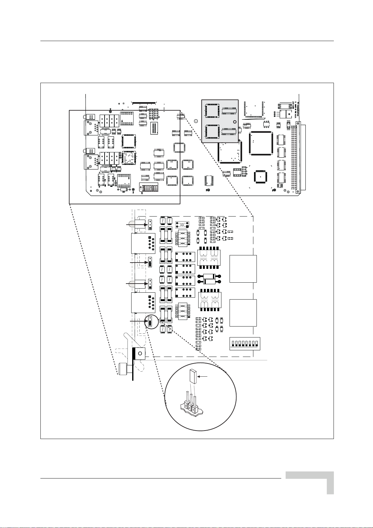
Configuring the E1 or T1 Trunk Card
9 Reconnect all disconnected cables to their proper ports on the E1 card.
Figure 2-6 shows the location of the grounding jumpers.
J7
12 435678
ON
RX
Ground
Port 0
Ground
RX
Ground
Port 1
Ground
TX
TX
RJ45
RJ45
P8P11P10 P9
2940
FUSE
FUSE
FUSE
FUSE
FUSE
FUSE FUSE
FUSE
555-
RELAY
+
RELAY
+
RELAY
+
RELAY
+
2940
555-
NONC
NONC
NONC
NONC
1:1.36
PE68822
1:2
1:2
PE68822
1:1.36
Jumper
Item No.0015
61
X
T
41
61
X
T
41
80
RX
BT-8370
80
RX
BT-8370
1
..... HOST .....
21
1
..... HOST .....
21
Jumper Position 1,2
For P8-P11
IW068004
Figure 2-6: Ground Jumpers (P8 through P11)
UltraWAVE Micro BTS Installation and Commissioning Guide, Version B 33
Page 50

Chapter 2 - Installation
2.3.2 Configuring Cable Length DIP Switch Settings
on T1 Cards
To configure the DIP switch settings on a T1 card:
1 Ensure that anti-static precautions are taken. Refer to Section 1.2 for
anti-static precautions.
2 Make note of the orientation of the cables and disconnect them from the
selected card.
3 Using a Phillips screwdriver, fully loosen the two captive screws located at the
top and bottom of the card.
4 Remove the T1 card by firmly pulling the two white tabs located at the top and
bottom of the card.
5 See Figure 2-7 to locate the DIP switch.
6 On T1 cards, the DIP switch setting is determined by the cable distance from
the card to the DSX-1 demarcation point. The following table provides the
appropriate Port 0 and Port 1 DIP switch settings for DSX-1 demarcation
points located within various cable distance ranges.
In Table 2-9, the first setting (0-133 ft.) is the default and should
be used for all T1 applications unless
demarcation point beyond 133 ft. When connecting two chassis
you will always use the first setting regardless of distance (up to
600 m).
Table 2-9: T1 DIP Switch Settings
Port 0
Switch Setting
1-2-3-4
OFF-ON-ON-ON OFF-ON-ON-ON 0-133 (0-40.57)
OFF-OFF-ON-ON OFF-OFF-ON-ON 133-266 (40.57-81.13)
OFF-ON-OFF-ON OFF-ON-OFF-ON 266-399 (81.13-121.7)
OFF-OFF-OFF-ON OFF-OFF-OFF-ON 399-533 (121.7-162.57)
OFF-ON-ON-OFF OFF-ON-ON-OFF 533-655 (162.57-199.78)
Port 1
Switch Setting
5-6-7-8
connecting to a DSX-1
Cable distance from T1 Card to
DSX-1 Demarcation Point
Feet (Meters)
Note: ON refers to the DIP switch pin being in the “UP” position and OFF refers to the
DIP switch pin being in the “DOWN” position. X = either ON or OFF.
34 UltraWAVE Micro BTS Installation and Commissioning Guide, Version B
Page 51

Configuring the E1 or T1 Trunk Card
ON
12 435678
7 Place the card into the slot and slide in the card until it completely rests inside
the slot. Push the card firmly into place.
8 Using a Phillips screwdriver, tighten the two captive screws into the chassis
through the trunk card.
Figure 2-7 shows the location of the DIP switch.
J4
12 435678
ON
J6
J8
J7
J9
IW180001
Figure 2-7: Location of DIP Switch on a T1 Trunk Card
UltraWAVE Micro BTS Installation and Commissioning Guide, Version B 35
Page 52

Chapter 2 - Installation
2.4 Connecting Ground Cables
Use this section to connect your earth ground and power cables to the Micro BTS
cabinet.
2.4.1 Connecting the Grounding Cable
The rack unit in which the Micro BTS subracks are being mounted should be
properly grounded to the site earth ground ring. You must attach a ground strap
to each subrack and to the rack unit or directly to the site ground ring.
1 Locate the ground lugs on each subrack assembly. See Figure 2-8 for their
location.
Figure 2-8: Ground Lugs
2 Remove the nut from each ground lug and connect a ground lead to each
subrack. Secure the nut tightly on each subrack assembly.
3 Attach the ground cables to the properly grounded rack assembly or to the
closest earth ground bus.
36 UltraWAVE Micro BTS Installation and Commissioning Guide, Version B
Page 53

2.4.2 Grounding the Cabinet
The subrack assemblies are grounded to the cabinet by the manufacturer. The
cabinet should be grounded to the site earth ground ring. Complete the following
to connect an earth ground to the chassis.
1 Route a customer-supplied 10 AWG (2.5 mm) or larger copper wire to a
grounding lug inserted into one of the M10 tap holes shown in Figure 2-5.
2 Connect the other end of the lead stud to the closest grounding bus.
Caution: Grounding circuit continuity is vital for safe operation of
machine. Never operate machine with grounding conductor
disconnected.
Attention: Un circuit de terre continu est essentiel en vue du
fonctionnement sécuritaire de l'appareil. Ne jamais metre
l'appareil en marche lorsque le cable de mise à la terre est
débranche.
Connecting Ground Cables
Warnung: Achtung, Hoher Ableitstrom! Schutzleiteranschluß vor
dem Netzanschluß herstellen.
UltraWAVE Micro BTS Installation and Commissioning Guide, Version B 37
Page 54

Chapter 2 - Installation
2.5 Connecting Power Supplies
In this section, you will connect the Micro BTS to your power source. Before
beginning it is necessary to first:
Identify your power configuration. This may be AC (110 V to 220 V, 30 A
50-60 Hz) or DC (-40 V to -60 V, 40 A).
Install your AC or DC power supplies.
When you have completed these tasks, refer to the appropriate subsection to
make either AC or DC power connections:
Connecting AC power. See Section 2.5.1
Connecting DC power. See Section 2.5.2
Warning: This product relies on the building's installation for
short-circuit (over current) protection. Ensure that a fuse or
circuit breaker no larger than 110 VAC, 30 A; 220 VAC, 15 A; or
-48 VDC, 40 A is used on the phase conductors (all
current-carrying conductors).
Attention: Pour ce qui est de la protection contre les
courts-circuits (surtension), ce produit dépend de l'installation
électrique du local. Vérifier qu'un fusible ou qu'un disjoncteur de
110 VAC, 30 A alt., 220 VAC, 15 A alt., -48 VDC 40 A est utilisé
sur les conducteurs de phase (conducteurs de charge).
Warnung: Dieses Produkt ist darauf angewiesen, daß im
Gebäude ein Kurzschluß- bzw. Überstromschutz installiert ist.
Stellen Sie sicher, daß eine Sicherung oder ein Unterbrecher von
nicht mehr als 110 V Wechselstrom, 30 A; 220 V Wechselstrom,
15 A; oder -48 V Gleichstrom, 40 A an den Phasenleitern (allen
stromführenden Leitern) verwendet wird.
Identifying AC and DC Power Configurations
You can determine whether your system uses AC or DC power by checking the
main configuration label. The main configuration label is located on either the
exterior of your shipping container or on the rear of the Micro subrack assembly.
See Section 1.3.1 for the details included on the main configuration label. Use
Table 1-1 to identify your system power configuration.
38 UltraWAVE Micro BTS Installation and Commissioning Guide, Version B
Page 55

Connecting Power Supplies
Figure 2-9 displays the AC power supply modules. Figure 2-10 displays the DC
power supply modules.
INPUT
OUTPUT
FAULT
UNLOCK
ON
OFF
OUTPUT
UNLOCK
INPUT
FAULT
ON
OFF
Figure 2-9: AC Power Supply Subrack Assembly
INPUT
OUTPUT
FAULT
OFF ON
INPUT
OUTPUT
FAULT
OFF ON
Figure 2-10: DC Power Supply Subrack Assembly
IW138601
IW138602
Installing AC Power Supply Modules
The customer ordered configuration determines the number of power supply
modules included with the Micro BTS. The power supply modules must be
installed according to the following procedure:
1 Remove the power supply module from the packaging.
2 Insert the power supply module in the first empty slot at the front left of the
subrack assembly.
3 Slide the power supply module into the chassis until it locks into place.
UltraWAVE Micro BTS Installation and Commissioning Guide, Version B 39
Page 56
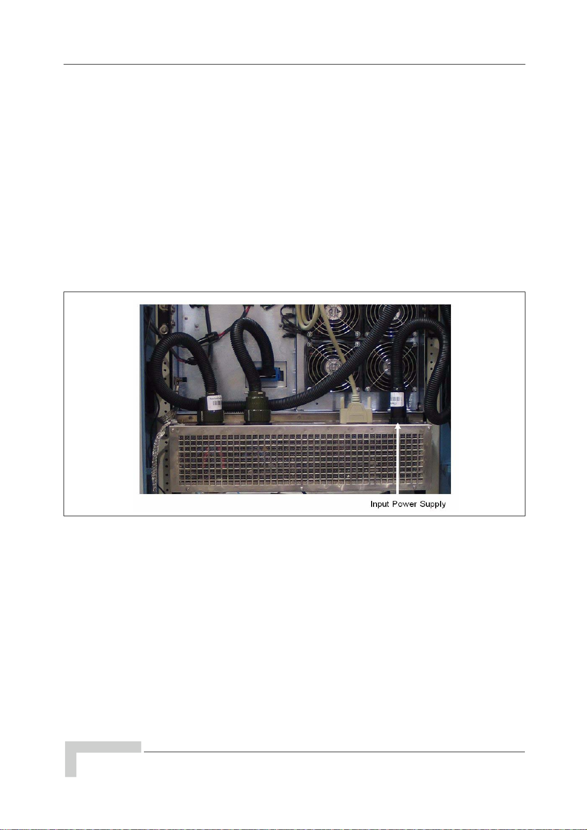
Chapter 2 - Installation
Installing DC Power Supply Modules
The customer ordered configuration determines the number of power supply
modules included with the Micro BTS. The power supply modules must be
installed according to the following procedure:
1 Remove the power supply module from the packaging.
2 Insert the power supply module in the first empty slot at the front left of the
subrack assembly.
3 Slide the power supply module into the chassis.
4 Twist the captive screws clockwise to secure the power supply module into
place. If you are connecting directly to the power supply subrack assembly,
Figure 2-11 shows the input power connector location.
Figure 2-11: Power Supply Subrack Connection
40 UltraWAVE Micro BTS Installation and Commissioning Guide, Version B
Page 57

2.5.1 Connecting AC P ower
The Micro BTS is shipped from the factory with the internal cabling routed from
the AC power supply subrack assembly to a round quick disconnect connector on
the top rear of the cabinet.
The input power connector cable is supplied with the cabinet assemblies.
Figure 2-12 shows the AC input power connector which attaches to the cabinet
enclosure.
Connecting Power Supplies
Figure 2-12: AC Input Power Connector and Cable
Connecting the AC Power Supply to the Cabinet
1 Verify the ground connection you made in Section 2.4.1 is secure.
2 Make sure that the power switch located on all power supply modules is in the
OFF position. See Figure 2-13 for the location of the power supply power
switches.
UltraWAVE Micro BTS Installation and Commissioning Guide, Version B 41
Page 58

Chapter 2 - Installation
OUTPUT
UNLOCK
INPUT
FAULT
ON
OFF
INPUT
OUTPUT
FAULT
UNLOCK
ON
OFF
Power Switches
IW138603
Figure 2-13: AC Power Supply Module ON/OFF Switches
3 Ensure the input power source is turned off and not supplying power to source
power connection.
4 Plug the power cable into the electrical mains or connect the flat washers,
shown in Figure 2-12, directly to the input power source, as follows:
White is the neutral lead
Black is the line lead
Green is the ground lead
5 Plug the round quick disconnect connector as illustrated in Figure 2-12 into
the power connection on the top of the cabinet as illustrated in Figure 2-14.
Secure the connector by twisting the connector sleeve until the lines on the
cable connector and chassis connector align.
If you have ordered the NIB as separate subrack assemblies, you will connect
the input power cable directly to the power supply subrack assembly, shown
in Figure 2-11.
6 Do not apply power to the chassis at this time. Wait until you are
performing the off-line commissioning procedures in the next chapter.
42 UltraWAVE Micro BTS Installation and Commissioning Guide, Version B
Page 59

Figure 2-14: AC Power Supply Chassis Connection
Connecting Power Supplies
Caution: The power supply cord is used as the main disconnect
device, ensure that the socket-outlet is located/installed near the
equipment and is easily accessible.
Attention: Le cordon d'alimentation est utilisé comme
interrupteur général. La prise de courant doit être située ou
installée à proximité du matériel et être facile d'accés.
Warnung: Das Netzkabel dient als Netzschalter. Stellen Sie
sicher, das die Steckdose einfach zugänglich ist.
The power supplies’ INPUT LEDs will illuminate and power
supply fans will start when connected to the power source. Do
not power on the cabinet at this time.
UltraWAVE Micro BTS Installation and Commissioning Guide, Version B 43
Page 60

Chapter 2 - Installation
2.5.2 Connecting DC Power
The Micro BTS is shipped from the factory with the internal cabling routed from
the DC power supply subrack assembly to a round quick disconnect connector on
the top rear of the cabinet.
The input power connector cable is supplied with the cabinet assemblies. This
section explains how to assemble the input power connector and cable.
DC Input Power Connector Details
Figure 2-15 shows the DC quick disconnect power connector and cable.
Figure 2-15: DC Round Quick Disconnect Connector and Cable
The cable wires are connected to the input power supply as follows:
Black is connected to the -48 VDC supply.
Red is connected to the -48 VDC supply.
White is a return and typically connected to the cabinet ground.
Green is a return and typically connected to the cabinet ground.
Two wires carry -48 VDC and two wires must carry Return.
44 UltraWAVE Micro BTS Installation and Commissioning Guide, Version B
Page 61

Connecting the DC Power Supply to the Cabinet
Use the following procedure:
The power main must be a Safe Extra-Low Voltage (SELV),
-48 VDC supply as defined in IEC950 and EN60950.
1 Verify the ground connection you made in Section 2.4.1 is secure. The cabinet
is grounded through this connection. It is critical that this connection is made
properly.
2 Make sure that the power button located on all power supply modules is in the
raised OFF position. See Figure 2-16 for the location of the power supply
power buttons.
Connecting Power Supplies
INPUT
OUTPUT
FAULT
OFF ON
INPUT
OUTPUT
FAULT
OFF ON
IW138604
Power Switches
Figure 2-16: DC Power Supply Module ON/OFF Switches
3 Verify the -48 VDC power source is off.
4 The -48 VDC power cable has two wires for negative (-) connection and two
wires for return (+) connection. This spreads the current draw across two pins
of the round quick disconnect connector for each connection.
5 Attach the two return (+) cables (white and green) to the positive side of your
-48 VDC power source or to ground if you are using a chassis ground for your
return.
6 Attach the two negative (-) cables (black and red) to the negative side of your
-48 VDC power source.
7 Plug the round quick disconnect connector as illustrated in Figure 2-15 into
the power connection on the top of the cabinet as illustrated in Figure 2-17.
Secure the connector by twisting the connector sleeve until the lines on the
cable connector and chassis connector align.
UltraWAVE Micro BTS Installation and Commissioning Guide, Version B 45
Page 62

Chapter 2 - Installation
8 Do not apply power to the chassis at this time. Wait until you are
performing the off-line commissioning procedures in the next chapter.
Figure 2-17: Power Supply Connection
Caution: The power supply cord is used as the main disconnect
device, ensure that the socket-outlet is located/installed near the
equipment and is easily accessible.
Attention: Le cordon d'alimentation est utilisé comme
interrupteur général. La prise de courant doit être située ou
installée à proximité du matériel et être facile d'accés.
Warnung: Das Netzkabel dient als Netzschalter. Stellen Sie
sicher, das die Steckdose einfach zugänglich ist.
The power supplies’ INPUT LEDs will illuminate and power
supply fans will start when connected to the power source. Do
not power on the cabinet at this time.
46 UltraWAVE Micro BTS Installation and Commissioning Guide, Version B
Page 63

Connecting E1 or T1 Trunk Cables
2.6 Connecting E1 or T1 Trunk Cables
External trunk cabling depends on the configuration that the customer ordered
and the site-specific requirements. These cables will be supplied by the customer.
Failure to use electrically compliant T1 or E1 cables may cause transmission
errors. Please refer to the appropriate subsections to determine your cable
requirements.
The E1 or T1 trunk cables are routed directly to the E1 or T1 trunk card in the
Micro subrack assembly. All three types of signaling (E1 75 Ohm, E1 120 Ohm
and T1 100 Ohm) are terminated at the cabinet with RJ-48C port connectors.
2.6.1 E1 Cables
E1-75 Ohm
This is coaxial cable with a nominal impedance of 75 Ohm +/-5% at 1 MHz. The
maximum allowable cable distance depends directly on the insertion loss of the
cable at 1 MHz. In this mode, the E1 trunk card can accommodate up to 6 dB of
cable loss.
E1-120 Ohm
This cable is individually shielded twisted pair with a nominal impedance of
120 Ohm +/-5% at 1 MHz. The maximum allowable cable distance depends
directly on the insertion loss of the cable at 1 MHz. In this mode, the E1 trunk
card can accommodate up to 9 dB of cable loss.
Table 2-10 provides a description of cables required for installation and
connection to an E1 network, but not supplied with the Micro BTS.
Before connecting E1 lines to the Micro BTS, it is assumed that
the quality of the lines has been verified. It is recommended that
Bit Error Ratio (BER) tests are completed to ensure that the BER
is less than 10
-8
.
UltraWAVE Micro BTS Installation and Commissioning Guide, Version B 47
Page 64

Chapter 2 - Installation
Table 2-10: Customer-Supplied E1 Cabling
Cable Identity Cable Type Corresponding Cable Plug
E1, 120 Ohm Shielded, Twisted, 2-Pair RJ-48C Male
E1, 75 Ohm Coaxial RJ-48C Male
Antenna (external) Coaxial N-Type, Female
Note: The number of cables required depends on the ordered configuration of the
Micro BTS.
Conversion Cables
If you are connecting into an existing E1 network with standard BNC or DSUB
connectors, a conversion cable for either the 75 Ohm or 120 Ohm will be required.
To purchase these cables from Alvarion, contact your local sales support
representative.
J2
RECEIVE
TRANSMIT
J3
J2
J3
BLUE/WHITE
WHITE/BLUE (R-TIP)
ORANGE/WHITE
WHITE/ORANGE
(R-RING)
(T-RING)
(T-TIP)
J1
1
2
3
4
5
6
7
8
J1
Pin 1
Pin 8
IW009302
Figure 2-18: 75 Ohm BNC Conversion Cable
Figure 2-18 illustrates the pinout for an RJ-48C to 75 Ohm BNC conversion cable.
48 UltraWAVE Micro BTS Installation and Commissioning Guide, Version B
Page 65

Connecting E1 or T1 Trunk Cables
Pin 15 Pin 8
Pin 9
Pin 1
J2
11
3
9
1
Figure 2-19: 120 Ohm Conversion Cable
Figure 2-19 illustrates the pinout for the RJ-48C to DSUB 120 Ohm conversion
cable.
2.6.2 T1 Cables
J2
BLUE/WHITE
WHITE/BLUE (R-TIP)
ORANGE/WHITE
WHITE/ORANGE
(R-RING)
(T-RING)
(T-TIP)
J1
1
2
3
4
5
6
7
8
Pin 1
Pin 8
IW009303
J1
T1-100 Ohm
For T1 connections, the proper cable is an individually shielded twisted pair with
a nominal impedance of 100 Ohm +/-5% at 772 kHz. The maximum allowable
cable distance depends directly on the insertion loss of the cable at 772 kHz. The
T1 card can accommodate up to 9 dB of cable loss. When using 22 AWG ABAM
cable, 9 dB of loss is approximately 2000 feet. When using Belden type 9729 (with
a cable loss of 6 dB per 1000 feet at 772 kHz) the maximum cable distance is
approximately 1500 feet.
Table 2-11 provides a description of cables required for installation and
connection to a T1 network, but not supplied with the Micro BTS.
Before connecting T1 lines to the Micro BTS, it is assumed that
the quality of the lines has been verified. It is recommended that
BER tests be completed to ensure that the BER is less than 10
-8
.
UltraWAVE Micro BTS Installation and Commissioning Guide, Version B 49
Page 66

Chapter 2 - Installation
Table 2-11: Customer-Supplied T1 Cabling
Cable Identity Cable Type Corresponding Cable Plug
T1, 100 Ohm Shielded, Twisted, 2-Pair RJ-48C, Male
Note: The number of cables required depends on the ordered configuration of the
Micro BTS.
2.6.3 Connecting E1 or T1 Lines
All E1 or T1 cable routing should be installed per the site survey documentation
in conjunction with the information identified in the GSM Network
Implementation Manual.
Using the appropriate customer-supplied cables, connect the Abis interface E1
and/or T1 cables to the local E1 or T1 provider.
2.6.4 Direct Cabling Between Multiple UltraWAVE
or WAVEXpress Systems
This section provides information for cabling between Alvarion equipment. The
external cabling between your equipment will vary depending on the configuration
of the cable management assembly of each chassis. This could consist of any
combination of BNC, DSUB or RJ-48C connectors and either E1 or T1 signaling.
The direct cabling between systems requires crossover cables (Tx
to Rx, and Rx to Tx), instead of the straight-through cabling used
when connecting systems through a radio or telephone provider
network.
50 UltraWAVE Micro BTS Installation and Commissioning Guide, Version B
Page 67
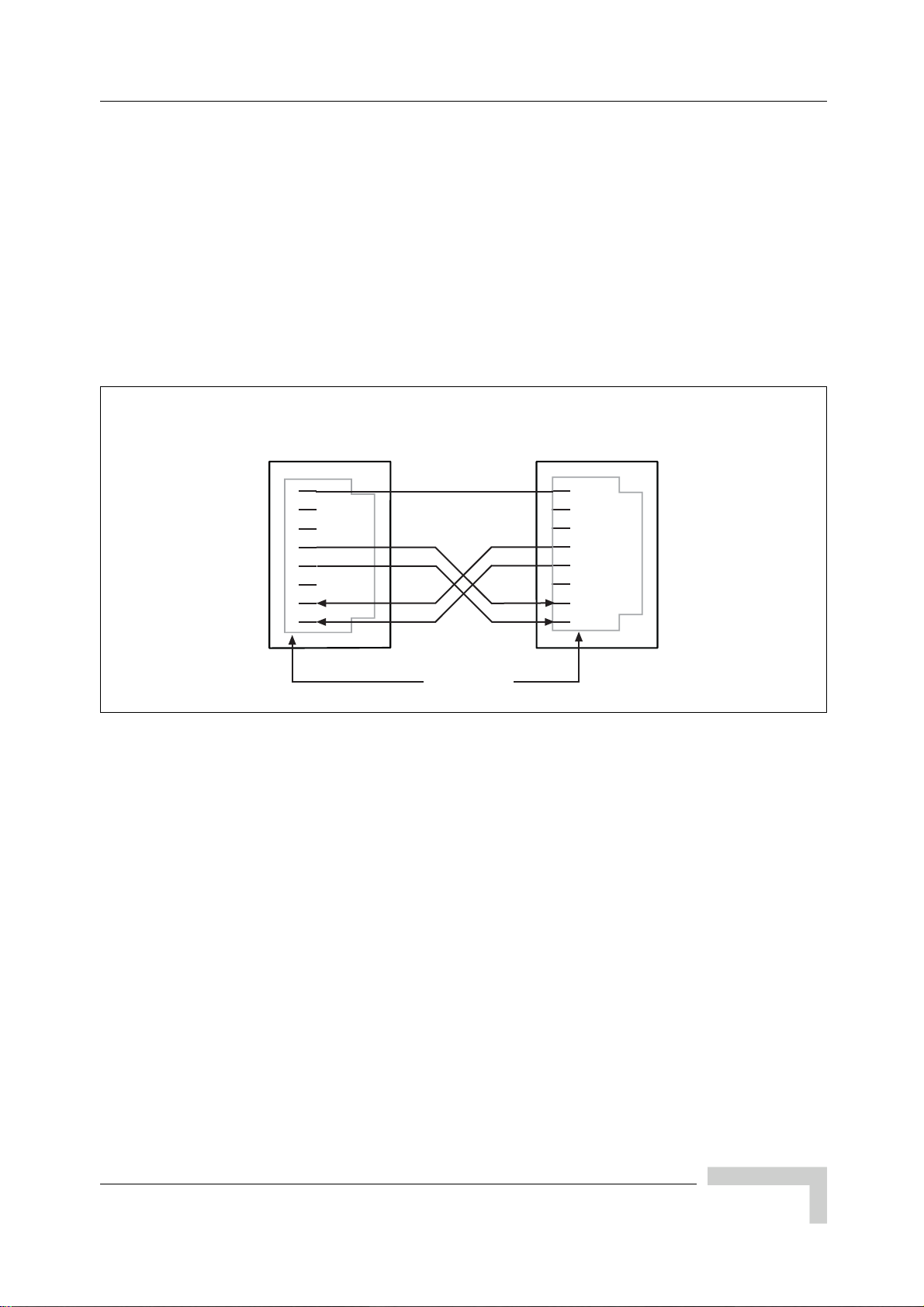
Using Cross-Over RJ-48C Cables
When connecting a shielded twisted pair crossover cable between two UltraWAVE
or WAVEXpress systems, the routing of the pins needs to comply with the cable
mapping shown in Figure 2-20. The RJ-48C cable connector may be of the
conventional plastic body type with the shield and drain wires of the cable
connected to a pigtail to pin 8 (Signal Ground), which is internally grounded to the
card. However, a shielded cable plug may also be used, terminating the cable
shield to an integral metal shell of the RJ-48 jack which then makes an electrical
connection to the front panel when installed. Figure 2-20 provides the pin
assignments for the RJ-48C jacks.
Connecting E1 or T1 Trunk Cables
Pin 5: Transmit Tip
Pin 4: Transmit Ring
Pin 2: Receive Tip
Pin 1: Receive Ring
To connect two systems using RJ-48C cables, connect a crossover cable (see
Figure 2-20) from port 1 of the first chassis to port 0 of the second chassis.
T1 or E1 Port
Connector
8
7
6
5
4
3
2
1
PCB Signal
Ground
Pin Numbers
T1 or E1 Port
Connector
8
7
6
5
4
3
2
1
Figure 2-20: Cable Mapping of RJ-48C Crossover Cable
Pin 5: Transmit Tip
Pin 4: Transmit Ring
Pin 2: Receive Tip
Pin 1: Receive Ring
IW140401
UltraWAVE Micro BTS Installation and Commissioning Guide, Version B 51
Page 68

Chapter 2 - Installation
2.7 Connecting Antennas
The cabinet assembly provides external access to the male N-type connectors for
your external antennas. Your antenna cable should terminate with a 90° N-type
female connector or an N-type female to male elbow adapter may be used for a
more convenient connection to the cabinet. Insertion loss for the elbow type of
connector is typically between 0.1 and 0.2 dBm.
The antenna cabling for the Micro BTS can be configured in several ways
depending on a number of factors including the number of TRXs, number of
antennas and use of diversity. Your site specific configuration was determined
during the network planning stage of implementation.
Table 2-12: Customer-Supplied Adapters and Cabling
Identity Cable Type Corresponding Cable Plug
Antenna cable
(external)
Coaxial N-type, Female
Adapter (optional) 90 degree elbow N-type Female to N-type Male
Note: The number of cables required depends on the ordered configuration of the
Micro BTS.
In the subsequent sections, each RF configuration is detailed from the RF module
connector to the internal RF connector. Figure 2-21 illustrates the relationship
between the three connectors. The RF modules are connected to the internal RF
connectors at the factory and are pre-configured for your Micro BTS
configuration.
External RF Connectors
(Top of Cabinet)
Internal RF Connectors
(with port number)
RF Module Connectors
01 23 54
ANT
ANT
MAIN
DIV
PWR
FLT
RX1
RX1
ON LINE
RX2
RX2
ON
RX3
RX3
OFF
RX4
RX4
ANT
ANT
MAIN
DIV
PWR
FLT
RX1
RX1
ON LINE
RX2
RX2
ON
RX3
RX3
OFF
RX4
RX4
ANT
ANT
MAIN
DIV
PWR
FLT
RX1
RX1
ON LINE
RX2
RX2
ON
RX3
RX3
OFF
RX4
RX4
IW009304
Figure 2-21: Antenna Cabling for Standard BTS Configurations
You will attach an elbow connector and your antenna cable to the external RF
connector associated with the internal RF connector shown in the appropriate
figure.
52 UltraWAVE Micro BTS Installation and Commissioning Guide, Version B
Page 69

Connecting Antennas
The subsequent sections identify the cable routing for the different Micro BTS
antenna configurations that you identified in Chapter 1 - Unpacking and
Configuration Verification. You must install the antennas such that the general
population is kept at least 164 inches from the main beam of the antenna. For
more information on the RF radiation properties of the UltraWAVE, refer to
Section 2.7.6.
Proceed to the appropriate subsection to connect your site-specific antenna cable
configuration.
All RF cabling must be completed with the chassis powered off
and, preferably, with the power cable disconnected from the
cabinet.
Do not disconnect RF coaxial connectors on the Alvarion
equipment or antenna systems while the radio equipment is
operating.
Never place any body part over or look into any RF
connector while the radio equipment is transmitting.
RF signal levels that give rise to hazardous radiation levels can
exist within the transmitter, power amplifiers, associated RF
multiplexers and antenna systems.
UltraWAVE Micro BTS Installation and Commissioning Guide, Version B 53
Page 70

Chapter 2 - Installation
2.7.1 Omni 1 TRX (O1) Configuration
The Omni 1 TRX (01) configuration is available as a 15 Watt, 25 Watt, 40 Watt or
a 50 Watt, two antenna configuration. See Table 2-13.
Table 2-13: Omni 1 TRX (01) Configuration
Output Power Available Frequencies
15 W (42 dBm) 1800 MHz, 1900 MHz
25 W (44 dBm) 850 MHz, 900 MHz
40 W (46 dBm) 1800 MHz, 1900 MHz
50 W (47 dBm) 850 MHz, 900 MHz
For the 15 Watt, 25 Watt, 40 Watt, 50 Watt Omni 1 TRX (01) configurations,
connect your antennas as shown in Figure 2-22.
/a
Antenna 1
Diversity
Antenna 1
Main
Antenna connection
External RF connector
Internal RF connector
RF modules
1 2 3 4 50
A
B
Not UsedNot Used Not Used Not Used
ANT
DIV
ANT
MAIN
C
Figure 2-22: Antenna Cabling for O1 Configuration
2.7.2 Omni 2 TRX (O2) Configuration
The Omni 2 TRX (02) configuration is available as a 15 Watt, 25 Watt, 40 Watt or
a 50 Watt, two antenna configuration. See Table 2-14.
Table 2-14: Omni 2 TRX (02) Configuration
Output Power Available Frequencies
15 W (42 dBm) 1800 MHz, 1900 MHz
IW130601
25 W (44 dBm) 850 MHz, 900 MHz
40 W (46 dBm) 1800 MHz, 1900 MHz
50 W (47 dBm) 850 MHz, 900 MHz
54 UltraWAVE Micro BTS Installation and Commissioning Guide, Version B
Page 71

Connecting Antennas
For the 15 Watt, 25 Watt, 40 Watt and 50 Watt Omni 2 TRX (02) configurations,
connect your antennas as shown in Figure 2-23.
Antenna 1
Diversity
Antenna 1
Main
Antenna connection
Not UsedNot Used Not Used Not Used
External RF connector
Internal RF connector
1 2 3 4 50
ANT
DIV
ANT
MAIN
RF modules
A
B
C
Figure 2-23: Antenna Cabling for O2 Configuration
2.7.3 Omni 3 TRX (O3) Configuration
The Omni 3 TRX (03) configuration is available as a 15 Watt or a 25 Watt, two
antenna configuration. See Table 2-15.
IW130601
Table 2-15: Omni 3 TRX (03) Configuration
Power Output Av ai la bl e Fre q ue n cies
15 W (42 dBm) 1800 MHz, 1900 MHz
25 W (44 dBm) 850 MHz, 900 MHz
For both the 15 Watt and 25 Watt Omni 3 TRX (03) configurations, connect your
antennas as shown in Figure 2-24.
UltraWAVE Micro BTS Installation and Commissioning Guide, Version B 55
Page 72

Chapter 2 - Installation
Antenna connection
External RF connector
Internal RF connector
RF modules
Figure 2-24: Antenna Cabling for O3 Configuration
For the Omni 3 TRX (03), a spatial diversity of 10 lambdas is
required between antennas.
Antenna 1
Main
Antenna 2
Main
Not UsedNot Used Not Used Not Used
1 2 3 4 50
ANT
ANT
ABC
IW130603
56 UltraWAVE Micro BTS Installation and Commissioning Guide, Version B
Page 73

Connecting Antennas
2.7.4 Sectorized Three TRX (S111) Configuration
The sectorized three TRX (S111) configuration is available as a 15 Watt, 25 Watt,
40 Watt or a 50 Watt six antenna configuration. See Figure 2-16.
Table 2-16: Sectorized Three TRX (S11) Configuration Frequencies
Configurations Available Frequencies
15 W (42 dBm) 1800 MHz, 1900 MHz
25 W (44 dBm) 850 MHz, 900 MHz
40 W (46 dBm) 1800 MHz, 1900 MHz
50 W (47 dBm) 850 MHz, 900 MHz
This configuration has three sectors with one TRX per sector. For the 15 Watt,
25 Watt, 40 Watt and 50 Watt configurations, connect your antennas as shown in
Figure 2-25.
Antenna connection
External RF connector
Internal RF connector
RF modules
Figure 2-25: Antenna Cabling for S111 Configuration
Antenna 1
Diversity
ANT
DIV
Antenna 1
Main
Antenna 2
Diversity
Antenna 2
Main
Antenna 3
Diversity
1 2 3 4 50
ANT
MAIN
ANT
DIV
ANT
MAIN
ANT
DIV
ANT
MAIN
ABC
Antenna 3
Main
IW130611
UltraWAVE Micro BTS Installation and Commissioning Guide, Version B 57
Page 74

Chapter 2 - Installation
2.7.5 Thr ee Sector Six TRX (S222) Configuration
The three sector, six TRX (S222) configuration is available as a 15 Watt, 25 Watt,
40 Watt or a 50 Watt, six antenna configuration. See Table 2-17.
Table 2-17: Three Sector Six TRX (S222) Configuration Frequencies
Configuration Available Frequencies
15 W (42 dBm) 1800 MHz, 1900 MHz
25 W (44 dBm) 850 MHz, 900 MHz
40 W (46 dBm) 1800 MHz, 1900 MHz
50 W (47 dBm) 850 MHz, 900 MHz
This configuration has three sectors with two TRXs in one sector and one TRX in
the other two sectors. For the 15 Watt, 25 Watt, 40 Watt and 50 Watt S222
configurations, connect your antennas as shown in Figure 2-26.
Antenna 1
Diversity
Antenna 1
Main
Antenna 2
Diversity
Antenna connection
External RF connector
ANT
MAIN
1 2 3 4 50
ANT
DIV
Internal RF connector
ANT
DIV
RF modules
ABC
Figure 2-26: Antenna Cabling for S222 Configuration
2.7.6 RF Radiation Hazard
As of October 15, 1997, all products must address the issue of Human Exposure
to RF electromagnetic fields. Referring to OET Bulletin 65, RF radiation limits for
the 300 - 1500 MHz range are f / 300 mW/cm
1500 mW/cm
the 869 MHz cellular band these limits are 2.90 mW/cm
exposure, and 0.58 mW/cm
2
for general population exposure (where f is frequency in MHz). At
2
for general population exposure.
ANT
MAIN
Antenna 2
Main
ANT
DIV
2
for occupational exposure, and f /
Antenna 3
Diversity
ANT
MAIN
2
for occupational
Antenna 3
Main
IW130611
The UltraWAVE base station may consist of up to six separate transceivers, with
each of the transmitters operating at a maximum output power of +47 dBm
58 UltraWAVE Micro BTS Installation and Commissioning Guide, Version B
Page 75

Connecting Antennas
(50 W). The UltraWAVE base station transmitters operate in the U.S. cellular band
of 869 to 894 MHz.
As the UltraWAVE is intended to be operated in cellular service, each of its
transmitters is typically connected to a 65 - 120 degree sector antenna or omni
directional antenna. For the purpose of the MPE calculations, it will be assumed
that the UltraWAVE is fully equipped with six transceivers, and that two different
transmitters are used in each 120 degree sector. For the MPE calculations this
would be the worst case radiation levels as the equivalent RF power of +50 dBm
(100 Watt) would be transmitted into a 120 degree sector.
The typical gain of 65 - 120 degree sector antenna is in the range of +6 to +18 dBi.
However, there is the highest ERP limitation on the Part22 requirement which is
500 Watt (57 dBd).
The duty cycle of the transmitter is 100%. Assuming two transmitters are
operating into the same 120 degree sector, a maximum of +47 dBm of RF energy
would be transmitted into two antennas, with total EIRP=61 dBi would be the
worst case.
RF power density can be calculated with the equation: S = P * G / 4p R
2
, where
S = power density in mW/cm, P = power input to the antenna in mW, G = power
gain of the antenna, and R = distance to the center of radiation of the antenna in
cm. By rearranging this equation, the relationship between distance (R) and Power
Density (S) can be found.
Rearranging R = sqrt (PG/4pS), and solving for the maximum limits of
2.90 mW/cm
R(2.90 mW/cm
R(0.58 mW/cm
2
, and 0.58 mW/cm2 we have:
2
) = sqrt (1,260,000 mW/4p*2.90) = 186 cm, or 73 inches.
2
) = sqrt (1,260,000 mW/4p*0.58) = 416 cm, or 164 inches.
1,260,000 mW is used to account for two 50,000 mW
transmitters operating into each 120 degree sector.
These results show that the general population RF exposure limits are not
exceeded as long as the general population is kept 164 inches from the feed point
of the antenna.
The propagation characteristics at 870 MHz dictate a line-of-sight type of RF path.
As such, typical installation locations are up on rooftops or masts to get above
ground level path obstructions. When the UltraWAVE antennas are installed in
this manner, the general population will be further than 164 inches from the
antenna, and RF exposure limits will be met.
UltraWAVE Micro BTS Installation and Commissioning Guide, Version B 59
Page 76

Chapter 2 - Installation
2.8 Connecting External Alarms
The OMC supports many alarms from the Micro BTS. The external alarms are
reflected at the OMC operator station, and may be used for site alarms, such as
open door, temperature and battery back-up alarms. These customer defined
alarms are sampled every two minutes by default and will report an alarm when
sent by the Micro BTS alarm controller.
Using the details provided in these sections, make your connections for external
alarm inputs.
If you are replacing an existing system which has external alarms
connected directly to the processor card, you may connect your
existing RJ-45 alarm cable directly into the ICP processor card
alarm connector. Optionally, you can re-route your existing
alarms to the UltraWAVE alarm terminal block or add additional
external alarms.
The OMC operator can set the alarm text as described in the UltraVIEW OMC
Setup and System Administration Guide.
Identifying the Terminal Block
The alarms are processed on the alarm interface module located on the rear of the
Micro subrack assembly. The alarm interface module has connections for
incoming signals from external alarms and the power supplies and an outgoing
connection to the ICP processor card through a USB type cable. The interfaces are
shown in Figure 2-27.
60 UltraWAVE Micro BTS Installation and Commissioning Guide, Version B
Page 77

Connecting External Alarms
External Alarm
Interface
EP1 EP2 EP3 EP4 EP5 EP6 EP7 EP8 EP9 EP10 EP11 EP12 EP13 EP14 EP15 EP16
EP17 EP18 EP19 EP20
Power Supply
Alarm Interface
IW136601
Figure 2-27: Alarm Interface Module
This terminal block provides a plug connection for up to 17 external alarms. The
plugs supplied with the Micro BTS provide an alarm loop for connection to a
normally open alarm mechanism. The plug identifiers correspond to the alarm
codes sent to the OMC. See Table 2-18 for Terminal Block pin assignments, and
see Figure 2-28 for external alarm terminal block details.
Pin 1
(signal)
Plug
Identifier
Pin 2
(ground)
EP1 EP2 EP3 EP4 EP5 EP6 EP7 EP8 EP9 EP10 EP11 EP12 EP13 EP14
FC1 FC2 FC3 TTL 27v VCC DR VCC
EP15 EP16 EP17 EP18 EP19 EP20
IW191604
Figure 2-28: Customer-Defined External Alarm Connections
UltraWAVE Micro BTS Installation and Commissioning Guide, Version B 61
Page 78

Chapter 2 - Installation
Table 2-18: External Alarm Terminal Block Pin Assignment
Plug Identifier Alarm Code Major Alarm Type
EP1 2326 Customer definable UltraWAVE External Alarm 1
EP2 2327 Customer definable UltraWAVE External Alarm 2
EP3 2328 Customer definable UltraWAVE External Alarm 3
EP4 2329 Customer definable UltraWAVE External Alarm 4
EP5 2330 Customer definable UltraWAVE External Alarm 5
EP6 2331 Customer definable UltraWAVE External Alarm 6
EP7 2332 Customer definable UltraWAVE External Alarm 7
EP8 2333 Customer definable UltraWAVE External Alarm 8
EP9 2334 Customer definable UltraWAVE External Alarm 9
EP10 2335 Customer definable UltraWAVE External Alarm 10
EP11 2336 Customer definable UltraWAVE External Alarm 11
EP12 2337 Customer definable UltraWAVE External Alarm 12
EP13 2338 Customer definable UltraWAVE External Alarm 13
EP14 2339 Customer definable UltraWAVE External Alarm 14
EP15 2340 Customer definable UltraWAVE External Alarm 15
EP16 2341 Customer definable UltraWAVE External Alarm 16
EP17 2342 Customer definable UltraWAVE External Alarm 17
62 UltraWAVE Micro BTS Installation and Commissioning Guide, Version B
Page 79
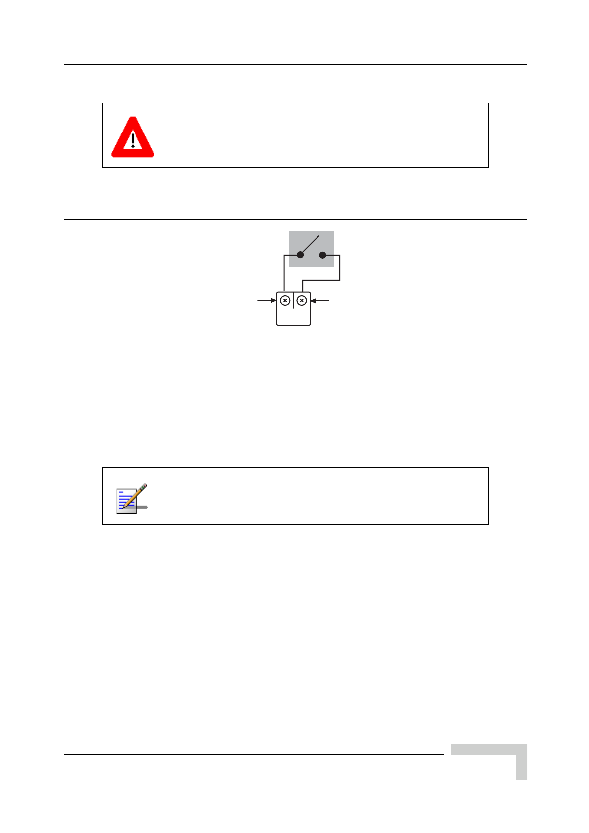
Connecting External Alarms
To connect the external alarm contacts to the external alarm terminal block:
Only the EP1 through EP17 plugs shown in Figure 2-28 use the
signal and ground alarm input pins. DO NOT connect EP1
through EP17 plugs to FC, TTL, 27V, VCC or DR connection
pins, or you can cause serious damage to the system.
1 Route the external alarm input cables from the external equipment through
the cable gland on the external interface to the external alarm terminal block.
Pin 1
(signal)
Pin 2
(ground)
IW022302
Figure 2-29: External Alarm Plug
2 Using the details provided in Figure 2-29, connect the normally-open alarm
inputs from the external equipment to the external alarm plug.
3 Connect the alarm plug to the terminal block. Note the plug identifier and
using Table 2-18 inform the OMC operator which alarm code corresponds to
the external alarm that you have just installed.
Inputs from external alarms should be normally open. When the
external contacts close, the Micro BTS sends an alarm to the
OMC.
UltraWAVE Micro BTS Installation and Commissioning Guide, Version B 63
Page 80

Chapter 2 - Installation
2.9 Making a Serial Connection to the Processor Card
The serial connection is used to check the software version installed on the
processor card, verify boot parameters and monitor test results. An RJ-11 to
RJ-11 cable and an RJ-11 to DB-9 adapter is normally used to connect the Craft
PC to the ICP CON serial port. This hardware is supplied in the Craft PC
Accessories kit.
This adapter is not included with the Craft PC accessories kit.
See Figure 2-30 for the ICP CON serial port pin-out.
9
8
RS232 DCD
RS232 TXD
RS232 RXD
7
6
5
4
3
2
1
10
RJ-45
IW044302
Figure 2-30: ICP Serial Pin-Out
For more information pertaining to pinouts and cables, please
refer to the GSM Craft PC Guide
.
64 UltraWAVE Micro BTS Installation and Commissioning Guide, Version B
Page 81

2.10 Network Connections
External cabling is dependent upon the customer-ordered configuration and
site-specific requirements. These cables will be supplied by the customer. Failure
to use electrically compliant T1 or E1 cables may cause transmission errors.
Please refer to the appropriate subsections to determine your cable requirements.
Installing the Physical E1 or T1 Links
For the first E1 or T1 link between the Micro BTS and the BSC, connect Port 0 of
the Micro BTS E1 or T1 card in slot 1 to the BSC. For additional E1 or T1 links,
you can use any other port on any other Micro BTS (or BTS) E1 or T1 card. After
connecting the E1 or T1 link(s) between the Micro BTS and the BSC, connect the
BSC to the OMC.
The E1 or T1 connections at the trunk cards and the BSC must
comply with the pin assignments detailed in Chapter 2 -
Installation. This chapter also explains the E1 or T1 trunk card
DIP switch, which must be set to reflect the E1 or T1 cable
characteristics.
Network Connections
Commissioning the E1 or T1 Links
The E1 or T1 links between the Micro BTS and the BSC are commissioned using
the W&G (Wandel & Goltermann) PA-25 multifunction communication analyzer,
or equivalent.
UltraWAVE Micro BTS Installation and Commissioning Guide, Version B 65
Page 82

Chapter 2 - Installation
2.11 Post Installation Cabling and Checks
You should ensure that all internal and external cabling is correctly connected.
2.11.1 Connecting the Chassis
Before commissioning the equipment, ensure that:
The Abis interface E1 and/or T1 cables are routed to the telephone provider.
The DIP switch settings on the E1 or T1 trunk cards are set correctly and if
you are using the 75 Ohm E1 trunk card that the ground jumper is in the
correct position. Refer to Section 2.3 for E1 and/or T1 DIP switch settings.
The chassis power is turned off.
Antenna cables are connected to RF antenna port connectors as appropriate.
2.11.2 Verifying External Cabling
It is the operator's responsibility to verify that all inter-chassis E1 and/or T1
links are ordered, installed and certified by the telephone provider according to
ANSI T1.403 specifications before on-line commissioning is performed.
The operator should also perform end-to-end bit error ratio or Bit Error Rate
(BER) tests over a 20-minute period on the E1 and T1 Abis interface link(s),
and verify that the BER is 10
-8
or better.
66 UltraWAVE Micro BTS Installation and Commissioning Guide, Version B
Page 83

Chapter 3 - Off-Line Commissioning
In this Chapter:
“Pre Off-Line Commissioning” on page 69
“Off-Line Commissioning of the Micro BTS” on page 71
“Software Verification using Craft PC” on page 83
“Upgrading the Micro BTS Software Version (Flash)” on page 90
“Post Off-Line Commissioning” on page 92
3
The off-line commissioning process includes the following steps:
Pre off-line commissioning, where you ensure that the system is in an appro-
priate state. This includes:
Visual inspection
Compliance checks
Startup verification, where you verify that the system boots up correctly by
observing the LEDs on the front panel.
Craft PC tests, where you use the Craft PC to verify the software configuration
and run tests.
Post off-line commissioning, where you prepare the system for on-line
commissioning.
The rest of this chapter includes detailed instructions for these steps.
Page 84

Chapter 3 - Off-Line Commissioning
Under normal operating conditions, Alvarion Communications
radio equipment complies with the limits for human exposure to
radio frequency (RF) fields adopted by the Federal
Communications Commission (FCC). All Alvarion
Communications, Inc. radio equipment is designed so that under
normal working conditions radio frequency radiation directly
from the radio is negligible when compared with the permissible
limit of continuous daily exposure recommended in the United
States of America by ANSI/IEEE C95.1-19991 (R1997), Safety
Levels with Respect to Human Exposure to RF Electromagnetic
Fields, 3 kHz to 300 GHz.
RF signal levels that give rise to hazardous radiation levels can
exist within the transmitter, power amplifiers, associated RF
multiplexers and antenna systems.
Do not disconnect RF coaxial connectors on the Alvarion
equipment or antenna systems while the radio equipment is
operating.
connector while the radio equipment is transmitting.
Never place any body part over or look into any RF
The BSS software used in the UltraWAVE Micro BTS is highly
complex.
that you have the latest available software. You must
correct software CD-ROM and
your software version before commissioning the UltraWAVE
Micro BTS. Contact your Level 2 support representative for
additional assistance.
The off-line commissioning steps are listed in Checklist 3 -
Commissioning Checklist.
Before proceeding, contact Customer Service to verify
have the
know the current patch level for
68 UltraWAVE Micro BTS Installation and Commissioning Guide, Version B
Page 85

3.1 Pre Off-Line Commissioning
The following sections must be completed before doing the off-line commissioning.
The off-line commissioning of the Micro BTS must take place on-site after
installation. It is critical that all RF connections have been completed before
proceeding with the off-line commissioning.
3.1.1 Visual Inspections
Complete the following inspections to ensure that the system is ready for off-line
commissioning.
On-Site Visual Inspection
If you are doing your visual inspection on-site, check that:
The chassis has been securely installed at the appropriate site.
Pre Off-Line Commissioning
The chassis power supplies are OFF.
The chassis is connected to a suitable power source.
Power supply fans are running and INPUT LEDs are illuminated.
The chassis is correctly grounded.
All cables are available and secured in their correct positions.
All cards and modules are correctly seated and populated according to the
original purchase order.
E1 or T1 transmission cables are available and labeled.
RF transmission cables are connected to antennas.
Compliance and Power Checks
Cross-check with the site specific data to ensure that the Micro BTS is
correctly configured with all cards and modules.
Ensure that you have access to Checklist 2 - Installation Checklist and that all
serial numbers of all cards are listed there. This should have been completed
in Chapter 1 - Unpacking and Configuration Verification.
Verify that any test equipment to be used has a current calibration certificate.
Verify that the voltage for the installation site match those of the chassis
power supply modules (either 230 VAC, 110 VAC, or -48 VDC, as specified on
the front panel).
UltraWAVE Micro BTS Installation and Commissioning Guide, Version B 69
Page 86

Chapter 3 - Off-Line Commissioning
Label and Disconnect Cables
1 Verify that all E1 or T1 cables connected to the chassis are properly labeled.
2 Disconnect all E1 or T1 cables from the top of the cabinet if there are any
cables connected.
70 UltraWAVE Micro BTS Installation and Commissioning Guide, Version B
Page 87

Off-Line Commissioning of the Micro BTS
3.2 Off-Line Commissioning of the Micro BTS
The verification procedures for off-line commissioning are run on the processor
card in the Micro BTS. Locate the processor card in the Micro BTS subrack
assembly as shown in Figure 3-1.
ANT
ANT
MAIN
DIV
PWR
FLT
RX1
ON LINE
RX2
ON
RX3
OFF
RX4
TX1
DET
PA1
IN
TX2
DET
PA2
IN
01234567
IIIIIIIIIIIIIIIIIIIIIIIII
RX1
P/N XXXXXX
I2C
RX2
RX3
RX4
PWR
TX
TX
ON
OUT
OUT
LINE
PWR
FLT
ONLINE
FLT
120 OHM
SCN
ENET
ALARMS
12
CON
PORT 0
ALARMS
IIIIIIIIIIIIIIIIIIIIIIIII
TX1
P/N XXXXXX
12
IIIIIIIIIIIIIIIIIIIIIIIII
DET
S/N XXXXXX
PORT 1
PA1
IN
IIIIIIIIIIIIIIIIIIIIIIIII
S/N XXXXXX
TX2
DET
PA2
IN
13 MHZ
13 MHZ
13 MHZ
CLK
CLK
RX-A
RX-A
DET
DET
IN
IN
PWR
PWR
ON LINE
ON LINE
FLT
FLT
RX-B
RX-B
TX
OUT
CLK
RX-A
DET
IN
PWR
ON LINE
FLT
RX-B
OUT
OUT
OUT
13 MHZ
13 MHZ
13 MHZ
CLK
CLK
CLK
RX-A
RX-A
RX-A
DET
DET
DET
IN
IN
IN
PWR
PWR
PWR
ON LINE
ON LINE
ON LINE
FLT
FLT
FLT
RX-B
RX-B
RX-B
TX
TX
TX
C
RF Modules
Processor Card
E1 or T1 Trunk Card
TRX Cards
Clock Module
ANT
ANT
MAIN
DIV
PWR
FLT
RX1
ON LINE
RX2
ON
RX3
OFF
RX4
A
ANT
ANT
MAIN
DIV
PWR
FLT
RX1
RX2
RX3
RX4
TX1
DET
PA1
IN
TX2
DET
PA2
IN
RX1
RX1
ON LINE
RX2
RX2
ON
RX3
RX3
OFF
RX4
RX4
B
IW132601
Figure 3-1: Micro BTS Subrack Assembly
3.2.1 Starting XWindows Using the Craft PC
In this chapter, you will use the Craft PC to verify the software configuration and
other aspects of the Micro BTS operation. This section describes how to start the
Craft PC and the Windows environment while subsequent sections will provide
connection, test and verification procedures.
The following sections describe procedures performed using the
Craft PC. For more information pertaining to the use of the
Craft PC, please refer to the GSM Craft PC Guide
. Note that all
commands in bold are those entered by the user.
1 Login to your PC as the build user.
2 With your left mouse button, double click the Craft PC icon on the desktop or
navigate through the Start menu -> Programs -> IWV Software ->
UltraWAVE Micro BTS Installation and Commissioning Guide, Version B 71
Craft PC.
Page 88

Chapter 3 - Off-Line Commissioning
If you get an error message, or if the XWindows environment does not allow
you to create new XWindows, stop the Craft PC environment by pressing
[ALT-F4] and restart the environment.
The XWindows environment now starts.
Before starting, set the xterm window to its maximum width. This
prevents wordwrap.
3.2.2 Connecting the Craft PC to the ICP Processor Card
You will be making two connections from the Craft PC to the ICP processor card.
The first is a slow-speed serial connection used for checking the software version
installed on the card, verifying boot parameters and monitoring test results. The
second is a faster Ethernet connection used for opening telnet sessions with the
ICP. Telnet sessions are required for downloading software to the ICP. The serial
and Ethernet connections are both required to configure and test the Micro BTS.
Required Hardware
The following hardware is required to connect the Craft PC to the ICP processor
card through an Ethernet and serial connection. Note that this hardware is
supplied with the Craft PC:
One Windows 2000, NT or XP compatible Ethernet port
One 3 meter standard RJ-11 patch cable
One 3 meter standard Ethernet crossover cable
One RJ-11 to DB-9 adapter
72 UltraWAVE Micro BTS Installation and Commissioning Guide, Version B
Page 89
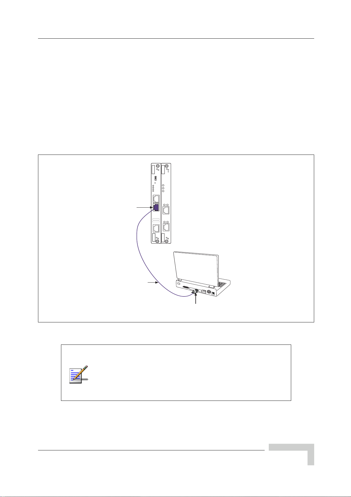
Off-Line Commissioning of the Micro BTS
3.2.3 Setting Up a Serial Connection via the ICP Processor Card Serial Port
1 Connect one end of the RJ-11 patch cable to ICP processor card connector
labeled CON.
2 Connect the opposite end of the RJ-11 patch cable to the DB-9 adapter and
connect the DB-9 adapter to the serial port on the back of the Craft PC, as
shown in the Figure 3-2.
Figure 3-2 shows a physical serial port connection between the Craft PC and the
ICP processor card.
I2C
RST
PWR
PWR
ONLINE
ON/LINE
FLT
SCN
FLT
ENET
ALARMS
IIIIIIIIIIIIIIIIIIIIIIIII
S/N XXXXXX
IIIIIIIIIIIIIIIIIIIIIIIII
P/N XXXXXX
12
CON
PORT 0
ALARMS
12
Serial Port
PORT 1
RJ-11 Patch Cable
Craft PC
computer
RJ-11 to DB-9
Adapter
IW043301
Figure 3-2: Connecting the Craft PC to the ICP Serial Port
In order to establish a serial connection between the Craft PC
and the Micro BTS, there cannot be an existing telnet or rlogin
connection on the Micro BTS. In the case where a user using the
Craft PC tries to establish a connection locally and a user using
the OMC tries to establish a connection remotely, the remote
user has priority access to the Micro BTS over the local user.
UltraWAVE Micro BTS Installation and Commissioning Guide, Version B 73
Page 90

Chapter 3 - Off-Line Commissioning
The following section describes procedures performed using the
Craft PC. For more information pertaining to the use of the Craft
PC, please refer to the GSM Craft PC Guide
1 If not already done, connect the Craft PC to the Micro BTS as described in
Section 3.2.3, and start XWindows on the Craft PC as described in
Section 3.2.1.
2 There are two methods to open a serial connection. You can use Hyper
Terminal or open the serial session in the Craft PC environment.
To use Hyper Terminal:
A Launch the application by navigating: Start -> Programs ->
Accessories -> Communications ->
B Enter CraftPC for the connection name and select an icon. Then click the
OK button.
.
Hyper Terminal
C The Connect To dialog box displays. You select
COM1 from the Connect
using drop-down list and click the OK button. If you know that your serial
port is configured on a different port, select that port from this drop-down
list.
D The COM1 Properties dialog box displays. Set the following properties and
then click the OK button. See Figure 3-3.
Bits per second: 9600
Data bits: 8
Parity: None
Stop bits: 1
Flow control: None
74 UltraWAVE Micro BTS Installation and Commissioning Guide, Version B
Page 91

Off-Line Commissioning of the Micro BTS
Figure 3-3: Serial Session Properties
E Select OK to connect to the processor card. At this time, you will not see a
prompt. Proceed to Section 3.2.4 to power on the chassis.
If you do not have the Hyper Terminal application, you can open a serial
session in the Craft PC application. In an Xterm window, type:
build@craftpc:~> cu -l ttyS0 [ENTER]
Connected.
UltraWAVE Micro BTS Installation and Commissioning Guide, Version B 75
Page 92

Chapter 3 - Off-Line Commissioning
3.2.4 Power-On LED Tests
This section describes how to power-on the Micro BTS and verify that the cards in
the system come up properly by viewing the Light Emitting Diodes (LEDs) on the
front panel. The purpose of these tests is to verify that the LEDs come up in the
correct state, indicating that the system is operating normally.
When you power-on the Micro BTS, it automatically runs its power on self tests
(POST), downloads software to the E1 or T1 cards, and then attempts to bring up
the cards. While it is bringing up the cards and when it is finished, the LEDs
indicate the state of each card.
Use the following procedure to power on the chassis and verify the LEDs:
1 Turn the power to the chassis on by simultaneously switching on two power
supplies. The power supply switches are shown in Figure 2-13 and
Figure 2-16. This will share the start up load across the power supplies.
2 Verify that the front-panel LEDs flash in the sequence shown in Figure 3-4.
76 UltraWAVE Micro BTS Installation and Commissioning Guide, Version B
Page 93

PWR
ONLINE
FLT
SCN
ENET
CON
IIIIIIIIIIIIIIIIIIIIIIIII
P/N XXXXXX
IIIIIIIIIIIIIIIIIIIIIIIII
S/N XXXXXX
I2C
IIIIIIIIIIIIIIIIIIIIIIIII
P/N XXXXXX
PWR
ON
LINE
FLT
120 OHM
ALARMS
12
PORT 0
ALARMS
12
PORT 1
TX
OUT
13 MHZ
CLK
RX-A
DET
IN
PWR
ON LINE
FLT
RX-B
Off-Line Commissioning of the Micro BTS
Power on BTS. Initial LED display is:
N/A
N/A
ICP E1/T1LEDs
ON
OFF
ON
OFF
N/A
ON
ON
ON
ON
ON
PWR
ON LINE
FLT
SCN
PORT 0
PORT 1
LED display after 50 seconds is:
N/A
N/A
ICP E1/T1LEDs
ON
OFF
OFF
OFF
N/A
ON
ON
ON
ON
ON
PWR
ON LINE
FLT
SCN
PORT 0
PORT 1
ICP code loads. LED display during download at 1:20:
PWR
ON LINE
FLT
SCN
PORT 0
PORT 1
N/A
N/A
ICP E1/T1LEDs
ON
ON
OFF
OFF
N/A
ON
ON
ON
ON
ON
ICP downloads code to E1 or T1 card. LED display
(at 2:45) during download is:
N/A
N/A
ICP E1/T1LEDs
ON
ON
ON
OFF
N/A
ON
ON
FLASH
FLASH
FLASH
PWR
ON LINE
FLT
SCN
PORT 0
PORT 1
TRX
N/A
N/A
N/A
TRX
N/A
N/A
N/A
TRX
N/A
N/A
N/A
TRX
N/A
N/A
N/A
ON
FLASH
OFF
ON
FLASH
OFF
ON
FLASH
OFF
ON
FLASH
OFF
IIIIIIIIIIIIIIIIIIIIIIIII
S/N XXXXXX
ICP E1/T1 TRX
Figure 3-4: LED Sequence During the Boot Process
PWR
ON LINE
FLT
SCN
PORT 0
PORT 1
Final LED display at 3 minutes is:
ICP E1/T1LEDs
N/A
N/A
ON
ON
ON
OFF
N/A
ON
ON
OFF
OFF
OFF
TRX
N/A
N/A
N/A
ON
FLASH
OFF
IW022303
UltraWAVE Micro BTS Installation and Commissioning Guide, Version B 77
Page 94

Chapter 3 - Off-Line Commissioning
3 When the sequence is completed, verify that the LEDs appear as shown in
Table 3-1.
Table 3-1: Normal LED Indications
LED Description
SCN Green LED, lit when processor card is operational.
Green LED, lit when card has power supplied.
PWR
ON LINE
FLT
The PWR LED of the ICP and E1 or T1 cards will be lit after all cards have
completed the boot-up process.
Green LED, lit when card is on-line, and card BOOT process has been
performed successfully.
The On-LINE LED of the ICP and E1 or T1 cards will be lit after all cards
have completed the boot-up process.
The TRX cards will not go on-line until they are unlocked by the OMC
operator.
Red LED, lit when card detects a fault or is not downloaded.
FLT LEDs will be lit on the TRX cards until their code is downloaded.
4 If your LEDs appear as described above, you have completed the LED power
up tests.
5 If your LEDs do not appear as described above, you can either:
Refer to the GSM Field Maintenance Guide
for troubleshooting procedures
Contact Customer Service
For more information about these unsuccessful power-up cases
and corrective actions to be taken upon unsuccessful power up,
refer to the GSM Field Maintenance Guide
.
6 You can monitor the status of the boot process using the serial session opened
in Section 3.2.3.
Once the LEDs on the processor cards have reached their final online status,
press the [ENTER] key. The prompt now changes to the following:
bts->
78 UltraWAVE Micro BTS Installation and Commissioning Guide, Version B
Page 95

Off-Line Commissioning of the Micro BTS
3.2.5 Configuring Boot Parameters
In this section, you verify the boot parameters and change them if necessary.
There are two reasons to change boot parameters:
If they are configured incorrectly, you must set them to the values shown here.
If your system is connected to the Ethernet, you must set the IP address to
support the Craft PC IP address 172.16.80.43. To make a connection with the
Craft PC, set the processor card IP address to 172.16.80.42:fffff000.
After changing the boot parameters, the Micro BTS must be rebooted before the
changes take effect.
1 If not already done, establish serial communications with the Micro BTS as
described in Section 3.2.3. If the Micro BTS starts rebooting endlessly, refer to
the GSM Craft PC Guide
normally, type:
bts-> bootChange [ENTER]
for corrective measures. If the Micro BTS boots
2 A list of boot parameters appears. Edit the parameter values using the
commands in Table 3-2.
Table 3-2: Changing Boot Parameters
Command Action
[ENTER]
. [ENTER]
- [ENTER] Returns to the previous parameter.
[CTRL][d] Aborts all changes and reverts to the current values.
Figure 3-5 shows the default bootChange parameters for the ICP processor card.
Accepts the current parameter value and proceeds to the next
parameter.
Erases the current parameter value and proceeds to the next
parameter.
UltraWAVE Micro BTS Installation and Commissioning Guide, Version B 79
Page 96

Chapter 3 - Off-Line Commissioning
'.' = clear field; '-' = go to previous field; ^D = quit
boot device : motfcc
processor number : 0
host name : craftpc
file name : /home/target/vxWorks
inet on ethernet (e) : 172.16.80.42:fffff000
inet on backplane (b):
host inet (h) : 172.16.80.43
gateway inet (g) :
user (u) : target
ftp password (pw) (blank = use rsh):
flags (f) : 0x0
target name (tn) : bts
startup script (s) : /home/target/bsxstart.ppc
other (o) : motfcc
value = 0 = 0x0
bts->
Figure 3-5: Boot Parameters for ICP Processor Card
You must edit the boot parameters to contain EXACT values, or
the equipment will not bootup properly.
3 For the new parameters to take effect, reboot the Micro BTS by pressing the
key combination [CTRL][x].
80 UltraWAVE Micro BTS Installation and Commissioning Guide, Version B
Page 97

Off-Line Commissioning of the Micro BTS
3.2.6 Setting Up an Ethernet Connection to the ICP Processor Card Ethernet Port
1 Connect the Ethernet crossover cable to the ICP processor card Ethernet port
labeled ENET.
2 Connect the other end of the cable to the Ethernet port on the Craft PC.
Figure 3-6 shows a typical Ethernet port connection between the Craft PC and the
ICP processor card.
Craft PC
PCMCIA Card Slot
or
Ethernet Port
RJ-45 Ethernet
Crossover cable
Ethernet
Port
RST
PWR
ONLINE
FLT
SCN
ENET
CON
IIIIIIIIIIIIIIIIIIIIIIIII
S/N XXXXXX
IIIIIIIIIIIIIIIIIIIIIIIII
P/N XXXXXX
PWR
ON/LINE
FLT
ALARMS
12
PORT 0
ALARMS
12
PORT 1
IE069401
Figure 3-6: Connection to the Craft PC via the ICP Ethernet Port
3.2.7 Verifying Telnet Communications with the Micro BTS over Ethernet
The Craft PC uses telnet communications across the Ethernet connection for code
downloads. Before performing any of the following procedures, ensure that you
can establish and terminate a telnet communications session as described in the
following procedures.
For more information about the Craft PC, please refer to the GSM
Craft PC Guide.
UltraWAVE Micro BTS Installation and Commissioning Guide, Version B 81
Page 98

Chapter 3 - Off-Line Commissioning
Establishing a Telnet Communications Session over Ethernet
1 Start a new Xterm window in the Craft PC environment.
2 Establish a telnet communications session by typing:
build@craftpc:-> telnet iwbox [ENTER]
If the Craft PC hangs when attempting to establish a telnet
session, press the key combination [CTRL][c] to abort the failed
connection. Check the boot parameters and repeat the
connection procedures. Also verify that the Craft PC host table
contains the hostname of your equipment in reference to the
default IP address.
3 The Craft PC prompt now changes to bts->. This prompt verifies that the
telnet session can be established. If this is not the case, verify the Ethernet
wiring and retry.
Terminating a Telnet Communications Session over Ethernet
After verifying that a telnet communications session can be established, terminate
the telnet session as follows.
Once a telnet session has been established between the Craft PC
and the processor card, it must be terminated before the Craft PC
is powered off.
connection on the BSS system
1 Activate the Xterm window in which the telnet communications session was
established.
2 To terminate the telnet session, type in the Xterm window containing the
telnet session:
bts-> logout [ENTER]
3 The return message should read Connection closed by foreign host and
the prompt changes back to build@craftpc->. The telnet session has now
been terminated.
Failure to do this will result in a hung
.
82 UltraWAVE Micro BTS Installation and Commissioning Guide, Version B
Page 99

Software Verification using Craft PC
3.3 Software Verification using Craft PC
In this section, you use the Craft PC to verify the software configuration and other
aspects of the Micro BTS operation. It is assumed that you have:
Made the physical Craft PC connections to the processor card
An active serial session
3.3.1 Verifying the Current Software Version and Patch Level
The following section describes procedures performed using the
Craft PC. For more information about the Craft PC, refer to the
GSM Craft PC Guide
.
1 If not already done, establish serial communications with the Micro BTS as
described in Section 3.2.3.
2 After the bts-> prompt appears, verify the current software version and patch
level by typing:
bts-> iwversion [ENTER]
BTS code version: iw07_00.ZZZ
Release number: 7.0
ABIS version: 1.1
Packages Installed:
Encryption: A5/1
Patches Installed:
patch<#> <file directory> <patch size> <iw07_00.ZZZ>
The current software version is displayed, represented above by the parameter
iw07_00.ZZZ. This number should correspond to the software version detailed
in the release notes included with the CD-ROM. Keep this number for your
records.
3 Verify under Patches Installed: that the most current patch is installed, if
applicable. Refer to the GSM Craft PC Guide
patches. If you are unsure if you require software patches, contact your
Level 2 support representative for additional assistance.
for procedures to install required
UltraWAVE Micro BTS Installation and Commissioning Guide, Version B 83
Page 100

Chapter 3 - Off-Line Commissioning
If the displayed software version number does not coincide with
the software version being run on the network for which this
Micro BTS is going to be used, refer to Section 3.4 for
instructions on how to install a different software version on the
processor card.
3.3.2 Checking the Flash Version Number
In order to verify that the correct software build is loaded into flash memory, go to
your serial Xterm window and type:
bts-> printConfigBlocks [ENTER]
The screen displays information relating to the flash images. Figure 3-7 shows
Image 0, Image 1 and Image 2 from the ICP card configuration.
**** Current Image = 1 ****
******** Image 0 *********
Image IW version : iw07_00.010
Image creation date: 04/15/02 13:44
Image crc : 1ff03d8d
******** Image 1 *********
Image IW version : iw7_00.012
Image creation date: 04/09/02 12:07
Image crc : e3b05e8c
******** Image 2 *********
Image IW version : iw07_00.010
Image creation date: 04/09/02 12:07
Image crc : e3b05e8c
Figure 3-7: Determining the Flash Version on an ICP Processor Card
The ICP configuration states Current Image = N where N is either 0 or 1. The
flash version have lines in the format:
iw07_00.ZZZ
where iw07_00.ZZZ indicates the flash version.
84 UltraWAVE Micro BTS Installation and Commissioning Guide, Version B
 Loading...