

Page 1
AD-75V
Gas/Electric/Steam (DSI/Phase 7 Non-Coin/S.A.F.E.)
Installation Manual
W ARNING: For your safety the information in
this manual must be followed to minimize the
risk of fire or explosion or to prevent property
damage, personal injury or death.
— Do not store or use gasoline or other flammable
vapors and liquids in the vicinity of this or any
other appliance.
— WHA T TO DO IF YOU SMELL GAS:
• Do not try to light any appliance.
• Do not touch any electrical switch; do not
use any phone in your building.
• Clear the room, building or area of all
occupants.
• Immediately call your gas supplier from a
neighbor’s phone. Follow the gas supplier’s
instructions.
• If you cannot reach your gas supplier, call
the fire department.
— Installation and service must be performed by a
qualified installer, service agency or the gas
supplier.
AVERTISSEMENT: Assurez-vous de bien
suivre les instructions données dans cette notice
pour réduire au minimum le risque d’incendie
ou d’explosion ou pour éviter tout dommage
matériel, toute blessure ou la mort.
— Ne pas entreposer ni utiliser d’essence ni
d’autres vapeurs ou liquides inflammables à
proximité de cet appareil ou de tout autre
appareil.
— QUE F AIRE SI VOUS SENTEZ UNE ODEUR
DE GAZ:
• Ne pas tenter d’allumer d’appareils.
• Ne touchez à aucun interrupteur . Ne pas
vous servir des téléphones se trouvant dans
le bâtiment.
• Évacuez la pièce, le bâtiment ou la zone.
• Appelez immédiatement votre fournisseur
de gaz depuis un voisin. Suivez les
instructions du fournisseur.
• Si vous ne pouvez rejoindre le fournisseur
de gaz, appelez le service des incendies.
— L ’installation et l’entretien doivent être assurés par
un installateur ou un service d’entretien qualifié
ou par le fournisseur de gaz.
For replacement parts, contact the reseller from which the dryer
was purchased or
American Dryer Corporation
88 Currant Road
Fall River MA 02720-4781 USA
T elephone: (508) 678-9000 / Fax: (508) 678-9447
e-mail: techsupport@amdry .com
www.amdry.com
080602JEV/mcronan ADC Part No. 113381
Page 2

Retain This Manual In A Safe Place For Future Reference
American Dryer Corporation products embody advanced concepts in engineering, design, and safety. If this product is
properly maintained, it will provide many years of safe, efficient, and trouble free operation.
ONLY qualified technicians should service this equipment.
OBSERVE ALL SAFETY PRECAUTIONS displayed on the equipment or specified in the installation manual included with
the dryer.
The following “FOR YOUR SAFETY” caution must be posted near the dryer in a prominent location.
FOR YOUR SAFETY
Do not store or use gasoline or
other flammable vapors and
liquids in the vicinity of this or
any other appliance.
W e have tried to make this manual as complete as possible and hope you will find it useful. ADC reserves the right to make
changes from time to time, without notice or obligation, in prices, specifications, colors, and material, and to change or
discontinue models. The illustrations included in this manual may not depict your particular dryer exactly.
POUR VOTRE SÉCURITÉ
Ne pas entreposer ni utiliser d’essence
ni d’autres vapeurs ou liquides
inflammables à proximité de cet
appareil ou de tout autre appareil.
Important
For your convenience, log the following information:
DA TE OF PURCHASE________________________________ MODEL NO. __________________________________________
RESELLER’S NAME ________________________________________________________________________________________
Serial Number(s) ________________________________________________________________________________________
AD-75V Phase 7
________________________________________________________________________________________
________________________________________________________________________________________
Replacement parts can be obtained from your reseller or the ADC factory. When ordering replacement parts from the factory ,
you can F AX your order to ADC at (508) 678-9447 or telephone your order directly to the ADC Parts Department at (508)
678-9000. Please specify the dryer model number and serial number in addition to the description and part number, so that
your order is processed accurately and promptly.
“IMPORT ANT NOTE TO PURCHASER”
Information must be obtained from your local gas supplier on the instructions
to be followed if the user smells gas. These instructions must be posted in a
prominent location near the dryer.
Page 3
IMPORTANT
YOU MUST DISCONNECT AND LOCKOUT THE ELECTRIC SUPPL Y AND THE GAS
SUPPLY OR THE STEAM SUPPLY BEFORE ANY COVERS OR GUARDS ARE
REMOVED FROM THE MACHINE TO ALLOW ACCESS FOR CLEANING,
ADJUSTING, INSTALLATION, OR TESTING OF ANY EQUIPMENT PER OSHA
(Occupational Safety and Health Administration) ST ANDARDS.
«Attention: Au moment de l’entretien des
“Caution: Label all wires prior to
disconnection when servicing controls. W iring
errors can cause improper operation.”
commandes, étiquetez tous les fils avant de
les débrancher. Des erreurs de câblage
peuvent entraîner un fonctionnement
inadéquat et dangereux.»
CAUTION
DR YERS SHOULD NEVER BE LEFT UNA TTENDED WHILE IN OPERA TION.
WARNING
CHILDREN SHOULD NOT BE ALLOWED TO PLA Y ON OR NEAR THE DRYER(S).
CHILDREN
SHOULD BE SUPER VISED IF NEAR DR YERS IN OPERATION.
FOR YOUR SAFETY
DO NOT DR Y MOP HEADS IN THE DRYER.
DO NOT USE DR YER IN THE PRESENCE OF DR Y CLEANING FUMES.
WARNING
UNDER NO CIRCUMSTANCES should the dryer door switches, lint drawer switch or
the heat safety circuit ever be disabled.
Page 4
WARNING
The dryer must never be operated with any of the back guards, outer tops, or service
panels removed. PERSONAL INJURY OR FIRE COULD RESUL T .
WARNING
DRYER MUST NEVER BE OPERA TED WITHOUT THE LINT FIL TER/SCREEN IN
PLACE, EVEN IF AN EXTERNAL LINT COLLECTION SYSTEM IS USED.
IMPORTANT
PLEASE OBSERVE ALL SAFETY PRECAUTIONS displayed on the equipment and/or
specified in the installation manual included with the dryer.
Dryer must not be installed or stored in an area where it will be exposed to water or weather .
The wiring diagram for the dryer is located in the front electrical control box area.
IMPORTANT
Dryer must be installed in a location/environment, which the ambient temperature
remains between 40° F (4.44° C) and 130° F (54.44° C).
Page 5

Table of Contents
SECTION I
IMPORTANT INFORMATION ............................................................................... 3
A. Receiving and Handling ............................................................................................................... 3
B. Safety Precautions ...................................................................................................................... 4
SECTION II
SPECIFICATIONS/COMPONENT IDENTIFICATION .....................................6
A. Specifications ............................................................................................................................. 6
B. Component Identification ............................................................................................................ 8
SECTION III
INSTALLATION PROCEDURES .........................................................................1 0
A. Location Requirements ............................................................................................................. 10
B. Unpacking/Setting Up ............................................................................................................... 11
C. Dryer Enclosure Requirements .................................................................................................. 12
D. Fresh Air Supply Requirements ................................................................................................. 13
E. Exhaust Requirements ............................................................................................................... 14
F. Electrical Information ................................................................................................................ 19
G . Gas Information ........................................................................................................................ 24
H. Steam Information .................................................................................................................... 28
I. Preparation For Operation/Start-Up ......................................................................................... 32
J. Preoperational T ests ................................................................................................................. 33
K. Preoperational Instructions ........................................................................................................ 35
L. Shutdown Instructions............................................................................................................... 36
SECTION IV
SERVICE/PARTS INFORMATION ...................................................................... 3 7
A. Service ..................................................................................................................................... 37
B. Parts ........................................................................................................................................ 37
SECTION V
WARRANTY INFORMATION ............................................................................... 38
A. Returning W arranty Cards......................................................................................................... 38
B. Warranty .................................................................................................................................. 38
C. Returning Warranty Parts .......................................................................................................... 38
SECTION VI
ROUTINE MAINTENANCE ..................................................................................4 0
A. Cleaning ................................................................................................................................... 40
B. Adjustments ............................................................................................................................. 41
C. Lubrication ............................................................................................................................... 42
Page 6

SECTION VII
PROCEDURE FOR FUNCTIONAL CHECK OF REPLACEMENT
COMPONENTS........................................................................................................43
SECTION VIII
REVERSING TIMER SPIN/DWELL ADJUSTMENTS ..................................... 45
SECTION IX
DATA LABEL INFORMATION ............................................................................. 4 6
A. Data Label ............................................................................................................................... 46
SECTION X
SENSOR ACTIVATED FIRE EXTINGUISHING (S.A.F.E.) SYSTEM ........... 4 8
Installation ...................................................................................................................................... 49
Sensor Activated Fire Extinguishing (S.A.F.E.) System Theory of Operation .................................... 52
System Reset.................................................................................................................................. 52
Non-Coin S.A.F .E. System Check Procedure................................................................................. 52
Sensor Activated Fire Extinguishing (S.A.F .E.) System Parts Break Down ....................................... 53
Page 7

SECTION I
IMPORTANT INFORMA TION
A. RECEIVING AND HANDLING
The dryer is shipped in a protective stretch wrap cover with protective cardboard corners and top cover (or
optional box) as a means of preventing damage in transit. Upon delivery, the dryer and/or packaging, and
wooden skid should be visually inspected for shipping damage. If any damage whatsoever is noticed, inspect
further before delivering carrier leaves.
Dryers damaged in shipment:
1.
ALL dryers should be inspected upon receipt and before they are signed for.
2. If there is suspected damage or actual damage, the trucker ’s receipt should be so noted.
3. If the dryer is damaged beyond repair, it should be refused. Those dryers which were not damaged in a
damaged shipment should be accepted, but the number received and the number refused must be noted
on the receipt.
4. If you determine that the dryer was damaged after the trucker has left your location, you should call the
delivering carrier’s freight terminal immediately and file a claim. The freight company considers this
concealed damage. This type of freight claim is very difficult to get paid and becomes extremely difficult
when more than a day or two passes after the freight was delivered. It is your responsibility to file freight
claims. Dryer/parts damaged in transit cannot be claimed under warranty.
5. Freight claims are the responsibility of the consignee, and ALL claims must be filed at the receiving end.
ADC assumes no responsibility for freight claims or damages.
6. If you need assistance in handling the situation, please contact the ADC Traffic Manager at (508)
678-9000.
IMPORTANT: The basket (tumbler) section of the dryer must be transported and handled in an
upright position at ALL times.
3
Page 8
B. SAFETY PRECAUTIONS
WARNING: For your safety , the information in this manual must be followed to minimize the risk of
fire or explosion or to prevent property damage, personal injury , or loss of life.
WARNING: The dryer must never be operated with any of the back guards, outer tops, or
service panels removed. PERSONAL INJURY OR FIRE COULD RESUL T.
1. DO NOT store or use gasoline or other flammable vapors and liquids in the vicinity of this or any other
appliance.
2. Purchaser/user should consult the local gas supplier for proper instructions to be followed in the event the
user smells gas. The instructions should be posted in a prominent location.
3. WHAT TO DO IF YOU SMELL GAS...
a. DO NOT try to light any appliance.
b. DO NOT touch any electrical switch.
c. DO NOT use any phone in your building.
d. Clear the room, building, or area of ALL occupants.
e. Immediately call your gas supplier from a neighbor’ s phone. Follow the gas supplier’s instructions.
f. If you cannot reach your gas supplier, call the fire department.
4. Installation and service must be performed by a qualified installer, service agency , or gas supplier.
5. Dryer(s) must be exhausted to the outdoors.
6. Although ADC produces a very versatile dryer, there are some articles that, due to fabric composition or
cleaning method, should not be dried in it.
WARNING: Dry only water washed fabrics. DO NOT dry articles spotted or washed in dry
cleaning solvents, a combustible detergent, or “all purpose” cleaner .
EXPLOSION COULD RESUL T.
WARNING: DO NOT dry rags or articles coated or contaminated with gasoline, kerosene, oil, paint,
or wax.
EXPLOSION COULD RESUL T.
WARNING: DO NOT dry mop heads. Contamination by wax or flammable solvents will create a
fire hazard.
WARNING: DO NOT use heat for drying articles that contain plastic, foam, sponge rubber , or
similarly textured rubber materials. Drying in a heated basket (tumbler) may damage
plastics or rubber and may be a fire hazard.
4
Page 9
7. A program should be established for the inspection and cleaning of lint in the heating unit area, exhaust
ductwork, and inside the dryer. The frequency of inspection and cleaning can best be determined from
experience at each location.
WARNING: The collection of lint in the burner area and exhaust ductwork can create a potential fire
hazard.
8. For personal safety, the dryer must be electrically grounded in accordance with local codes and/or the
National Electrical Code ANSI/NFPA NO. 70-LATEST EDITION or in Canada, the Canadian Electrical
Codes Parts 1 & 2 CSA C22.1-1990 or LATEST EDITION.
NOTE: Failure to do so will VOID THE WARRANTY.
9. UNDER NO CIRCUMSTANCES should the dryer door switches, lint drawer switch, or the heat safety
circuit ever be disabled.
W ARNING: PERSONAL INJURY OR FIRE COULD RESUL T.
10. This dryer is not to be used in the presence of dry cleaning solvents or fumes.
11. Remove articles from the dryer as soon as the drying cycle has been completed.
WARNING: Articles left in the dryer after the drying and cooling cycles have been completed can
create a fire hazard.
12. DO NOT operate steam dryers with more than 125 psi (8.62 bar) steam pressure. Excessive steam
pressure can damage steam coil and/or harm personnel.
13. Replace leaking flexible hoses or other steam fixtures immediately. DO NOT operate the dryer with
leaking flexible hoses. PERSONAL INJURY MAY RESULT.
14. The normal PH level for copper type steam coils must be maintained between a value of 8.5 to 9.5. For
steel type steam coils the PH level must be maintained between a value of 9.5 to 10.5. These limits are set
to limit the acid attack of the steam coils.
IMPORTANT: Coil failure due to improper PH level will VOID THE WARRANTY .
15. READ AND FOLLOW ALL CAUTION AND DIRECTION LABELS ATTACHED TO THE
DRYER.
16. For safety, proper operation, and optimum performance, the dryer must not be operated with a load less
than sixty-six percent (66%), 50 lbs (22.67 kg) of its rated capacity .
W ARNING: YOU MUST DISCONNECT AND LOCKOUT THE ELECTRIC SUPPL Y AND
THE GAS SUPPL Y OR THE STEAM SUPPL Y BEFORE ANY COVERS OR
GUARDS ARE REMOVED FROM THE MACHINE TO ALLOW ACCESS
FOR CLEANING , ADJUSTING, INST ALLA TION, OR TESTING OF ANY
EQUIPMENT PER OSHA (Occupational Safety and Health Administration)
STANDARDS.
IMPORTANT: Dryer must be installed in a location/environment, which the ambient
temperature remains between 40° F (4.44° C) and 130° F (54.44° C).
5
Page 10
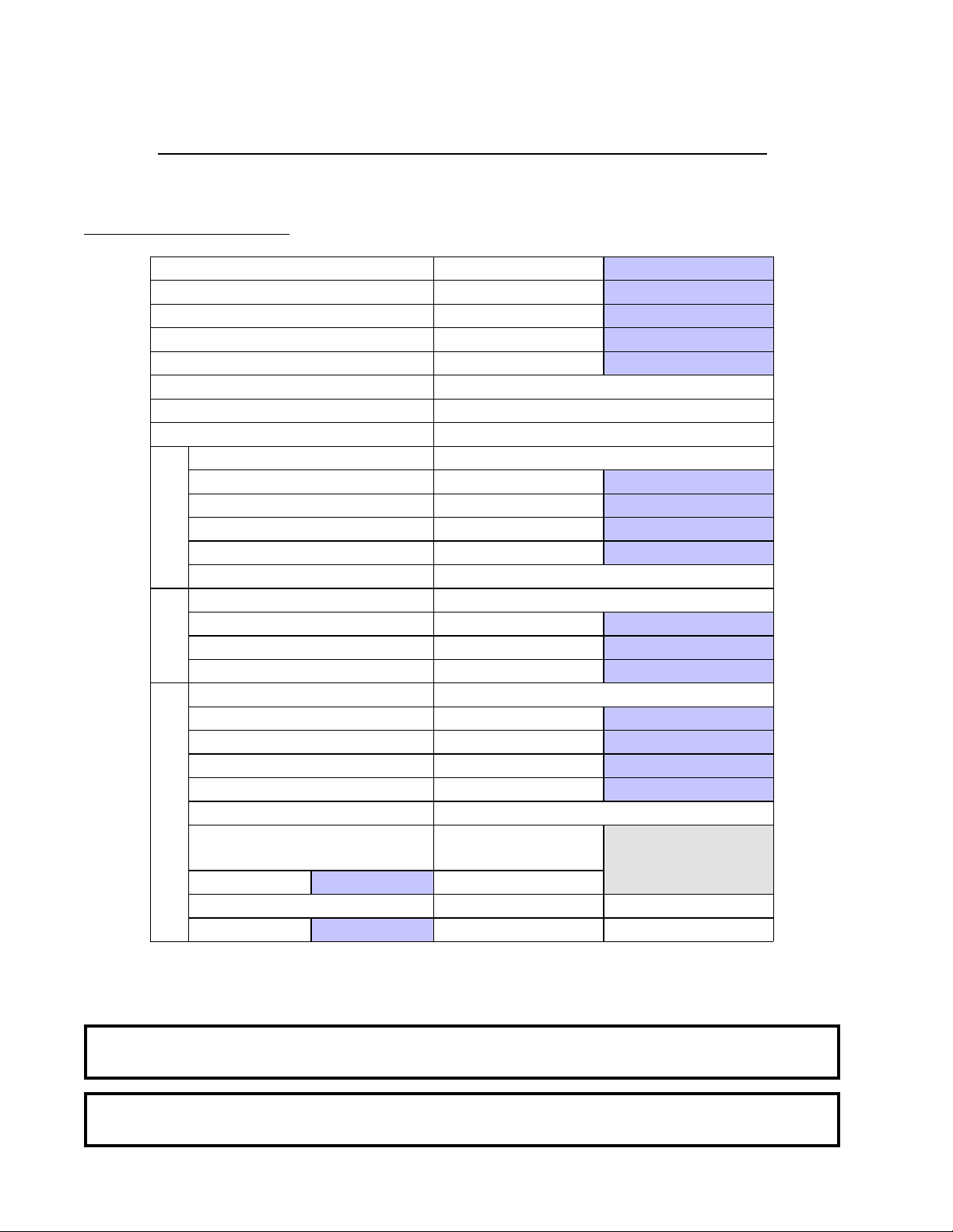
SPECIFICATIONS/COMPONENT IDENTIFICATION
A. SPECIFICATIONS
SECTION II
BASKET (TUMBLER) DIAMETER 37”
BASKET (TUMBLER) DEPTH 36”
BASKET (TUMBLER) MOTOR 1 hp*
DOOR OPENING (DIAMETER) 21-1/2”
BASKET (TUMBLER) VOLUME 22.4 cu ft
DRYERS PER 20’ /40’ CONTAINER 10 /20
DRYERS PER 45’/48’ TRUCK 24/24
S.A.F.E. WATER CONNECTION 3/4-11.5 NH
VOLTAGE AVAILABLE 120-460v 1ø-3ø 50/60 Hz
APPROX. WEIGHT (UNCRATED) 721 lbs
APPROX. WEIGHT (CRATED ) 771 lbs
HEAT INPUT 200,000 btu/hr
Gas
AIRFLOW 900 cfm
INLET PIPE SIZE 3/4” F.N.P.T.**
VOLTAGE AVAILABLE 208-460v 1ø-3ø 50/60 Hz
APPROX. WEIGHT (UNCRATED) 721 lbs
APPROX. WEIGHT (CRATED ) 771 lbs
AIRFLOW 1200 cfm
Electric
VOLTAGE AVAILABLE 120-460v 1ø-3ø 50/60 Hz
APPROX. WEIGHT (UNCRATED) 752 lbs
APPROX. WEIGHT (CRATED ) 802 lbs
AIRFLOW 1200 cfm
COMPRESSED AIR VOLUME 0.75 cfh
AIR CONNECTION 1/8” F.N.P.T.
Steam
Shaded areas are stated in metric equivalents 9/8/03
STEAM CONSUMPTION
238.7 lbs/hr
OPERATING STEAM PRESSURE STEAM SUPPLY STEAM RETURN
125 psi max
108.3 kg/hr
8.6 bar
BOILER HP
NORMAL LOAD
7
1” F.N.P.T. 1” F.N.P.T.
94 cm
91.5 cm
0.746 kw
54.6 cm
0.634 cu m
327 kg
349.7 kg
50,400 kcal/hr
25.44 cmm
327 kg
349.7 kg
25.44 cmm
341.1 kg
363.8 kg
25.44 cmm
0.02 cmh
* For non-reversing models.
** A minimum of 3/4” pipe must be supplied to the gas inlet for each dryer.
IMPORTANT: Steam dryers must be provided with clean, dry , and regulated 80 psi +/- 10 psi (5.51
bar +/- 0.69 bar) air supply .
NOTE: ADC reserves the right to make changes in specifications at any time without notice or
obligation.
6
Page 11
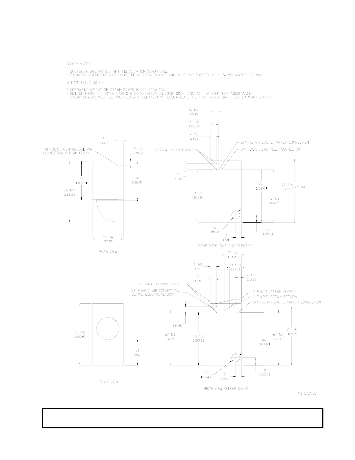
Specifications (Gas, Electric, and Steam)
NOTE: ADC reserves the right to make changes in specifications at any time without notice or
obligation.
7
Page 12
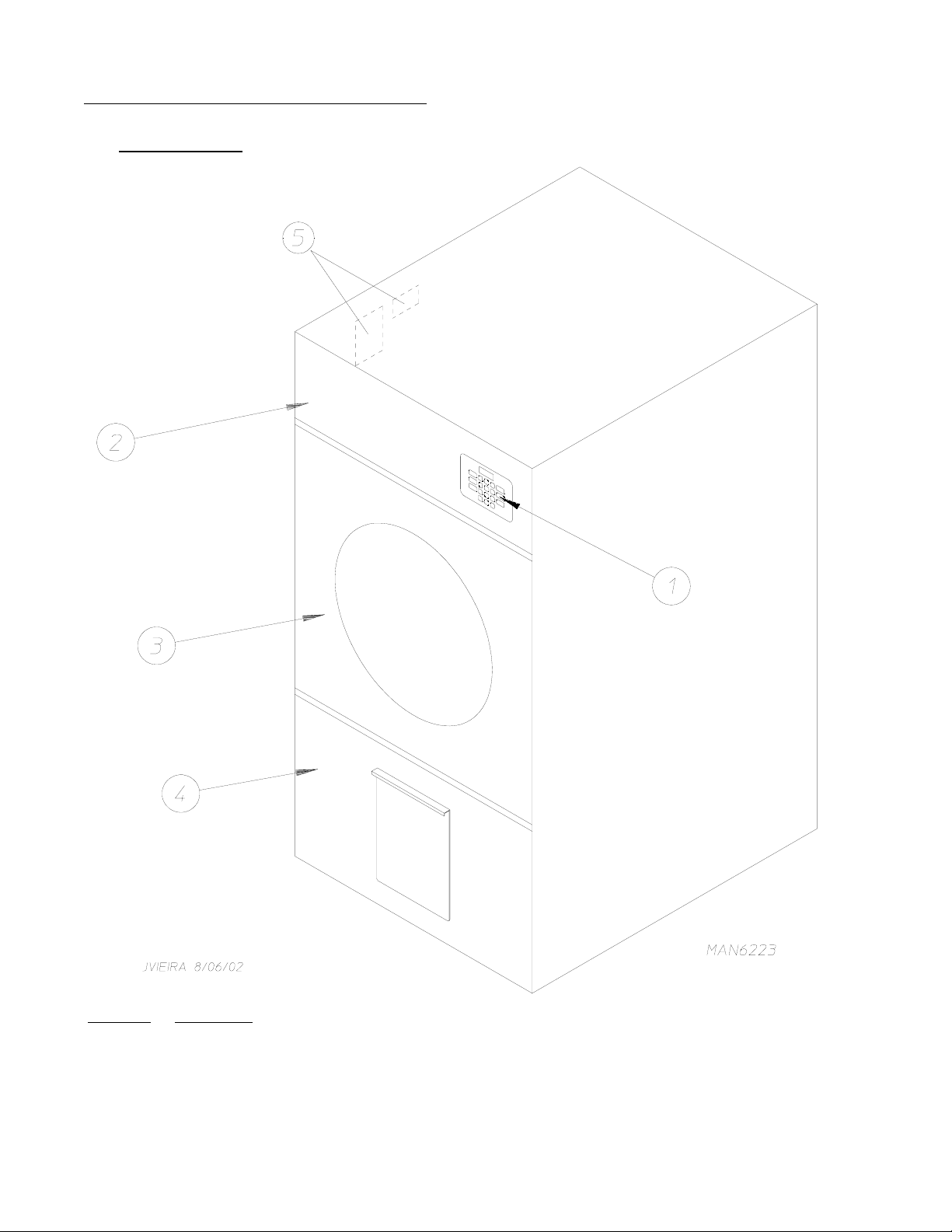
B. COMPONENT IDENTIFICATION
1. Dryer Front View
Illus. No. Description
1 Controls
2 Control (top access) Door Assembly
3 Main Door Assembly
4 Lint Compartment Drawer
5 Data Label and Installation Label
8
Page 13
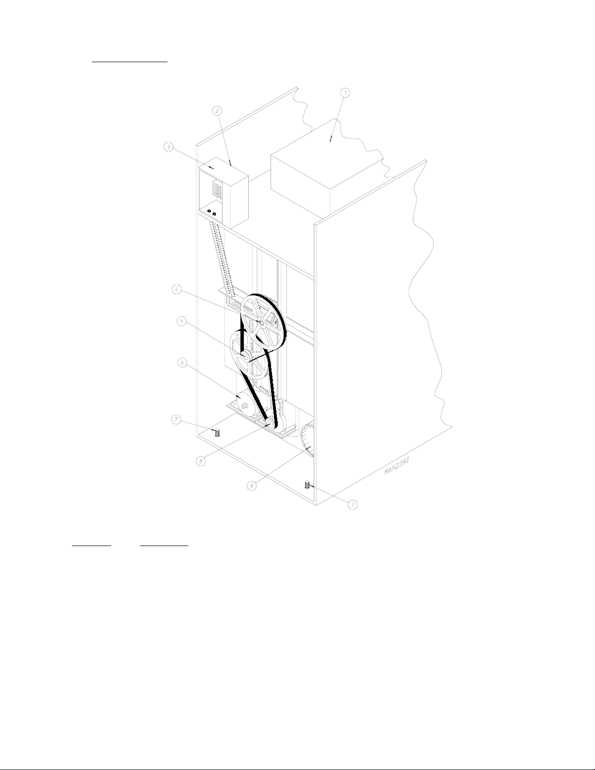
2. Dryer Rear View
Illus. No. Description
1 Heating Unit
2 1/8” Compressed Air Supply Inlet
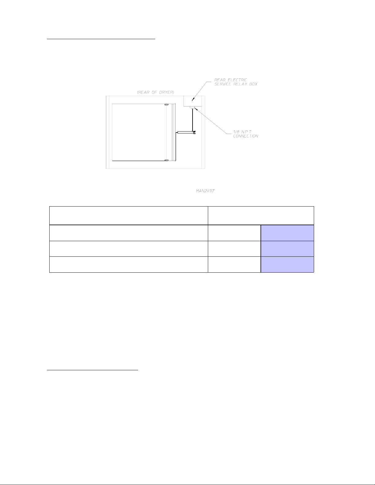
(NOTE: Behind electric service relay box for steam units Only)
3* Electric Service Relay Box
4 Basket (tumbler) Bearing Mount Assembly
5 Idler Bearing Mount Assembly
6 Blower Motor Assembly
7 Leveling Leg (rear)
8 Basket (tumbler) Drive Motor Assembly (reversing models Only)
9 Dryer Exhaust
* Electric service connections for gas and steam models are made in this box.
9
Page 14
SECTION III
INSTALLATION PROCEDURES
Installation should be performed by competent technicians in accordance with local and state codes. In the
absence of these codes, the installation must conform to applicable American National S tandards: ANSI Z223.1-
LATEST EDITION (National Fuel Gas Code) or ANSI/NFPA NO. 70-LATEST EDITION (National Electrical
Code) or in Canada, the installation must conform to applicable Canadian Standards: CAN/CGA-B149.1-M91
(Natural Gas) or CAN/CGA-B149.2-M91 (Liquid Propane [L.P.] Gas) or LATEST EDITION (for General
Installation and Gas Plumbing) or Canadian Electrical Codes Parts 1 & 2 CSA C22.1-1990 or LATEST EDITION
(for Electrical Connections).
A. LOCATION REQUIREMENTS
Before installing the dryer, be sure the location conforms to local codes and ordinances. In the absence of such
codes or ordinances the location must conform with the National Fuel Gas Code ANSI.Z223.1 LATEST
EDITION, or in Canada, the installation must conform to applicable Canadian Standards: CAN/CGA-B149.1M91 (Natural Gas) or CAN/CGA-B149.2-M91 (L.P. Gas) or LATEST EDITION (for General Installation and
Gas Plumbing).
1. The dryer must be installed on a sound level floor capable of supporting its weight. Carpeting must be
removed from the floor area that the dryer is to rest on.
IMPORTANT: “The dryer must be installed on noncombustible floors only .”
2. The dryer must not be installed or stored in an area where it will be exposed to water and/or weather.
3. The dryer is for use in noncombustible locations.
4. Provisions for adequate air supply must be provided as noted in this manual (refer to Fresh Air Supply
Requirements in
5. Clearance provisions must be made from combustible construction as noted in this manual (refer to Dryer
Enclosure Requirements in
6. Provisions must be made for adequate clearances for servicing and for operation as noted in this manual
(refer to Dryer Enclosure Requirements in
7. Dryer must be exhausted to the outdoors as noted in this manual (refer to Exhaust Requirements in
Section E).
8. Dryer must be located in an area where correct exhaust venting can be achieved as noted in this manual
(refer to Exhaust Requirements in
Section D).
Section C).
Section C).
Section E).
IMPORTANT: Dryer should be located where a minimum amount of exhaust duct will be necessary .
9. The dryer must be installed with a proper exhaust duct connection to the outside.
10. The dryer must be installed with provisions for adequate combustion and make-up air supply.
10
Page 15
CAUTION: This dryer produces combustible lint and must be exhausted to the outdoors. Every 6
months, inspect the exhaust ducting and remove any lint build up.
IMPORTANT: Dryer must be installed in a location/environment, which the ambient
temperature remains between 40° F (4.44° C) and 130° F (54.44° C).
B. UNPACKING/SETTING UP
Remove protective shipping material (i.e., plastic wrap, and/or optional shipping box) from dryer.
IMPORTANT: Dryer must be transported and handled in an upright position at ALL times.
The dryer can be moved to its final location while still attached to the skid or with the skid removed. T o unskid
the dryer, locate and remove the four (4) bolts securing the base of the dryer to the wooden skid. Two (2) are
at the rear base (remove the back panel for access), and two (2) are located in the bottom of the lint chamber.
T o remove the two (2) bolts located in the lint chamber area, remove the lint door.
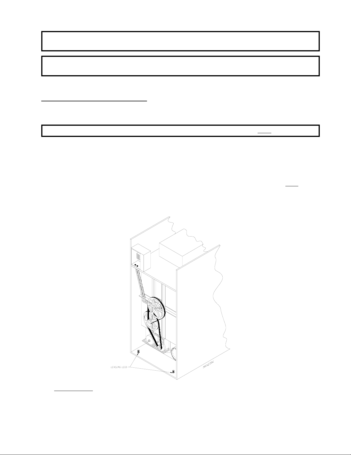
With the skid removed, to make it easier to slide the dryer into its final position, slightly lower ALL four (4)
leveling legs, so that the dryer will slide on the legs instead of the base frame.
T o increase bearing life and improve efficiency, the dryer should be tilted slightly to the rear.
1. Leveling Dryer
The dryer is equipped with four (4) leveling legs, one (1) at each corner of the base. Two (2) are located
at the rear of the dryer base, and two (2) are located in the lint chamber (coop). To increase bearing life
and improve efficiency, the dryer should be tilted slightly to the rear.
11
Page 16
C. DRYER ENCLOSURE REQUIREMENTS
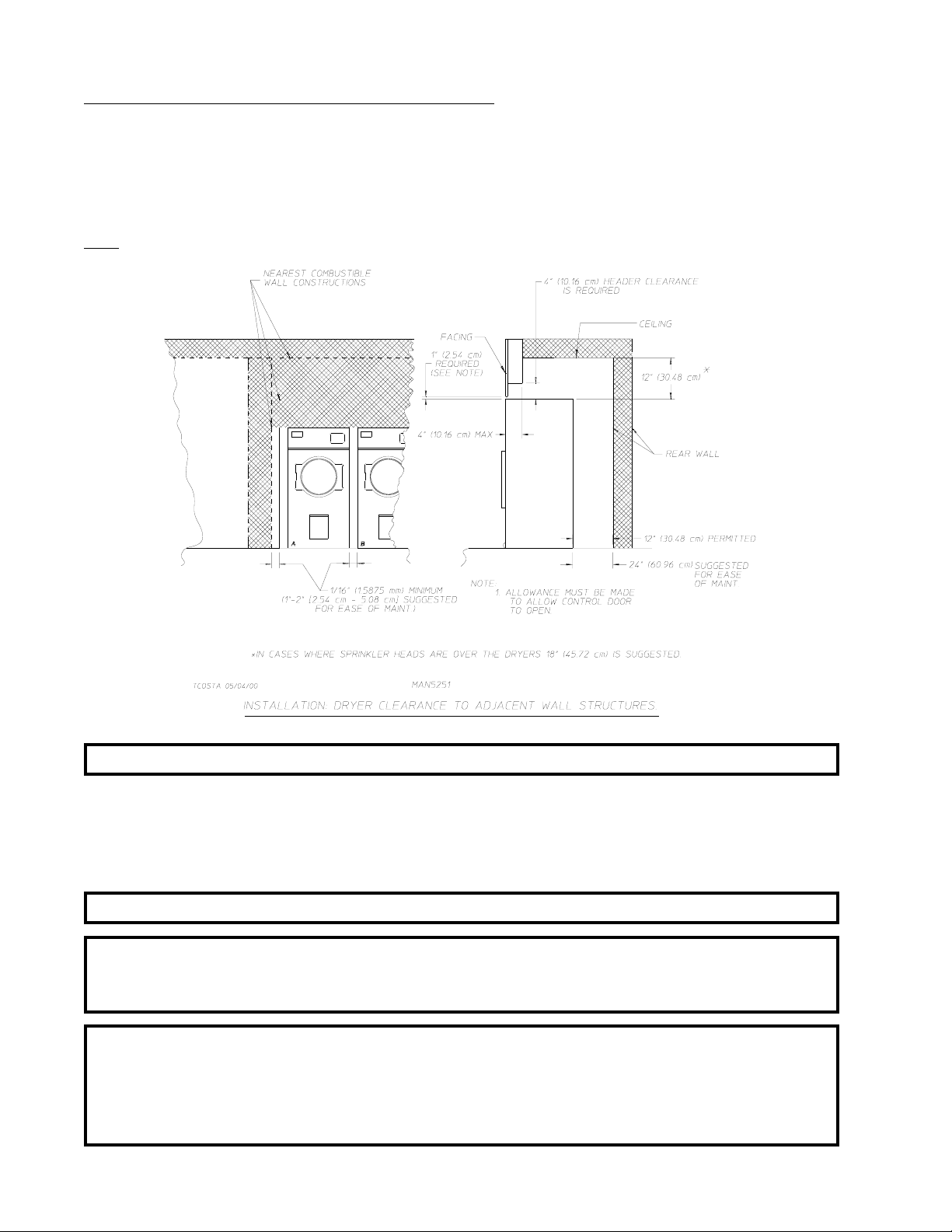
Bulkheads and partitions should be made of noncombustible materials and must be located a minimum of
12-inches (30.48 cm), 18-inches (45.72 cm) or more is recommended for ease of installation, maintenance, and
service above the dryer outer top, except along the front of the dryer which may be partially closed in if desired.
The clearance between the bulkhead header and the dryer must be a minimum of 4-inches (10.16 cm) and must
not extend more than 4-inches (10.16 cm) to the rear of the front. The bulkhead facing must not be closed in
ALL the way to the top of the dryer. A 1-inch (2.54 cm) clearance is required.
NOTE: Allowances must be made for opening the control door.
Dryers may be positioned sidewall to sidewall. However, a 1/16” (1.5875 mm) minimum allowance must be
made for the opening and closing of the control door and the lint door. It is suggested that the dryer be positioned
about 30-inches (76.2 cm) away from the nearest obstruction for ease of installation, maintenance, and service
(to be measured from the back guard.) Refer to the illustration above for details.
NOTE: Air considerations are important for proper and efficient operation.
IMPORTANT: For overhead clearance, even though a minimum of only 12-inches (30.48 cm) is
required, 18-inches (45.72 cm) or more is suggested. The additional clearance is
advantageous for ease of installation and service.
IMPORTANT: When fire sprinkler systems are located above the dryers, a minimum of 18-inches
(45.72 cm) above the dryer console (module) is required. Dryers may be positioned
sidewall to sidewall however, a 1/16” (1.5875 mm) minimum allowance is required
between dryers (or wall) for ease of installation and maintenance. Allowances must
be made for the opening and closing of the control door and the lint door .
12
Page 17
D. FRESH AIR SUPPLY REQUIREMENTS
When the dryer is operating, it draws in room air, heats it, passes this air through the basket (tumbler), and
exhausts it out of the building. Therefore, the room air must be continually replenished from the outdoors. If the
make-up air is inadequate, drying time and drying efficiency
sail switch “fluttering” problems may result, as well as premature motor failure from overheating.
Air supply (make-up air) must be given careful consideration to assure proper performance of each dryer. An
unrestricted source of air is necessary for each dryer. An airflow of 900 cfm (25.44 cmm) must be supplied to
gas dryers and 1,200 cfm (33.98 cmm) for electric or steam dryers. As a general rule, an unrestricted air
entrance from the outdoors (atmosphere) of a minimum of 1-1/2 square feet (0.14 square meters) is required for
each dryer.
will be adversely affected. Ignition problems and
T o compensate for the use of registers or louvers used over the openings, this make-up air must be increased by
approximately thirty-three percent (33%). Make-up air openings should not be located in an area directly near
where exhaust vents exit the building.
It
is not necessary to have a separate make-up air opening for each dryer. Common make-up air openings are
acceptable. However, they must be set up in such a manner that the make-up air is distributed equally to ALL
the dryers. The dryer must be installed with provisions for adequate combustion and make-up air supply.
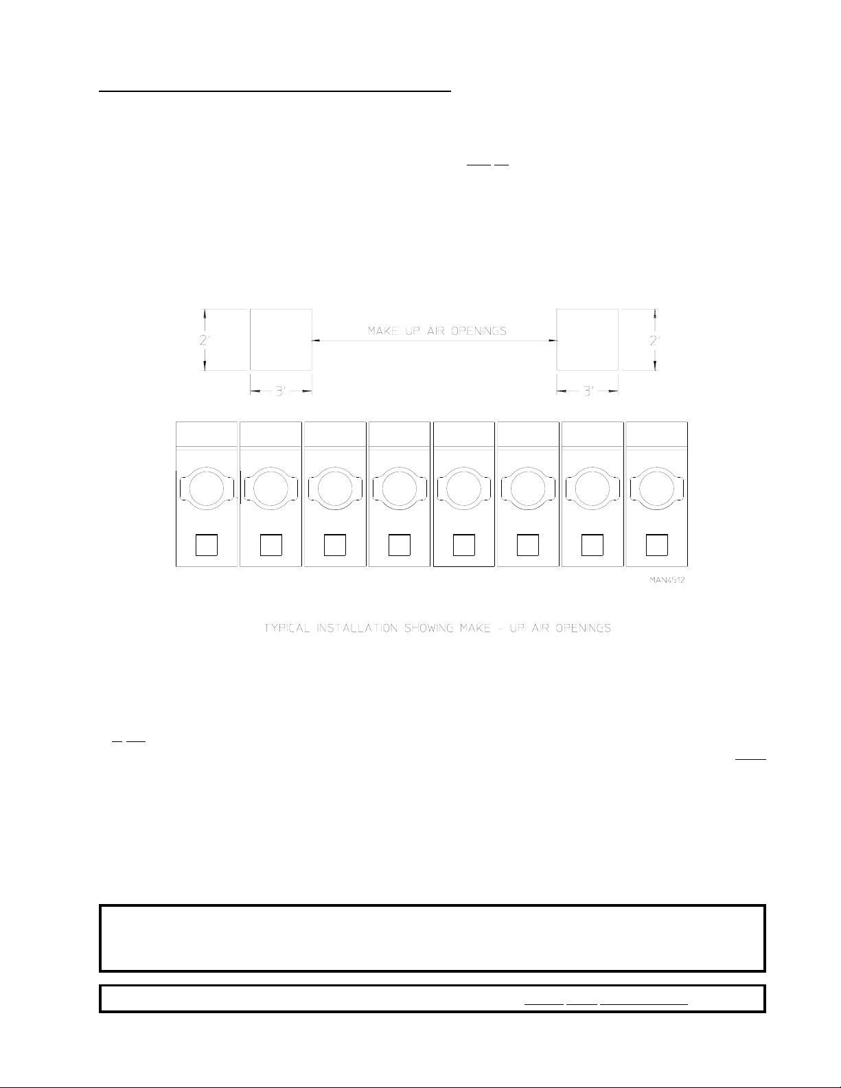
EXAMPLE: For a bank of eight (8) dryers, two (2) unrestricted openings measuring 2 feet by 3 feet (0.61
meters by 0.91 meters) are acceptable.
Allowances must be made for remote or constricting passageways or where dryers are located at excessive
altitudes or predominantly low pressure areas.
IMPORTANT: Make-up air must be provided from a source free of dry cleaning solvent fumes.
Make-up air that is contaminated by dry cleaning solvent fumes will result in
irreparable damage to the motors and other dryer components.
NOTE: Component failure due to dry cleaning solvent fumes will VOID THE WARRANTY.
13
Page 18
E. EXHAUST REQUIREMENTS
1. General Exhaust Ductwork Information
Exhaust ductwork should be designed and installed by a qualified professional. Improperly sized ductwork
will create excessive back pressure which results in slow drying, increased use of energy, overheating of
the dryer, and shutdown of the burner by the airflow (sail) switches, burner hi-limits, or basket (tumbler)
hi-heat thermostats. The dryer must be installed with a proper exhaust duct connection to the outside.
CAUTION: This dryer produces combustible lint and must be exhausted to the outdoors.
CAUTION: IMPROPERLY SIZED OR INSTALLED EXHAUST DUCTWORK CAN
CREA TE A POTENTIAL FIRE HAZARD.
The ductwork should be laid out in such a way that the ductwork travels as directly as possible to the
outdoors with as few turns as possible. Single or independent dryer venting is recommended.
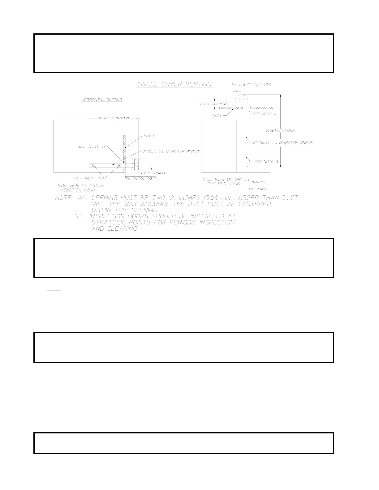
Horizontal Venting:
When single dryer venting is used, the length of the ductwork from the dryer to the outside exhaust outlet,
must not exceed 15 feet (4.6 meters). The minimum diameter of this ductwork must be at least 10-
inches (25.4 cm). In the case of multiple (common) dryer venting, the distance from the last dryer to the
outside exhaust outlet must not exceed 15 feet (4.6 meters). The shape of the ductwork
long as the minimum cross-sectional area is provided. It is suggested that the use of 90° turns
use 30° and/or 45° angles instead. The radius of the elbows should preferably be 1-1/2 times the
diameter of the duct. Including basket (tumbler)/dryer elbow connections or elbows used for outside
protection from the weather, no more than two (2) elbows should be used in the exhaust duct run. If more
than two (2) elbows are used, the cross-sectional area of the ductwork must be increased.
should be smooth inside with no projections from sheet metal screws or other obstructions, which will
collect lint. When adding ducts, the duct to be added should overlap the duct to which it is to be connected.
ALL ductwork joints must be taped to prevent moisture and lint from escaping into the building. Inspection
doors should be installed at strategic points in the exhaust ductwork for periodic inspection and cleaning of
lint from the ductwork.
is not critical so
ALL ductwork
be avoided;
Vertical Venting:
When single dryer venting is used, the length of the ductwork from the dryer to the outside exhaust outlet,
must not exceed 20 feet (6.1 meters). The minimum diameter of this ductwork must be at least
12-inches (30.48 cm) even though the dryer exhaust duct for gas and electric units is only 10-inches (25.4
cm). In the case of multiple (common) dryer venting, the distance from the last dryer to the outside exhaust
outlet should not exceed 20 feet (6.1 meters). The shape of the ductwork
minimum cross-sectional area is provided. It is suggested that the use of 90º turns
or 45º bends instead. The radius of the elbows should preferably be 1-1/2 times the diameter of the duct.
ALL ductwork should be smooth inside with no projections from sheet metal screws or other obstructions,
which will collect lint. When adding ducts, the duct to be added should overlap the duct to which it is to be
connected.
building. Inspection doors should be installed at strategic points in the exhaust ductwork for periodic
inspection and cleaning of lint from the ductwork.
ALL ductwork joints must be taped to prevent moisture and lint from escaping into the
is not so critical so long as the
be avoided; use 30º and/
IMPORTANT: It is recommended that exhaust or booster fans not be used in the exhaust ductwork
system.
IMPORTANT: Exhaust back pressure measured by a manometer in the exhaust duct must be no less
than 0 and must not exceed 0.3 inches (0.74 mb) of water column (W .C.).
14
Page 19
IMPORTANT: Minimum ductwork diameter for horizontal venting is 10-inches (25.4 cm) and for
vertical venting the minimum is 12-inches (30.48 cm).
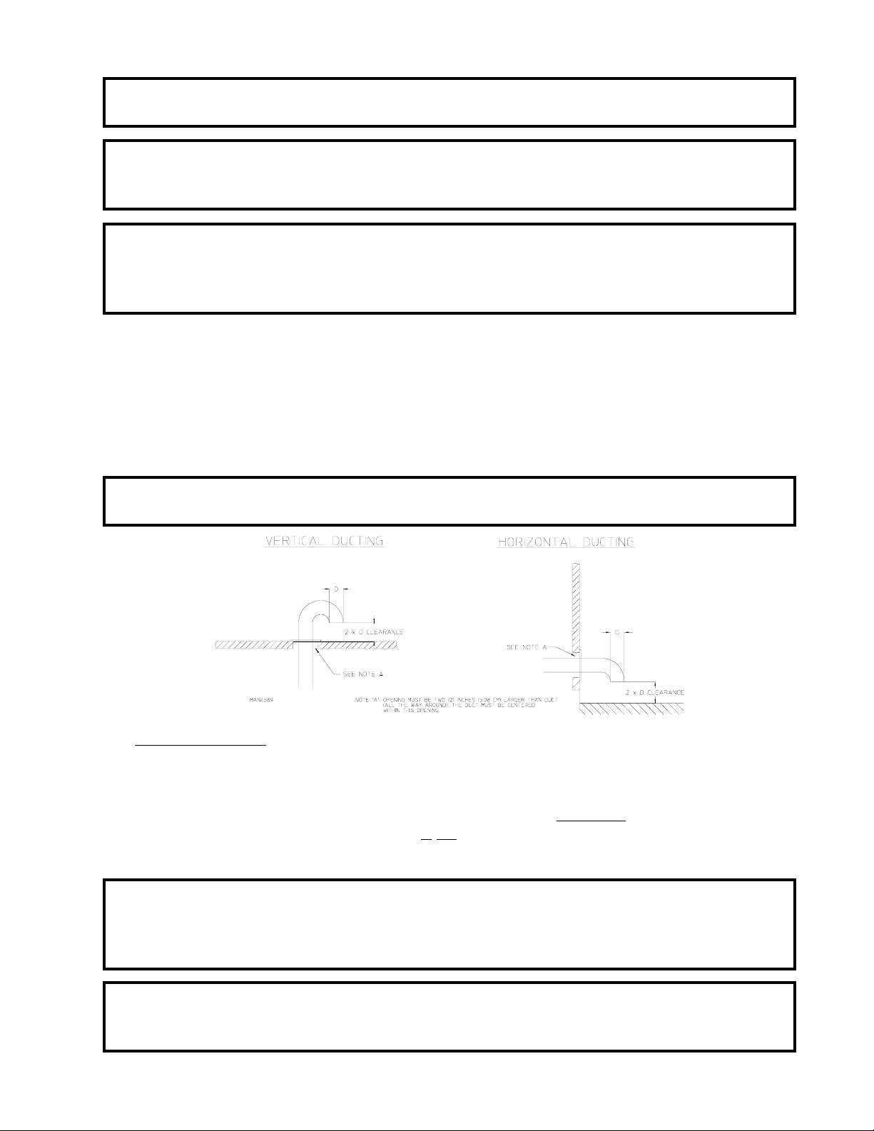
NOTE: When the exhaust ductwork passes through a wall, ceiling, or roof made of combustible
materials, the opening must be 2-inches (5.08 cm) larger than the duct (all the way around).
The duct must be centered within this opening.
NOTE: As per the National Fuel Gas Code, “Exhaust ducts for type 2 clothes dryers shall be
constructed of sheet metal or other noncombustible material. Such ducts shall be equivalent in
strength and corrosion resistance to ducts made of galvanized sheet steel not less than
0.0195-inches (26 gauge [0.05 mm]) thick.”
a. Outside Ductwork Protection
1) To protect the outside end of the horizontal ductwork from the weather , a 90° elbow bent downward
should be installed where the exhaust exits the building. If the ductwork travels vertically up
through the roof, it should be protected from the weather by using a 180° turn to point the opening
downward. In either case, allow at least twice the diameter of the duct between the duct opening
and the nearest obstruction.
IMPORTANT: DO NOT use screens, louvers, or caps on the outside opening of the exhaust
ductwork.
2. Single Dryer Venting
When possible, it is suggested to provide a separate exhaust duct for each dryer. The exhaust duct should
be laid out in such a way that the ductwork travels as directly as possible to the outdoors with as few turns
as possible. It is suggested that the use of 90° turns in the ducting be avoided; use 30° and/or 45° angles
instead. The shape of the exhaust ductwork is not critical so long as the minimum cross section area is
provided.
IMPORTANT: Minimum duct size for a dryer that is vented horizontally is 10-inches (25.4 cm) for a
round duct or an equivalent of 80 square inches (516 square centimeters). THE
DUCT SIZE MUST NOT BE REDUCED ANYWHERE DOWNSTREAM OF
THE DRYER.
IMPORTANT: Exhaust back pressure measured by a manometer at each basket (tumbler) exhaust
duct area must be no less than 0 and must not exceed 0.3 inches (0.74 mb) of water
column (W .C.).
15
Page 20
IMPORTANT: Minimum duct size for a dryer that is vented vertically is 12-inches (30.48 cm) for a
round duct or an equivalent of 120 square inches (774 square centimeters). THE
DUCT SIZE MUST NOT BE REDUCED ANYWHERE DOWNSTREAM OF
THE DRYER.
IMPORTANT: For extended ductwork runs, the cross section area of the ductwork can only be
increased to an extent. When the ductwork approaches the maximum limits noted in
this manual, a professional heating, ventilating, and air-conditioning (HVAC) firm
should be consulted for proper venting information.
ALL ductwork should be smooth inside with no projections from sheet metal screws or other obstructions,
which will collect lint. When adding ducts, the duct to be added should overlap the duct to which it is to be
connected. ALL ductwork joints must be taped to prevent moisture and lint from escaping into the
building. Inspection doors should be installed at strategic points in the exhaust ductwork for periodic
inspection and cleaning of lint from the ductwork.
NOTE: When the exhaust ductwork passes through a wall, ceiling, or roof made of combustible
materials, the opening must be 2-inches (5.08 cm) larger than the duct (all the way around).
The duct must be centered within this opening.
a. Outside Ductwork Protection
1) To protect the outside end of the horizontal ductwork from the weather , a 90° elbow bent downward
should be installed where the exhaust exits the building. If the ductwork travels vertically up
through the roof, it should be protected from the weather by using a 180° turn to point the opening
downward. In either case, allow at least twice the diameter of the duct between the duct opening
and the nearest obstruction.
IMPORTANT: DO NOT use screens, louvers, or caps on the outside opening of the exhaust
ductwork.
16
Page 21
Multiple Dryer (Common) Venting
3.
If it
is not feasible to provide separate exhaust ducts for each dryer, ducts from individual dryers may be
channeled into a “common main duct.” The individual ducts should enter the bottom or side of the main
duct at an angle not more than 45º in the direction of airflow and should be spaced at least 38-5/16” (97.31
cm) apart. The main duct should be tapered, with the diameter increasing before each individual duct
(10-inch [25.4 cm] minimum) is added.
IMPORTANT: No more than four (4) dryers should be connected to main common duct.
The main duct may be any shape so long as the minimum cross section area is provided. The illustrations
on page 18 show the minimum cross section area for multiple dryer round or square venting. These
figures must be increased 10 square inches (64.52 square centimeters) when rectangular main ducting is
used, and the ratio of duct width to depth should not be greater than 3-1/2 to 1. These figures must be
increased in proportion if the main duct run from the last dryer to where it exhausts to the outdoors is
unusually long (over 15 feet [4.6 meters]) or has numerous (more than two [2] elbows in it). In calculating
ductwork size, the cross section area of a square or rectangular duct must be increased twenty percent
(20%) for each additional 15 feet (4.6 meters). The diameter of a round exhaust must be increased ten
percent (10%) for each additional 15 feet (4.6 meters). Each 90º elbow is equivalent to an additional 30
feet (9.14 meters) and each 45º elbow is equivalent to an additional 15 feet (4.6 meters).
IMPORTANT: For extended ductwork runs, the cross section area of the ductwork can only be
increased to an extent. Maximum proportional ductwork runs cannot exceed 15 feet
(4.6 meters) with two (2) elbows. When the ductwork approaches the maximum
limits as noted in this manual, a professional heating, ventilating, and air-conditioning
(HV AC) firm should be consulted for proper venting information.
The ductwork should be smooth inside with no projections from sheet metal screws or other obstructions,
which will collect lint. When adding ducts, the duct to be added should overlap the duct to which it is to be
connected. ALL ductwork joints must be taped to prevent moisture and lint from escaping into the
building. Inspection doors should be installed at strategic points in the exhaust ductwork for periodic
inspection and cleaning of lint from the ductwork.
NOTE: When the exhaust ductwork passes through a wall, ceiling, or roof made of combustible
materials, the opening must be 2-inches (2.54 cm) larger than the duct (all the way around).
The duct must be centered within this opening.
a. Outside Ductwork Protection
1) To protect the outside end of the horizontal ductwork from weather, a 90º elbow bent downward
should be installed where the exhaust exits the building. If the ductwork travels vertically up
through the roof, it should be protected from the weather by using a 180º turn to point the opening
downward. In either case, allow at least twice the diameter of the duct between the duct opening
and the nearest obstruction.
IMPORTANT: DO NOT use screens, louvers, or caps on the outside opening of the exhaust
ductwork.
17
Page 22
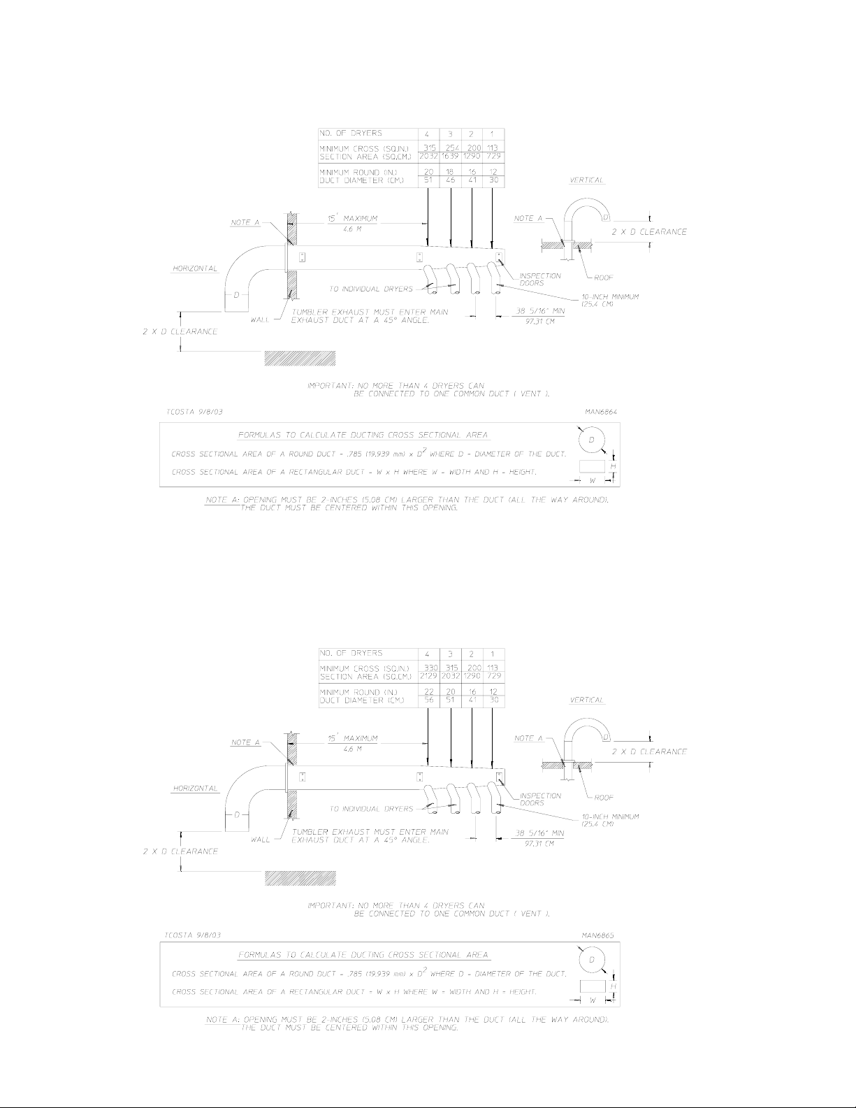
Multiple Dryer Venting (Gas) with 10-Inch (25.4 cm) Diameter
900 cfm (25.48 cmm) Exhaust Connections at Common Duct
Multiple Dryer Venting (S team and Electric) with 10-Inch (25.4 cm) Diameter
1200 cfm (33.98 cmm) Exhaust Connections at Common Duct
18
Page 23
F. ELECTRICAL INFORMATION
1. Electrical Requirements
ALL electrical connections must be made by a properly licensed and competent electrician. This
is to ensure that the electrical installation is adequate and conforms to local and state regulations or codes.
In the absence of such codes, ALL electrical connections, materials, and workmanship must conform to
the applicable requirements of the National Electrical Code ANSI/NFPA NO. 70-LATEST EDITION or in
Canada, the Canadian Electrical Codes Parts 1 & 2 CSA C22.1-1990 or LATEST EDITION.
IMPORTANT: Failure to comply with these codes or ordinances, and/or the requirements stipulated
in this manual can result in personal injury or component failure.
NOTE: Component failure due to improper installation will VOID THE WARRANTY.
Each dryer should be connected to an independently protected branch circuit. The dryer must be connected
with copper wire only. DO NOT use aluminum wire, which could cause a fire hazard. The copper
conductor wire/cable must be of proper ampacity and insulation in accordance with electric codes for
making ALL service connections.
NOTE: The use of aluminum wire will VOID THE WARRANTY.
IMPORTANT: A separate protected circuit must be provided to each dryer.
NOTE: An individual ground circuit must be provided to each dryer, do not daisy chain.
IMPORTANT: The dryer must be connected to the electric supply shown on the data label. In the
case of 208 VAC or 230/240 V AC, the supply voltage must match the electric service
specifications of the data label exactly.
IMPORTANT: The wire size must be properly sized to handle the related current.
WARNING: 208 VAC AND 230/240 V AC ARE NOT THE SAME. Any damage done to dryer
components due to improper voltage connections will automatically VOID THE
WARRANTY.
NOTE: Component failure due to improper voltage application will VOID THE WARRANTY.
NOTE: ADC reserves the right to make changes in specifications at any time without notice or
obligation.
19
Page 24
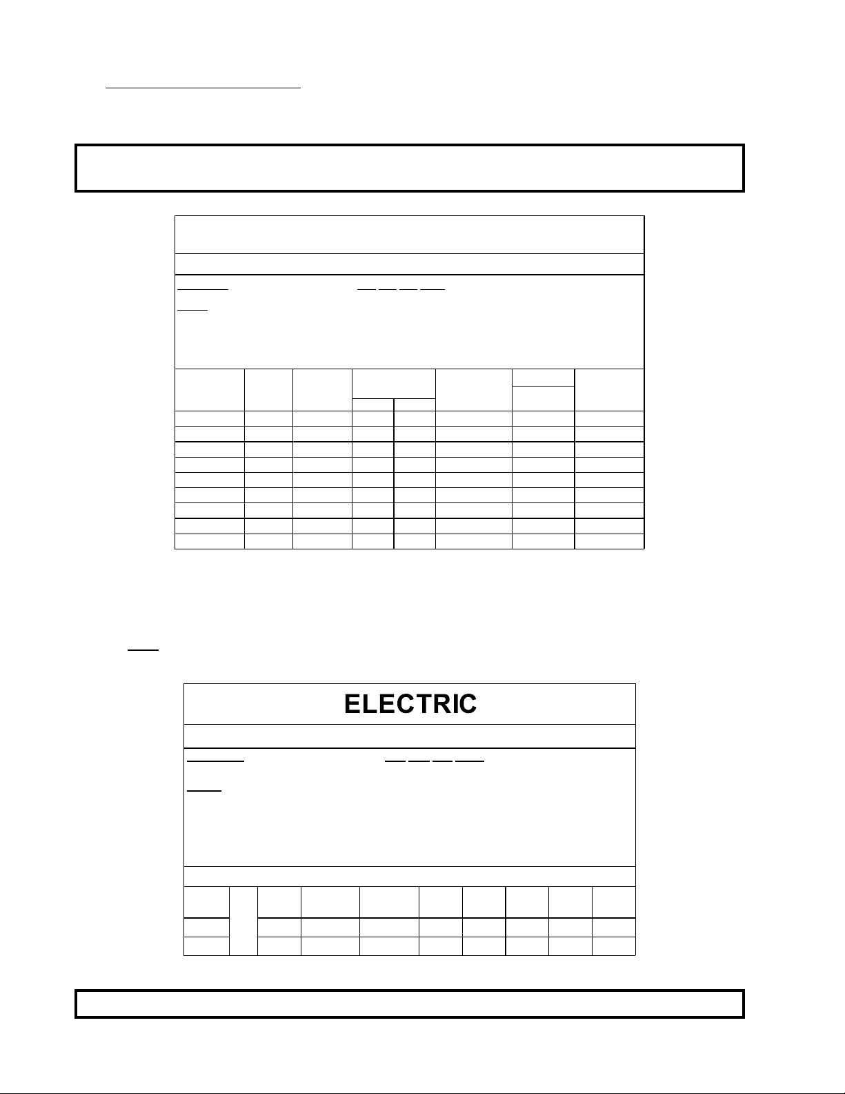
2. Electrical Service Specifications
a. Gas and Steam Models Only
IMPORTANT: Figures shown are for non-reversing models only . For reversing models contact the
factory .
GAS AND STEAM
ELECTRICAL SERVICE SPECIFICATIONS (PER DRYER)
IMPORTANT:
NOTES
B.
C.
SERVICE
VOLTAGE
120 1 2 13.0 — * 20 20
208 1 2 7.6 — * 15 15
230/240 1 2 7.0 7.8 * 15 15
208 3 3 4.7 — * 15 15
230/240 3 3 4.9 5.6 * 15 15
380 3 4** — 2.9 * 15 15
400 3 4** — 3.2 * 15 15
416 3 4** — 3.1 * 15 15
460/480 3 3 2.8 — * 15 15
* AWG Stranded Wire Type...size wire as per National Electrical Code or local codes. 9/22/03
** 3-Wire available.
208 VAC AND 230/240 VAC ARE
: A.
When fuses are used they must be dual element, time delay, current limiting, class RK1 or RK5 ONLY.
Calculate/determine correct fuse value, by applying either local and/or National Electrical Codes to listed
appliance amp draw data.
Circui t breakers are thermal-magnetic (industrial) motor curve type ONLY. Fo r o the rs , c alculate/veri fy
correct breaker size according to appliance amp draw rating and type of breaker used.
Circui t breakers for 3-phase (3Ø) dryers must be 3-pole type.
PHASE
WIRE
SERVICE
NOT THE SAME. When ordering, specify exact voltage.
APPROX.
AMP DRAW
60 Hz 50 Hz
MINIMUM
WIRE SIZE
FUSING
Dual Element
Ti me De l ay
CIRCUIT
BREAKER
b. Electric Models Only
ALL electrically heated dryers must be connected to the electric service shown on the data label. The
connecting wires must be properly sized to handle the rated current.
ELECTRICAL SERVICE SPECIFICATIONS (PER DRYER)
IMPORTANT: 208 VAC and 230/240 VAC ARE NOT THE SAME. When ordering, specify exact
NOTES
kW
30 90 80 79 54 52 49 40 39
36 107 94 94 63 60 58 48 46
voltage.
:A.
When fuses are used they must be dual element, time delay, current limiting, class
RK1 or RK5 ONLY. Calculate/determine correct fuse value, by applying either local
and/or National Electrical Codes to listed appliance amp draw data.
B.
Circuit breakers are thermal-magnetic (industrial) type ONLY. Fo r o thers ,
calculate/ verify correct breaker size according to appliance amp draw rating and type
of breaker used.
C.
Circuit breakers for 3-phase (3ø) dryers must be 3-pole type.
APPLIED VOLTAGE / 3 PHASE
208
(60 Hz)
AMP DRAW
APPROXIMATE
230/240
(50 Hz)
230/240
(60 Hz)
380
(50 Hz)
400
(50 Hz)
416
(50 Hz)
460
(60 Hz)
480
(60 Hz)
9/22/03
IMPORTANT: 3-phase (3ø) figures shown are for a 3-wire service only .
20
Page 25
3. Grounding
A ground (earth) connection must be provided and installed in accordance with state and local codes. In
the absence of these codes, grounding must conform to applicable requirements of the National Electrical
Code ANSI/NFPA NO. 70-LATEST EDITION, or in Canada, the installation must conform to applicable
Canada Standards: Canadian Electrical Codes Parts 1 & 2 CSA C22.1-1990 or LATEST EDITION. The
ground connection may be to a proven earth ground at the location service panel.
For added personal safety , when possible, it is suggested that a separate ground wire (no. 18 minimum) be
connected from the ground connection of the dryer to a grounded cold water pipe. DO NOT ground to a
gas pipe or hot water pipe. The grounded cold water pipe must have metal-to-metal connection ALL the
way to the electrical ground. If there are any nonmetallic interruptions, such as, a meter, pump, plastic,
rubber, or other insulating connectors, they must be jumped out with no. 4 copper wire and securely
clamped to bare metal at both ends.
IMPORTANT: For personal safety and proper operation, the dryer must be grounded.
Provisions are made for ground connection in each dryer at the electrical service connection area.
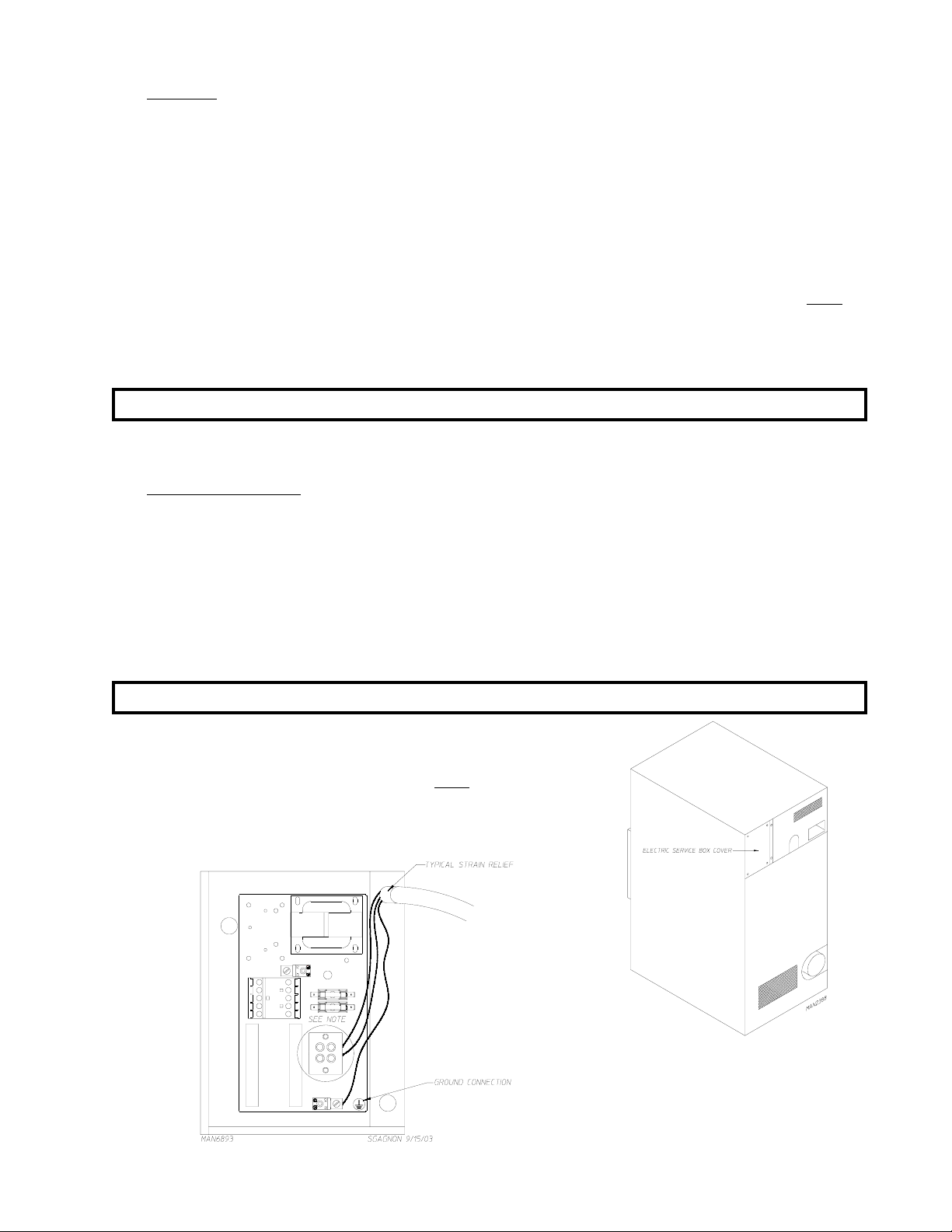
4. Electrical Connections
A wiring diagram is located inside the control box for connection data.
If local codes permit, power to the dryer can be made by the use of a flexible U.L. listed power cord/pigtail
(wire size must conform to rating of dryer), or the dryer can be hard wired directly to the service breaker
panel. In both cases, a strain relief must be installed where the wiring enters the dryer.
a. Gas and Steam Models Only
IMPORTANT: A separate protected circuit must be provided to each dryer.
1) Single-Phase (1ø) Wiring Connections/Hookup
The electrical input connections on ALL single-phase (1ø)
gas dryers and steam dryers are made into the rear service
box located at the upper left area of the dryer.
21
Page 26
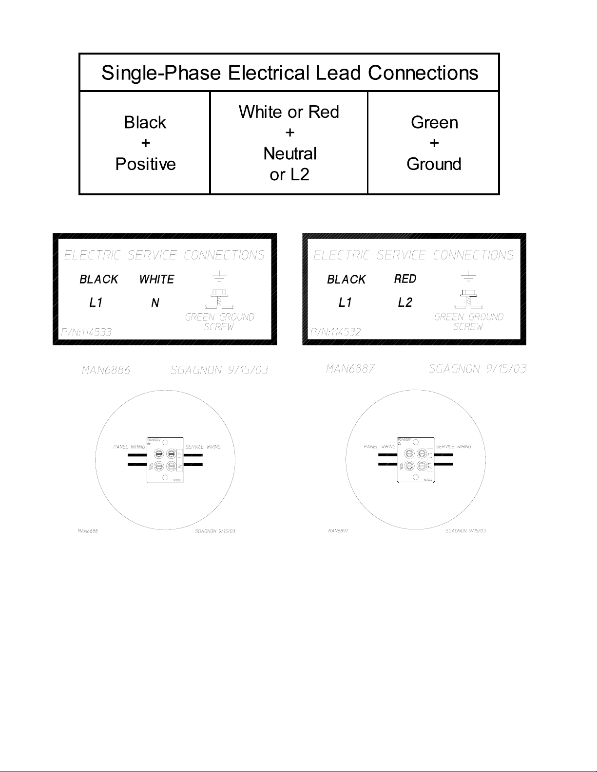
FOR 1 10V APPLICATIONS
FOR 208-230/240V APPLICA TIONS
A ground lug is provided in the rear electrical box to connect your service ground.
22
Page 27
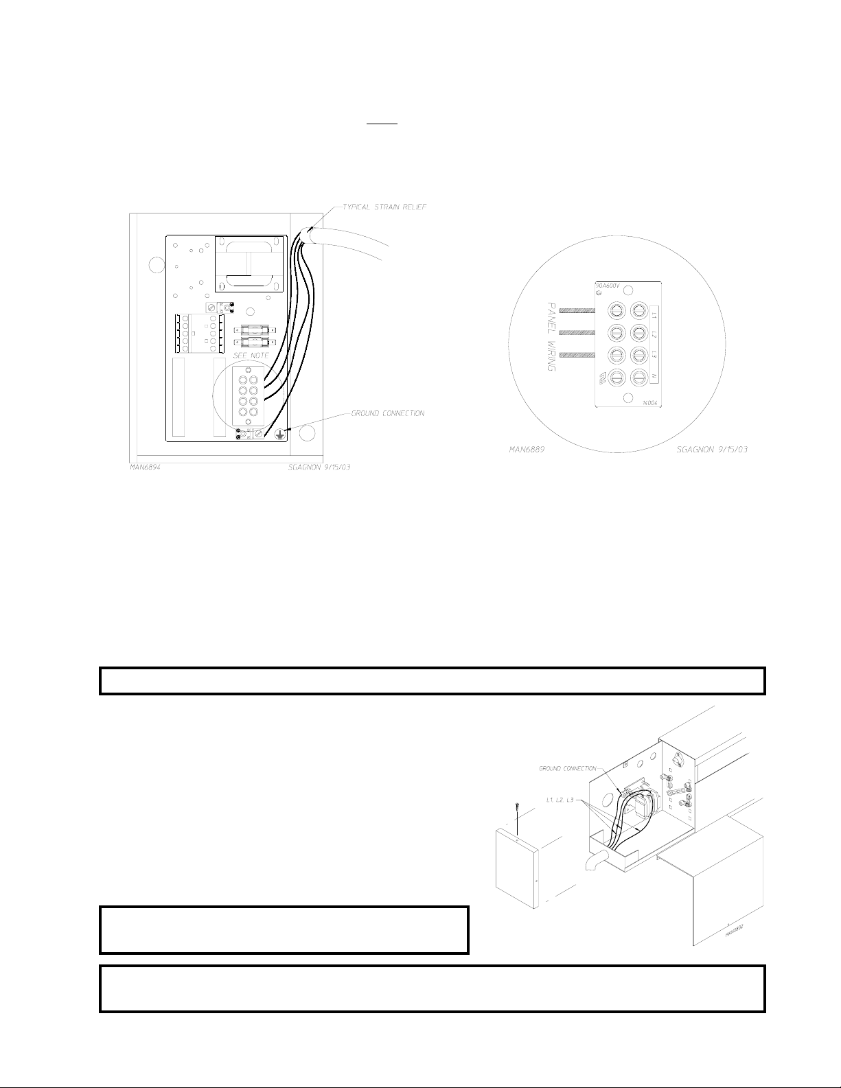
2) 3-Phase (3ø) Wiring Connections/Hookup
The electrical connections on
service box located at the upper left area of the dryer. The electrical connections are made at the
power distribution block located in the service box. The ground connection is made to the copper
lug, also provided in this box. To gain access, the service box cover must be removed.
The neutral will only be used on 4-wire service. This is typical for 380-416V, 50 Hz.
ALL 3-phase (3ø) gas and steam dryers are made into the rear
b. Electrically Heated Models Only
The only electrical input connections to the dryer are the 3-phase (3ø) power leads (L1, L2, L3, and
sometimes neutral) and ground. Single-phase (1ø) power for the control circuit and for any singlephase (1ø) motors (if present) is done internally to the dryer by the factory at the oven contactor. No
single-phase (1ø) input connection is required on a 3-phase (3ø) dryer.
CAUTION: The dryer must be grounded. A ground lug has been provided for this purpose.
Input connection wiring must be sized properly to
handle the dryer’s current draw. This information is
printed on the dryer’s data label.
The electrical input connections are made at the
electric oven contactor located inside the assembly at
the rear center upper section of the dryer. The ground
connection is made to a copper lug also provided in
this area. To gain access, remove oven rear service
cover.
IMPORTANT: A strain relief must be used where the
input wiring enters the oven assembly .
NOTE: Electrically heated service (amperage) specifications/requirements can be found under
electrical service specifications.
23
Page 28
G. GAS INFORMATION
It is your responsibility to have ALL plumbing connections made by a qualified professional to assure that the gas
plumbing installation is adequate and conforms to local and state regulations or codes. In the absence of such
codes,
ALL plumbing connections, materials, and workmanship must conform to the applicable requirements of
the National Fuel Gas Code ANSI Z223.1-LATEST EDITION, or in Canada, the Canadian Installation Codes
CAN/CGA-B149.1-M91 (Natural Gas) or CAN/CGA-B149.2-M91 (Liquid Propane [L.P.] Gas) or LATEST
EDITION.
IMPORTANT: Failure to comply with these codes or ordinances, and/or the requirements stipulated
in this manual, can result in personal injury and improper operation of the dryer.
The dryer and its individual shutoff valves must be disconnected from the gas supply piping system during any
pressure testing of that system at test pressures in excess of 1/2 psig (3.5 kPa). The dryer must be isolated
from the gas supply piping system by closing its individual manual shutoff valve during any pressure test of the
gas supply system at test pressures equal to or less than 1/2 psig (3.5 kPa).
IMPORTANT: Failure to isolate or disconnect the dryer from supply as noted can cause irreparable
damage to the gas valve VOIDING THE WARRANTY.
W ARNING: FIRE OR EXPLOSION COULD RESULT.
1. Gas Supply
The gas dryer installation must meet the American National Standard...National Fuel Gas Code ANSI
Z223.1-LA TEST EDITION, or in Canada, the Canadian Installation Codes CAN/CGA-B149.1 M91 (Natural
Gas) or CAN/CGA-B149.2-M91 (L.P. Gas) or LATEST EDITION, as well as local codes and ordinances
and must be done by a qualified professional.
NOTE: Undersized gas piping will result in ignition problems, slow drying, increased use of energy , and
can create a safety hazard.
The dryer must be connected to the type of heat/gas indicated on the data label. If this information does
not agree with the type of gas available, DO NOT operate the dryer. Contact the reseller who sold the
dryer or contact the ADC factory.
IMPORTANT: Any burner changes or conversions must be made by a qualified professional.
The input ratings shown on the data label are for elevations up to 2,000 feet (610 meters), unless elevation
requirements of over 2,000 feet (610 meters) were specified at the time the dryer order was placed with
the factory . The adjustment or conversion of dryers in the field for elevations over 2,000 feet (610 meters)
is made by changing each burner orifice. If this conversion is necessary , contact the reseller who sold the
dryer or contact the ADC factory.
IMPORTANT: THIS GAS DRYER IS NOT PROVIDED WITH AN INTERNAL GAS SUPPLY
SHUTOFF AND AN EXTERNAL GAS SUPPL Y SHUTOFF MUST BE
PROVIDED.
24
Page 29
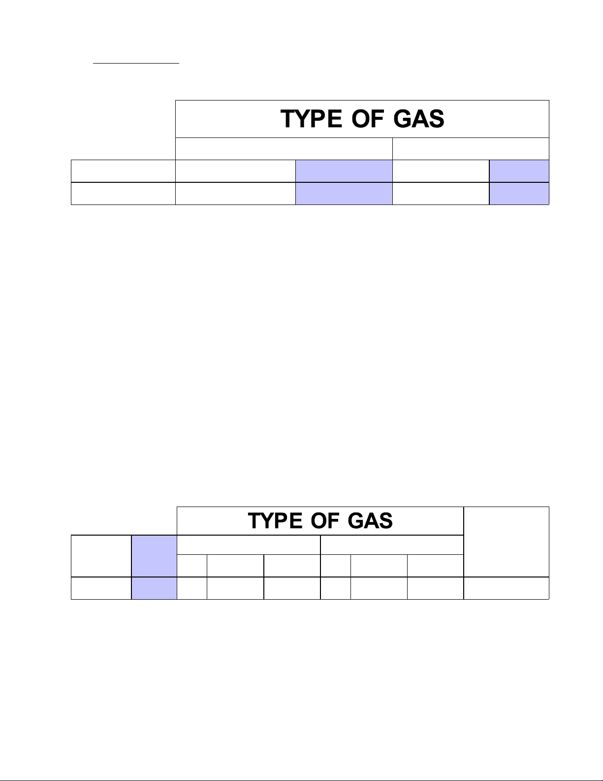
Technical Gas Data
2.
a. Gas Specifications
NA TURA L LIQUID PROPA NE
Mani fold P r e s sure* 3.5 inches W.C.
In-Line Pressure 6.0 - 12.0 inches W.C.
Shaded areas are stated in metric equivalents
* Measured at outlet side of gas valve pressure tap when gas valve is on.
b. Gas Connections:
Inlet connection -------------3/4” N.P.T .
Inlet supply size -------------3/4” N.P .T . (minimum)
Btu/hr input (per dryer) ----200,000 (50,400 kcal/hr)
1) Natural Gas
Regulation is controlled by the dryer’s gas valve’s internal regulator. Incoming supply pressure
must be consistent between a minimum of 6.0 inches (14.92 mb) and a maximum of 12.0 inches
(29.9 mb) water column pressure (W.C.).
2) Liquid Propane (L.P.) Gas
Dryers made for use with L.P. gas have the gas valve’s internal pressure regulator blocked open so
that the gas pressure must be regulated upstream of the dryer. The pressure measured at each
gas valve pressure tap must be a consistent 10.5 inches (26.1 mb) water column. There is no
regulator or regulation provided in an L.P. dryer. The water column pressure must be regulated at
the source (L.P. tank) or an external regulator must be added to each dryer.
8.7 mb
14.92 - 29.9 mb
10.5 inches W.C.
11. 0 inc hes W. C.
26.1 mb
27.4 mb
Btu/hour
Rating
200,000
Shaded area is stated in metric equivalent
* Drill Measurement Size (D.M.S.) equivalents are as follows:
Natural Gas .......................... #29 = 0.1360” (3.4544 mm).
Liquid Propane Gas .............. #47 = 0.0785” (1.9939 mm).
kcal/hr
Rating
50,400
Qty. D .M.S.* Part No. Qty. D .M.S.* Part No .
4 #29 140820 4 #47 140805 882575
Natural Liquid Propane
Liquid
Propane
Conversion Kit
Part Number
25
Page 30
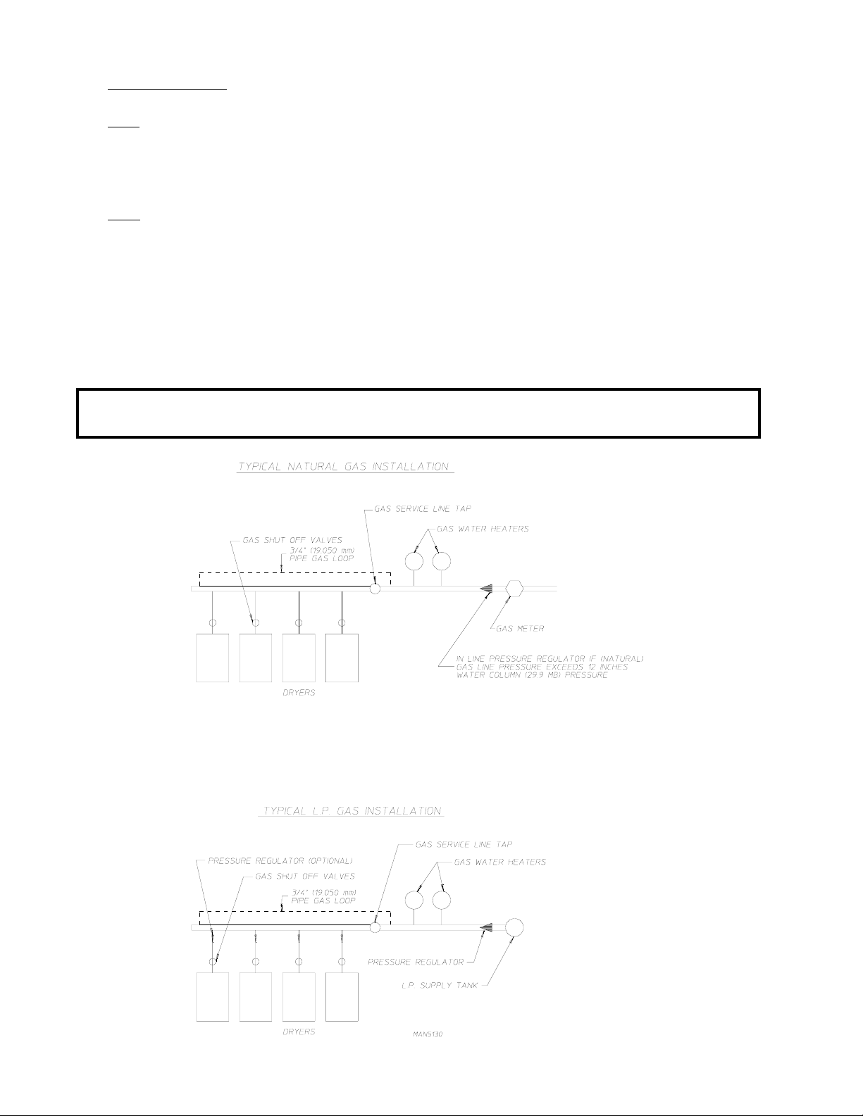
3. Piping/Connections
ALL components/materials must conform to National Fuel Gas Code Specifications ANSI Z223.1-LATEST
EDITION, or in Canada, CAN/CGA-B149.1-M91 (Natural Gas) or CAN/CGA-B149.2-M91 (Liquid
Propane [L.P.] Gas) or LATEST EDITION (for General Installation and Gas Plumbing), as well as local
codes and ordinances and must be done by a qualified professional. It is important that gas pressure
regulators meet applicable pressure requirements, and that gas meters be rated for the total amount of
ALL the appliance Btus being supplied.
The dryer is provided with a 3/4” N.P.T. inlet pipe connection located at the right side of the base of the
dryer. The minimum pipe size (supply line) to the dryer is 3/4” N.P.T. For ease in servicing, the gas supply
line of each dryer must have its own shutoff valve.
The size of the main gas supply line (header) will vary depending on the distance this line travels from the
gas meter or, in the case of L.P. gas, the supply tank, other gas-operated appliances on the same line, etc.
Specific information regarding supply line size should be determined by the gas supplier.
NOTE: Undersized gas supply piping can create a low or inconsistent pressure, which will result in
erratic operation of the burner ignition system.
26
Page 31
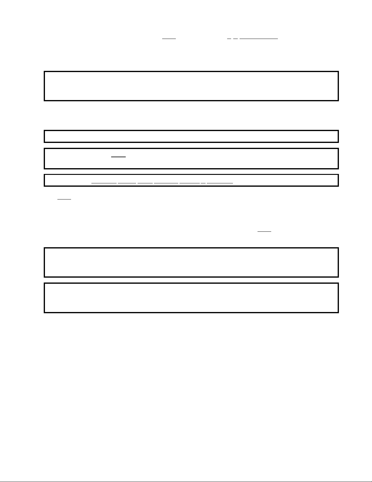
Consistent gas pressure is essential at
mm) pipe gas loop be installed in the supply line servicing a bank of dryers. An in-line pressure regulator
must be installed in the gas supply line (header) if the (natural) gas pressure exceeds 12.0 inches (29.9
mb) of water column (W.C.) pressure.
ALL gas connections. It is recommended that a 3/4-inch (19.05
NOTE: A water column test pressure of 3.5 inches (8.7 mb) for natural gas and 10.5 inches (26.1 mb)
for liquid propane (L.P .) dryers is required at the gas valve pressure tap of each dryer for
proper and safe operation.
A 1/8” N.P.T. plugged tap, accessible for a test gauge connection, must be installed in the main gas supply
line immediately upstream of each dryer.
IMPORTANT: Pipe joint compounds that resist the action of natural gas and L.P . gas must be used.
IMPORTANT: T est ALL connections for leaks by brushing on a soapy water solution (liquid
detergent works well).
WARNING: NEVER TEST FOR LEAKS WITH A FLAME!!!
ALL components/materials must conform to National Fuel Gas Code Specifications ANSI Z223.1-LATEST
EDITION, or in Canada, CAN/CGA-B149.1-M91 (Natural Gas) or CAN/CGA-B149.2-M91 (L.P. Gas)
or LATEST EDITION (for General Installation and Gas Plumbing), as well as local codes and ordinances
and must be done by a qualified professional. It is important that gas pressure regulators meet applicable
pressure requirements, and that gas meters be rated for the total amount of ALL the appliance Btus being
supplied.
IMPORTANT: The dryer and its individual shutoff valve must be disconnected from the gas supply
piping system during any pressure testing of that system at test pressures in excess of
1/2 psig (3.5 kPa).
NOTE: The dryer must be isolated from the gas supply piping system by closing its individual manual
shutoff valve during any pressure test of the gas supply system at test pressures equal to or less
than 1/2 psig (3.5 kPa).
27
Page 32
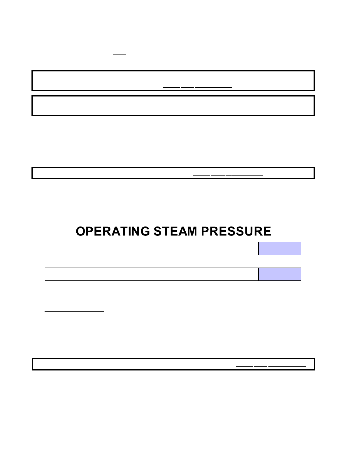
H. STEAM INFORMATION
It is your responsibility to have ALL plumbing connections made by a qualified professional to assure that the
steam plumbing installation is adequate and conforms with local and state regulations or codes.
IMPORTANT: Failure to comply with the requirements stipulated in this manual can result in
component failure, which will
NOTE: The dryer is manufactured with a pneumatic (piston) damper system, which requires an
external air supply of 0.75 cfh @ 80 psi +/- 10 psi (0.02 cmh @ 5.51 bar +/- 0.69 bar).
1. Steam Coil PH Level
The normal PH level for copper type steam coils must be maintained between a value of 8.5 to 9.5. For
steel type steam coils the PH level must be maintained between a value of 9.5 to 10.5. These limits are set
to limit the acid attack of the steam coils.
IMPORTANT: Coil failure due to improper PH level will VOID THE WARRANTY.
2. Steam Requirements - High Pressure
Inlet -------- 1” supply line connection -- qty . one (1) at top manifold.
Return ----- 1” return line connection -- qty . one (1) at top manifold.
VOID THE WARRANTY.
MAXIMUM 125 psig
862 kPa
HEAT INPUT (NORMAL LOAD) 7 Bhp
CONSUMPTION (APPROXIMATE) @ 125 psi (8.62 bar) 238.7 lbs/hr
Shaded areas are stated in metric equivalents
* The minimum operating pressure is 100 psig (689.47 kPa) for optimum results.
3. Installation Instructions
To insure an adequate supply of steam is provided, be sure that the steam supply lines and steam return
lines are sized and laid out as stipulated in this manual. Inadequate steam supply lines and steam return
lines or improper steam plumbing will result in poor performance and can cause component failure. Clean,
dry steam must be provided to the dryer.
108.3 kg/hr
IMPORTANT: Steam coil failure due to water hammer by wet steam will VOID THE WARRANTY.
28
Page 33
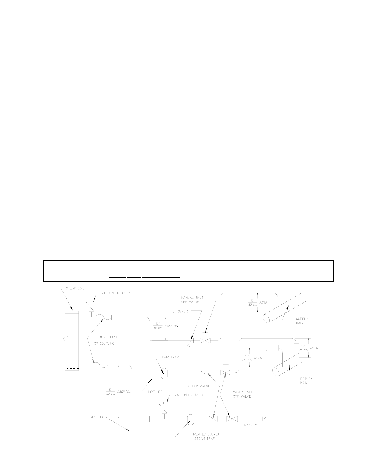
a. The pressure of the condensate in the steam supply line will cause water hammer and subsequent heat
exchanger (steam coil) failure. The steam supply connection into the main supply line must be made
with a minimum 10-inch (25.4 cm) riser. This will prevent any condensate from draining towards the
dryer.
b. The steam supply line to the dryer must include a 12-inch (30.48 cm) riser along with a drip trap and
check valve. This will prevent any condensate from entering the steam coil.
c. Flexible hoses or couplings must be used. The dryer vibrates slightly when it runs and this will cause
the steam coil connections to crack if they are hard piped to the supply and return mains.
d. Shutoff valves for each dryer should be installed in the supply line, return line, and drip trap return line.
This will allow the dryer to be isolated from the supply main and the return main if the dryer needs
maintenance work.
e. Install an inverted bucket steam trap and check valve at least 12-inches (30.48 cm) below the steam
coil as close to the coil as possible.
1) A trap with a capacity of 700 lbs (317.51 kg) of condensate per hour at 125 psi (8.62 bar) is needed
for each unit.
f. The supply line and the return line should be insulated. This will save energy and provide for the safety
of the operator and maintenance personnel.
g. Water pockets in the supply line, caused by low points, will provide wet steam to the coil possibly
causing steam coil damage.
(6.35 mm) for every 1 foot (0.31 meters) back towards the steam supply header causing the condensate
in the line to drain to the header. Install a bypass trap in any low point to eliminate wet steam.
ALL horizontal runs of steam supply piping should be pitched 1/4-inch
IMPORTANT: Flexible hose/coupling must be used. Coil failure due to hard plumbing connections
will VOID THE WARRANTY .
29
Page 34
Steam Damper Air System Connections
4.
The dryer is manufactured with a pneumatic (piston) damper system, which requires an external supply of
compressed air. The air connection is made to the steam damper solenoid valve, which is located at the
rear inner top area of the dryer just in front of the electric service relay box.
a. Air Requirements
COMPRESSED AIR SUPPLY AIR PRESSUR E
Normal 80 psi
Minimum Supply 70 psi
Maxi mum Supply 90 psi
Shaded areas are stated in metric equivalents
b. Air Connection
Air connection to system --- 1/8” N.P.T.
c. No air regulator or filtration is provided with the dryer . External regulation/filtration of 80 psi (5.51 bar)
must be provided. It is suggested that a filter/regulator/gauge arrangement be added to the compressed
air line just before the dryer connection. This is necessary to insure that correct and clean air pressure
is achieved.
5. Steam Damper System Operation
The steam damper shown in Diagram 1 in the illustration on the next page, allows the coil to stay constantly
charged eliminating repeated expansion and contraction. When the damper is opened, the air immediately
passes through the already hot coil, providing instant heat to start the drying process. When the damper is
closed, ambient air is drawn directly into the basket (tumbler), allowing a rapid cool down (Diagram 2).
5.51 bar
4.82 bar
6.20 bar
Diagram 1 shows the damper in the heating (open) mode, allowing heat into the basket (tumbler).
Diagram 2 shows the damper in the cool down (closed) mode, pulling ambient air directly into the basket
(tumbler) without passing through the coils.
30
Page 35
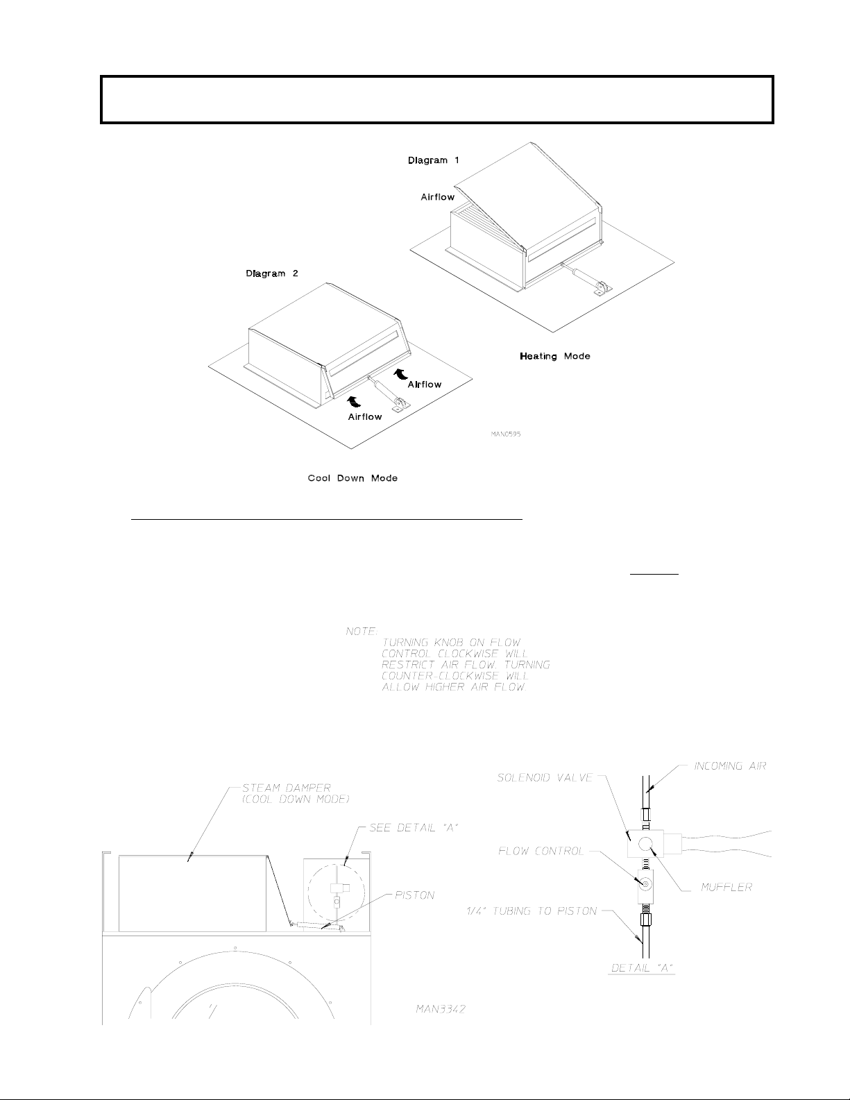
NOTE: With the dryer off or with no air supply , the steam damper is in cool down mode as shown in
Diagram 2.
6. Steam Damper Air Piston (Flow Control) Operation Adjustment
Although the steam damper operation was tested and adjusted prior to shipping at 80 psi (5.51 bar), steam
damper operation must be checked before the dryer is put into operation. Refer to page 30 for instructions
to check steam damper system operation. If steam damper adjustment is necessary, locate the flow
control valve and make the necessary adjustments as noted below.
31
Page 36

I. PREPARATION FOR OPERATION/START-UP
The following items should be checked before attempting to operate the dryer:
1. Read
2. Check incoming supply voltage to be sure that it is the same as indicated on the data label. In the case of
3. GAS MODELS - Check to assure that the dryer is connected to the type of heat/gas indicated on the data
4. GAS AND ELECTRIC MODELS - The sail switch damper assembly was installed and adjusted at the
5. GAS MODELS - Be sure that ALL gas shutoff valves are in the open position.
6. Be sure ALL side and base panels are on the dryer.
7. Check ALL service doors to insure that they are closed and secure.
8. Be sure the lint drawer is securely in place.
9. Rotate the basket (tumbler/drum) by hand to be sure it moves freely.
ALL “CAUTION,” “WARNING,” and “DIRECTION ” labels attached to the dryer.
208 VAC or 230/240 VAC, the supply voltage must match the electric service
label.
factory prior to shipping. However, each sail switch adjustment must be checked to assure that this
important safety control is functioning. (refer to Sail Switch Adjustment on
exactly.
page 34).
10. Check bolts, nuts, screws, terminals, and fittings for security.
11. STEAM MODELS - Check to insure air supply (80 psi [5.51 bar]) is connected to the dryers.
12. STEAM MODELS - Check to insure ALL steam shutoff valves are open.
13. STEAM MODELS - Check steam damper operation.
14. Check basket (tumbler) bearing setscrews to insure they are ALL tight.
32
Page 37
J. PREOPERATIONAL TESTS
ALL dryers are thoroughly tested and inspected before leaving the factory. However, a preoperational test
should be performed before the dryer is publicly used. It is possible that adjustments have changed in transit or
due to marginal location (installation) conditions.
1. Turn on electric power to the dryer.
a. Open
2. Refer to the Operating Instructions for starting your particular model dryer.
3. Gas Dryers
a. When a gas dryer is first started (during initial start-up), it has a tendency not to ignite on the first ignition
ALL shutoff valves (gas models Only).
attempt. This is because the gas supply piping is filled with air, so it may take a few minutes for the air
to be purged from the lines.
NOTE: During the purging period, check to be sure that ALL gas shutoff valves are open.
NOTE: Gas dryers are equipped with a Direct Spark Ignition (DSI) system, which has internal
diagnostics. If ignition is not established within three (3) attempts, the heat circuit in the DSI
module will “LOCKOUT” until it is manually reset. T o reset the DSI system, open and close
the main door and restart the dryer.
b. A gas pressure test should be taken at the gas valve pressure tap of each dryer to assure that the
water column (W.C.) pressure is correct and consistent.
NOTE: Water column pressure requirements (measured at the pressure tap of the gas valve body):
Natural Gas............................. 3.5 inches (8.7 mb) water column.
Liquid Propane (L.P .) Gas ....... 10.5 inches (26.1 mb) water column.
IMPORTANT: There is no regulator provided in an L.P . dryer . The water column pressure must be
regulated at the source (L.P . tank), or an external regulator must be added to each
dryer .
4. Steam Dryers
a. Check to insure that steam damper is functioning properly.
1) The steam damper should not “slam” (open or closed) when it reaches the end of (piston) travel.
Additionally , the steam damper should not bind and/or stop during travel. If either of these conditions
occur, the flow control must be adjusted. Refer to the bottom illustration on page 31 for steam
damper air piston (flow control) operation adjustment instructions.
33
Page 38
5. Electrically Heated Dryers
a. Check to insure that electric oven/contactor assembly is activating.
6. Make a complete operational check of
a. Door Switch(es)
b. Hi-Limit Thermostats
c. Sail Switch (for Gas and Electric Models Only)
ALL safety related circuits:
NOTE: T o check for proper sail switch operation (for gas and electric models only), open the main
door and while holding main door switch plunger in, start dryer. Dryer should start but heat
circuit should not be activated (on). If the heat system is activated, the sail switch is
improperly adjusted and must be adjusted by bending the actuator arm of the sail switch
toward the burner box. If the actuator arm is bent too far toward the burner box of the dryer,
the dryer may not have heat when needed. After any adjustment to the sail switch, the above
procedure must be repeated to verify proper operation of the sail switch.
7. The dryer should be operated through one (1) complete cycle to assure that no further adjustments are
necessary and that ALL components are functioning properly .
BASKET (TUMBLER) COA TING
The basket (tumbler) is treated with a protective coating. W e suggest dampening old garments or cloth material
with a solution of water and nonflammable mild detergent and tumbling them in the basket (tumbler) to remove
this coating.
8. Make a complete operational check of ALL operating controls.
a. For microprocessor model check controller (computer) programs/selections...
1) Each microprocessor controller (computer) has been preprogrammed by the factory with the most
commonly used parameter (program) selections. If computer program changes are required, refer
to the computer programming manual which was shipped with the dryer.
9. Check the electric service phase sequence (3-phase [3ø] models only). While the dryer is operating, check
to see if the blower wheel (impellor/fan) is rotating in the proper direction. Looking from the front, the
blower wheel (impellor/fan) should spin in the clockwise (CW) direction. If it is, the phasing is correct. If
the phasing is incorrect, reverse two (2) of the three (3) leads at connections L1, L2, L3 of the power
supply to the dryer.
IMPORTANT: If the blower wheel (impellor/fan) is rotating in the wrong direction, this will not only
drastically reduce drying efficiency , but it can also cause premature component failure.
34
Page 39
10. Reversing basket (tumbler) dryers should never be operated with less than a 50 lb (22.67 kg) load (dry
weight), since the load’s weight affects basket (tumbler) coast time during a direction reversal command.
It is important that the basket (tumbler) come to a complete stop prior to starting in opposite direction.
a. Microprocessor Models
1) Spin and dwell (stop) times
into the microprocessor controller (computer) for 150-seconds spin time in forward direction,
120-seconds in the reverse direction and a 5-second dwell (stop) time.
2) Spin and dwell (stop) times are adjustable in the Manual (timed) Mode.
b. Dual Timer Models
1) Both dwell (stop) time and basket (tumbler) spin time are adjustable. (Refer to the illustration on
page 45.)
11. Check to insure that
ALL setscrews (i.e., basket [tumbler] drive, idler, etc.) are tight.
are not adjustable in the Automatic Mode and have been preprogrammed
K. PREOPERATIONAL INSTRUCTIONS
1. To start the dryer:
a. Microprocessor Controller (Computer) Dryers...
1) Light emitting diode (L.E.D.) display will read “REAdY” (meaning no cycle in progress).
2) Press the letter on the keyboard (touch pad) corresponding to the cycle desired (i.e., key “E”)...
a) The dryer will then start (rotate).
3) L.E.D. display will now show “Cycle In Progress” and “Cycle Status” meaning that the dryer is in
the drying cycle (dry mode for 30 minutes) and count downwards in minutes.
NOTE: Pressing keyboard (touch pad) key “A” “B” “C” “D,” or “F” will also start the dryer. The six
(6) preprogrammed drying cycles “A” through “F” have been stored in the microprocessor
controller (computer) memory . Refer to the Programming Manual supplied with the dryer for
more specific operating instructions.
NOTE: The dryer can be stopped at any time by opening the main door or by pressing the “STOP”
red key . T o restart the dryer , press the “ST ART” green key or a preprogrammed cycle key
(i.e., “E”).
NOTE: Selection (settings) changes can be made at any time during the drying cycle by pressing the
“STOP” red key twice. The L.E.D. display will return to “REAdY” at which time a new cycle
selection can be made.
35
Page 40

b. Dual Timer Dryers
1) Select drying time and cool down time desired...
a) Turn heat timer clockwise (CW) to the desired time (i.e., 1 minute to 60 minutes).
b) Turn cool down timer clockwise (CW) to the desired time (i.e., 0 minutes to 30 minutes).
2) Select drying temperature (“HI TEMP,” “LO TEMP,” or “PERM PRESS”).
3) Push “Start” button...
a) Dryer will now start.
4) To stop the dryer, open the main door.
L. SHUTDOWN INSTRUCTIONS
If the dryer is to be shutdown (taken out of service) for a period of time, the following must be performed:
1. Discontinue power to the dryer either at the external disconnect switch or the circuit breaker.
2. Discontinue the heat supply:
a. GAS MODELS...discontinue the gas supply.
1) SHUT OFF external gas supply shutoff valve.
2) SHUT OFF internal gas supply shutoff valve located in the gas valve burner area.
b. STEAM MODELS...discontinue the steam supply.
1) SHUT OFF external (location furnished) shutoff valve.
2) SHUT OFF internal steam valves in the supply lines and the return lines.
36
Page 41
SECTION IV
SERVICE/P ARTS INFORMA TION
A. SERVICE
1. Service must be performed by a qualified trained technician, service agency, or gas supplier. If service is
required, contact the reseller from whom the ADC equipment was purchased. If the reseller
contacted or is unknown, contact the ADC Service Department for a reseller in your area.
NOTE: When contacting the ADC Service Department, be sure to give them the correct model
number and serial number so that your inquiry is handled in an expeditious manner.
B. PAR TS
1. Replacement parts should be purchased from the reseller from whom the ADC equipment was purchased.
If the reseller cannot be contacted or is unknown, contact the ADC Parts Department for a reseller in
your area. Parts may also be purchased directly from the factory by calling the ADC Parts Department at
(508) 678-9000 or you may F AX in your order at (508) 678-9447.
cannot be
NOTE: When ordering replacement parts from the ADC reseller or the ADC factory be sure to give
them the correct model number and serial number so that your parts order can be
processed in an expeditious manner.
37
Page 42
SECTION V
WARRANTY INFORMATION
A. RETURNING WARRANTY CARDS
1. Before any dryer leaves the ADC factory test area, a warranty card is placed on the back side of the main
door glass. These warranty cards are intended to serve the customer where we record the individual
installation date and warranty information to better serve you should you file a warranty claim.
a. If a warranty card did not come with your dryer, contact the ADC Warranty Department or the ADC
Service Department at (508) 678-9000.
IMPORTANT: A separate warranty card must be completed and returned for each individual dryer .
NOTE: Be sure to include the installation date when returning the warranty card(s).
B. WARRANTY
For a copy of the ADC commercial warranty covering your particular dryer(s), contact the ADC reseller from
whom you purchased the equipment and request a dryer warranty form. If the reseller cannot be contacted or
is unknown, warranty information can be obtained from the factory by contacting the ADC W arranty Department
at (508) 678-9000.
NOTE: Whenever contacting the ADC factory for warranty information, be sure to have the dryer’s
model number and serial number available so that your inquiry can be handled in an
expeditious manner.
C. RETURNING WARRANTY PARTS
ALL dryer or parts warranty claims or inquires should be addressed to the ADC Warranty Parts Department.
T o expedite processing, the following procedures must be followed:
1. No parts are to be returned to ADC without prior written authorization (“Return Material Authorization”
[R.M.A.]) from the factory.
NOTE: An R.M.A. is valid for only thirty (30) days from date of issue.
a. The R.M.A. issued by the factory, as well as any other correspondence pertaining to the returned
part(s), must be included inside the package with the failed merchandise.
38
Page 43
2. Each part must be tagged with the following information:
Model number and serial number of the dryer from which part was removed.
a.
b. Nature of failure (be specific).
c. Date of dryer installation.
d. Date of part failure.
e. Specify whether the part(s) being returned is for a replacement, a credit, or a refund.
NOTE: If a part is marked for a credit or a refund, the invoice number covering the purchase of the
replacement part must be provided.
NOTE: Warranty tags (ADC Part No. 450064) are available at “no charge” from ADC upon request.
3. The company returning the part(s) must clearly note the complete company name and address on the
outside of the package.
4. ALL returns must be properly packaged to insure that they are not damaged in transit. Damage claims
are the responsibility of the shipper.
IMPORTANT: No replacements, credits, or refunds will be issued for merchandise damaged in
transit.
5. ALL returns should be shipped to the ADC factory in such a manner that they are insured and a proof of
delivery can be obtained by the sender.
6. Shipping charges are not the responsibility of ADC. ALL returns should be “prepaid” to the
factory. Any “C.O.D.” or “COLLECT” returns will not be accepted.
IMPORTANT: No replacements, credits, or refunds will be issued if the claim cannot be processed
due to insufficient information. The party filing the claim will be notified in writing,
either by “F AX” or “CERTIFIED MAIL - Return Receipt Requested,” as to the
information necessary to process claim. If a reply is not received by the ADC
W arranty Department within thirty (30) days from the F AX/letter date, then no
replacements, credits, or refunds will be issued, and the merchandise will be
discarded.
39
Page 44
SECTION VI
ROUTINE MAINTENANCE
A. CLEANING
A program and/or schedule should be established for periodic inspection, cleaning, and removal of lint from
various areas of the dryer, as well as throughout the ductwork system. The frequency of cleaning can best be
determined from experience at each location. Maximum operating efficiency is dependent upon proper air
circulation. The accumulation of lint can restrict this airflow . If the guidelines in this section are met, an ADC
dryer will provide many years of efficient, trouble free, and most importantly , safe operation.
WARNING: LINT FROM MOST F ABRICS IS HIGHL Y COMBUSTIBLE. THE
ACCUMULA TION OF LINT CAN CREATE A POTENTIAL FIRE HAZARD.
W ARNING: KEEP DRYER AREA CLEAR AND FREE FROM COMBUSTIBLE
MA TERIALS, GASOLINE, AND OTHER FLAMMABLE VAPORS AND
LIQUIDS.
NOTE: Suggested time intervals shown are for average usage which is considered six (6) to eight (8)
operational (running) hours per day .
IMPORTANT: Dryer produces combustible lint and must be exhausted to the outdoors. Every 6
months, inspect the exhaust ducting and remove any lint build up.
SUGGESTED CLEANING SCHEDULE
EVERY THIRD OR FOURTH LOAD
Clean the lint screen every third or fourth load. A clogged lint screen will cause poor dryer performance. The
lint screen is located behind the lint door in the base of the dryer. Open the lint door, brush the lint off the lint
screen, and remove the lint. Inspect lint screen and replace if torn.
NOTE: The frequency of cleaning the lint screen can best be determined from experience at each
location.
WEEKLY
Clean lint accumulation from lint chamber, thermostat, and microprocessor temperature sensor (sensor bracket)
area.
W ARNING: TO A V OID THE HAZARD OF ELECTRICAL SHOCK, DISCONTINUE
ELECTRICAL SUPPLY TO THE DRYER.
40
Page 45
STEAM DRYERS
Clean the steam coil fins. We suggest using compressed air and a vacuum cleaner with brush attachment.
WARNING: When cleaning steam coil fins, be careful not to bend the fins. If fins are bent, straighten
by using a fin comb which is available from local air conditioning supply houses.
90 DAYS
1. Remove lint from around basket (tumbler), drive motors, and surrounding areas.
2. Remove lint from gas valve burner area with a dusting brush or vacuum cleaner attachment.
3. Clean any lint accumulation in and around both the blower and drive motor casing openings.
NOTE: To prevent damage, avoid cleaning and/or touching ignitor/flame-probe assembly .
EVERY 6 MONTHS
Inspect and remove lint accumulation in customer furnished exhaust ductwork system and from dryer’s internal
exhaust ducting.
NOTE: THE ACCUMULA TION OF LINT IN THE EXHAUST DUCTWORK CAN
CREA TE A POTENTIAL FIRE HAZARD.
NOTE: DO NOT OBSTRUCT THE FLOW OF COMBUSTION AND VENTILATION AIR.
CHECK CUSTOMER FURNISHED BACK DRAFT DAMPERS IN THE EXHAUST
DUCTWORK. INSPECT AND REMOVE ANY LINT ACCUMULATION, WHICH
CAN CAUSE THE DAMPER TO BIND OR STICK.
NOTE: A back draft damper that is sticking partially closed can result in slow drying and shutdown of
heat circuit safety switches or thermostats.
NOTE: When cleaning the dryer cabinet(s), avoid using harsh abrasives. A product intended for the
cleaning of appliances is recommended.
B. ADJUSTMENTS
7 DAYS AFTER INSTALLATION AND EVERY 6 MONTHS THEREAFTER
Inspect bolts, nuts, screws, (bearing setscrews), grounding connections, and nonpermanent gas connections
(unions, shutoff valves, and orifices). Motor and drive belts should be examined. Cracked or seriously frayed
belts should be replaced. Tighten loose V-belts when necessary. Complete operational check of controls and
valves. Complete operational check of ALL safety devices (door switches, lint drawer switch, sail switch,
burner and hi-limit thermostats).
41
Page 46

C. LUBRICATION
The motor bearings, idler bearings...and under normal/most conditions the basket (tumbler) bearings are permanently
lubricated. It is physically possible to relubricate the basket (tumbler) bearings if you choose to do so even
though this practice
bearings used in the dryer DO NOT have a grease fitting. Provisions are made in the bearing housing for the
addition of a grease fitting which can be obtained elsewhere, or from ADC by ordering kit P/N 882159 (includes
two [2] fittings).
is not necessary. Use Shell Alvania #2 grease or its equivalent. The basket (tumbler)
42
Page 47
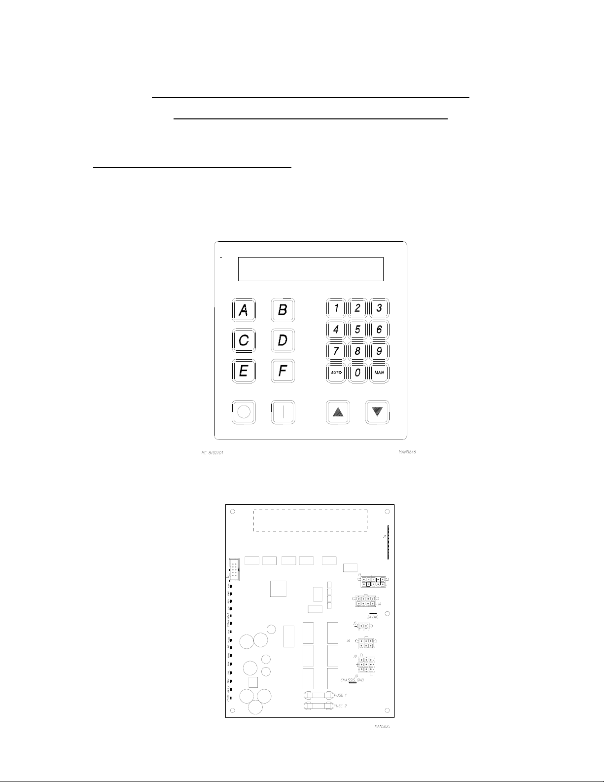
SECTION VII
PROCEDURE FOR FUNCTIONAL CHECK
OF REPLACEMENT COMPONENTS
1. Microprocessor Controller (Computer) Board
a. Upon completing installation of the replacement microprocessor controller (computer) board, reestablish
power to the dryer.
b. Start the drying cycle by pressing any of the preset cycles in letters A-F.
c. Verify that the applicable indicator lights on the back side of the microprocessor controller (computer)
board are lit. (Refer to the illustration below.)
43
Page 48
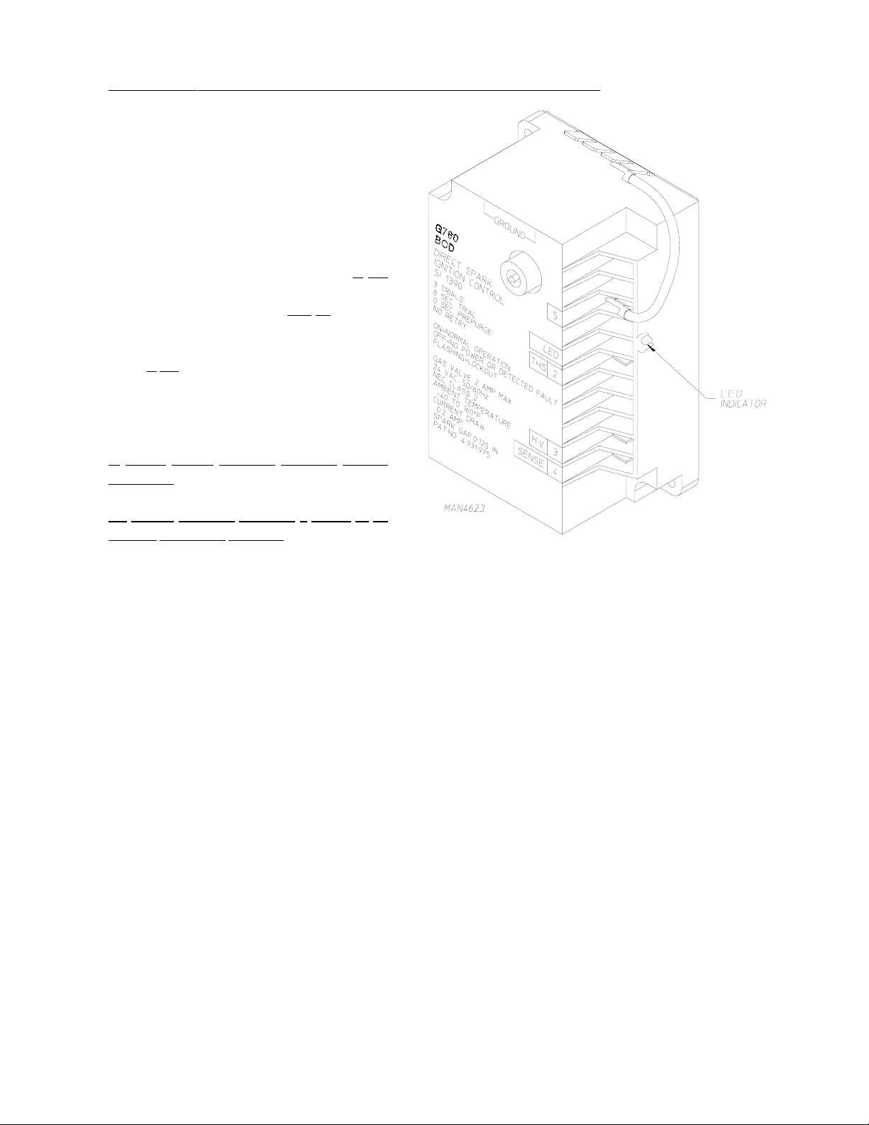
2. For Models With Johnson Controls Direct Spark Ignition (DSI) Module (G760)
Theory Of Operation:
Start the drying cycle. When the gas burner
ignites within the chosen trial for ignition time
(6-seconds), the flame sensor detects gas
burner flame and signals the DSI module to
keep the gas valve open...as long as there is a
call for heat. The DSI module will
“LOCKOUT” if the gas burner flame is not
sensed at the end of the trial for ignition period.
The trial for ignition period
for a total of two (2) retries/trials (the initial
try and two [2] more retries/trials). If the
is not sensed at the end of the third retry/
flame
trial (inter-purge period of 30-seconds) the DSI
module will “LOCKOUT” (light emitting diode
[L.E.D.] flashes).
A steady L.E.D. indicator indicates normal
operation.
will be repeated
No L.E.D. indicator indicates a power or an
internal failure has occurred.
44
Page 49
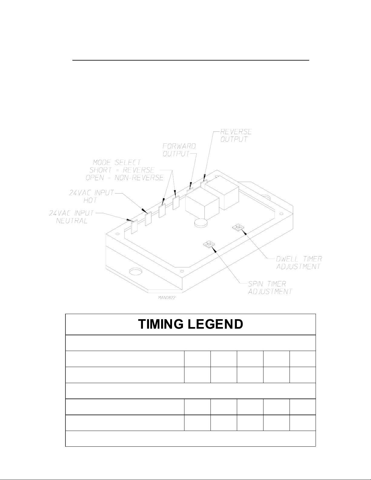
SECTION VIII
REVERSING TIMER SPIN/DWELL ADJUSTMENTS
Dual timer models with “reversing option” have an electric reversing timer in the electric service box, which is
located in the upper rear area of the dryer.
Both dwell (stop) time and basket (tumbler) spin time are adjustable by mode selection switches located on the
electronic timer (as noted in the illustration below).
SPIN TIME
Adjustment Position Number 1 2 3 4 5
Time in Seconds* 30 60 90 120 150
DWELL (STOP) TIME
Adjustment Position Number 1 2 3 4 5
Time i n Seconds* 5 6.3 7.6 8.9 10.2
* Values shown are +/- 1-second.
45
Page 50
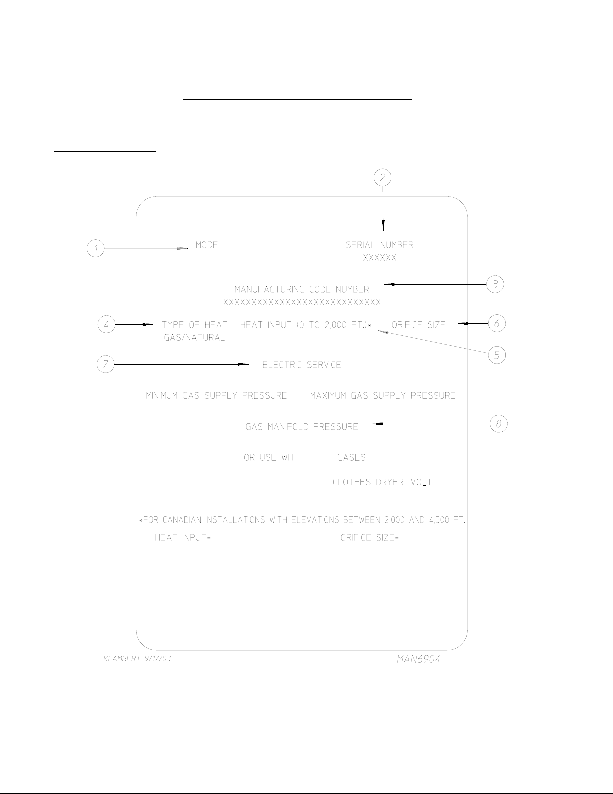
DATA LABEL INFORMATION
A. DATA LABEL
Contact American Dryer Corporation
SECTION IX
When contacting American Dryer Corporation certain information is required to insure proper service/parts
information from American Dryer Corporation. This information is on the data label located on the left side
panel/wall area behind the control door. When contacting American Dryer Corporation please have the
model number and serial number available.
46
Page 51

THE DATA LABEL
1. MODEL NUMBER
The model number is an ADC number, which describes the size of the dryer and the
type of heat (gas, electric, or steam).
2. SERIAL NUMBER
The serial number allows ADC to gather information on your particular dryer.
3. MANUFACTURING CODE NUMBER
The manufacturing code number is a number issued by ADC, which describes ALL
possible options on your particular model.
4. TYPE OF HEAT
This describes the type of heat for your particular dryer: gas (either natural gas or
liquid propane [L.P.] gas), electric, or steam.
5. HEAT INPUT (FOR GAS DRYERS)
This describes the heat input in British Thermal Units per Hour (Btu/hr).
6. ORIFICE SIZE (FOR GAS DRYERS)
Gives the number drill size used.
7. ELECTRIC SERVICE
This describes the electric service for your particular model.
8. GAS MANIFOLD PRESSURE (FOR GAS DRYERS)
This describes the manifold pressure taken at the gas valve tap.
47
Page 52
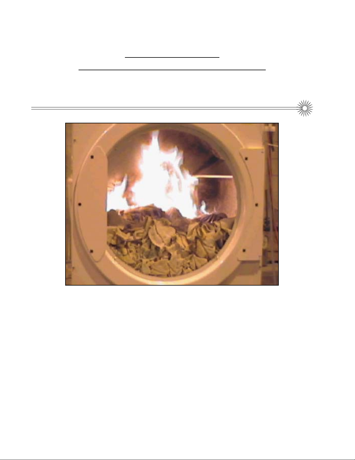
SECTION X
SENSOR ACTIVATED
FIRE EXTINGUISHING (S.A.F .E.) SYSTEM
S.A.F.E. System In Action
The exclusive Sensor Activated Fire Extinguishing (S.A.F.E.) System will extinguish fires
that may start in the drying basket (tumbler). A series of sensors positioned throughout
the basket (tumbler) and interfaced with the microprocessor will trigger the S.A.F.E.
system water jet(s) to quickly extinguish the flames. The water jet(s) remain on for 2
minutes and will automatically activate again if a fire condition remains or reignites. While
the water jet(s) are activated, the basket (tumbler) will jog to move the water throughout
the load. The microprocessor will display that the system was activated and will continue
to display until the dryer is attended to.
We have tried to make this manual as complete as possible and hope you will find it
useful. ADC reserves the right to make changes from time to time, without notice or
obligation, in prices, specifications, colors, and material, and to change or discontinue
models.
48
Page 53
BEFORE YOU START!
CHECK LOCAL CODES AND PERMITS
Call your local water company or the proper municipal authority for information regarding local codes.
IMPORTANT: It is your responsibility to have ALL plumbing connections made by a qualified
professional to ensure that the plumbing installation is adequate and conforms to local,
state, and federal regulations or codes.
IMPORTANT: It is the installation or owners responsibility to see that the necessary or required
water, water pressure, pipe size, or connections are provided. Manufacturer assumes
no responsibility if the Sensor Activated Fire Extinguishing (S.A.F .E.) System
is not
connected, installed, or maintained properly .
INSTALLATION
1. Requirements
The S.A.F .E. system must be supplied with a minimum water pipe size of 1/2” and be provided with 40 psi
+/- 20 psi (2.75 bar +/- 1.37 bar) of pressure. For use of optional manual bypass, a second source with the
same piping and pressure requirements is required.
Flexible 1/2” feeds must be provided to avoid damage to electric water solenoid valve by vibration.
IMPORTANT: Flexible supply line/coupling must be used. Solenoid valve failure due to hard
plumbing connections WILL VOID WARRANTY.
If the rear area of the dryer or the water supply is located in an area where it will be exposed to cold/
freezing temperatures, provisions must be made to protect these water lines from freezing.
WARNING: If the water in the supply line or water solenoid valve freezes, the S.A.F .E. system will
be INOPERATIVE!!
IMPORTANT: Appliance is to be connected to the water mains using a new hose-set and the old
hose-sets should not be reused.
49
Page 54
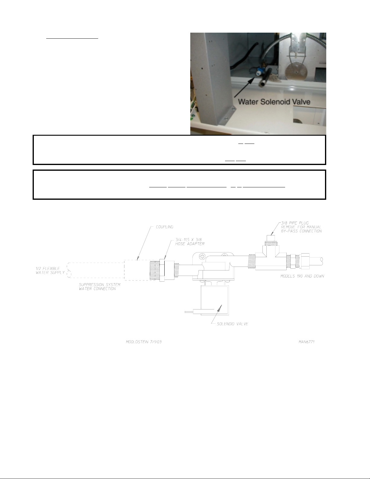
2. Water Connections:
The water connection is made to the 3/4”-11.5 NH
hose adapter of the electric water solenoid valve
located at the rear upper midsection of the dryer (refer
to the photo).
The water solenoid valve has a 3/8” M.P .T . connection
supplied with a 3/4”-11.5 NH hose adapter to provide
the minimum 1/2-inch supply (feed) line. Flexible
supply line/coupling must be used in an effort to
avoid damaging the electric water solenoid valve.
NOTE: The 3/4”-11.5 NH is a standard hose coupling screw thread. It is not to be confused with
3/4” N.P .T . The sealing of an NH connection is made with a washer opposed to the mating
threads of an N.P .T . assembly . The two (2) thread designs are not compatible.
IMPORTANT: Flexible supply line/coupling must be used. Solenoid valve failure due to hard
plumbing connections WILL VOID WARRANTY. It is recommended that a filter
or strainer be installed in the water supply line.
Typical water supply...
50
Page 55
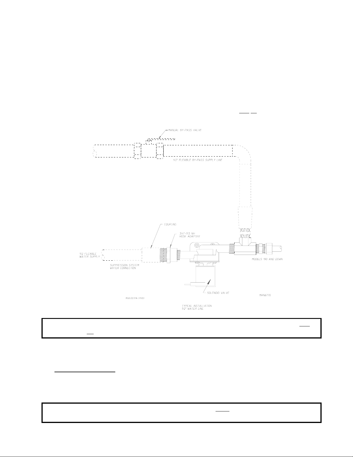
OPTIONAL MANUAL BYPASS
Provisions are made in the dryer Sensor Activated Fire Extinguishing (S.A.F.E.) system for the installation of an
optional manual bypass. Depending on the model dryer, the connections for the manual bypass are made at the
“T” or “four way” fitting located in the outlet supply side of the water solenoid valve. The use and connections
of this manual bypass are at the option or discretion of the owner.
The water connection for the manual bypass is made to the “T” or “four way” fitting which has a 3/8” F .P.T. and
a coupling must be used to provide the minimum 1/2” supply (feed) line.
If the rear area of the dryer or the water supply is located in an area where it
temperatures, provisions must be made to protect these water lines from freezing.
will be exposed to cold/freezing
WARNING: If the water in the supply line or water solenoid valve freezes, the S.A.F .E. system will
be INOPERA TIVE!!
The manual ball cock shutoff valve must be located outside of the dryer at a distance from the dryer where it
is easily accessible.
3. Electrical Requirements
No independent external power source or supply connection is necessary . The 24 volt power to operate the
S.A.F.E. system is accomplished internally in the dryer (from the dryer controls).
WARNING: Electrical power must be provided to the dryer at ALL times. If the main electrical
power supply to the dryer is disconnected, the S.A.F .E. system is INOPERA TIVE!!
51
Page 56

Sensor Activated Fire Extinguishing (S.A.F.E.) System
Theory of Operation
While the dryer is in an idle state, or 20-seconds after the heat turns off, the Phase 7 control monitors the
S.A.F .E. system probe located in the top of the basket (tumbler) chamber and records the minimum temperature.
If the minimum recorded S.A.F.E. system probe temperature is no less than 120° F (48° C) and the control
detects a 50° rise in temperature, this
While a drying cycle is in process and the heat has turned on at least once, the Phase 7 control monitors the
exhaust temperature transducer. If the drying cycle temperature set point is set greater than 160° F (71° C) and
the control detects an exhaust temperature rise 25° F greater than set point, this
S.A.F .E. system routine will activate. If set point is below 160° F (71° C), the trip point
Once the S.A.F .E. system routine is activated, water will be injected into the basket (tumbler) chamber. Anytime
water is being injected into the basket (tumbler), the basket (tumbler) drive will turn the load for 1-second every
15-seconds. This process will continue for a minimum of 2 minutes. After 2 minutes have elapsed, the control
will check if the temperature remained above trip point; if so water will remain on. The control will continue to
check if temperature is above trip point every 30-seconds. If the water has been on for a constant 10 minutes,
the water will be turned off regardless of the temperature. If the temperature has dropped below trip point, the
control will turn off the water prior to 10 minutes.
SYSTEM RESET
will be the trip point and the S.A.F.E. system routine will activate.
will be the trip point and the
will be 185° F (85° C).
After the microprocessor determines that the situation is under control and shuts the water being injected into the
basket (tumbler) off, the microprocessor display will read “S.A.F.E. System activated,” and the horn/tone will
sound until reset manually.
T o reset the microprocessor once the control displays “S.A.F.E. System activated,” press the red
keyboard (touch pad).
key on the
NON-COIN S.A.F.E. SYSTEM CHECK PROCEDURE
The operation of the water solenoid valve can be tested to ensure that the water supply system and valve are
functional. Before attempting system check, be sure that ALL water supply shutoff valves to the dryer are in
the OPEN position, and the dryer must be in the “READY” mode where no cycle is loaded or in progress.
The procedure is as follows:
1. Press and hold the RED STOP key (while in “READY” mode and no cycle in progress).
2. Press and hold the “A” key.
3. Water valve will open and water will be dispensed into basket (tumbler) area as long as both keys are held.
IMPORTANT: This is a test function only and the keys should be held and system activated for only
a second or so; otherwise, water will accumulate in various places in the dryer.
52
Page 57
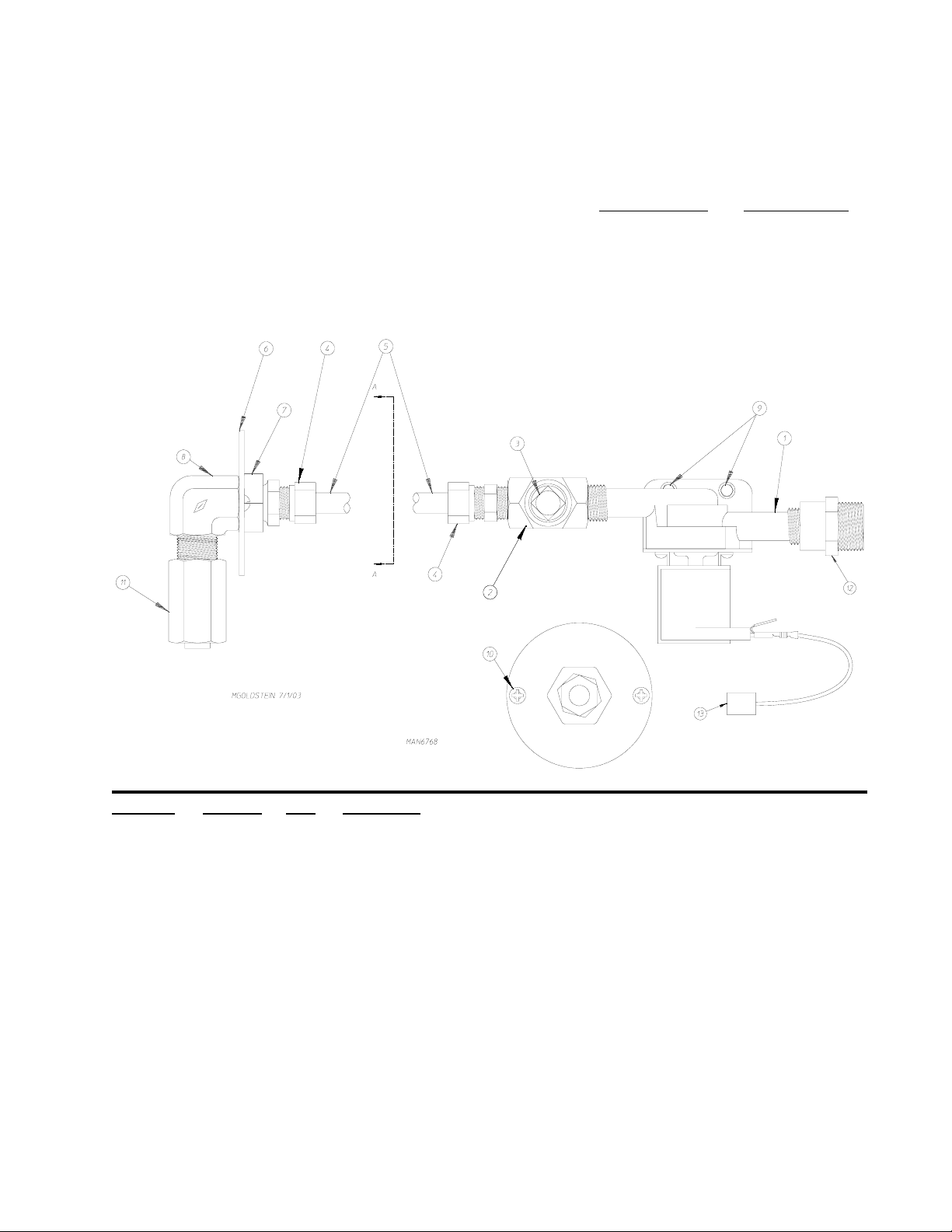
Sensor Activated Fire Extinguishing (S.A.F.E.) System
Parts Break Down
Replacement parts can be obtained from your reseller or the ADC factory. When ordering replacement parts
from the factory, you can FAX your order to ADC at (508) 678-9447 or telephone your order directly to the
ADC Parts Department at (508) 678-9000. Please specify the dryer model number and serial number in
addition to the description and part number, so that your order is processed accurately and promptly.
The illustrations on the following pages may not depict your particular dryer exactly. The illustrations are
composite of the various dryer models. Be sure to check the descriptions of the parts thoroughly before ordering.
Illus. No. Part No. Qty. Description
1 1651 14 1 S.A.F.E. System Solenoid Water Valve 24V 50/60 Hz
2 143220 1 3/8” F.P.T. Brass Te e
3 143251 1 3/8” M.P.T. Brass Plug
4 143208 2 3/8” Comp x 3/8” M.P.T. Brass Connector
5 143099* 6’ 3/8” OD x 0.035 W all Copper Tubing
6 31 1588 1 Sprinkler Head Mounting Plate
7 143303 1 3/8” N.P.T. Brass Locknut
8 143155 1 3/8” Brass Elbow 90°
9 150300 2 #10-16 x 1/2” Hex Washer TEK Screw
10 150301 2 #8-18 x 7/16” Phillips Pan Head TEK Screw
1 1 143581 1 3 GPM 3/8” F.P.T. Spray Nozzle
12 143025 1 3/4”-11.5 NH x 3/8” N.P.T. Hose Adapter
13 824081 1 R.C. Network Assembly
* Sold by the foot.
53
Page 58
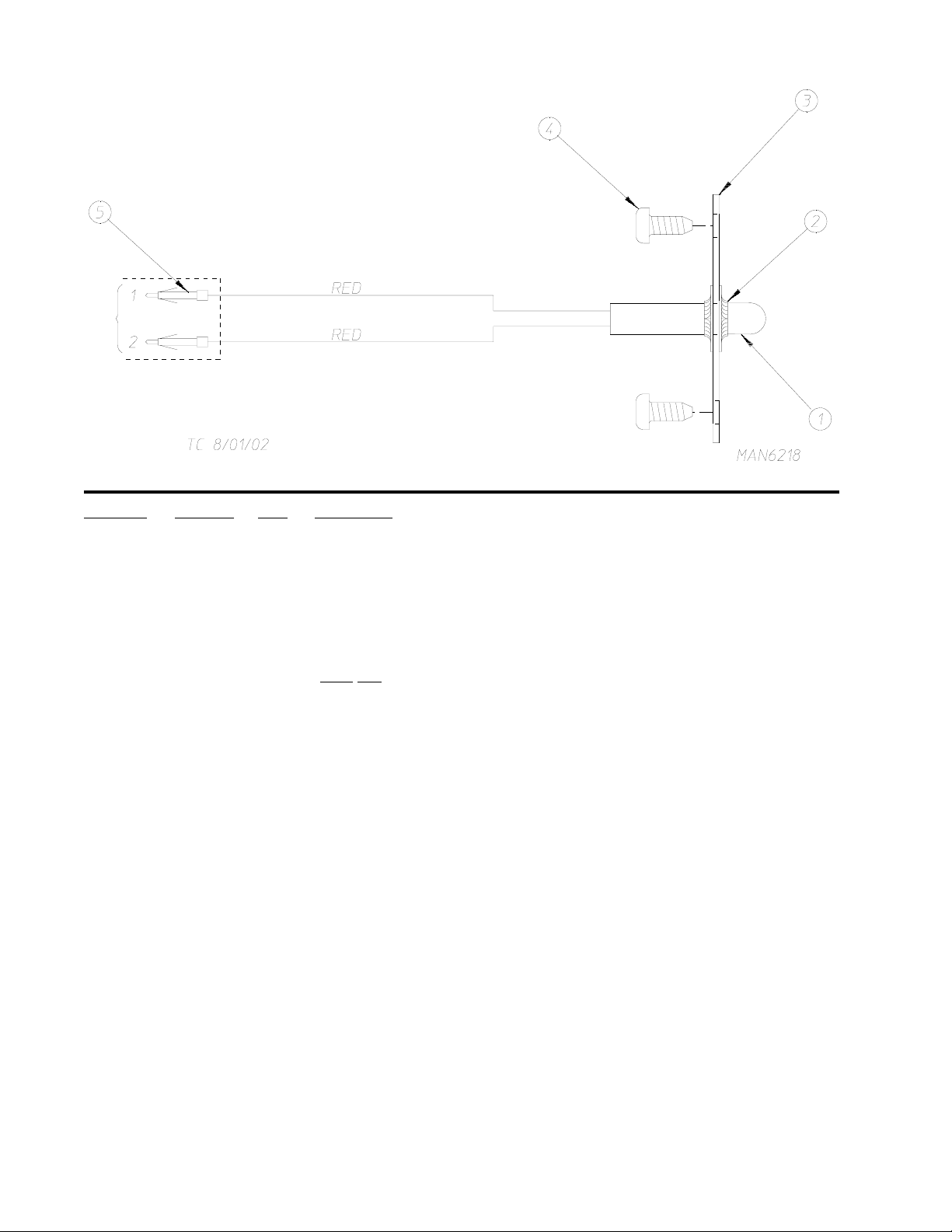
Illus. No. Part No. Qty. Description
1 822752 1 S.A.F.E. System Temperature Probe Assembly
(includes illus. nos. 1 through 5)
2 154007 2 Push On Fastener
3 390390 1 Sensor Bracket ONLY
4 150301 2 #8-18 x 7/16” Phillips Pan Head TEK Screw
5 122647 1 Connector ONLY
(does not include terminals)
54
Page 59

ADC 113381 1 - 08/07/02-25 2-08/12/02-50 3*02/21/03-50
4 * 04/25/03-50 5* 07/18/03-50 6*09/26/03-50
 Loading...