

Page 1
Megabit Modem
MODEL 400F
USER MANUAL
Catalog Number
MMD4076I1
Issue 1
Page 2

Copyright
January 2001
©Copyright 2001 ADC DSL Systems, Inc. All Rights Reserved.
Trademark Information
ADC is a registered trademark of ADC Telecommunications, Inc.
Megabit Modem is a registered trademark of ADC DSL Systems,Inc. All Rights Reserved Technologies, Inc. No right,
license, or interest to such trademarks is granted hereunder, and you agree that no such right, license, or interest shall
be asserted by you with respect to such trademark.
Other product names mentioned in this practice are used for identification purposes only and may be trademarks or
registered trademarks of their respective companies.
Disclaimer of Liability
Information contained in this document is company private to ADC DSL Systems, Inc., and shall notbe modified, used,
copied, reproduced or disclosed in whole or in part without the written consent of ADC.
Contents herein are current as of the date of publication. ADC reserves the right to change the contents without prior
notice. In no event shall ADC be liable for any damages resulting from loss of data, loss of use, or loss of profits, and
ADC further disclaims any and all liability for indirect,incidental, special, consequential orother similar damages. This
disclaimer of liability applies to all products, publications and services during and after the warranty period.
ii Megabit Modem 400F User Manual
Page 3

About this User Manual
ABOUT THIS USER MANUAL
Use this manual to install and configure the Megabit Modem 400F. This manual provides
instructions on:
• information you will need to configure the modems
• unpacking and inspecting the modems for installation
• installing the modems
• setting up parameters for your applications that will be used to configure the modems
• configuring system parameters
• configuring sessions between the modem and a service provider
• monitoring and troubleshooting the modems
Chapter 9 provides a technical reference for implementing data transmission in the Megabit
Modem 400F. The chapter covers information about Asymmetric Digital Subscriber Line
(ADSL), rate adaptive transmission, the bridging/routing operating mode, and Simple Network
Management Protocol (SNMP) management.
IP addresses used in this manual are for example only. You will acquire your own addresses
from your information services coordinator to configure the Megabit Modem 400F. You will,
however, use the IP address specified in “Accessing the 400F Web Pages” on page 23 to access
the Megabit Modem 400F from a Web browser.
DOCUMENT CONVENTIONS
Two types of messages, identified by icons, appear in the text.
Notes contain information about special circumstances.
Cautions indicate the possibility of equipment damage or the possibility of
personal injury.
Megabit Modem 400F User Manual iii
Page 4

Product Certifications
PRODUCT CERTIFICATIONS
FCC
This equipment has been tested and found to comply with the limits for a Class B digital device,
pursuant topart 15of theFCC Rules. Theselimits are designed toprovide reasonable protection
against harmful interferencein a residential installation. This equipment generates, uses and can
radiate radio frequency energy and,if not installed and used in accordance with the instructions,
may cause harmful interference to radio communications. However, there is no guarantee that
interference will not occur in a particular installation.
If this equipment does cause harmful interference to radio or television reception, which can be
determined by turning the equipment off and on, the user is encouraged to try to correct the
interference by one or more of the following measures:
• Reorient or relocate the receiving antenna.
• Increase the separation between the equipment and receiver.
• Connect the equipment into an outlet on a circuit different from that to which the receiver
is connected.
• Consult the dealer or an experienced radio/TV technician for help.
UL
The Megabit Modem 400F meets all safety requirements per UL-1950 and cUL standards.
CE
The Megabit Modem 400F meets all EMC and safety requirements per EN 300 386-02 and
IEC 950.
iv Megabit Modem 400F User Manual
Page 5

Table of Contents
TABLE OF CONTENTS
Chapter 1: About The Product _______________________________________________1
Features................................................................................................................................2
Applications.........................................................................................................................3
Connection Between a Remote Office and a Central Site ....................................3
Internet Access for Larger LANs..........................................................................4
Chapter 2: What You Need To Start __________________________________________5
Verify Package Contents .....................................................................................................5
Requirements For Your System ..........................................................................................6
Requirements For The Installation Site...............................................................................6
Location for Modem Installation ..........................................................................6
Phone Service........................................................................................................9
What You Need from Your Service Provider .....................................................................9
What You Will Choose .....................................................................................................10
Configuration ......................................................................................................10
Power Cable ........................................................................................................10
Chapter 3: Installing the Modem ____________________________________________11
Attaching the Feet..............................................................................................................12
Setting the MDI/MDI-X Switch........................................................................................13
Installing Cabling ..............................................................................................................14
Setting Up ADSL Service .................................................................................................15
Checking LED Indications ................................................................................................15
Connecting Phone Service.................................................................................................16
Chapter 4: Setting Up For Configuration _____________________________________17
Setting Up the PC To Configure the Modem....................................................................18
Configuring a Web Browser..............................................................................................19
Set the Web Page Update Frequency ................................................................................21
Accessing the 400F Web Pages.........................................................................................23
Megabit Modem 400F User Manual v
Page 6

Table of Contents
Saving the Configuration...................................................................................................24
Saving the Configuration to NVRAM.................................................................25
Resetting the Modem to Factory Defaults...........................................................26
Resetting the Modem...........................................................................................28
Chapter 5: Configuring System Settings ______________________________________29
Defining TFTP Parameters ................................................................................................30
Defining SNMP Parameters...............................................................................................31
Setting the Time and Date .................................................................................................33
Configuring System Security.............................................................................................34
Chapter 6: Configuring Sessions_____________________________________________35
Selecting a Configuration Model.......................................................................................36
Configuring RFC 1483 Bridging/Routing Sessions ..........................................................37
Configuring the WAN for RFC 1483 Bridge/Routing........................................38
Configuring the LAN for RFC 1483 Bridge/Routing .........................................41
Activating and Deactivating Sessions................................................................................46
Activating Sessions .............................................................................................46
Deactivating Sessions..........................................................................................47
Chapter 7: Viewing Statistics________________________________________________49
Viewing ADSL Status .......................................................................................................49
Viewing Network Statistics ...............................................................................................52
LAN Statistics .....................................................................................................52
WAN Statistics....................................................................................................54
Chapter 8: Maintenance and Troubleshooting _________________________________55
Maintenance.......................................................................................................................55
Updating Software...............................................................................................55
Using the RS-232 Management Port...................................................................57
Setting Up the PC to Request an IP Address.....................................................................59
Troubleshooting.................................................................................................................60
vi Megabit Modem 400F User Manual
Page 7

Table of Contents
Chapter 9: Technical Reference _____________________________________________61
ADSL.................................................................................................................................61
ATM ..................................................................................................................................61
Rate Adaptive Transmission..............................................................................................63
Rate Adaptation...................................................................................................63
Reach, Data Rate, SNR Margin, and Noise Environment ..................................63
Bridging and Routing ........................................................................................................64
Bridging...............................................................................................................64
Routing................................................................................................................66
Encapsulation for RFC 1483 Bridging/Routing..................................................66
Management Protocols ......................................................................................................67
SNMP..................................................................................................................67
MIBs and Traps...................................................................................................68
DNS Resolution.................................................................................................................68
TFTP Server ......................................................................................................................68
Appendix A: Specifications and Data _________________________________________69
WAN Interface Specifications...........................................................................................69
Encapsulation ....................................................................................................................70
LAN Interface....................................................................................................................71
Physical Specifications......................................................................................................71
Power Supply.....................................................................................................................71
Environmental ...................................................................................................................71
Compliance........................................................................................................................72
RFCs ..................................................................................................................................72
MIBs ..................................................................................................................................72
Rate vs. Reach ...................................................................................................................73
Hardware ...........................................................................................................................74
Installation Kit.....................................................................................................74
Connector Pinouts...............................................................................................75
Megabit Modem 400F User Manual vii
Page 8

Table of Contents
Appendix B: Technical Assistance and Warranty _______________________________77
Technical Support..............................................................................................................77
World-Wide Web...............................................................................................................77
Limited Warranty...............................................................................................................78
Advance Replacement .......................................................................................................79
Billing ................................................................................................................................79
Returning a Product ...........................................................................................................80
Appendix C: Configuration Worksheets_______________________________________83
Configuration Information.................................................................................................83
System Mode Worksheet ....................................................................................84
WAN Configuration Worksheet .........................................................................85
Login Name / Login Password Worksheet .........................................................87
Fixed IP Addresses Worksheet ...........................................................................89
Appendix D: Glossary ______________________________________________________91
Index____________________________________________________________________97
viii Megabit Modem 400F User Manual
Page 9

ABOUT THE PRODUCT
1
You have purchased the ADC Megabit Modem 400F that
connects your Ethernet LAN to service providers for
instant and high-speed access to the Internet or to other
types of Wide Area Network (WAN) applications.
The modem provides this service over a single-pair
telephone line with downstream ADSL transmission up
to 7.552 Mbps. The upstream ADSL transmission is up
PWR
MEGABITMODEM 420F
LINK
LAN
TX
RX
COL
SYNC
ADSL
TX RX MAR
to 928 kbps. You can also receive telephone service over
the same single-pair line as your data.
The Megabit Modem 400F uses ATM over DMT ADSL technology to provide this high-speed
transmission between the modem and the service provider. Asynchronous Transfer Mode
(ATM) provides transmission of fixed-size cells over preestablished connections for a network
interface that is predetermined and always in place. The Asymmetric Digital Subscriber Line
(ADSL) provides rate-adaptive transmission which means that the service provider can deliver
the best possible transmission rate to you based on distance and line conditions, in addition to
providing phone service to you over the same single-pair line.
The Megabit Modem 400F is easy to install and configure. To install the modem:
• connect a telephone cable from the modem to a wall phone jack for ADSL service
• connect a cable from the modem to a PC or an Ethernet hub for LAN service
• connect a power cable to a local power source
To configure the modem, launch a Web browser on your PC and load the Megabit Modem
Configuration and Management Tool Web pages that guide you through configuration. Use
the Web page called EasySession™ to configure up to 32 simultaneous sessions with service
providers. You can also configure other system parametersand monitor ADSL, LAN, and other
networking functions using the Web pages.
LEDs on the modem front panel provide continual status at-a-glance for network and modem
connections.
Megabit Modem 400F User Manual 1
Page 10

Features
FEATURES
The Megabit Modem 400F provides:
• rate-adaptable ADSL transmission downstream at up to 7.552 Mbps and upstream at
up to 928 kbps
• Internet or other types of WAN applications and phone service over your existing
phone line
• Bridging/routing protocol RFC 1483 encapsulation method
• Dynamic Host Configuration Protocol (DHCP) server to provide network configuration
information including IP addresses to LAN devices
• TFTP to download software
• AccessGain™ software thatprovides access through an HTTPserver to configure, manage,
and monitor the modem through a Web-based interface
• SNMP agent for management through any industry standard SNMP platform
• autosensing 10/100BASE-T Ethernet port for connection to the LAN
• DSLview™ LEDs that provide continual status at-a-glance for power, LAN, and
ADSL connections
• ATM technology with 32 virtual channels allowing 32 simultaneous sessions
Chapter 9, “TechnicalReference” on page 61 provides more information about the technologies
implemented in the Megabit Modem 400F.
2 Megabit Modem 400F User Manual
Page 11
Chapter 1: About The Product
APPLICATIONS
The Megabit Modem 400F provides a practical solution for many networking applications.
The following illustrations show some of the many possible solutions when using the Megabit
Modem 400F.
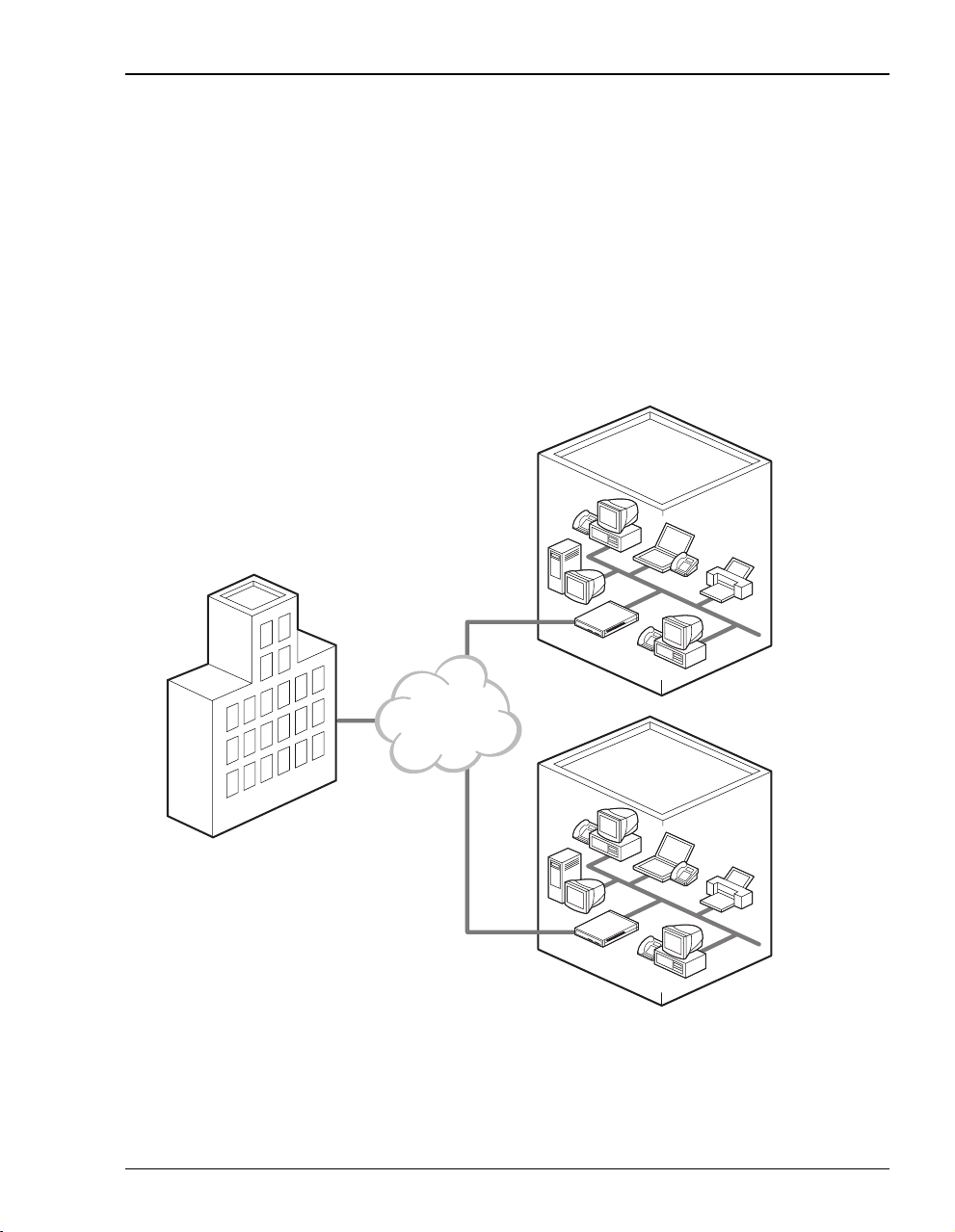
Connection Between a Remote Office and a Central Site
You can connect remote offices to a corporate office network.
Corporate office
400F
Provider
network
400F
Megabit Modem 400F User Manual 3
Remote offices
Page 12
Applications
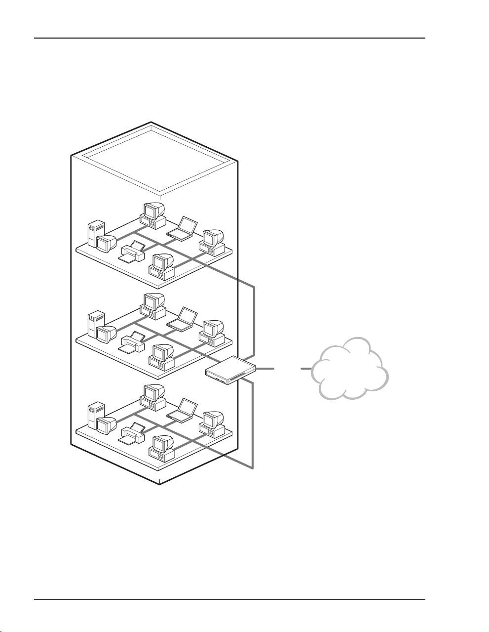
Internet Access for Larger LANs
You can connect businesses with large LANs to the Internet.
ADSL
400F
4 Megabit Modem 400F User Manual
Internet
Page 13
WHAT YOU NEED TO START
This chapter identifies the preparations and prerequisites for installing the Megabit Modem
400F. To install the modem, verify that:
• the contents of the package are accurate as described on this page
• your system meets requirements for connecting to and configuring the modem
(see “Requirements For Your System” on page 6)
• your facility meets installation site requirements (see “Requirements For The Installation
Site” on page 6)
• the configuration parameters are available from your service provider (see “What You
Need from Your Service Provider” on page 9)
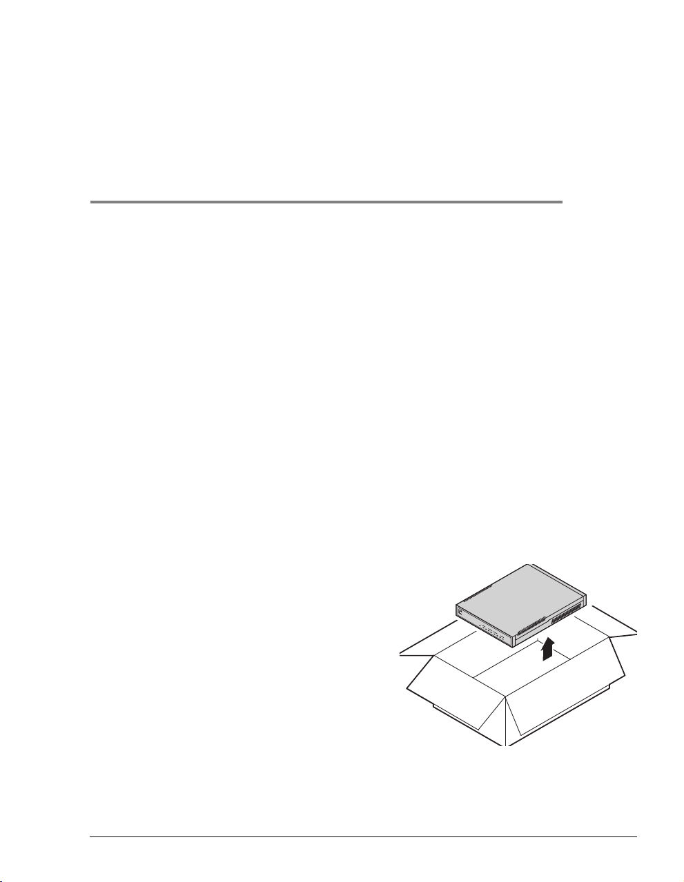
VERIFY PACKAGE CONTENTS
As you unpack the Megabit Modem 400F, visually inspect the container for signs of damage.
If the equipment was damaged in transit, report the damage to the transportation company and
to the sales representative.
Check the contents of the package for the Megabit
Modem 400F and the following:
2
• one black cable
• onegreyphonecord
PWR
LINK
M
LAN
E
TX
G
A
RX
B
I
COL
T
M
SYNC
O
D
ADSL
E
TX RX
M
4
2
MAR
0
F
• four rubber, self-adhesive feet
• two screws
• power supply and optional power cord
(see “Power Cable” on page 10 for options)
• grey cable and DB-9 console port adapter
If you need to store the modem for a prolonged period, store it in the original antistatic bag
and packaging. Observe environmental specifications as stated on page 69.
Megabit Modem 400F User Manual 5
Page 14

Requirements For Your System
REQUIREMENTS FOR YOUR SYSTEM
You need the following hardware and software to complete the installation and configuration of
the Megabit Modem 400F:
• PC with an Ethernet Network Interface Card (NIC)
• TCP/IP network protocol stack (see your documentation for your operating system)
• Web browser installed such as Netscape
• Ethernet hub (optional)
®
or Internet Explorer®Version 4.0 or higher
REQUIREMENTS FOR THE INSTALLATION SITE
To install the Megabit Modem 400F:
• select a location to install the modems as described in the section “Location for Modem
Installation” on this page
• identify requirements to connect phones, if you get phone service, as described in the
section “Phone Service” on page 9
Location for Modem Installation
You can install the modem either:
• placed on a flat surface (shown on page 7)
• mounted on a wall (shown on page 8)
Your facility must have the following minimum site requirements to install each modem:
• power outlet
• RJ-11 wall jack that has DMT ADSL service available
6 Megabit Modem 400F User Manual
Page 15
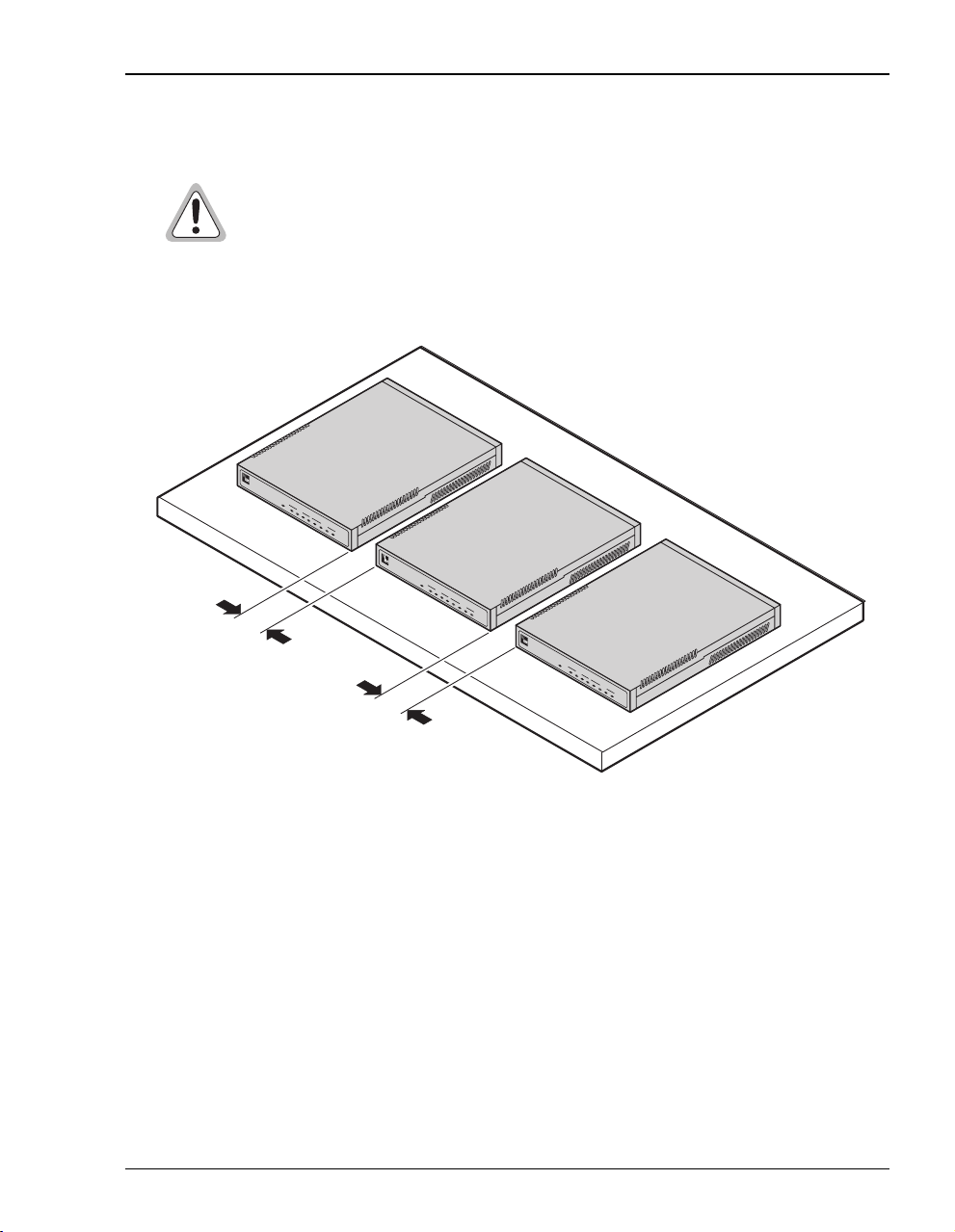
Flat-Surface Mount
Do not stack the modems when installing ona flat surface. Themodems do not
dissipate heat properly when stacked.
Place the modems on a flat surface, such as on a table or in a rack.
PWR
LINK TX
M
E
LAN
G
A
RX
B
I
T
COL
M
SYNC
O
D
ADSL
E
TX RX MAR
M
4
2
0
F
PWR
LINK TX
M
E
LAN
G
A
RX
B
I
T
COL
M
SYNC
O
D
ADSL
E
TX RX MAR
M
4
2
0
F
Minimum
1-inch clearance
Minimum
1-inch clearance
PWR
M
LINK TX
E
G
LAN
A
B
RX
I
T
COL
M
O
SYNC
D
E
ADSL
M
TX RX MAR
4
2
0
F
Chapter 2: What You Need To Start
Megabit Modem 400F User Manual 7
Page 16
Requirements For The Installation Site
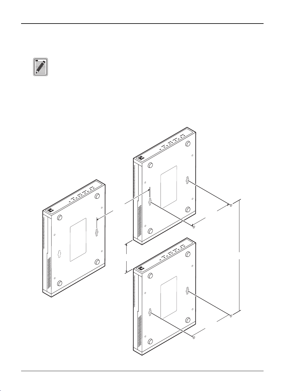
Wall Mount
Ensure the minimum dimensions (shown in the illustration) for spacing
between modems are met to allow for heat dissipation, viewing of front panel
LEDs, and cabling.
Mount the modems on a wall using the hardware included in the installation kit. Observe the
minimum dimensions between multiple modems (shown in the illustration) to ensure sufficient
ventilation for heat dissipation.
F
0
2
4
M
E
D
O
M
ADSL
T
I
TX RX MAR
B
A
SYNC
G
E
COL
M
LAN
TX RX
PWR LINK
F
0
2
4
M
E
D
O
M
ADSL
T
I
TX RX MAR
B
A
SYNC
G
E
COL
M
RX
LAN
LINK TX
PWR
3" to 4"
4.85"
F
0
2
4
M
E
D
O
M
ADSL
T
I
TX RX MAR
B
A
SYNC
G
E
COL
M
Min. 3"
PWR LINK TX RX
LAN
12"
4.85"
8 Megabit Modem 400F User Manual
Page 17

Chapter 2: What You Need To Start
Phone Service
If you get phone service with your data service, you need the following:
• A POTS splitter, or micro filter may be required; check with your service provider
• RJ-11 phone jacks for phone service
The POTS splitter is a device that separates data transmission from phone service. After
installing the POTS splitter, connect separate jacks for data from your session and for phone
service. Ensure that your service provider indicates which jacksare for dataand which jacks are
for phone service.
WHAT YOU NEED FROM YOUR SERVICE PROVIDER
This section lists the information you need to configure system settings and sessions for the
modem. Contact your service provider for this information. Use the worksheets, provided in
Appendix C on page 83, torecord yourconfiguration information. When you beginto configure
the modem in Chapter 4 on page 17, the procedures refer you to the proper table for the
configuration information that you recorded.
1 System mode (WAN connection for the sessions between the modem and the service
provider) utilizes Bridge/Router RFC 1483 protocol.
• Configure as a Bridge only, as a Router only, or as a Bridge and Router.
• Choose LLC or VC-MUX encapsulation.
• If Router, choose version of and direction for RIP (RIP1, RIP2, or RIP1 compatible).
• If Bridge, select whether or not to enable Spanning Tree.
2 Session address for Ports 1 through 32 (WAN configuration):
• ATM VPI and ATM VCI (specified for each session)
• IP address specified for each session by the service provider
For more information about the configuration choices listed above, see Chapter 9, “Technical
Reference” on page 61.
Megabit Modem 400F User Manual 9
Page 18

What You Will Choose
WHAT YOU WILL CHOOSE
Before configuring the modem, consider the options in the “Configuration” section, below.
Also, ensure that you have the appropriate power cable for your facility as described below in
the section “Power Cable.”
Configuration
You can choose to use:
• Domain Name System (DNS) resolution. You must specify the IP address for a device to
serve as the DNS resolver. You can also specify a second IP address to designate another
device to serve as a secondary DNS resolver. The DNS device maps human-readable
addresses to IP addresses. For more information about DNS resolution, see “DNS
Resolution” on page 68.
• TFTP server for downloading software updates to the modem. You specify the IP address,
subnet mask, and directory path (where software updates are located) for the device that
will be the TFTP server.
Power Cable
The Megabit Modem400F is available with a variety of power supplies and power cords. When
you order your modem, indicate which power option you need:
• a power supply for International use that does not include a power cord.
• a power supply for North American use that includes a North American power cord.
• a Universal power supply that includes a European power cord.
• a Universal power supply that includes a UK/Ireland power cord.
10 Megabit Modem 400F User Manual
Page 19

INSTALLING THE MODEM
The Megabit Modem 400F is easy to install:
• attaching adhesive-backed feet
• setting the MDI/MDI-X switch
• connecting a cable from the modem to a PC or an Ethernet hub for LAN service
• connecting a phone cord from the modem to a wall phone jack for DMT ADSL Internet
or other types of WAN services
• connecting a power cable to a local power outlet
Perform the installation on the following pages (see “Location for Modem Installation” on
page 6 to determine where to place modems). Use the parts listed below in the installation
procedures.
Part Function
Installation Kit
Rubber feet (four) Attaches to the base of the modem.
Black cable Connects the modem 10/100BASE-T connector to the LAN through a hub
or to a PC NIC.
Grey phone cord Connects the modem ADSL connector to the RJ-11 wall jack with DMT
ADSL service for access to the Internet or other types of WAN applcations.
Power cable Connects the modem POWER connector to the local power source. Power
supply optionally has a power cord. (See “Power Cable” on page 10 for
selection options.)
3
Not In Installation Kit (in ship box)
Grey cable and
adapter
Megabit Modem 400F User Manual 11
Connects the RS-232 MGMT port to an ASCII terminal or a PC running
terminal emulation software. Adapter assembly connects to a DB-9
connector on the PC. Then, one RJ-45 connector installs in the adapter and
the other connector into the console port on the modem.
Page 20
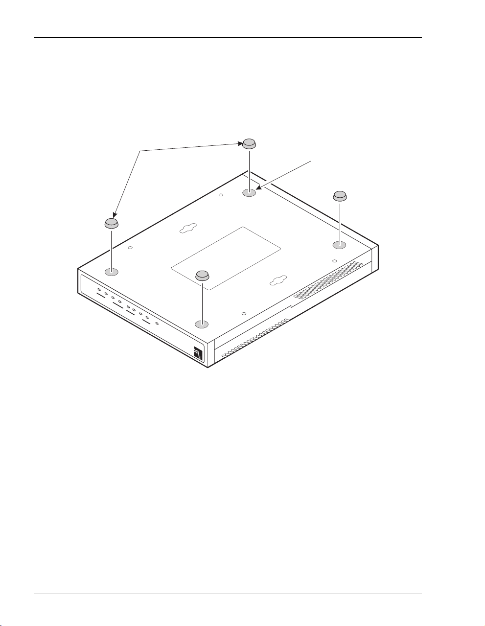
Attaching the Feet
ATTACHING THE FEET
Attach each of the four adhesive-backed rubber feet to a footprint recess on the bottom of
the modem.
Rubber feet
Recess
F
0
2
4
M
E
TX RX MAR
ADSL
D
O
SYNC
M
IT
COL
B
A
G
E
LAN
M
PWR LINK TX RX
12 Megabit Modem 400F User Manual
Page 21
Chapter 3: Installing the Modem
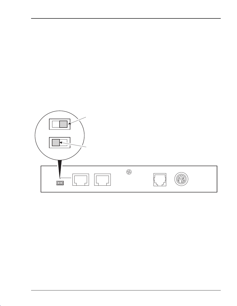
SETTING THE MDI/MDI-X SWITCH
Using the MDI/MDI-X switch, the Megabit Modem 400F can communicate with a device on
the LAN that is either MDI or MDI-X without having to change the cable (a straight-through
cable is supplied with the installation kit).
Set the switch for the 10/100BASE-T port to either:
• MDI-X when you are connecting to a device with an MDI port such as a PC with an
Ethernet NIC
• MDI when you are connecting to a device with an MDI-X port such as a hub, repeater,
bridge, or router
For connection to
devices such as
a PC
MDI-X
For connection to
MDI
devices such as
a hub
10BASE-T RS232 MGMTMDI MDI-X
Megabit Modem 400F User Manual 13
DSL POWER
Page 22
Installing Cabling
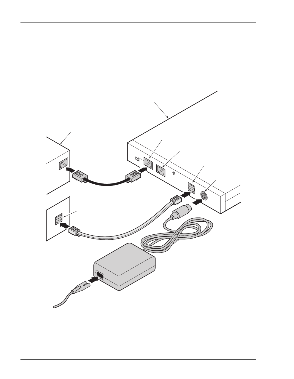
INSTALLING CABLING
Install the black cable for the 10/100BASE-T LAN connection, grey phone cord for the ADSL
port WAN connection, and the power cable to the power connector (power cable specified on
page 11).
.
Megabit Modem 700F
PC, hub or other
network device
10BASE-T port
RS-232 MGMT port
To p o w e r
outlet
Wall jack with DMT ADSL
service
MDI MDI-X
10BASE-T
RS232 MGMT
D
SL
ADSL port
POW
ER
Powe r
connector
If you need pinouts for the ADSL and 10/100BASE-T connectors, see “Connector Pinouts” on
page 75. For information on how to use the RS-232 management port for maintenance, see
“Using the RS-232 Management Port” on page 57.
14 Megabit Modem 400F User Manual
Page 23

Chapter 3: Installing the Modem
SETTING UP ADSL SERVICE
The service provider sets up the ADSL parameters for your service. The modem must have
the ADSL SYNC LED lit before you can connect sessions with your service provider. Verify
SYNC in the following section, “Checking LED Indications.”
CHECKING LED INDICATIONS
The section below describes LED indications for all operational modes. LEDs on the modem
front panel provide continual status at-a-glance for network and modem connections.
LED State Description
PWR On green Modem has power.
Off Modem does not have power.
LAN
LINK On green A PC, hub, or other network device is connected to the modem
Off No device is connected to the modem 10/100BASE-T interface.
TX Flashing green Modem is transmitting data to devices on the LAN.
Off Modem is not transmitting data to the LAN.
RX Flashing green Modem is receiving data from devices on the LAN.
Off Modem is not receiving data from the LAN.
COL Flashing green Collision detected on the 10/100BASE-T port..
Off No collisons detected.
SYNC On green ADSL transceiver is synchronized and in normal operation mode.
Flashing green ADSL transceiver is in a start-up sequence.
Off ADSL transceiver is not synchronized or is in a mode other than
TX Flashing green Modem is transmitting data to the service provider.
Off Modem is not transmitting data to the service provider.
RX Flashing green Modem is receiving data from the service provider.
Off Modem is not receiving data from the service provider.
MAR On green ADSL margin is at or above the value set by the service provider.
Off ADSL margin is below the value set by the service provider.
10/100BASE-T interface.
ADSL
normal operation or startup.
Megabit Modem 400F User Manual 15
Page 24

Connecting Phone Service
CONNECTING PHONE SERVICE
The service provider will supply a POTS splitter that separates the data transmission from
phone service. You will have one or more jacks for phone service and one jack for ADSL data
service. Connect your phones to the jacks indicated by the service provider for phone service.
16 Megabit Modem 400F User Manual
Page 25
SETTING UP FOR CONFIGURATION
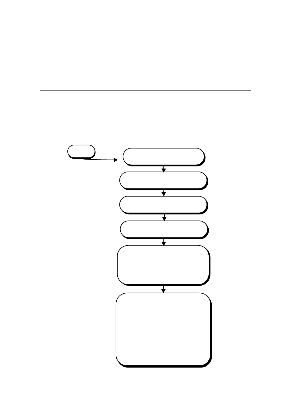
Set up a PC and a Web browser to configure the Megabit Modem 400F. This chapter provides
the set up procedures, then shows you how to access and navigate the Megabit Modem 400F
Web pages. The configuration process flow is shown below.
4
START
SettingUpthePCToConfigure
the Modem
ConfiguringaWebBrowser
Set the Web Page Update
Frequency
Accessing the 400F Web Pages
Configuring System Settings
• Defining TFTP Parameters
• Defining SNMP Parameters
• Setting the Time and Date
• Configuring System Security
Configuring RFC 1483
Bridging/Routing Sessions
• Configuring the WAN for RFC
1483 Bridge/Routing
• Configuring the LAN for RFC 1483
Bridge/Routing
• Defining or Modifying Static MAC
Entries
• Defining Static Route Entries
• Activating and Deactivating
Sessions
Page 18
Page 19
Page 21
Page 23
Chapter 5 Page 29
Chapter 6 Page 37
Megabit Modem 400F User Manual 17
Page 26
Setting Up the PC To Configure the Modem
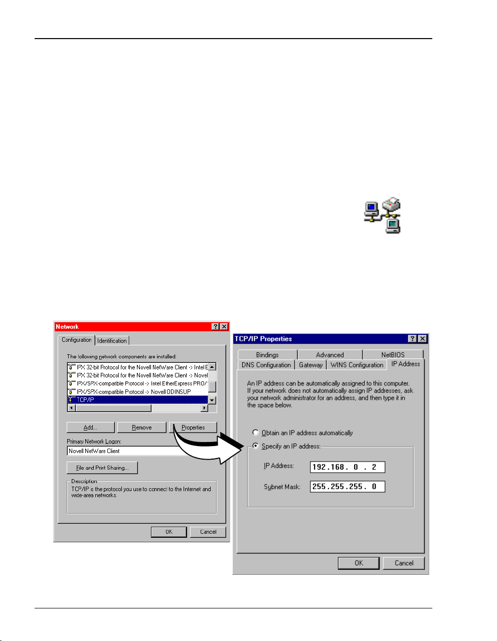
SETTING UPTHEPC TO CONFIGURE THE MODEM
Configure the Megabit Modem 400F using a PC connected to the 10/100BASE-T port. The PC
must be setto
card that is on the same subnet as the IP address for the modem. If you want to view or change
the default IP address for the modem, see “Using the RS-232 Management Port” on page 57.
The following is an example of how to set up the PC using Microsoft Windows
use an operating system other than Windows 95, refer to the appropriate operating system user
documentation.
Specify an IP address to initially access the modem. Enter an IP address for PC NIC
®
95. If you
1 Open the
Control Panel window and double-click on the Network icon
shown at right.
2 In the Network dialog (shown below), double-click TCP/IP under the
Configuration tab (or highlight TCP/IP then click Properties).
3 In the
IP Address tab, select Specify an IP address.
4 Enter an IP address and subnet mask for the PC, then click OK.
5 Restart the PC.
18 Megabit Modem 400F User Manual
Page 27
Chapter 4: Setting Up For Configuration
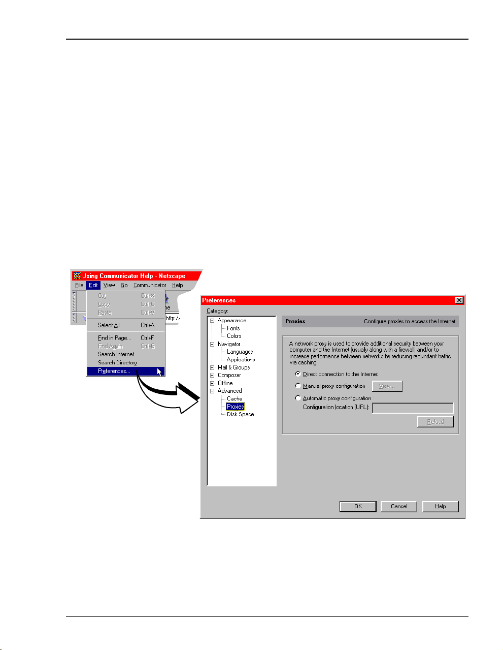
CONFIGURING A WEB BROWSER
Access the Megabit Modem 400F Web pages through a Web browser (see Page 6 for
Web browser versions supported). The Web browser must have the Proxies disabled.
Change the Proxies for your Web browser.
The procedures include steps for both Netscape and Internet Explorer Web browsers.
Disable the Proxies for Netscape:
1 Open a Web browser.
2 Select
3 Select
4
5 .
Edit, Preferences, Proxies.
Direct connection to the Internet, then click OK.
Megabit Modem 400F User Manual 19
Page 28
Configuring a Web Browser
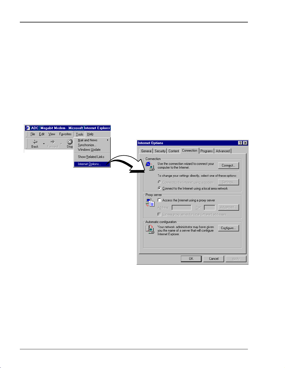
Disable the Proxies for Internet Explorer (version 5.0.0) :
1 Open the Web browser.
Select
Tools, Internet Options,andtheConnection tab.
If you have a version of Internet Explorer earlier than 5.0.0,
Internet Options may be found under the View options.
2 Select
Connect to the Internet using a local area network.
3 Ensure Access the Internet using a proxy server is not selected.
4 Click
.
OK.
20 Megabit Modem 400F User Manual
Page 29
Chapter 4: Setting Up For Configuration
SET THE WEB PAGE UPDATE FREQUENCY
Set the update frequency on the Web browser so that you are viewing current rather than cached
Web pages for the modem.
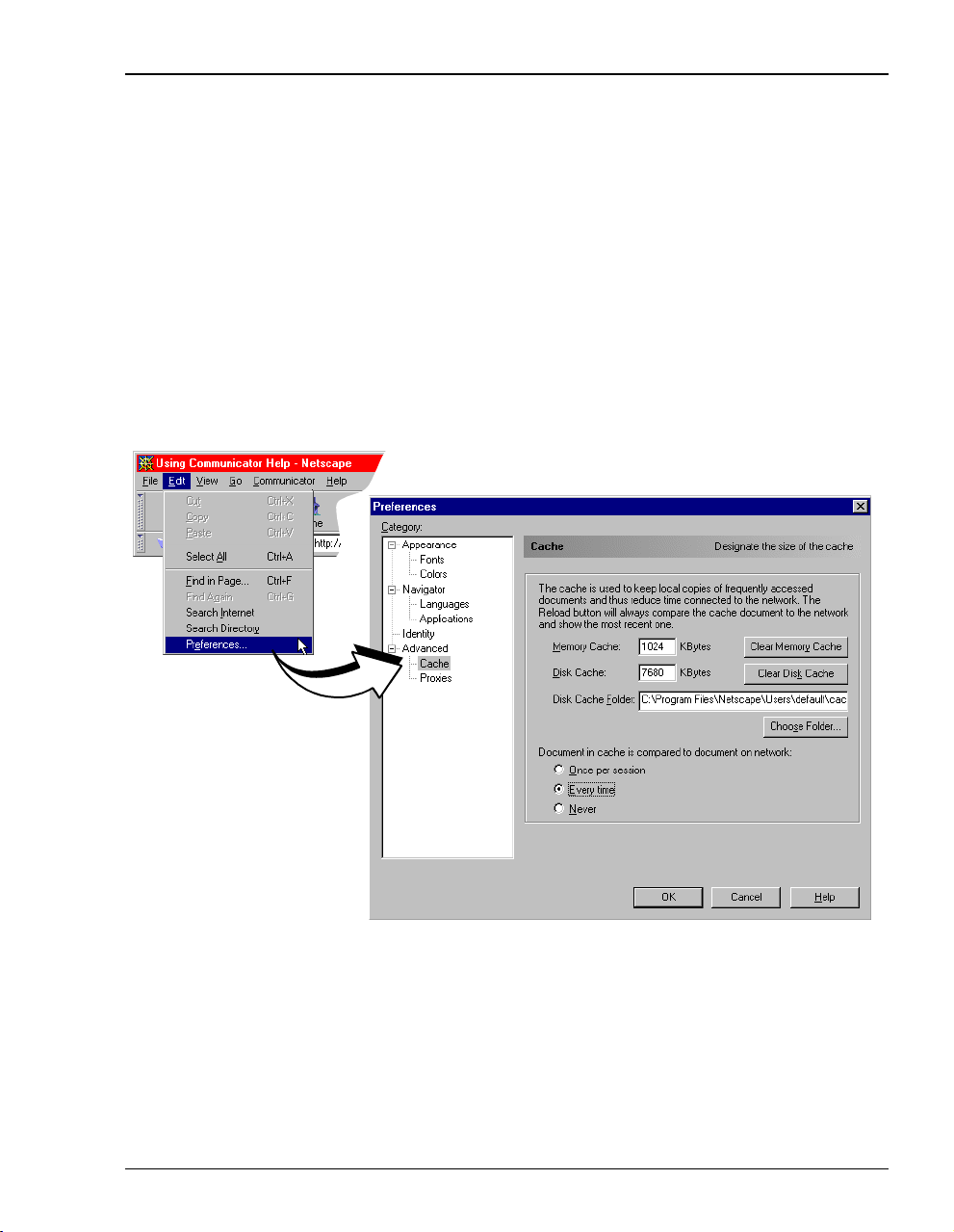
Set the Netscape Web page for update frequency:
1 Open the Web browser.
2 Select
3 Select
4 Click OK.
.
Edit, Preferences, Cache.
Every time under Document in cache is compared to document on network:.
Megabit Modem 400F User Manual 21
Page 30
Set the Web Page Update Frequency
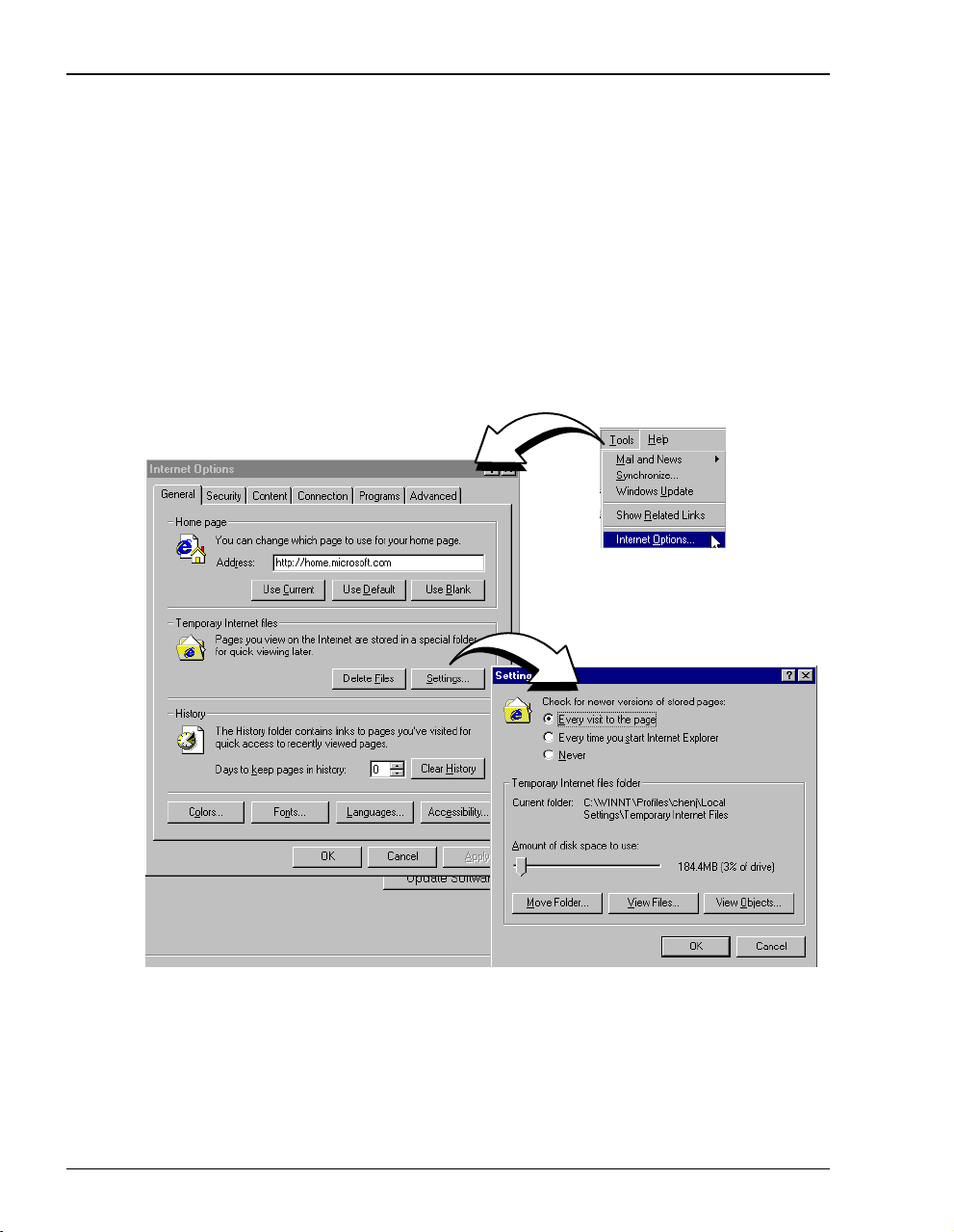
Set the Internet Explorer (version 5.0.0) Web page for update frequency:
1 Open the Internet Explorer Web browser.
2 Select
3 Select
4 Select
5 Click OK.
.
Tools,thenInternet Options.
If you have a version of Internet Explorer earlier than 5.0.0,
under the
View options.
Settings under the General tab in the Temporary Internet files box.
Every visit to the page under Check for newer versions of stored pages.
Internet Options may be found
22 Megabit Modem 400F User Manual
Page 31

Chapter 4: Setting Up For Configuration
ACCESSING THE 400F WEB PAGES
Type http://192.168.0.1 in the Location Bar field of the Web browser (as shown below), then press
. (192.168.0.1 is the default IP address for the Ethernet port and is a private address
ENTER
specified for use by RFC 1918. If you change the Ethernet IP address through the management
port, you will enter the new IP address in the
http://192.168.0.1/index.htm
The Megabit Modem 400F Web page displays with two primary frames:
• Frame A contains the navigation menus. Use the menus to select the configuration or
management page you want to view in Frame B.
• Frame B displays the configuration or management page associated with the menuitem you
selected from the navigation menu in Frame A.
Location Bar.)
Location Bar
The BSP Version and Software Version numbers reflect the current software
version that you have on your modem. The version shown in the figure above
is for example only.
Megabit Modem 400F User Manual 23
Page 32

Saving the Configuration
SAVING THE CONFIGURATION
As you make changes to the modem configuration, click the Submit buttonontheWebpageto
accept changes and write the changes to RAM. Some configuration changes are not permanent,
however, until you write them to Non-Volatile RAM (NVRAM) and reset the modem. You
must reset the modem to effect these changes:
• LAN IP address
• LAN network mask
• when DHCP is enabled (see Page 41 Bridge/Router system mode):
– primary DNS IP address
– secondary DNS IP address
• RIP version (see Page 39 for selecting version and direction for RIP)
See the following sections to:
• save configuration changes to NVRAM on Page 25
• reset the modem to activate the configuration on Page 28
• reset the modem to restore the factory default values on Page 26
24 Megabit Modem 400F User Manual
Page 33

Chapter 4: Setting Up For Configuration
Saving the Configuration to NVRAM
Click Submit to write configuration parameters to RAM, then update your configuration by
writing the parameters to NVRAM.
1 Click System on the Main Menu to access the System Menu.
2 Click
3 Click
Update Configuration on the System Menu.
Proceed to save to NVRAM.
4 Reset the modem to effect configuration using the procedure on Page 28.
5 Click
Click Main
to return to the
Main Menu
Cancel to return to the system menu.
Megabit Modem 400F User Manual 25
Page 34

Saving the Configuration
Resetting the Modem to Factory Defaults
You can return the Megabit Modem 400F parameters to the factory default values. This
provides a known starting point if you are troubleshooting the system or simply want to
reconfigure parameters. The factory default values are listed on Page 27.
1 Click
System on the Main Menu to access the System Menu.
2 Click Factory Default on the System Menu.
When you click Proceed to return to factory default values, the modem
automatically resets.
3 Click
4 Click
Proceed to return to factory default values.
Cancel to return to the system menu.
26 Megabit Modem 400F User Manual
Page 35

Chapter 4: Setting Up For Configuration
Parameter Default Value Parameter Default Value
System Setup
System Mode SNMP parameters
TFTP parameters Enable trap sending Not enabled
TFTP Server IP Address 192.168.0.2 Trap Server IP Address 0.0.0.0
TFTP Server Net Mask 255.255.255.0 Trap Server Net Mask 255.255.255.0
TFTP Server Path blank field Trap Community String public
Set time and date blank field Get Community String public
Admin IP Address 0.0.0.0 Set Community String private
Parameter Default Value Parameter Default Value
Bridge/Router RFC 1483
Brouter WAN Configuration Not selected Spanning Tree Selected
Service Name Session 1 Brouter LAN Configuration
ATM VPI 0 Bridging Enabled
ATM VCI 100 Port Priority 100
Bridging Enabled Routing Disabled
Port Priority 101 RIP Direction Both
Routing Disabled RIP Version Rip1
RIP Direction Both IP Address 192.168.0.1
RIP Version Rip1 IP Net Mask 255.255.255.0
IP Address 192.168.10.1 Default gateway IP Address 0.0.0.0
IP Net Mask 255.255.255.0 Default gateway IP Net Mask 255.255.255.0
Encapsulation LLC DHCP Disabled
Static Mac Address Entry all zeros Start IP Address 192.168.0.2
MAC Address 0:0:0:0:0:0 Primary DNS 0.0.0.0
Source Port 0 Secondary DNS 0.0.0.0
Dest Port 0 Gateway 192.168.0.1
Static Route Entry
0.0.0.0
(IP Address, IP Network Mask,
Gateway IP Address)
Megabit Modem 400F User Manual 27
Page 36

Saving the Configuration
Resetting the Modem
Note that resetting the modem causes all active connections to drop.
After you make changes to the modem configuration and write the changes to NVRAM or
return modem configuration to factory defaults, you must reset the modem. See Page 24 for
a list of changes that you must reset to effect.
1 Click
System on the Main Menu to access the System Menu.
2 Click Reset Unit on the System Menu.
3 Click
4 Click
Click Main
to return to
Main Menu
Proceed to reset the modem.
Cancel to return to the system menu.
28 Megabit Modem 400F User Manual
Page 37

CONFIGURING SYSTEM SETTINGS
Before configuring sessions with a service provider, set up system parameters for the Megabit
Modem 400F. The following sections show the Web pages you use to configure
system parameters. Set the:
• TFTP server IP address and network mask for performing software upgrades on page 30,
when required
• SNMP parameters on page 31
• system time and date on page 33
• system security on page 34
Unless specified otherwise, configuration parameters shown in this section are for
example only.
5
Megabit Modem 400F User Manual 29
Page 38

Defining TFTP Parameters
DEFINING TFTP PARAMETERS
A TFTP server is a device on the LAN from which you can download software updates to your
modem. See page 68 for more information on a TFTP server. Also, see page 55 for procedures
on how to update the software on your modem.
1 Click
2 Click
System from the Main Menu.
TFTP Parameters on the System Menu.
3 Do the following:
Enter the TFTP server IP address for the device that will be the TFTP server.
Enter the TFTP server net mask (subnet mask) for the TFTP server.
Enter the Path on the TFTP server where the download files reside. You can enter a
path with a maximum of 20 characters.
4 Click
5 Click
Submit to accept the changes.
Back to return to the system menu.
Click Main
to return to
Main Menu
30 Megabit Modem 400F User Manual
Page 39

Chapter 5: Configuring System Settings
DEFINING SNMP PARAMETERS
The modem has an SNMP agent that allows it to be managed remotely by a Network
Management System (NMS). See page 67 for more information about managing the modem
through SNMP.
1 Click
2 Click
3 Do the following:
System from the Main Menu.
SNMP Parameters on the System Menu.
Select Enable Trap Sending if you want the modem to send traps to a server on
your LAN.
Enter the Trap Server IP Address for the server to which the traps will be sent.
Enter theTrap Server Net Mask (subnet mask) forthe server towhich the traps will
be sent.
Click Main
to return to
Main Menu
Megabit Modem 400F User Manual 31
Page 40

Defining SNMP Parameters
You can change the community string to a name you choose. The fields have
default names as shown in the screen on page 31 and are case sensitive. If you
change the name, however, the community string name must match on both
the manager and agent to allow access to the SNMP function.
Public is the default of Trap Community String which is an authentication
string for the trap receiver. You can change the name, using up to
19 characters.
Public is the default ofGet Community String whichisanauthenticationstring
that enables an NMS to get status from the modem agent. You can change
the name, using up to 19 characters.
Private is the default ofSet Community String which is an authentication string
for an NMS to set or change parameters on the modem agent. You can
change the name, using up to 19 characters.
4 Click Submit to accept the changes.
32 Megabit Modem 400F User Manual
Page 41

SETTING THE TIME AND DATE
Set the time and date for the modem.
Chapter 5: Configuring System Settings
1 Click
2 Click
System from the Main Menu.
Set Date & Time on the System Menu.
3 Do the following:
Enter the date in the format mm/dd/yy (for example, 03/10/99 is
March 10, 1999).
Enter the time in the format hh:mm:ss (for example, 07:21:55 is 21 minutes
and55secondspast7a.m.).
4 Click
.
Submit to accept the changes.
Click Main
to return to
Main Menu
Megabit Modem 400F User Manual 33
Page 42

Configuring System Security
CONFIGURING SYSTEM SECURITY
The IPaddress you enter in the Admin IP Address field determines which devices on the LAN can
manage the Megabit Modem 400F. You can select:
• limited access where only one device on the LAN can manage the modem
• general access where any device on the LAN can manage the modem
Do the following to configure administration for your modem:
1 Click
2 Click
System from the Main Menu.
Security Admin on the System Menu.
3 Select one of the following and enter the appropriate IP address:
a When you allow only one device on the LAN to manage the modem, enter the
IP address for that one device in the Admin IP Address field.
b When you allow any device on the LAN to manage the modem, enter
Admin IP Address field.
4 Click
Submit to accept the address you entered.
0.0.0.0 in the
Click Main
to return to
Main Menu
34 Megabit Modem 400F User Manual
Page 43

CONFIGURING SESSIONS
Configure sessions between the modem and a service provider using the EasySession pages. The
Megabit Modem 400F supports up to 32 simultaneous RFC 1483 sessions.
There are many options from which you select when configuring sessions. See “Selecting a
Configuration Model” on page 36 to determine the easiest and most efficient way set up
sessions.
After determining the configuration model, set up the connection between the modem and
the service provider (WAN) and the connection between your network users and the modem
(LAN). After configuring the WAN and LAN for RFC 1483 Bridging/Routing, see page 46 for
“Activating and Deactivating Sessions.”
6
Megabit Modem 400F User Manual 35
Page 44

Selecting a Configuration Model
SELECTING A CONFIGURATION MODEL
There are many configuration optionsfor the Megabit Modem 400Ffrom which you can select.
The following is a recommended model for configuring the Megabit Modem 400F:
1 Complete the WAN configuration on page 38 for Bridge/Router RFC 1483.
2 On the EasySession page:
Select the sessions you want active then click Enable. The modem will set up the session
with the service provider. The
session was successfully set up.
3 Set up the LAN side configuration, including DHCP on page 41 for Bridge/Router RFC
1483. The modem will serve IP addresses to devices on the LAN (routing mode only).
Up radio button next to the session(s) will indicate that the
36 Megabit Modem 400F User Manual
Page 45

Chapter 6: Configuring Sessions
CONFIGURING RFC 1483 BRIDGING/ROUTING SESSIONS
You can configure the modem as a bridge to forward Ethernet data based on MAC addresses,
as a router to route Ethernet-encapsulated IP datagrams based on IP addresses, or as both. From
EasySession pages, configure parameters for communicating between the modem and the
the
service provider over the WAN (page 38). Then, configure parameters for communicating
between the LAN and the modem (page 41). After setting up all appropriate Bridge/Router
WAN and LAN parameters, select the sessions that you want to activate (see page 46).
1 Click
2 Click
selected port.
EasySession on the Main Menu to access the EasySession page.
Edit next to anyPort 1-32 fieldtodisplaytheBrouter WAN Port Configuration page for the
Megabit Modem 400F User Manual 37
Page 46

Configuring RFC 1483 Bridging/Routing Sessions
Configuring the WAN for RFC 1483 Bridge/Routing
You will configure the WAN parameters for RFC 1483 sessions between the Megabit Modem
400F and the service provider.
1 Do the following to configure the WAN:
Select a name for the service that is descriptive. The service name is an
identifier you use for the session and is not used for anything else. When you
enter a service name, it displays as the Port name for that session on the
EasySession page.
Enter a descriptive name forthe Service Name. The nameyou enterhere also displays
in the Port field on the EasySession page (the fields are linked). Use a maximum of
19 characters for the service name, with no spaces allowed or double quotes in
the name.
Enter the ATM VPI and ATM VCI values provided by the service provider. The
addresses are the virtual path identifier and virtual channel identifier for the session
connection (ATM) between the modem and the service provider. (See page 85 for
the VPI and VCI values yourecorded from the service provider.Also, see “Mapping
an ATM Session” on page 62 forinformationonVPIandVCIvalues.)
.
38 Megabit Modem 400F User Manual
Page 47

Chapter 6: Configuring Sessions
Select Enable to use Bridging mode which forwards Ethernet data based on MAC
addresses. (See page 84 for the choice you recorded for
Assign a port priority when you enable
EasySession page). The port priority is a number you assign to each Bridging
the
Bridging mode and Spanning Tree (on
Bridging mode.)
mode session to determine which has higher priority when sessions are active
simultaneously. Spanning Tree protocoldoes not allow loops which would occur
with simultaneous sessions on the same network. (You can enable Spanning
Tree, if required, see page page 41 for more details. You recorded on page 84
whether or not the service provider indicated
Spanning Tree to be enabled to your
system.)
Select Enable to use Routing mode which forwards IP datagrams based on
IP addresses. (See page 84 for the choice you recorded for Routing mode. Also,
see “Routing” on page 66 for more information.)
For Routing mode, select the direction you want RIP activated and the version
of RIP for intergateway transmissions, as indicated by the service provider
(page 84). See “Routing” on page 66 for more information on RIP.
Enter the assignedIP Address and the IP Net Mask (subnet IPmask) forthis session.
If you are bridging only, The WAN port is automatically assignd the same IP
address as the configured LAN port IP address.
Select the encapsulation method for this transmission over ATM as directed by
your service provider, in compliance with RFC 1483 (page 84). Typically, select
LLC. (See “Encapsulationfor RFC 1483 Bridging/Routing” on page 66 for more
information on LLC and VC-MUX.)
2 Click Submit to accept the WAN Brouter session configuration.
3 To configure other sessions:
a Click
EasySession on the Main Menu, thenclickEditbythePort 1-32 that you want to
configure. (Or, if you want to modify an existing session, click
Previous or Next to
locate the session you want to modify.)
b Repeat Step 1 and Step 2 to configure the session.
Megabit Modem 400F User Manual 39
Page 48

Configuring RFC 1483 Bridging/Routing Sessions
Deleting an RFC 1483 WAN Session Configuration
1 From the Brouter WAN Port Configuration page, click Previous or Next to access the session
configuration you want to delete.
2 Click Delete to remove a configuration that is displayed on the current Web page or the
session from the Easy Session page edit.
40 Megabit Modem 400F User Manual
Page 49

Configuring the LAN for RFC 1483 Bridge/Routing
1 Click EasySession on the Main Menu to access the EasySession page.
When you enable Spanning Tree, it is enabled system-wide. If you select
Bridging mode, Spanning Tree is active. If you choose Routing, it simply does
not recognize Spanning Tree. Spanning Tree protocol eliminates loops in a
LAN topology and is used with RFC 1483 Bridging/Routing only. See
“Spanning Tree Protocol” on page 64 for more information.
Chapter 6: Configuring Sessions
2 At the top of the
Tree in
Bridging mode (page 84).
EasySession page, click Spanning Tree Enable if you implement Spanning
3 Click
Megabit Modem 400F User Manual 41
Edit to access the LAN configuration page.
Page 50

Configuring RFC 1483 Bridging/Routing Sessions
4 Enter the LAN configuration parameters.
Select Enable to use Bridging mode which forwards Ethernet data based on
MAC addresses, as indicated by the service provider (see page 84).
Assign a port priority when you enable Bridging mode and Spanning Tree (on the
EasySession page). The port priority is a number you assign to each Bridging mode
session to determine which has higher priority when there are sessions active
simultaneously. Spanning Tree protocol does not allow loops which would
occur with simultaneous sessions on the same network. See the configuration on
page 84 for whether or not
Select Enable to use Routing mode which forwards IP datagrams based on
IP addresses, as indicated by the service provider (see page 84).
Spanning Tree is enabled.
42 Megabit Modem 400F User Manual
Page 51

Chapter 6: Configuring Sessions
For Routing mode, select the direction you want RIP activated and the version
of RIP for intergateway transmissions. See “Routing” on page 66 for more
information on RIP. RIP is a dynamic routing protocol.
Enter the IP Address and IP Net Mask for the modem’s Ethernet 10/100BASE-T
LAN port.
Enter the Default gateway IP address and Default gateway Net Mask for the modem to
access other LAN segments or IP addresses not in its routing table.
Select DHCP Enable to enable the modem to act as a DHCP server to automatically
assign IP addresses to devices on the LAN. If you select DHCP, ensure that all
devices on the LAN have the TCP/IP stack set to
(see “Setting Up the PC to Request an IP Address” on page 59). (Only in routing
mode)
The modem automatically enters the start IPaddress for thefirst device on the LAN
as one address higher than the Ethernet port on the modem with DHCP enabled.
Youcannoteditthisfield.
Enter an IP address for a device that will provide
human-readable machine names into IP addresses.
obtain an IP address automatically
Primary DNS. DNS translates
Enter an IP address for a device that will provide Secondary DNS. DNS translates
human-readable machine names into IP addresses (optional).
The modem automatically enter the
IP address as the Ethernet 10/100BASE-T port of the modem. You cannot edit
this field.
Click Static MAC Table to get a dialog to set up static MAC addresses for the modem.
The modem will learn up to 1024 MAC addresses and accept up to 32 MAC static
entries. Go to “Defining or Modifying Static MAC Entries” on page 44 to
configure these parameters.
Click Static Route Table to get a dialog to set up static Routing IP addresses for the
modem to recognize. The modem can accept up to 32 static route entries. Go to
“Defining Static Route Entries” on page 45 to configure these parameters.
5 Click Submit to accept the LAN configuration.
6 After entering a LAN IP address and subnet mask (or changing the IP address and subnet
mask), effect the configuration completing the procedures for “Saving the Configuration”
on page 24.
Megabit Modem 400F User Manual 43
Gateway IP address which is the same
Page 52
Configuring RFC 1483 Bridging/Routing Sessions
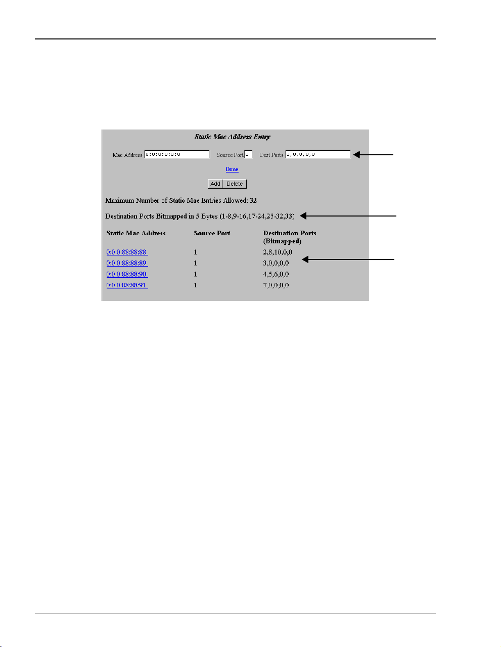
Defining or Modifying Static MAC Entries
You can enter up to 32 static MAC addresses that the modem recognizes in the MAC address
tables. The modem will also learn up to 1024 MAC addresses.
1 Enter Static MAC addresses.
Enter the MAC Address for a device on the LAN. The Mac Address field is case
sensitive and does not accept uppercase alpha characters; use only lowercase alpha
characters (for example, 00:aa:00:46:d6:4c).
Enter a number (1 through 33) for the
the source is the modem LAN port. The port number is 2 through 33 when the
source is one of the 32 sessions. For example, if the source port is the second
session set up (or port 2 on the
The source port number is always one number higher than the port number on the
EasySession page.
Enter a number 1 through 33 for the Destination Port. The port number is 1 when the
destination is the modem LAN port. The port number is 2 through 33 when the
destination is one of the 32 sessions. For example, if the destination port is the
second session set up or port 2 on the
3. The destination port number is always one number higher than the port number
on the
EasySession page.
All static MAC address entries are listed in this table after you enter the parameters
and then Add them.
2 Click
in fields
Add to accept this entry.
Source Port. The port number is 1 when
EasySession page), enter the source port as 3.
EasySession page, enter the destination port as
44 Megabit Modem 400F User Manual
Page 53

3 To delete a Static MAC Address Entry as follows:
Chapter 6: Configuring Sessions
a Click the entry in the list shown in field
Mac address field
b Click
Delete to remove the entry.
.
above to select it. The entry displays in the
4 Click Done when you complete all configuration additions and deletions.
Defining Static Route Entries
You can enter up to 32 static routing IP addresses that the modem recognizes in the routing
address tables, in addition to the routing IP addresses that the modem learns.
page 66 for more information on defining static route entries
.)
(See “Routing” on
1 Enter static routes.
Enter the IP Address and net mask destination.
Enter the Gateway IP address to the next hop.
2 Click
3 To delete a
Add to accept this entry.
Static Route Entry:
a Click the entry in the list shown in field
Static Route Entry field and .
b Click
Delete to remove the entry.
above to select it. The entry displays in the
4 Click Done when you complete all configuration additions and deletions.
Megabit Modem 400F User Manual 45
Page 54

Activating and Deactivating Sessions
ACTIVATING AND DEACTIVATING SESSIONS
Use the following procedures to activate sessions as you want to use them. Additionally, you
may want to deactivate some sessions while leaving other sessions active.
The EasySession page provides status for each session. Up means that connection is active. Down
means the connection is not active. Set-Up means the modem is negotiating the link with the
service provider.
Up, Down , and Set-Up are read-only fields that provide status for the session.
If you powerdown the modem with sessions enabled, those same sessions will
be enabled when you again power up the modem.
Activating Sessions
1 On the EasySession main page, select the box next to each session that you want to activate.
Click to
select
sessions
2 Click
46 Megabit Modem 400F User Manual
Enable at the bottom of the EasySession page to activate the selected sessions.
Page 55

Chapter 6: Configuring Sessions
Deactivating Sessions
On the Web browser, click the Reload icon (shown to the right) to refresh the screen.
1 On the
to deselect.
Click to
select
sessions
EasySession main page, select the box next to each session that you want
2 Click
Megabit Modem 400F User Manual 47
Disable at the bottom of the EasySession page to disable the selected sessions.
Page 56

Activating and Deactivating Sessions
48 Megabit Modem 400F User Manual
Page 57

VIEWING STATISTICS
You can view status for the ADSL link (“Viewing ADSL Status”)andforWANandLAN
statistics (“Viewing Network Statistics” on page 52).
VIEWING ADSL STATUS
The Megabit Modem 400F displays the status of the ADSL link. From the Main Menu, select
ADSL to display the ADSL Menu and ADSL Statistics page (see page 50). Reset on the ADSL Menu
will bring down the ADSL loop between the modem and the service provider.
7
Megabit Modem 400F User Manual 49
Page 58

Viewing ADSL Status
Description of the ADSL Statistics fields are on page 51.
.
Click Main to return
to Main Menu
50 Megabit Modem 400F User Manual
Page 59

Chapter 7: Viewing Statistics
ResetontheADSLMenuwillbringdowntheADSLloopbetweenthemodem
and the service provider.
View the following ADSL statistics:
System time and date and total hours link is up.
ADSL link is synchronized between the modem and the service provider or the link
has no connection.
Any alarm conditions such as Loss of Sync (LOS), Loss of Frame (LOF), Loss of
Margin (LOM), or Loss of Cell Delineation (LCD).
The SNR marginat which the modemis currently operating (dependent onparameters
selected by the service provider).
Minimum SNR margin allowed before the MAR LED on the modem front panel
illuminates.
Total number of errored seconds that the ADSL link has in a 24-hour span.
Total amount of time that the lines were not available for transmission since power on
occurred or the modem statistics were last cleared (total unavailable seconds).
Line attenuation in decibels.
The upstream and downstream data rates at which your modem is connected.
Select Clear to reset all statistics.
Megabit Modem 400F User Manual 51
Page 60

Viewing Network Statistics
VIEWING NETWORK STATISTICS
The Megabit Modem 400F displays status for the LAN and WAN links. From the Main Menu,
Statistics to display the Statistics Menu.
select
LAN Statistics
The Megabit Modem 400F displays status for the LAN. Click LAN Statistics from the
Statistics Menu
.
Click Main
to return to
Main Menu
[
52 Megabit Modem 400F User Manual
Page 61

Chapter 7: Viewing Statistics
View the following LAN information:
System time and date and total hours link is up.
IP and Ethernet addresses for the modem LAN port.
Total number of IP packets processed.
Number of errored packets detected at this port and the number of packets forwarded.
Number of packets reassembled at this port and the number of transmissions where a
route was not found in router table.
Total number packets received and transmitted.
Total number of packets dropped and the number of collisions of devices on segment.
Selecting Clear resets all statistics.
Megabit Modem 400F User Manual 53
Page 62

Viewing Network Statistics
WAN Statistics
The Megabit Modem 400F displays status for the WAN. Click WAN Statistics from the Statistics
Menu
. The values in the statistics fields are a total for all VCs configured.
Click Main
to return to
Main Menu
View the following WAN information:
System time and date and total hours the link is up.
Statistics for the ATM layer including how many Protocol Data Units (PDUs)
were transmitted and received on the session and how many PDUs were corrupted
(Bad PDUs).
Select Clear to reset statistics.
54 Megabit Modem 400F User Manual
Page 63

MAINTENANCE AND
TROUBLESHOOTING
MAINTENANCE
You can update software by specifying a device on your LAN where you will place new
software for the update (see “Defining TFTP Parameters” on page 30). Then, use the procedure
“Updating Software” on page 55 to download new software from the TFTP device to the
Megabit Modem 400F.
Through the RS-232 MGMT port on the Megabit Modem 400F, you can change the modem
LAN port IP address and network mask, the default gateway IP address, and the IP address for
the device on the LAN that can administer the modem (see page 57).
Updating Software
You may want to download software upgrades to your system. Use the Web page shown on
page 56 to initiate the upgrade. You download the new software from a TFTP server. You set
up the IP address for the TFTP server and a directory path to the software when you configure
system parameters in Chapter 5, “Defining SNMP Parameters” on page 31 or by clicking on
TFTP in the Upgrade Software menu and entering TFTP server parameters.
To update the Megabit Modem 400F software, ensure that the .bin file is available to download
from a TFTP server. The .bin file contains the bin (binary) image files for software updates and
htm (HTML) files for web page updates.
8
Megabit Modem 400F User Manual 55
Page 64

Maintenance
Before initiating a software upgrade, ensure that the file is in the directory you
specified on the TFTP server when you configured system parameters.
1 Click System on the Main Menu to access the System Menu.
2 Click Upgrade Software on the System Menu then click Proceed. The modem software
upgrade for binary and HTML files automatically begins.
Click Main
to return to
Main Menu
3 Click
TFPTP to see theTFTP server parameters. The TFTPserver IP address, net mask, path
tp TFTP server, and download file name is displayed. These parameters can be changed if
necessary.
56 Megabit Modem 400F User Manual
Page 65

Chapter 8: Maintenance and Troubleshooting
Using the RS-232 Management Port
Use the RS-232 management port only when you must manually change the IP address and
subnet mask. Also, use the port if you do not remember the administrative IP address you
enteredonyourmodem.
1 Connect the modem to a PC as shown below.
Megabit Modem 400F
Network device
RS-232 MGMT port
MDI
M
DI-X
10BASE-T
RS232
M
GMT
D
S
L
P
O
W
E
R
2 Configure these communication settings (if using terminal emulation, select ANSI):
• 9600 baud
• no parity
• 8databits
• stop bit
• flow control off
Megabit Modem 400F User Manual 57
Page 66

Maintenance
3 Display the following screen:
Pairgain Megabit Modem 400F Setup Menu
===========================================
BSP version: 3.0.0(1)
SW version: 3.1.2
IP address: 192.168.0.1
IP network mask: 255.255.255.0
Default gateway IP address: 0.0.0.0
Admin IP address: 0.0.0.0
===========================================
(1)Enter IP address
(2)Enter IP network mask
(3)Enter default gateway IP address
(4)Enter IP Admin address
(5)Reset modem
4 Enter any of these parameters at the prompt:
a Type then enter the LAN IP address for the modem (LAN port which is the
1
10/100BASE port).
b Type then enter the LAN IP network mask for the modem.
c Type then enter the Default gateway IP address.
d Type then enter theIP address for a device on the LAN that willmanage the modem.
5 Type to reset the modem after you change the LAN IP address and the LAN IP
2
3
4
5
network mask.
58 Megabit Modem 400F User Manual
Page 67

Chapter 8: Maintenance and Troubleshooting
SETTING UPTHEPC TO REQUEST AN IP ADDRESS
The modem, as a Dynamic Host Configuration Protocol (DHCP) server, provides an IP address
dynamically to devices on the LAN. When you choose to use DHCP for the modem to serve
IP addresses to the devices on your LAN, ensure that the TCP/IP properties are set to
automatically obtain the IP address from the modem.
®
The following is an example of how to set up the PC using Microsoft
use an application other than Windows 95, refer to the appropriate operating system user
documentation.
Windows®95. If you
1 Open the
Control Panel window and double-click on the Network icon
shown at right.
2 In the Network dialog (shown below), double-click TCP/IP under the
Configuration tab (or highlight TCP/IP then click Properties).
3 On the
IP Address tab, select Obtain an IP address automatically, then click OK.
4 Restart the PC.
Megabit Modem 400F User Manual 59
Page 68

Troubleshooting
TROUBLESHOOTING
If this occurs: Try this:
PC or hub not
communicating
with the modem
SYNC ADSL LED Contact the service provider when the LED remains off indicating that the modem is not
MARGIN ADSL
LED lights green
LAN TX and RX
LEDs are not on
ADSL TX and RX
LEDs are not on
• Check the LINK LED. If it is off, check the cabling to the 10/100BASE port and to the hub
or the NIC card in the PC to ensure it is secure.
• Check the position of the MDI/MDI-X switch. Set the switch to MDI when connecting to
a PC. Set the switch to MDI-X when connecting to a hub or router.
• Check that you are using a Web browser (Netscape or Internet Explorer) version 4.0
or newer.
• Check that you have a TCP/IP protocol stack installed on your PC.
• If this is the initial installation, check that you set the IP address on your PC to obtain an
IP address automatically. Make sure you have configured the LAN IP address of the
modem to an address that is on the correct subnet. See “Setting Up the PC To Configure
the Modem” on page 18.
• You configured the LAN IP address of the modem to an address that is not on the
same subnet.
• Check the NIC card installation for correct IRQ, drivers, and adapter setup. See
appropriate documentation for the NIC card.
If none of the above corrects your problem, contact your service provider.
detecting a transceiver at the far end. Flashing green indicates that the modem is attempting
to bring up the link. Solid green indicates that the loop is up.
The modem synchronizes at a minimum transmission rate of 64Kbps. The modem rate
adapts in increments of 32Kbps.
Contact the service provider when the LED is off indicating that the margin is below that
specified by the service provider.
Check that the LINK LED is on. If it is on, you are simply not transmitting or receiving data
on the LAN 10/100BASE-T port. If, however, the LINK LED is not on, check the section “PC
or hub not communicating with the modem” in this table.
Check that the SYNC LED is on. If it is on, you are simply not transmitting or receiving data
on the WAN ADSL port. If, however, the SYNC LED is not on, contact your service provider.
60 Megabit Modem 400F User Manual
Page 69

TECHNICAL REFERENCE
This chapter provides technical information about how your modem transmits data between
users on your LAN and a service provider over the WAN.
ADSL
Asymmetric Digital Subscriber Line (ADSL) is the technology used to transmit data between
the modem and service provider at the physical layer. It provides data at asymmetric rates so
that downstream traffic from a service provider to you is faster than upstream traffic from you
to the service provider. The downstream transmission rate is up to 7.552 Mbps, while the
upstream rate is up to 928 kbps. Included in the ADSL bandwidth is analog POTS.
Discrete Multitone (DMT) is the line coding used for ADSL. Basically, it divides the
bandwidth into subchannels. Some of the subchannels are reserved for analog POTS. The
other subchannels are allocated to upstream and downstream traffic. Within the upstream
and downstream subchannels, some subchannels are used for management and
performance functions.
DMT ADSL provides rate-adaptive transmission that allows the service provider to deliver you
the best transmission rate determined by distance and line conditions.
9
ATM
Asynchronous Transfer Mode (ATM) is a technology that can simultaneously transmit voice,
data, and video over ADSL. ATM uses fixed-size cells that transmit over a preestablished
connection called a Permanent Virtual Circuit (PVC). Quality of Service provides UBR.
ATM cellsare 53 bytes thatcomprise a 5-byte header and 48-byte payload.The header includes
the Virtual PathIdentifier (VPI) and Virtual Channel Identifier(VCI) that you enteredwhen you
configured each session in Chapter 4. TheVPI and VCI provide the virtual connection between
the modem and the service provider. The VPI identifies the Virtual Path (VP) that transports
Megabit Modem 400F User Manual 61
Page 70

ATM
ATM cells in a Virtual Channel (VC). The Megabit Modem 400F has 32 VCs in the VP, which
provides the 32 sessions.
Mapping an ATM Session
Your service provider will give you a VCI and VPI address for each session. The VCI address
for each session (each session is a VC) can be a number from 32 up to a maximum of 255, with
the first 32 numbers (0 through 31) reserved. The VCI value for each VC must be unique for
each of the 32 sessions. The addresses range from 0 to 253 for VCI and 0 to 15 for VPI.
62 Megabit Modem 400F User Manual
Page 71

Chapter 9: Technical Reference
RATE ADAPTIVE TRANSMISSION
The following definitions are useful for understanding the operation of the Megabit Modem:
• Bit Error Rate (BER) is the ratio of receivedbits that arein error relative to the total number
-7
of bits received, measured over time. For example, 10
7
error occurs per 10
bits received.
BER means that on average one
• Signal to Noise Ratio (SNR) is the ratio (typically expressed in dB) of the received signal
power to the received noise power. It is a measure of the quality of the transmission.
• Margin (SNR margin) is the amount of degradation in SNR that the system can tolerate
-7
under the current conditions and still achieve 10
means that the SNR can degrade by 6 dB and still provide a performance of 10
BER. A margin of 6 dB, for example,
-7
Megabit Modem 400F have a margin configuration option that defaults to 3 dB, but can be
set anywhere between 0 to 15 dB.
• Reach is the longest loop length that the system can support with a given margin.
Rate Adaptation
With ADC's rate adaptive technology, the Megabit Modem 400F can automatically startup or
adjust to the fastest speed possible, given the transmission distance and line conditions. Or, you
can set the modem to a specific rate.
Reach, Data Rate, SNR Margin, and Noise Environment
The maximum transmission rate of the Megabit Modem 400F is determined by distance, SNR
margin, and the condition of the line (wire gauge, condition noise environment). The figure on
page 73 shows the relationship between reach and data rate for a given set of conditions. The
plots can be used to determine the achievable reach at a given data rate, or they may be used to
determine the achievable data rates at a given distance. In all cases except the no noise case, a
margin of 4 dB was allocated above the SNR that provides a 10
-7
BER.
BER. The
Megabit Modem 400F User Manual 63
Page 72

Bridging and Routing
BRIDGING AND ROUTING
Bridging
You can configure the Megabit Modem 400F as a bridge to forward Ethernet data based on
MAC addresses.
MAC Layer Bridging
A bridge moves information across an internetwork from a source to a destination at the link
layer (of an OSI reference model). The information is sent to a physical address known as a
Media Access Control (MAC) address. The Megabit Modem 400F provides transparent
Ethernet MAC-layer bridging.
The bridge learns up to 1024 addresses. Additionally, when you configure the modem, you can
add 32 static addresses through the static MAC address configuration page.
Spanning Tree Protocol
The Megabit Modem 400F supports 802.1d Spanning Tree protocol which eliminates loops in
a LAN topology by partitioning out redundant links between LAN segments. This ensures that
there is only one path, or link, between any two nodes on the network. If this link goes down,
Spanning Tree re-enables partitioned links to create a new loop-free topology if possible.
An example of the active topology is shown on page 65. In the example, the spanning tree
algorithm partitions out the bridge from LAN A to LAN B, and creates the link from ENET2
to Bridge 5.
64 Megabit Modem 400F User Manual
Page 73

Example LAN Physical Network
This physical configuration is valid only when used with
Spanning Tree to eliminate loops.
LAN
Bridge 3Bridge 2Bridge 1
ENET 1
LAN
Bridge 4
E
N
E
T
2
Bridge 5
ENET 3
Chapter 9: Technical Reference
Loop-free Topology
Using SpanningTree Protocol
LAN A
Bridge 3Bridge 2Bridge 1
ENET 1
LA BN
Bridge 4
Megabit Modem 400F User Manual 65
E
N
E
T
2
Bridge 5
ENET 3
Page 74

Bridging and Routing
Routing
You can configure the Megabit Modem 400F router to route Ethernet-encapsulated
IP datagrams based on IP addresses. Use Routing Information Protocol (RIP) to automatically
identify the route from the session on the Megabit Modem 400F to the destination. You can
specify the direction and version of RIP that allows other routers to update their routing tables
automatically (for example, information on how many hops between destinations). The version
of RIP you select for the session must match the version supported by the service provider.
Versions RIP1 and RIP-1 compatible are used for broadcast. Version RIP 2 is used
for multicast.
The router also learns addresses. In addition to the addresses it learns, you can add 32 static
route entries on the LAN Brouter configuration page. Through the static IP routing feature, you
can configure the Megabit Modem 400F as an IP router with statically programmed route
entries. You canenable this function to providebroadcast filtering and to preventeavesdropping
by specifying multiple destination gateways. When static IP routing is enabled, you can access
only specific remote IP subnets or hosts.
Since IP routers make forward or filter decisions based on the network-layer IP address instead
of the MAC hardware address, MAC-level broadcast frames are prevented from reaching
unwanted destinations in the network.
When setting parameters for an external router, configure a Static Route entry in any of the
external routers that may have been specified as a Default Router or as a Gateway. This
implementation prevents other parties from discovering routes through eavesdropping. The
format of this entry varies among the various router vendors, but is typically in the form of
"Destination," "Mask," and "Gateway," where the "Destination" is the remote IP Subnet or host
address, and "Gateway" is the IP address of the modem on the same subnet as the external
router.
Encapsulation for RFC 1483 Bridging/Routing
Most users select LLC, which allows you to run multiple protocols over the VC. An
encapsulation header identifies the types of protocol being carried in the transmission (for
example, IP). VC-MUX allows only one protocol to run over the VC. The type of protocol must
be negotiated between the modem and the service provider prior to the transmission. Because
there is only one protocol allowed, the header is not required. This configuration is normally
setup by the service provider.
66 Megabit Modem 400F User Manual
Page 75

Chapter 9: Technical Reference
MANAGEMENT PROTOCOLS
SNMP is used to configure system and bridge parameters, to monitor statistics, and to perform
advanced management tasks.
SNMP
This management protocol specifies how to send information between a network management
system (NMS) and managed devices on a network. Managed devices run a program called an
agent. The agentinterprets SNMP requests and responds tothem. The NMS communicateswith
the agents in the managed devices to:
• set configuration
• get configuration
• get status
A Management Information Base (MIB) defines the configuration and status parameters.
The Internet Engineering Task Force (IETF) specifies standard MIBs for certain types of
devices, ensuring any NMS can manage them. Additionally, vendors can issue proprietary
MIBs for their devices to fit specific needs.
Megabit Modem 400F User Manual 67
Page 76

DNS Resolution
MIBs and Traps
RFC 1213: "Management Information Base for Network Management of TCP/IP-Based Internet: MIB-II"
RFC 1493: "Definition of Managed Objects for Bridges"
RFC 1215: "A Convention for Defining Traps for Use with the SNMP"
ADSL MIB
PairGain Agent MIB
PairGain Tiger MIB
DNS RESOLUTION
If you want Domain Name System (DNS) resolution, you need to specify the IP address for a
device to be the DNS resolver. You can also specify another IP address to designate a second
device for a secondary DNS resolver. The DNS device maps human-readable addresses to IP
addresses. A human-readable address is one such as maggie.copro.company.com that
contains a host name and domain. The DNS resolver maps that name to the IP address that is a
numeric (four octet) value such as 192.168.30.25 (see page 43 for the example on how to
configure a DNS address).
TFTP SERVER
Trivial File Transfer Protocol (TFTP) is the TCP/IP standard for file transfer. It provides
the service with minimal capability and minimal overhead. TFTP uses UDP for
connectionless delivery.
68 Megabit Modem 400F User Manual
Page 77

SPECIFICATIONS AND DATA
WAN INTERFACE SPECIFICATIONS
ADSL (Asymmetric Digital Subscriber Line)
Maximum transmission rate:
Downstream
Upstream
Minimum transmission rate to sync 64 kbps
Rate-adaptive data rate resolution 32 kbps increments
Signal Format DMT (Discrete Multitone) line code
Connector RJ-11
ATM (Asynchronous Transfer Mode)
7.552 Mbps
928 kbps
A
ATM Adaptation Layer AAL5 (ITU I.363.5) - Supports encapsulation and
ATM Layer Attaches or strips the 5-byte header to the 48-byte SAR-PDU.
Cell Format Format complies with ITU I.361 ATM cell format. Cell delineation
Virtual Circuit type Permanent Virtual Circuit (PVC) per ATM forum UNI version 3.1
Maximum Virtual Circuits 32 virtual circuits that can simultaneously connect to service
Megabit Modem 400F User Manual 69
de-encapsulation of AAL5 Protocol Data Units (PDUs) for
convergence. Segmentation and Reassembly (SAR) layer
segments and reassembles AAL5 PDUs into ATM cells that are
48-byte SAR-PDUs.
Performance is a maximum line rate of 17,812 cells per second
downstream and 2,189 cells per second upstream.
complies with ITU I.432 Cell Delineation and HEC. Cells are fixed
length (53 bytes), including 5 bytes of header and 48 bytes of
payload. Included in the header are the VPI and VCI number.
providers for sessions encapsulated either as RFC 1483
Bridging/Routing
Page 78

Encapsulation
ENCAPSULATION
When you activate RFC 1483 system mode, you can select WAN encapsulation as VC-MUX
for some sessions and LLC for other sessions.
Routing
Routing Protocol Supports RFC 1724 Routing Information Protocol (RIP and RIP Version 2).
Encapsulation Supports Logical Link Control (LLC) or VC-based multiplexing (RFC 1483).
Static Routes Supports up to 32 static routes
Address Resolution Supports Address Resolution Protocol (ARP) over the LAN port (RFC 826)
Bridging
Bridging and Address
Learning
Encapsulation Supports Logical Link Control (LLC) or VC-based multiplexing (RFC 1483).
Spanning Tree Provides Spanning Tree support per IEEE 802.1d.
Implements a transparent learning bridge with a bridging table of 1024 entries.
70 Megabit Modem 400F User Manual
Page 79

LAN INTERFACE
Appendix A: Specifications and Data
Connector RJ-45 Ethernet with auto-detecting10/100BASE-T (IEEE 802.3I for 10BASE-T and
IEEE 802.3u for 100BASE-T)
PHYSICAL SPECIFICATIONS
Height 1.2 inches (3.1 cm)
Width 6.9 inches (17.5 cm)
Depth 9.2 inches (23.4 cm)
Weight 2.2 pounds (1.0 kg)
POWER SUPPLY
Voltage 100 to 240 Vac
Frequency 50 to 60 Hz
Current 0.3 Amps
ENVIRONMENTAL
Temperature 32 to 122 °F (0 to 50°C)
Relative Humidity up to 95% non-condensing
Altitude between -200 and 13,000 feet (-61 to 3.962 meters)
Megabit Modem 400F User Manual 71
Page 80

Compliance
COMPLIANCE
Emissions and Immunity
Compliance
Operations and Safety
Compliances
• FCC Part 15, Subpart B, Class B
• CENELEC/ETSI (IEC 555 and 801)
• CE (EN 55022 and EN 50082-1)
• cUL (UL-1950)
• CE (EN 300 386-01)
• ICE 950
RFCS
• RFC 1483 Multiprotocol Encapsulation over ATM (Bridging/Routing)
• RFC 1994 for PAP/CHAP Authentication
• RFC 1631 IP Network Address Translator (for NAPT)
• RFC 1350 for TFTP client
• RFC 2131 and RFC 2132 for DHCP server and relay protocols (supported only in RFC 1483
Bridging mode) and extensions, respectively
• RFC 1493 Definitions of managed objects for bridges
• RFC 1695 Definitions of managed objects for ATM Management Version 8.0 using SMIv2
• RFC 1724 RIP Version 2 MIB Extensions
• RFC 2132 DHCP Options and BOOTP Vendor Extensions
• RFC 2662 Definitions of managed objects for ADSL lines (Also DSL Forum TR-006)
MIBS
• RFC 1213 Management Information Base for Network Management of TCP/IP-based internets:
MIB-II
• RFC 1215 Conventions for defining traps for use with SNMP
• RFC 1493 Definitions of managed objects for bridges
• RFC 1695 Definitions of managed objects for ATM Management Version 8.0 using SMIv2
• RFC 1724 RIP Version 2 MIB Extensions
• RFC 2662 Definitions of managed objects for ADSL lines (Also DSL Forum TR-006)
• Pairgain Tiger MIB
• Pairgain Agent MIB
72 Megabit Modem 400F User Manual
Page 81

RATE VS.REACH
Payload Rate vs Reach on 24 AWG (0.4 mm) with 4dB Margin in Low Noise Environment
10.000
1.000
Rate in Mbps
0.100
0.010
0.0
1.0
2.0
3.0
Payload Rate vs Reach on 26 AWG (0.5 mm) with 4dB Margin in Low Noise Environment
10.000
Appendix A: Specifications and Data
4.0
5.0
6.0
7.0
8.0
9.0
10.0
11. 0
12.0
13.0
14.0
15.0
16.0
17.0
18.0
19.0
20.0
21.0
22.0
23.0
24.0
25.0
26.0
Reach in Kilofeet
Downstream
Upstream
27.0
1.000
Rate in Mbps
0.100
0.010
0.0
1.0
2.0
3.0
4.0
5.0
6.0
7.0
8.0
9.0
10.0
11. 0
12.0
13.0
14.0
15.0
16.0
17.0
18.0
19.0
20.0
21.0
22.0
23.0
24.0
25.0
26.0
Reach in Kilofeet
Downstream
Upstream
27.0
Megabit Modem 400F User Manual 73
Page 82

Hardware
HARDWARE
The following provides additional information about Megabit Modem 400F such as the
installation kit and modem connectors pinouts.
Installation Kit
The following items are included in the installation kit and are used to install the Megabit
Modem 400F as shown in Chapter 3 on page 11.
Part Description Function
Rubber feet Four black rubber feet Attaches to the base of the modem.
Grey cable Silver-satin phone cord with 4-pin modular
Black cable CAT 5, cable with 8-pin modular plugs
Power cable Power supply with optional power cord (this
Screws Two 6x
Grey cable
and adapter
plugs (straight-through)
(straight-through)
item is ordered dependent on the type of
power supply and cord required for your
location)
1
/2-inch sheet metal screws Installs into a wall for wall-mounting modems.
Flat cable with RJ-45 connectors and a DB-9
to RJ-45 adapter.
Connects the modem ADSL connector to the
wall phone jack for access to the Internet.
Connects the modem 10/100BASE-T connector
to the LAN through a hub or to a PC NIC.
Connects the modem POWER connector to the
local power source.
Connects the RS-232 MGMT port to an ASCII
terminal or a PC running terminal emulation
software. Adapter assembly connects to a DB-9
connector on the PC. Then, one RJ-45 connector
installs in the adapter and the other connector
into the console port on the modem.
74 Megabit Modem 400F User Manual
Page 83

Appendix A: Specifications and Data
Connector Pinouts
You may choose to make your own cables for the ADSL RJ-11 connector and the
10/100BASE-T Ethernet connector on the rear of the modem. The following sections provide
the pinout information you need.
ADSL Port
The following table shows the signal on each pin for the ADSL port. The connector for this
interface is an RJ-11. See page 14 for the location of this port.
Pin Signal
1 Not used
2 No connection
3Ring
4Tip
5 No connection
6 Not used
10/100BASE-T Port
The following table shows the signal on each pin when the switch is in either the MDI or
the MDI-X position for the 10/100BASE-T port. The connector for this interface is an RJ-45.
See page 14 for the location of this port.
MDI MDI-X Signal Description
13TX+Transmit Data (+)
26TX-Transmit Data (-)
3 1 RD+ Receive Data (+)
4 4 Not used Not used
5 5 Not used Not used
6 2 RD- Receive Data (-)
7 7 Not used Not used
8 8 Not used Not used
Megabit Modem 400F User Manual 75
Page 84

Hardware
76 Megabit Modem 400F User Manual
Page 85

TECHNICAL ASSISTANCE
AND
This chapter describes how to contact ADC for technical support and warranty service.
WARRANTY
TECHNICAL SUPPORT
Technical support is available 24 hours a day, 7 days a week by contacting the ADC Wireline
Systems Division Customer Service Engineering Group at one of the following numbers:
• Telephone: 800.638.0031
714.730.3222
• Fax: 714.832.9924
• Email wsd_support@adc.com
A Customer Service Engineer answers technical assistance calls Monday through Friday
between 7:30 AM and 5:30PM, Pacific Time, excluding holidays. At all other times, an on-duty
Customer Service Engineer returns technical assistance calls within 30 minutes.
WORLD-WIDE WEB
B
Avidia product information can be found at http://www. pairgain.com usinganywebbrowser.
To download product manuals from the Customer Site portion of the web page, you need to
provide a customer password. If you do not have a password, contact your sales representative.
Megabit Modem 400F User Manual 77
Page 86

Limited Warranty
LIMITED WARRANTY
ADC DSL Systems, Incorporated (“ADC”) warrants that, for a period of twelve (12) months
from the date of shipment, the hardware portion of its products will be free of material defects
and faulty workmanship under normal use. ADC's obligation, under this warranty, is limited to
replacing or repairing, at ADC'soption, any such hardware product whichis returned during the
12-month warranty period per ADC's instructions and which product is confirmed by ADC not
to comply with the foregoing warranty.
ADC warrants that, for a period of 90 days from the date of purchase, the software furnished
with itsproducts will operate substantially inaccordance with the ADC published specifications
and documentation for such software. ADC’s entire liability for software that does not comply
with the foregoing warranty and is reported to ADC during the 90-day warranty period is, at
ADC’s option, either (a) return of the price paid or (b) repair or replace of the software. ADC
also warrants that, for a period of thirty (30) days from the date of purchase, the media on which
software is stored will be free from material defects under normal use. ADC will replace
defective media at no charge if it is returned to ADC during the 30-day warranty period along
with proof of the date of shipment.
The transportation charges for shipment of returned products to ADC will be prepaid by the
Buyer. ADC will pay transportation charges for shipment of replacement products to Buyer,
unless no trouble is found (NTF), in which case the Buyer will pay transportation charges.
ADC may use reconditioned parts for such repair or replacement. This warranty does not apply
to any product which has been repaired, worked upon, or altered by persons not authorized by
ADC or in ADC's sole judgment has been subjected to misuse, accident, fire or other casualty,
or operation beyond its design range.
Repaired products have a 90-day warranty, or until the end of the original warranty
period—whichever period is greater.
ADC DISCLAIMS ALL OTHER WARRANTIES, EITHER EXPRESS OR IMPLIED,
INCLUDING BUT NOT LIMITED TO IMPLIED WARRANTIES OF
MERCHANTABILITY AND FITNESS FOR APARTICULAR PURPOSE, WITH RESPECT
TO ITS PRODUCTS AND ANY ACCOMPANYING WRITTEN MATERIALS. FURTHER,
ADC DOES NOT WARRANT THAT SOFTWARE WILL BE FREE FROM BUGS OR
THAT ITS USE WILL BE UNINTERRUPTED OR REGARDING THE USE, OR THE
RESULTS OF THE USE, OF THE SOFTWARE IN TERMS OF CORRECTNESS,
ACCURACY, RELIABILITY OR OTHERWISE.
78 Megabit Modem 400F User Manual
Page 87

Appendix B: Technical Assistance and Warranty
ADVANCE REPLACEMENT
Any productdetermined byADC not tocomply withthe applicable warrantywithin 30calendar
days fromthe date of shipment to the Buyer, or as otherwise authorized, are eligible for advance
replacement free of charge. A replacement productwill beshipped to theBuyer within 24 hours
of ADC's receipt of notification from the Buyer.
If products returned to ADC for advance replacement are not received by ADC within 30
calendar days of shipment of the replacement product or if no trouble is found (NTF) as
determined by ADC, the Buyer will be responsible for payment of the cost of the replacement
product.
BILLING
ADC’s repair of products returned for repair, replacement, or credit, whether in warranty or out
of warranty, which is found to be damaged due to customer negligence or which has had parts
removed will be billed on a time and material basis.
In the event that the returned equipment is not covered by warranty, ADC will contact the
customer with the estimated repair or replacement charges and obtain customer disposition of
the product if a purchase order has not been provided.
Equipment returned forrepair or replacement is subjectto a $70 per unit NTF(no trouble found)
charge in the event that diagnostic evaluation reveals no evidence of functional failure or
physical defects.
Megabit Modem 400F User Manual 79
Page 88

Returning a Product
RETURNING A PRODUCT
To return equipment to ADC Wireline Systems Division:
1 Locate the number of the purchase order under which the equipment was purchased. You
will need to provide this number to ADC Wireline Systems Division Customer Service to
obtain a return authorization.
2 Call or write ADC Wireline Systems Division Customer Service to ask for a Return
Material Authorization (RMA) number and any additional instructions. Use the telephone
number, fax number, or email address listed below:
• Telephone: 800.370.9670
• Fax: 714.832.9923
• Email Address: rma@adc.com
3 Include the following information, in writing, along with the equipment you are returning:
• Company name, address, telephone number, and the name of a person Customer
Service can contact regarding this equipment.
• The purchase order number provided to Customer Servicewhen the RMA number was
requested.
• A description of the equipment, as well as the number of units that you are returning.
Be sure to include the model and part number of each unit.
• The shipping address to whichCustomer Service should returnthe repaired equipment.
• The reason for the return:
– The equipment needs an ECO/ECN upgrade.
– The equipment is defective.
If the equipment is defective, please tell us what you observed just before the
equipment malfunctioned. Be as detailed in your description as possible.
– If there is another reason for returning the equipment, please let us know so we
can determine how best to help you.
4 Pack the equipment in a shipping carton.
80 Megabit Modem 400F User Manual
Page 89

Appendix B: Technical Assistance and Warranty
5 Write the ADC Wireline Systems Division address and the Return Material Authorization
Number you received from Customer Service clearlyon the outside ofthe carton andreturn
to:
ADC Wireline Systems Division
14352 Franklin Ave.
Tustin, CA 92780-7013
Attention: RMA (Number)
All shipments are to be returned prepaid. ADC will not accept any collect
shipments.
Megabit Modem 400F User Manual 81
Page 90

Returning a Product
82 Megabit Modem 400F User Manual
Page 91

CONFIGURATION WORKSHEETS
This chapter provides worksheets where you can record your system settings and system
sessions configuration information prior to executing the procedures in Chapter 4 through
Chapter 7.
The information that you need to configure the modem is listed below. Contact your service
provider for this information. Use the worksheets in this appendix to record your configuration
information. When you begin configuration of the modem in Chapter 4, the procedures refer
you to the proper table so you can use the information you have recorded.
CONFIGURATION INFORMATION
1 System mode Bridge/Router RFC 1483.
2 Bridge/Router:
• Configure as a Bridge only, as a Router only, or as a Bridge and Router.
• If Bridge or Router, choose LLC or VC-MUX encapsulation.
• If Router, choose version of and direction for RIP (RIP1, RIP2, or RIP1 compatible).
C
• If Bridge, select whether or not to enable Spanning Tree.
3 Session address for Ports 1 through 32 (WAN configuration):
• ATM VPI and ATM VCI (specified for each session)
• when using fixed IP addresses, IP address specified for each session by the
service provider
Megabit Modem 400F User Manual 83
Page 92

Configuration Information
System Mode Worksheet
Contact Service Provider: Configuration Type
Enter system mode:
• Bridging/Routing
If Bridging/Routing, select one:
• Bridge and Router?
• Bridge only?
• Router only?
If Bridging and/or Routing, choose
Encapsulation method?
• LLC
• VC-MUX
When Routing with RIP, select:
• RIP direction
• Version of RIP
When Bridging, Enable Spanning Tree?
(YES OR NO)
__________________________
__________________________
__________________________
__________________________
__________________________
__________________________
84 Megabit Modem 400F User Manual
Page 93

WAN Configuration Worksheet
From Service Provider Configuration Information
Appendix C: Configuration Worksheets
ATM Configuration
(VPI/VCI for each session)
VPI
1 __________________________
2 __________________________
3 __________________________
4 __________________________
5 __________________________
6 __________________________
7 __________________________
8 __________________________
9 __________________________
10 __________________________
11 __________________________
VCI
1 __________________________
2 __________________________
3 __________________________
4 __________________________
5 __________________________
6 __________________________
7 __________________________
8 __________________________
9 __________________________
10 __________________________
11 __________________________
12 __________________________
13 __________________________
14 __________________________
15 __________________________
16 __________________________
Megabit Modem 400F User Manual 85
12 __________________________
13 __________________________
14 __________________________
15 __________________________
16 __________________________
Page 94

Configuration Information
WAN Configuration Worksheet - continued
From Service Provider Configuration Information
ATM Configuration
(VPI/VCI for each session)
VPI
17 _________________________
18 _________________________
19 _________________________
20 _________________________
21 _________________________
22 _________________________
23 _________________________
24 _________________________
25 _________________________
26 _________________________
27 _________________________
VCI
17 _________________________
18 _________________________
19 _________________________
20 _________________________
21 _________________________
22 _________________________
23 _________________________
24 _________________________
25 _________________________
26 _________________________
27 _________________________
28 _________________________
29 _________________________
30 _________________________
31 _________________________
32 _________________________
86 Megabit Modem 400F User Manual
28 _________________________
29 _________________________
30 _________________________
31 _________________________
32 _________________________
Page 95

Login Name / Login Password Worksheet
From Service Provider Login Information
Appendix C: Configuration Worksheets
Login Name and Login
Password
(for each session)
Login Name
1 ____________________________
2 ____________________________
3 ____________________________
4 ____________________________
5 ____________________________
6 ____________________________
7 ____________________________
8 ____________________________
9 ____________________________
10 ____________________________
Login Password
1 ____________________________
2 ____________________________
3 ____________________________
4 ____________________________
5 ____________________________
6 ____________________________
7 ____________________________
8 ____________________________
9 ____________________________
10 ____________________________
11 ____________________________
12 ____________________________
13 ____________________________
14 ____________________________
15 ____________________________
16 ____________________________
Megabit Modem 400F User Manual 87
11 ____________________________
12 ____________________________
13 ____________________________
14 ____________________________
15 ____________________________
16 ____________________________
Page 96

Configuration Information
Login Name / Login Password Worksheet - continued
From Service Provider Login Information
Login Name and Login
Password
(for each session)
Login Name
17 ____________________________
18 ____________________________
19 ____________________________
20 ____________________________
21 ____________________________
22 ____________________________
23 ____________________________
24 ____________________________
25 ____________________________
26 ____________________________
Login Password
17 ____________________________
18 ____________________________
19 ____________________________
20 ____________________________
21 ____________________________
22 ____________________________
23 ____________________________
24 ____________________________
25 ____________________________
26 ____________________________
27 ____________________________
28 ____________________________
29 ____________________________
30 ____________________________
31 ____________________________
32 ____________________________
88 Megabit Modem 400F User Manual
27 ____________________________
28 ____________________________
29 ____________________________
30 ____________________________
31 ____________________________
32 ____________________________
Page 97

Appendix C: Configuration Worksheets
Fixed IP Addresses Worksheet
From Service Provider Fixed IP Addresses
Fixed IP Addresses
(for each session)
Fixed IP Address
1___________
2___________
3___________
4___________
5___________
6___________
7___________ . ___________ . ___________ . ___________
8___________
9___________ . ___________ . ___________ . ___________
10___________
. ___________ . ___________ . ___________
. ___________ . ___________ . ___________
. ___________ . ___________ . ___________
. ___________ . ___________ . ___________
. ___________ . ___________ . ___________
. ___________ . ___________ . ___________
. ___________ . ___________ . ___________
. ___________ . ___________ . ___________
11___________
12___________ . ___________ . ___________ . ___________
13___________
14___________
Not applicable if service provider
dynamically assigns IP addresses.
Megabit Modem 400F User Manual 89
15___________ . ___________ . ___________ . ___________
16___________
. ___________ . ___________ . ___________
. ___________ . ___________ . ___________
. ___________ . ___________ . ___________
. ___________ . ___________ . ___________
Page 98

Configuration Information
Fixed IP Addresses Worksheet - continued
Contact Service Provider Fixed IP Addresses
Fixed IP Addresses
(for each session)
Fixed IP Address
17__________
18__________
19__________
20__________
21__________
22__________
23__________ . __________ . __________ . __________
24__________
25__________ . __________ . __________ . __________
26__________
. __________ . __________ . __________
. __________ . __________ . __________
. __________ . __________ . __________
. __________ . __________ . __________
. __________ . __________ . __________
. __________ . __________ . __________
. __________ . __________ . __________
. __________ . __________ . __________
27__________
28__________ . __________ . __________ . __________
29__________
30__________
Not applicable if service provider
dynamically assigns IP addresses.
90 Megabit Modem 400F User Manual
31__________ . __________ . __________ . __________
32__________
. __________ . __________ . __________
. __________ . __________ . __________
. __________ . __________ . __________
. __________ . __________ . __________
Page 99

GLOSSARY
10/100BASE-T The Institute of Electrical and Electronic Engineers (IEEE) 802.3 specification for
Ethernet over thin coaxial cable.
AAL5 ATM Adaptation Layer 5.
D
ADSL Asymmetric Digital Subscriber Line is a technology in which data is transferred from
ATM Asynchronous Transfer Mode is a high bandwidth, low delay, connection-oriented,
attenuation The dissipation of the power of a transmitted signal as it travels over copper wire,
BER Bit Error Rate is a measure of transmission quality. The ratio of error bits to the total
bps bit-per-second is the number of bits transferred during each second of data
CBR Constant Bit Rate is a Service Class for the modem. It provides constant bit rate data
cell A fixed-length packet. Also, the unit of data transmission used in ATM. Each ATM cell
the service provider to the subscriber at up to 7.552 Mbps, and transferred from
subscriber to service provider at up to 928 Kbps. ADSL is the implementation of the
physical layer for transmission of data.
packet-like switching and multiplexing technique that uses 53-byte fixed-size cells to
transmit voice, video and data over a network. ATM layers define how cells are
formatted and provides the transport of the fixed length cells between the modem
and the service provider (or endpoints of the virtual connection).
measured in decibels (dB).
number of bits transmitted.
transmission.
with a timing relationship between the source and the destination. Also, a traffic class
that carries a guaranteed constant bandwidth. Best suited for applications that require
fixed bandwidth, such as uncompressed voice, video and circuit emulation. CBR is a
Quality of Service class defined by the ATM Forum for ATM networks.
contains a fixed-size frame (53 bytes) consisting of a five-byte header and a 48-byte
payload.
Megabit Modem 400F User Manual 91
Page 100

community
string
A text string required for an SNMP trap to be received by a trap receiver(s). Also, a
text string that identifies an SNMP community and is associated with specific access
rights (read-only or read/write).
CRC Cyclic Redundancy Check is a method used to verify the accuracy of data
transmission.
DMT Discrete Multi-Tone is a modulation coding for an ADSL line. DMT is the modulation
technology used for the Megabit Modem 400F ADSL.
downstream
Communications from a service provider to a user.
traffic
encapsulation The inclusion of data in a protocol header prior to transmission, which enables
successful data transmission between different protocol networks.
ES Errored Seconds is the seconds during which errors occur that prevent the payload
from being corrected.
Ethernet A protocol used for LAN traffic, which has a transfer rate of 10 or 100 Mbps.
flash memory Non-volatile memory that can be erased and reprogrammed.
gateway A device (generally a router) that provides translation services to allow
communication between two dissimilar networks.
IP Internet Protocol is a TCP/IP protocol that controls packet transmission.
IP address A 32-bit address used in IP routing. The address consists of four octets separated by
decimals. The octets comprise a network section, a subnet section (optional) and a
host section.
LAN Local Area Network is a physically connected group of devices between which data
transmission occurs at high speeds over relatively short distances.
LLC Logical Link Control is an encapsulation protocol for data that you transmit from the
modem over the WAN in 1483 Bridging/Routing mode.
LOF Loss Of Frame is an error indicating that the receiving equipment has lost a frame.
LOS Loss Of Signal is an error indicating that the receiving equipment has lost the signal.
MAC Media Access Control is a physical address associated with a device such as a NIC.
For modem configuration, the MAC is used to map inbound traffic (from a remote IP
address) to an internal (LAN) IP address. Used with 1483 Bridging/Routing Mode.
margin The noise margin in decibels that the modem must achieve with a BER of 10
-7
or
better to successfully complete initialization.
92 Megabit Modem 400F User Manual
 Loading...