

Page 1

ADCP-92-063 • Issue 1 • May 2005
OptEnet™ 10/100 or 1000 Mb/s
Ethernet Media Converter
Module with SFPs User Manual
Content Page
INTRODUCTION . . . . . . . . . . . . . . . . . . . . . . . . . . . . . . . . . . . . . . . . . . . . . . . . . . . . . . . . . . . . . . . . . . . . . . . . . . . . . 1
Revision History . . . . . . . . . . . . . . . . . . . . . . . . . . . . . . . . . . . . . . . . . . . . . . . . . . . . . . . . . . . . . . . . . . . . . . . . 1
List of Changes. . . . . . . . . . . . . . . . . . . . . . . . . . . . . . . . . . . . . . . . . . . . . . . . . . . . . . . . . . . . . . . . . . . . . . . . . 2
Trademark Information . . . . . . . . . . . . . . . . . . . . . . . . . . . . . . . . . . . . . . . . . . . . . . . . . . . . . . . . . . . . . . . . . . . 2
Related Publications . . . . . . . . . . . . . . . . . . . . . . . . . . . . . . . . . . . . . . . . . . . . . . . . . . . . . . . . . . . . . . . . . . . . . 2
Admonishments . . . . . . . . . . . . . . . . . . . . . . . . . . . . . . . . . . . . . . . . . . . . . . . . . . . . . . . . . . . . . . . . . . . . . . . . 2
General Safety Precautions . . . . . . . . . . . . . . . . . . . . . . . . . . . . . . . . . . . . . . . . . . . . . . . . . . . . . . . . . . . . . . . . 3
FCC Compliance Statement . . . . . . . . . . . . . . . . . . . . . . . . . . . . . . . . . . . . . . . . . . . . . . . . . . . . . . . . . . . . . . . . 3
UL/CSA Certification . . . . . . . . . . . . . . . . . . . . . . . . . . . . . . . . . . . . . . . . . . . . . . . . . . . . . . . . . . . . . . . . . . . . . 3
NEBS Certification. . . . . . . . . . . . . . . . . . . . . . . . . . . . . . . . . . . . . . . . . . . . . . . . . . . . . . . . . . . . . . . . . . . . . . . 3
1 PRODUCT DESCRIPTION . . . . . . . . . . . . . . . . . . . . . . . . . . . . . . . . . . . . . . . . . . . . . . . . . . . . . . . . . . . . . . . . . . 4
1.1 Front Panel. . . . . . . . . . . . . . . . . . . . . . . . . . . . . . . . . . . . . . . . . . . . . . . . . . . . . . . . . . . . . . . . . . . . . . 4
2 UNPACKING AND INSPECTION . . . . . . . . . . . . . . . . . . . . . . . . . . . . . . . . . . . . . . . . . . . . . . . . . . . . . . . . . . . . . . 6
3 INSTALLATION . . . . . . . . . . . . . . . . . . . . . . . . . . . . . . . . . . . . . . . . . . . . . . . . . . . . . . . . . . . . . . . . . . . . . . . . . 6
3.1 1000 Mb/s Module. . . . . . . . . . . . . . . . . . . . . . . . . . . . . . . . . . . . . . . . . . . . . . . . . . . . . . . . . . . . . . . . . 6
3.2 10/100 Mb/s Module . . . . . . . . . . . . . . . . . . . . . . . . . . . . . . . . . . . . . . . . . . . . . . . . . . . . . . . . . . . . . . . 7
4 SPECIFICATIONS. . . . . . . . . . . . . . . . . . . . . . . . . . . . . . . . . . . . . . . . . . . . . . . . . . . . . . . . . . . . . . . . . . . . . . . 10
5 POWER-UP/CHECK OUT PROCEDURE . . . . . . . . . . . . . . . . . . . . . . . . . . . . . . . . . . . . . . . . . . . . . . . . . . . . . . . . . 10
5.1 10/100 Mb/s Module . . . . . . . . . . . . . . . . . . . . . . . . . . . . . . . . . . . . . . . . . . . . . . . . . . . . . . . . . . . . . . 11
5.2 1000 Mb/s Module. . . . . . . . . . . . . . . . . . . . . . . . . . . . . . . . . . . . . . . . . . . . . . . . . . . . . . . . . . . . . . . . 11
6 OPERATION . . . . . . . . . . . . . . . . . . . . . . . . . . . . . . . . . . . . . . . . . . . . . . . . . . . . . . . . . . . . . . . . . . . . . . . . . . 11
7 MAINTENANCE . . . . . . . . . . . . . . . . . . . . . . . . . . . . . . . . . . . . . . . . . . . . . . . . . . . . . . . . . . . . . . . . . . . . . . . . 11
8 TROUBLESHOOTING . . . . . . . . . . . . . . . . . . . . . . . . . . . . . . . . . . . . . . . . . . . . . . . . . . . . . . . . . . . . . . . . . . . . 12
9 CUSTOMER INFORMATION AND ASSISTANCE . . . . . . . . . . . . . . . . . . . . . . . . . . . . . . . . . . . . . . . . . . . . . . . . . . . 13
_________________________________________________________________________________________________________
INTRODUCTION
This manual describes the OptEnet 10/100 or 1000 Mb/s Media Converter Module with SFPs, and
provides procedures for unpacking, installing, and operating this product.
Revision History
ISSUE DATE REASON FOR CHANGE
1 05/2005 Original Publication
1323274 Rev A Page 1
© 2005, ADC Telecommunications, Inc.
Page 2

ADCP-92-063 • Issue 1 • May 2005
List of Changes
PAGE IDENTIFIER DESCRIPTION OF CHANGE
–New
Trademark Information
ADC is a registered trademark of ADC Telecommunications, Inc.; OptEnet is a trademark of
ADC Telecommunications, Inc.
Related Publications
Listed below are related manuals and their publication numbers. Copies of these publications
can be ordered by contacting the ADC Technical Assistance Center at 1-800-366-3891 (in
U.S.A. or Canada) or 952-917-3000, extension 73475 (outside U.S.A. and Canada).
Title/Description ADCP Number
OptEnet 4000/12000 Media Converter Chassis Installation Instructions 92-045
OptEnet 14000 Media Converter Module Chassis Installation Instructions 92-058
OptEnet CWDM Platform Installation Manual 92-059
OptEnet Media Converter Communications User Manual 92-051
OpteNet SFP Transceiver Specifications 92-064
Admonishments
Important safety admonishments are used throughout this manual to warn of possible hazards to
persons or equipment. An admonishment identifies a possible hazard and then explains what
may happen if the hazard is not avoided. The admonishments — in the form of Dangers,
Warnings, and Cautions — must be followed at all times. These warnings are flagged by use of
the triangular alert icon (seen below), and are listed in descending order of severity of injury or
damage and likelihood of occurrence.
Danger: Danger is used to indicate the presence of a hazard that will cause severe personal
injury, death, or substantial property damage if the hazard is not avoided.
Warn i ng: Warning is used to indicate the presence of a hazard that can cause severe personal
injury, death, or substantial property damage if the hazard is not avoided.
Caution: Caution is used to indicate the presence of a hazard that will or can cause minor
personal injury or property damage if the hazard is not avoided.
Page 2
© 2005, ADC Telecommunications, Inc.
Page 3

General Safety Precautions
Danger: Infrared radiation is invisible and can seriously damage the retina of the eye. Do not
look into the optical connector of an operational transmitter, or into the end of an active fiber. A
clean, protective cap or hood MUST be immediately placed over any radiating connector or
optical fiber to avoid exposure to potentially dangerous amounts of radiation. This practice also
helps prevent contamination of connectors and adapters. Do not assume laser power is turned
off or the fiber is disconnected at the other end.
Danger: To avoid the possibility of severe and potentially fatal electric shock, never install
electrical equipment in a wet location or during a lightning storm.
Caution: Electronic modules can be damaged by electrostatic discharge (ESD). Before
handling modules, wear an anti-static-discharge wrist strap to prevent damage to electronic
components. Place modules in anti-static packing material when transporting or storing them.
When working on modules, always place them on an approved, electrically grounded, antistatic mat.
FCC Compliance Statement
ADCP-92-063 • Issue 1 • May 2005
The OptEnet Media Converter modules and chassis have been certified to comply with the
requirements for Class A computing devices per part 15 of the FCC regulations.
Warn i ng: This equipment generates, uses, and can radiate radio frequency energy and if not
installed and used in accordance with the instruction manual, may cause interference to radio
communications. It has been tested and found to comply with limits for a Class A digital device
pursuant to Subpart B of Part 15 of FCC Rules, which are designed to provide reasonable
protection against such interference when operated in a commercial environment. Operation of
this equipment in a residential area is likely to cause interference to TV and radio reception in
which case the user, at their own expense, will be required to take whatever measures may be
required to correct the interference.
This equipment does not exceed Class A limits for radio emission for digital apparatus, set out
in the radio interference regulation of the authorization methods of Industry Canada. Operation
in a residential area may cause unacceptable interference to TV and radio reception requiring
the owner or operator to take whatever steps are necessary to correct the interference.
This product conforms to all applicable standards of 21 CFR 1040.
UL/CSA Certification
The OptEnet Media Converter modules and chassis have been tested and found to comply with
the requirements of UL/CSA 60950.
NEBS Certification
The OptEnet Media Converter modules and chassis complies with the requirements of GR-63CORE, Issue 1, October 1995 and GR-1089-CORE, Issue 2, December 1997 with Revision 1,
February 1999 as specified in SR-3580, Issue 1, 1995.
© 2005, ADC Telecommunications, Inc.
Page 3
Page 4
ADCP-92-063 • Issue 1 • May 2005
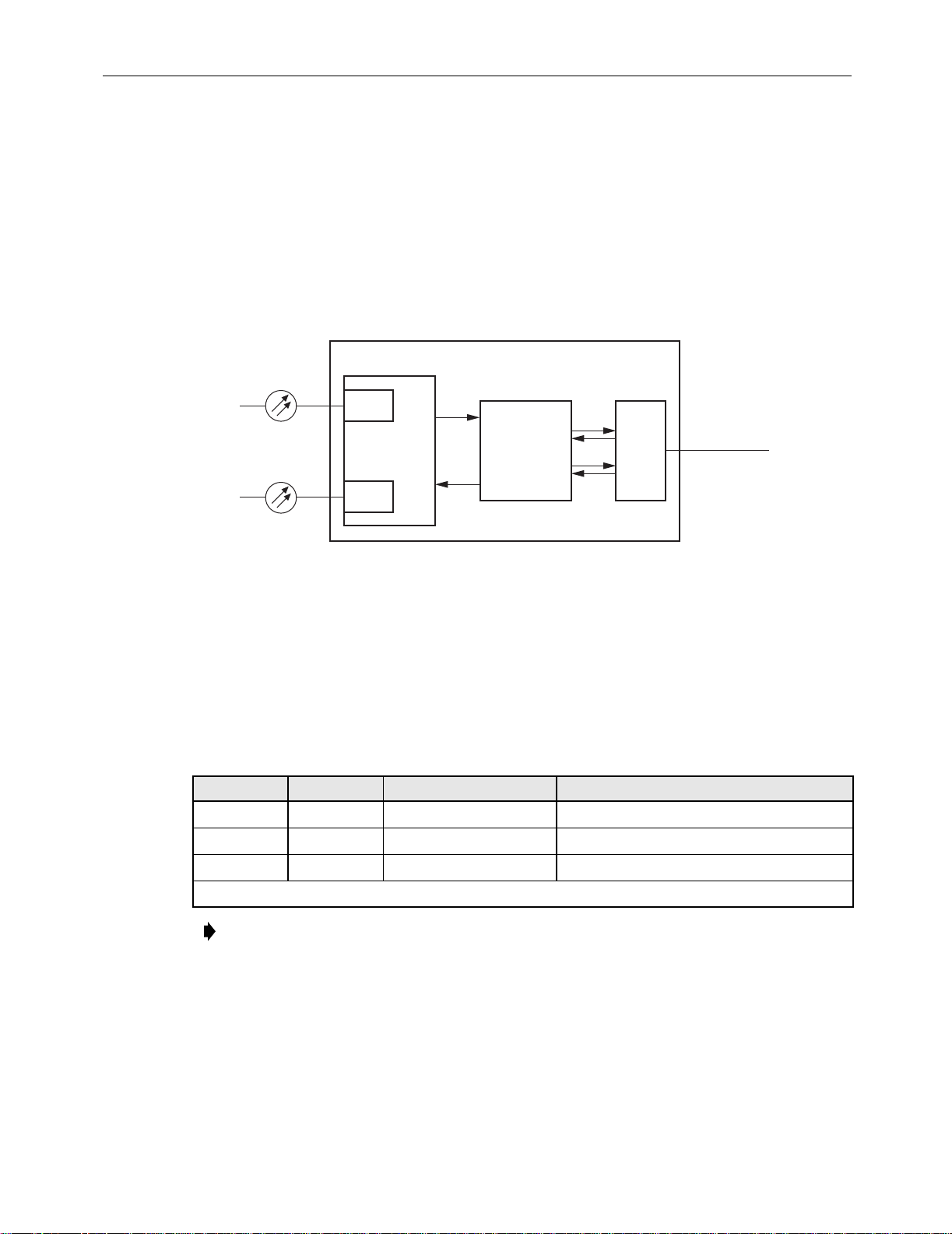
1 PRODUCT DESCRIPTION
The OptEnet 10/100 or 1000 Mb/s Media Converter with
Small Form-factor Pluggable (
SFP)
module is one of a family of modules that can be plugged into a OptEnet Media Converter
chassis. The module is designed to accept SFP transceivers with optical connectors. This
provides a number of optical signal choices. The module converts optical signals to electrical
signals. The module also performs the reverse function, converting electrical signals to optical
signals. A block diagram of the basic converter assembly is shown in Figure 1. Each module has
three connections fiber input, fiber output, and RJ45 Ethernet.
LED OR
LASER
FIBER CABLE
SFP
OPTICAL
TRANSCEIVER
PIN
ETHERNET
TRANSCEIVER
Figure 1. Basic Media Converter Block Diagram
RJ-45
20580-A
UTP CABLE
The OptEnet 10/100 Mb/s Media Converter module supports 10BaseT and 100BaseTX. The 1000
Mb/s Media Converter module supports 1000BaseT data rates with UTP cable.
cable specifications. Refer to the
Publications
NETWORK DATA RATE MEDIA LENGTH
10BaseT 10 Mb/s UTP Cat 3, 4, or 5 (2-pair) 328 feet (100 m)
100BaseTX 100 Mb/s UTP Cat 5 (2-pair) 328 feet (100 m)
1000BaseT Gigabit UTP Cat 5e (4-pair) 328 feet (100 m)
UTP = Unshielded Twisted Pair
1.1 Front Panel
Each module has three LEDs, a module power LED and two Link LEDs. Under normal
operation the module PWR LED is green. Front panel indicators and controls are defined in
Tab le 2 . A module is shown in Figure 2.
OptEnet SFP Transceiver Specifications
Table 1
listed in
lists the
Related
, for optical specifications.
Table 1. Cable Specifications
Note: The maximum cable length is the cable length that the signal can travel without
suffering from attenuation (degradation).
Page 4
© 2005, ADC Telecommunications, Inc.
Page 5

RJ45
CONNECTOR
OPTICAL
RECEIVE
OPTICAL
TRANSMIT
ADCP-92-063 • Issue 1 • May 2005
20460-A
Figure 2. OptEnet Media Converter Converter
Table 2. Module LED Indicators
SIGNAL COLOR STATUS
TP Link YELLOW Auto negotiation complete, link status 10 Mb/s is OK.
GREEN Auto negotiation complete, link status 100 Mb/s or 1000 Mb/s is OK.
OFF Link status failed or no Ethernet detected.
Link YELLOW Auto negotiation complete, link status 10 Mb/s is OK.
GREEN Auto negotiation complete, link status 100 Mb/s or 1000 Mb/s is OK.
OFF Signal detect de-asserted, link status FAIL.
PWR GREEN Module Power OK
OFF Module Power OFF
CONTROL DESCRIPTION
Reset If module supply voltage drops below a predetermined value the module shuts down,
pressing the reset button restarts the module.
Any blinking of a Link LED indicates auto-negotiation in process. If a Link LED continues to
blink for more than 30 seconds then the operation of the far end device (i.e., duplex and speed)
needs to be verified or changed.
© 2005, ADC Telecommunications, Inc.
Page 5
Page 6

ADCP-92-063 • Issue 1 • May 2005
2 UNPACKING AND INSPECTION
Caution: Electronic modules can be damaged by electrostatic discharge (ESD). To prevent this,
take the following precautions:
• Wear an anti-static-discharge wrist strap while handling modules.
• Place modules in anti-static packing material when transporting or storing them.
• Place modules on an approved, electrically grounded, anti-static mat when working on them.
Unpack and inspect the module as follows:
1. Inspect the exterior of the shipping container(s) for evidence of rough handling that may
have damaged the components in the container.
2. Unpack module, carefully checking it for damage and verify with the packing slip. If any
item is damaged, consult ADC for repair, replacement, and warranty information. Even
though no damage is evident, save the shipping container for use if the equipment requires
shipment at a future date.
3. File a claim with the commercial carrier and notify ADC Customer Service if damage is
detected or if parts are missing. Save damaged cartons for inspection by the carrier.
4. Refer to Customer Information and Assistance if you need to contact ADC.
5. Save all shipping containers for use if the equipment requires shipment at a future date.
3 INSTALLATION
3.1 1000 Mb/s Module
Each 1000 Mb/s module has a 2-position dip-switch for enabling or disabling the UTP
(Unshielded Twisted Pair) Link upon detection of the fiber optic link. Position 1 enables or
disables the UTP link independently of the fiber link. Position 2 reports the configuration to the
CPU through the backplane interface. Position 1 and position 2 must be set to the same positions.
If DIP switches are set to the ON position, then the UTP side follows the fiber side. For
example, if the fiber side links then the UTP side links also. If fiber side is not linked or loses
link, then UTP side is not allowed to link or will drop the link. If switch is configured to the
OFF position, then UTP link does not follow the fiber link. The UTP side links regardless of the
status of the fiber side. Tabl e 3 shows the dip-switch positions.
DIP SWITCH DESCRIPTION
1 ON = UTP Link dependent of Fiber Link
Table 3. 1000 Mb/s Dip-Switch Positions
OFF = UTP Link independent of Fiber Link (Default position)
2 ON = Reports to CPU the UTP Link dependent of Fiber Link
Page 6
© 2005, ADC Telecommunications, Inc.
OFF = Reports to CPU the UTP Link independent of Fiber Link (Default position)
Page 7

3.2 10/100 Mb/s Module
OptEnet Chassis should already be installed, power supplies installed, and power connections made
before installing OptEnet Media Converter with SFP Modules. Media converter module can be
safely removed and installed into a powered chassis. Module installation is shown in
ADCP-92-063 • Issue 1 • May 2005
Figure 3
.
20473-A
MEDIA
CONVERTER
MODULE
Figure 3. Installing Media Converter Module
1. Locate the designated slot in the chassis for the module.
Danger: To avoid the possibility of severe and potentially fatal electric shock, never install
electrical equipment in a wet location or during a lightning storm.
Caution: Electronic modules can be damaged by electrostatic discharge (ESD). To prevent this,
take the following precautions:
• Wear an anti-static-discharge wrist strap while handling modules.
• Place modules in anti-static packing material when transporting or storing them.
• Place modules on an approved, electrically grounded, anti-static mat when working on them.
2. Slide OptEnet media converter into slot and plug it into the connector on the backplane.
Modules can be plugged into any empty slot in the chassis. All fiber connectors are mounted
in straight retainers. The module is held in place with thumbscrew fasteners.
3. Secure the module in place by tightening the captive thumbscrews on each end. Be sure
that they are properly threaded before tightening.
4. If not already installed insert SFP into OptEnet media converter until you hear it click in place.
© 2005, ADC Telecommunications, Inc.
Page 7
Page 8

ADCP-92-063 • Issue 1 • May 2005
Caution: Always allow sufficient fiber length to permit routing without severe bends. Fibers
may be permanently damaged if bent/curved to a radius of less than 1.5 in. (3.81 cm).
Danger: Infrared radiation is invisible and can seriously damage the retina of the eye. Do not
look into the optical connector of an operational transmitter, or into the end of an active fiber. A
clean, protective cap or hood MUST be immediately placed over any radiating connector or
optical fiber to avoid exposure to potentially dangerous amounts of radiation. This practice also
helps prevent contamination of connectors and adapters. Do not assume laser power is turned
off or the fiber is disconnected at the other end.
5. Verify that the POWER LED is lit.
6. Remove the dust covers from fiber cable ends and from the media converter SFP.
7. Attach the fiber cable “TX” and “RX” connectors to the corresponding receptacles on the
media converter. See Figure 4.
RJ45
CONNECTOR
OPTICAL
RECEIVE
20460-A
OPTICAL
TRANSMIT
Figure 4. 10/100 Mb/s OptEnet Media Converter Module Connections
Caution: Ethernet signals over copper should not be used between buildings. Ground potential
differences may cause transmission errors or line card failures.
8. Each media converter module has an RJ45 connector located on the front. Use this
connector when making the copper Ethernet connection. RJ45 Patchcord pinout information
is shown in
Table 4
or
Tab le 5
and
Figure 5
.
a. Cat 5e or better RJ45 Patchcords are recommended.
Page 8
© 2005, ADC Telecommunications, Inc.
Page 9

ADCP-92-063 • Issue 1 • May 2005
b. The IEEE Standard ANSI/TIA-568-B for Ethernet 10/100BaseT(X) requires that two
twisted pairs be used and that one pair is connected to pins 1 and 2, and that the second
pair is connected to pins 3 and 6.
c. The IEEE Specification Standard ANSI/TIA-568-B for Ethernet 1000BaseT requires
that four twisted pairs are used. One pair is connected to pins 1 and 2, pair two is
connected to pins 3 and 6, pair three is connected to pins 4 and 5, and pair four is
connected to pins 7 and 8.
9. Connect Ethernet RJ45 patchcord to RJ45 receptacle on the converter module.
10. Verify that the front panel LEDs are active. Link LEDs are not lighted if there is no
Ethernet or optical signal present.
PIN 1
PIN 8
RJ-JACK
11899-A
Figure 5. RJ45 Connector Wiring
Table 4. 10/100BaseT(X) Ethernet RJ45 Connector
PIN # SIGNAL NAME FUNCTION PIN # SIGNAL NAME FUNCTION
1 TX+ Transmit Data 2 TX– Transmit Data
3 RX+ Receive Data 4 --- Not used
5 --- Not used 6 RX– Receive Data
7 --- Not used 8 --- Not used
Table 5. 1000BaseT Ethernet RJ45 Connector
PIN # SIGNAL NAME FUNCTION PIN # SIGNAL NAME FUNCTION
1 BD1+ Bidirectional 2 BD1– Bidirectional
3 BD2+ Bidirectional 4 BD3+ Bidirectional
5 BD3– Bidirectional 6 BD2– Bidirectional
7 BD4+ Bidirectional 8 BD4– Bidirectional
© 2005, ADC Telecommunications, Inc.
Page 9
Page 10

ADCP-92-063 • Issue 1 • May 2005
4 SPECIFICATIONS
Tab le 6 and Tab le 7 lists the specifications for the module.
PARAMETER SPECIFICATION REMARKS
Electrical
Input Voltage +5 VDC Backplane connector
Input power (10/100 Mb/s) 1.75 W max. Normal operation
Input power (1000 Mb/s) 2.2 W max. Normal operation
Mechanical
Chassis Compatibility OptEnet Media Converter All modular systems
Module Retention Captive thumbscrews
Table 6. Electrical and Mechanical Specifications
Dimensions
Weight 0.27 lb. (122 g.)
Electrical Signal Interface
RJ45 Two twisted pair 10/100 Mb/s
RJ45 Four twisted pair 1000 Mb/s
Optical Signal Interface
LC Singlemode 1410 – 1610 nm *
Refer to the OptEnet SFP Transceiver Specifications listed in Related Publications, for
* -
(H×W×D) 1.14 in.× 8.07 in.× 7.4 in.
optical specifications.
Table 7. Module Environmental Specifications
PARAMETER SPECIFICATION REMARKS
Operating Conditions 41°F to +104°F (5°C to +40°C) Per Telcordia GR-63
Short Term Conditions
Storage Conditions
+23°F to +122°F (−5°C to +50°C)
−40°F to +185°F (−40°C to +85°C) at 5% to 95% RH
5 POWER-UP/CHECK OUT PROCEDURE
(2.89 cm
×
20.5 cm × 18.8 cm)
Per Telcordia GR-63
Non-condensing
Media Converter Modules are powered up as soon as power is applied to the chassis. The
POWER indicator (GREEN LED) on the converter module should light to indicate that VDC
power is applied to the media converter. If POWER indicator does not come on, verify that
power connections between the Media Converter Module and the power supply are secure.
Verify that there is power present at the source. If this procedure does not resolve the problem,
replace the cable or power supply.
Page 10
© 2005, ADC Telecommunications, Inc.
Page 11

OptEnet Media Converter with SFP modules support Medium Dependent Interface Crossover
(MDI-X). OptEnet Media Converter Module Ethernet ports allow connections to other hubs or
switches without a null-modem or crossover cable. If a null-modem or crossover cable has been
used the OptEnet Media Converter with SFP module automatically detects this and switches the
contacts to match the other end.
Any blinking of a link LED indicates auto-negotiation in process. If a link LED continues to
blink for more than 30 seconds then the operation of the far end device (i.e., duplex and speed)
needs to be verified or changed.
5.1 10/100 Mb/s Module
If the PC workstation port has been set to auto-select (i.e., full auto-negotiation) for speed and
duplex, the TPLink LED will be OFF when power is applied unless a valid optical link has
already been established with a remote optical port. If a valid optical link has been established,
FOLink LED will be YELLOW for 10 Mb/s operation or GREEN for 100 Mb/s operation. The
preferred mode of operation for the port is auto select for both speed and duplex. This will
insure that a link can be established regardless of the far end operational mode.
ADCP-92-063 • Issue 1 • May 2005
OptEnet 10/100BaseLX Media Converters support auto-negotiation as defined in TIA/EIA-785.
Auto-negotiation allows the unit to automatically select the highest performance level for
COPPER or FIBER.
5.2 1000 Mb/s Module
Set data rate speed to
connected to the OptEnet 1000 Mb/s Media Converter module.
If the Network Interface Card (NIC) or port in the PC workstation has been set to 1000 Mb/s for
speed and half/full duplex auto-negotiate, the link LED will be OFF when power is applied.
Once valid optical and electrical links have been established, link LEDs turn GREEN.
6 OPERATION
The Module may be controlled through a Command Line Interface. Refer to the OptEnet Media
Converter Communications User Manual listed in Related Publications, for operational
procedures that pertain to the CPU module.
7 MAINTENANCE
1000 Mb/s and enable half/full duplex auto-negotiate
on any equipment
Follow standard cleaning practices for maintenance of fiber adapters and connectors.
© 2005, ADC Telecommunications, Inc.
Page 11
Page 12

ADCP-92-063 • Issue 1 • May 2005
8 TROUBLESHOOTING
This section provides a troubleshooting flowchart, and corrective actions for the Module.
Power-up the
Media Converter Module
by plugging it into the
Chassis.
Does the
1.
Link Green 100 Mb/s or 1000 Mb/s signal asserted.
TPLink Green 100 Mb/s or 1000 Mb/s signal asserted.
PWR LED on
Media Converter
Module light?
YES
2.
Do both Media
Converter Module
Link LEDs light?
YES
Link Yellow 10 Mb/s signal asserted.
TPLink Yellow 10 Mb/s signal asserted.
Module is operating properly, signal
detect is asserted and link status is OK.
NO
Pull out and insert the
Media Converter Module
into the slot so the backplane
connector seats properly.
NO
Check optical or copper path for signal.
Repair as necessary following local practices.
Press the reset button, if the PWR LED does
not turn green the module may be defective.
Replace the Media Converter Module
If either Link LED is off, link status
failed or no Ethernet is detected.
20579-A
Does the
PWR LED on
Media Converter
Module light?
NO
with a known good module.
Page 12
© 2005, ADC Telecommunications, Inc.
Page 13

9 CUSTOMER INFORMATION AND ASSISTANCE
PHONE:
EUROPE
Sales Administration: +32-2-712-65 00
Technical Assistance: +32-2-712-65 42
EUROPEAN TOLL FREE NUMBERS
Germany:
UK:
Spain:
France:
Italy: 0800 782374
U.S.A. OR CANADA
Sales: 1-800-366-3891 Extension 73000
Technical Assistance: 1-800-366-3891
Connectivity Extension 73475
Wireless Extension 73476
ASIA/PACIFIC
Sales Administration: +65-6294-9948
Technical Assistance: +65-6393-0739
ELSEWHERE
Sales Administration: +1-952-938-8080
Technical Assistance: +1-952-917-3475
WRITE:
ADC TELECOMMUNICATIONS, INC
PO BOX 1101,
MINNEAPOLIS, MN 55440-1101, USA
0180 2232923
0800 960236
900 983291
0800 914032
ADCP-92-063 • Issue 1 • May 2005
ADC TELECOMMUNICATIONS (S'PORE) PTE. LTD.
100 BEACH ROAD, #18-01, SHAW TOWERS.
SINGAPORE 189702.
ADC EUROPEAN CUSTOMER SERVICE, INC
BELGICASTRAAT 2,
1930 ZAVENTEM, BELGIUM
PRODUCT INFORMATION AND TECHNICAL ASSISTANCE:
connectivity.tac@adc.com
wireless.tac@adc.com
euro.tac@adc.com
asiapacific.tac@adc.com
Contents herein are current as of the date of publication. ADC reserves the right to change the contents without prior notice.
In no event shall ADC be liable for any damages resulting from loss of data, loss of use, or loss of profits and ADC further
disclaims any and all liability for indirect, incidental, special, consequential or other similar damages. This disclaimer of
liability applies to all products, publications and services during and after the warranty period. This publication may be
verified at any time by contacting ADC's Technical Assistance Center.
© 2005, ADC Telecomm uni cations, Inc.
13944-M
All Rights Re s erved
Printed in U.S.A.
Page 13
 Loading...