

Page 1
Solar LED L-858Y/R/L/B Signs
Light Bar Signs with SEPS Power
User Manual
96A0492, Rev. A, 9/8/17
Page 2

Solar LED L-858Y/R/L/B Signs
DISCLAIMER / WARRANTY
a.0 Disclaimer / Standard Warranty
a.1 CE certification
The equipment listed as CE certified means that the product complies with the essential requirements concerning safety and
hygiene. The directives that have been taken into consideration in the design are available on written request to ADB SAFEGATE.
a.2 ETL certification
The equipment listed as ETL certified means that the product complies with the essential requirements concerning safety and FAA
Airfield regulations. The directives that have been taken into consideration in the design are available on written request to
ADB SAFEGATE.
a.3 LED Product Guarantee
Where applicable, per FAA EB67(applicable edition), ADB SAFEGATE L858(L) Airfield Guidance Signs are warranted against
electrical defects in design or manufacture of the LED or LED specific circuitry for a period of 4 years. ADB SAFEGATE LED light
fixtures (with the exception of obstruction lighting) are warranted against mechanical and physical defects in design or
manufacture for a period of 12 months from date of installation; and are warranted against electrical defects in design or
manufacture of the LED or LED specific circuitry for a period of 4 years per FAA EB67 (applicable edition).
NOTE: See your sales order contract for a complete warranty description. In some specific cases, deviations are (to be) accepted in
the contract, which will supersede the standard warranty.
a.4 Standard Product Guarantee
Products of ADB SAFEGATE manufacture are guaranteed against mechanical, electrical, and physical defects (excluding lamps)
which may occur during proper and normal use for a period of one year from the date of installation or 2 years from date of
shipment and are guaranteed to be merchantable and fit for the ordinary purposes for which such products are made. ADB
SAFEGATE L858 Airfield Guidance Signs are warranted against mechanical and physical defects in design or manufacture for a
period of 2 years from date of installation per FAA AC 150/5345-44 (applicable edition).
NOTE: See your sales order contract for a complete warranty description.
a.5 All Products
LED Products of ADB SAFEGATE, manufactured and sold by ADB SAFEGATE or its licensed representatives, meets the
corresponding requirements of FAA, ICAO and IEC.
ADB SAFEGATE will correct by repair or replacement per the applicable guarantee above, at its option, equipment or parts which
fail because of mechanical, electrical or physical defects, provided that the goods have been properly handled and stored prior to
installation, properly installed and properly operated after installation, and provided further that Buyer gives ADB SAFEGATE
written notice of such defects after delivery of the goods to Buyer. Refer to the Safety section for more information on Material
Handling Precautions and Storage precautions that must be followed.
ADB SAFEGATE reserves the right to examine goods upon which a claim is made. Said goods must be presented in the same
condition as when the defect therein was discovered. ADB SAFEGATE furthers reserves the right to require the return of such
goods to establish any claim.
ADB SAFEGATE’s obligation under this guarantee is limited to making repair or replacement within a reasonable time after receipt
of such written notice and does not include any other costs such as the cost of removal of defective part, installation of repaired
product, labor or consequential damages of any kind, the exclusive remedy being to require such new parts to be furnished.
ADB SAFEGATE’s liability under no circumstances will exceed the contract price of goods claimed to be defective. Any returns
under this guarantee are to be on a transportation charges prepaid basis. For products not manufactured by, but sold by ADB
SAFEGATE, warranty is limited to that extended by the original manufacturer.
This is ADB SAFEGATE’s sole guarantee and warranty with respect to the goods; there are no express warranties or warranties of
fitness for any particular purpose or any implied warranties of fitness for any particular purpose or any implied warranties other
than those made expressly herein. All such warranties being expressly disclaimed.
96A0492 Rev. A
ii
© ADB Safegate All Rights Reserved
Page 3
Solar LED L-858Y/R/L/B Signs
DISCLAIMER / WARRANTY
a.6
Liability
WARNING
Use of the equipment in ways other than described in the catalogue leaflet and the manual may result in
personal injury, death, or property and equipment damage. Use this equipment only as described in the
manual.
ADB SAFEGATE cannot be held responsible for injuries or damages resulting from non-standard, unintended uses of its
equipment. The equipment is designed and intended only for the purpose described in the manual. Uses not described in the
manual are considered unintended uses and may result in serious personal injury, death or property damage.
Unintended uses includes the following actions:
— Making changes to equipment that have not been recommended or described in this manual or using parts that are not
genuine ADB SAFEGATE replacement parts or accessories.
— Failing to make sure that auxiliary equipment complies with approval agency requirements, local codes, and all applicable
safety standards if not in contradiction with the general rules.
— Using materials or auxiliary equipment that are inappropriate or incompatible with your ADB SAFEGATE equipment.
—
Allowing unskilled personnel to perform any task on or with the equipment.
© ADB Safegate All Rights Reserved
96A0492 Rev. A
iii
Page 4

Solar LED L-858Y/R/L/B Signs
DISCLAIMER / WARRANTY
a.7 © ADB SAFEGATE BVBA
This manual or parts thereof may not be reproduced, stored in a retrieval system, or transmitted, in any form or by any means,
electronic, mechanical, photocopying, recording, nor otherwise, without ADB SAFEGATE BVBA’s prior written consent.
This manual could contain technical inaccuracies or typographical errors. ADB SAFEGATE BVBA reserves the right to revise this
manual from time to time in the contents thereof without obligation of ADB SAFEGATE BVBA to notify any person of such revision
or change. Details and values given in this manual are average values and have been compiled with care. They are not binding,
however, and ADB SAFEGATE BVBA disclaims any liability for damages or detriments suffered as a result of reliance on the
information given herein or the use of products, processes or equipment to which this manual refers. No warranty is made that the
use of the information or of the products, processes or equipment to which this manual refers will not infringe any third party’s
patents or rights. The information given does not release the buyer from making their own experiments and tests.
96A0492 Rev. A
iv
© ADB Safegate All Rights Reserved
Page 5
Solar LED L-858Y/R/L/B Signs
TABLE OF CONTENTS
a.0: Disclaimer / Standard Warranty .............................................................................................................II
1.0: Safety ...................................................................................................................................................................... 1
1.1 :Introduction ................................................................................................................................................. 1
1.2 :To use this equipment safely: .................................................................................................................. 1
1.3 :Additional Reference Materials: .............................................................................................................. 1
1.4 :Qualified Personnel .................................................................................................................................... 1
1.5 :Intended Use ............................................................................................................................................... 1
1.6 :Storage .......................................................................................................................................................... 2
1.7 :Operation ..................................................................................................................................................... 2
1.8 :Material Handling Precautions ................................................................................................................ 2
1.9 :Action in the Event of a System or Component Malfunction ......................................................... 2
1.10 :Maintenance and Repair ........................................................................................................................ 3
2.0: Introduction ........................................................................................................................................................5
2.1 :Compliance with Standards ..................................................................................................................... 5
2.1.1 :Uses .......................................................................................................................................................................5
2.2 :General Information ................................................................................................................................... 5
2.2.1 :Features ................................................................................................................................................................5
2.2.2 :Operating Conditions ........................................................................................................................................6
2.2.3 :Construction ........................................................................................................................................................6
2.2.4 :Installation ............................................................................................................................................................6
2.2.5 :Solar Panel Orientation .....................................................................................................................................6
© ADB Safegate All Rights Reserved
96A0492 Rev. A
v
Page 6
Solar LED L-858Y/R/L/B Signs
2.3 :Equipment Data .......................................................................................................................................... 7
2.3.1 :Solar Engine Power Supply (SEPS) .................................................................................................................7
2.3.2 :Sign Dimensions .................................................................................................................................................8
2.3.3 :Packaging Data ...................................................................................................................................................8
2.4 :Wireless Hand-Held Controller ............................................................................................................... 9
2.4.1 :Features .................................................................................................................................................................9
2.5 :Solar Regions ............................................................................................................................................. 10
2.5.1 :Solar Panel Orientation .................................................................................................................................. 10
2.5.2 :Theory of Operation .......................................................................................................................................11
2.5.3 :TILT ANGLES .....................................................................................................................................................13
3.0: Installation .........................................................................................................................................................15
3.1 :Unpacking ..................................................................................................................................................15
3.2 :Cord Set Installation .................................................................................................................................16
3.2.1 :Cord Set Installation Reference Number ...................................................................................................16
3.2.2 :Cord set and Extension Cords ...................................................................................................................... 19
3.3 :General Guidelines ................................................................................................................................... 21
3.3.1 :Overall Mounting Height ............................................................................................................................... 21
3.3.2 :Sign Orientation ...............................................................................................................................................21
3.3.3 :Sign Distance from Pavement Edge ........................................................................................................... 21
3.3.4 :Sign Installation on a Concrete Pad ............................................................................................................21
3.3.5 :Sign Mounting ..................................................................................................................................................24
3.4 :SEPS Installation ........................................................................................................................................24
3.4.1 :Site Preparation ................................................................................................................................................24
3.4.2 :Assembly ............................................................................................................................................................25
3.4.3 :Antenna Assembly ...........................................................................................................................................26
3.4.4 :Grounding .........................................................................................................................................................27
3.4.5 :Connect Load ................................................................................................................................................... 28
3.4.6 :Install Battery ..................................................................................................................................................... 28
3.4.7 :Wiring ................................................................................................................................................................. 31
3.4.8 :Earth Ground Lug ............................................................................................................................................ 31
3.4.9 :Sign Fastener Installation ...............................................................................................................................31
96A0492 Rev. A
vi
© ADB Safegate All Rights Reserved
Page 7

Solar LED L-858Y/R/L/B Signs
3.4.10 :Optional Tethers ............................................................................................................................................31
4.0: Maintenance and Repair............................................................................................................................33
4.1 :Replacing an LED Light Bar .................................................................................................................... 33
4.2 :Batteries ...................................................................................................................................................... 34
4.2.1 :Energy Management System (EMS) Recycling .........................................................................................34
4.3 :Troubleshooting ....................................................................................................................................... 36
5.0: Parts/Ordering Codes..................................................................................................................................39
5.1 :Spare Components .................................................................................................................................. 42
© ADB Safegate All Rights Reserved
96A0492 Rev. A
vii
Page 8

Solar LED L-858Y/R/L/B Signs
96A0492 Rev. A
viii
© ADB Safegate All Rights Reserved
Page 9
1.0 Safety
1.1 Introduction
This section contains general safety instructions for installing and using ADB Safegate, Americas equipment. Some safety
instructions may not apply to the equipment in this manual. Task- and equipment-specific warnings are included in other sections
of this manual where appropriate.
Carefully read and observe all safety instructions in this manual, which alert you to safety hazards and conditions that may result
in personal injury, death or property and equipment damage and are accompanied by the symbol shown below.
1.2 To use this equipment safely:
WARNING
Read installation instructions in their entirety before starting installation.
• Refer to the FAA Advisory Circular AC 150/5340-26, Maintenance of Airport Visual Aids Facilities, for instructions
on safety precautions.
• Observe all safety regulations.
• Become familiar with the general safety instructions in this section of the manual before installing, operating,
maintaining or repairing this equipment.
• Read and carefully follow the instructions throughout this manual for performing specific tasks and working with
specific equipment.
• Make this manual available to personnel installing, operating, maintaining or repairing this equipment.
• Follow all applicable safety procedures required by your company, industry standards and government or other
regulatory agencies.
• Protect equipment with safety devices as specified by applicable safety regulations.
1.3 Additional Reference Materials:
• NFPA 70B, Electrical Equipment Maintenance
• NFPA 70E, Electrical Safety Requirements for Employee Workplaces
• ANSI/NFPA 79, Electrical Standards for Metalworking Machine Tools
• OSHA 29 CFR, Part 1910, Occupational Health and Safety Standards
• National and local electrical codes and standards.
1.4 Qualified Personnel
The term qualified personnel is defined here as individuals who thoroughly understand the equipment and its safe operation,
maintenance and repair. Qualified personnel are physically capable of performing the required tasks, familiar with all relevant
safety rules and regulations and have been trained to safely install, operate, maintain and repair the equipment. It is the
responsibility of the company operating this equipment to ensure that its personnel meet these requirements.
Always use required personal protective equipment (PPE) and follow safe electrical work practices. See 1.2 above.
1.5 Intended Use
WARNING
Using this equipment in ways other than described in this manual may result in personal injury, death or property
and equipment damage. Use this equipment only as described in this manual.
ADB Safegate, Americas cannot be responsible for injuries or damages resulting from nonstandard, unintended applications of its
equipment. This equipment is designed and intended only for the purpose described in this manual. Uses not described in this
manual are considered unintended uses and may result in serious personal injury, death or property and equipment damage.
Unintended uses may result from taking the following actions:
• Using materials or auxiliary equipment that are inappropriate or incompatible with ADB Safegate, Americas equipment
• Allowing unqualified personnel to perform any task
© ADB Safegate All Rights Reserved
1
Page 10
Solar LED L-858Y/R/L/B Signs
Storage
1.6 Storage
If equipment is to be stored prior to installation, it must be unboxed and set in a sunny area until needed.
Failure to follow this instruction can result in battery damage.
1.7 Operation
• Only qualified personnel, physically capable of operating the equipment and with no impairments in their
judgment or reaction times, should operate this equipment.
• Read all system component manuals before operating this equipment. A thorough understanding of system
components and their operation will help you operate the system safely and efficiently.
• Protect equipment with safety devices as specified by applicable safety regulations.
• If safety devices must be removed for installation, install them immediately after the work is completed and check
them for proper functioning.
• Never operate equipment with a known malfunction.
• Use this equipment only in the environments for which it is rated. Do not operate this equipment in humid,
flammable, or explosive environments unless it has been rated for safe operation in these environments.
• Never touch exposed electrical connections on equipment while the power is ON.
CAUTION
WARNING
1.8 Material Handling Precautions
CAUTION
This equipment may contain electrostatic sensitive devices.
• Protect from electrostatic discharge.
• Electronic modules and components should be touched only when this is unavoidable e.g. soldering,
replacement.
• Electronic modules or components must not be brought in contact with highly insulating materials such as plastic
sheets, synthetic fiber clothing. They must be laid down on conductive surfaces.
• The tip of the soldering iron must be grounded.
• Electronic modules and components must be stored and transported in conductive packing.
1.9 Action in the Event of a System or Component Malfunction
WARNING
• Do not operate a system that contains malfunctioning components. If a component malfunctions, turn the system
OFF immediately.
• Allow only qualified personnel to make repairs. Repair or replace the malfunctioning component according to
instructions provided in its manual.
2
96A0492 Rev. A
© ADB Safegate All Rights Reserved
Page 11
1.10 Maintenance and Repair
Allow only qualified personnel to perform maintenance, troubleshooting, and repair tasks.
• Only persons who are properly trained and familiar with ADB Safegate, Americas equipment are permitted to
service this equipment.
• Always use safety devices when working on this equipment.
• Follow the recommended maintenance procedures in your equipment manuals.
• Use only approved ADB Safegate, Americas replacement parts. Using unapproved parts or making unapproved
modifications to equipment may void agency approvals and create safety hazards.
WARNING
© ADB Safegate All Rights Reserved
3
Page 12

Solar LED L-858Y/R/L/B Signs
Maintenance and Repair
4
96A0492 Rev. A
© ADB Safegate All Rights Reserved
Page 13
2.0 Introduction
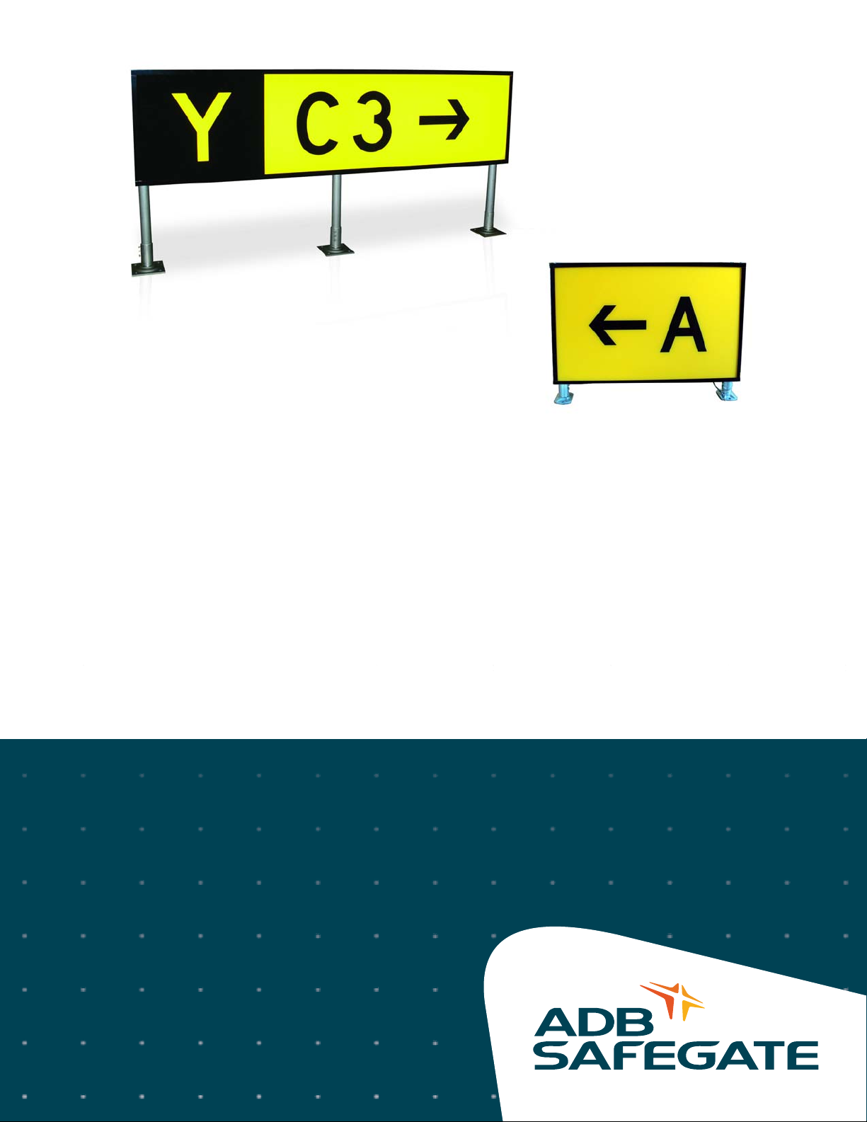
These signs are designed to guide pilots to a particular point on the field, identify holding positions, identify taxiway and runway
intersections, and prohibit aircraft entry into designated areas.
2.1 Compliance with Standards
FAA:
Designed to meet L-858Y, L-858R L-858L and L-858B AC 150/5345-44 (Current Edition) and the FAA Engineering Brief No. 67
“Light Sources other than Incandescent and Xenon for Airport Lighting and Obstruction Lighting Fixtures.”
CE:
Complies with the requirements of the EMC Directive 2004/108/EC
2.1.1 Uses
ADB Safegate’s LED Solar Sign System (SSS) is an ideal choice for an airfield that requires improved safety measures, but
experiences difficulties with grid access. ADB Safegate’s SSS consists of an L-858Y, L-858R, L-858L, L-858B solar-powered sign (SS)
and a Solar Engine Power Supply (SEPS). The SEPS incorporates the latest technology in solar technology, hardware and software
to provide power and control to the SS.
• L-858Y SS: Direction, Destination, and Boundary (Informational Sign)
• L-858R SS: Mandatory Sign
• L-858L SS: Runway/Taxiway Location Sign
These signs are designed to guide pilots to a particular point on the field, identify holding positions, identify taxiway and
runway intersections, and prohibit aircraft entry into designated areas.
• L-858B SS: Runway Distance Remaining Sign
The L-858B SS is used at 1,000-foot intervals adjacent to the runway edge in order to provide runway distance remaining
information to pilots during takeoff and landing operations.
2.2 General Information
Table 1: Sign Legends
Type Purpose Legend Color Background Color
L-858Y Direction, Destination & Boundary Black Yellow
L-858R Mandatory Sign White with Black Outline Red
L-858L Runway/Taxiway Location Yellow Black
L-858B Runway Distance Remaining White Black
2.2.1 Features
•
Virtually eliminates runway shutdowns due to LED light source
• Direct replacement for existing sign
• Creates a highly uniform distribution of light, eliminating hot spots and shadows
• Operates on solar energy
• Eliminates re-lamping expenses and reduces on-going maintenance costs
• The SSS installs in minutes with no trenching, cabling, or external power, and can be relocated just as quickly.
• Battery daily depth of discharge is sized for a minimum of 5 years of service.
• Unprecedented reliability: microprocessor Energy Management System (EMS) monitors and adapts the brightness to
environmental conditions for consistent operation and long life under the toughest conditions.
• The minimum autonomy or operational period without charging is 7 days.
• Protect personnel and assets: Optional hand-held wireless control allows for remote operation of a solar sign including mode
changes for enhanced visibility in poor weather conditions
• Green solution: a clean, renewable and reliable energy source with the lightest environmental footprint.
© ADB Safegate All Rights Reserved
5
Page 14
Solar LED L-858Y/R/L/B Signs
B7 B7
Direct Mounting
Remote Mounting (recommended)
1
1
2345
6
7
3
7 8
General Information
2.2.2 Operating Conditions
Temperature: -40 °F to +131 °F (-40 °C to +55 °C)
Humidity: 0 to 100%
Wind: Mode 2 signs withstand wind velocities up to 225 mph
2.2.3 Construction
Corrosion-resistant sign construction requires minimal maintenance.
— Aluminum housing
— Acrylic sign legend panels
— Stainless steel hardware
— Retroreflective sheeting
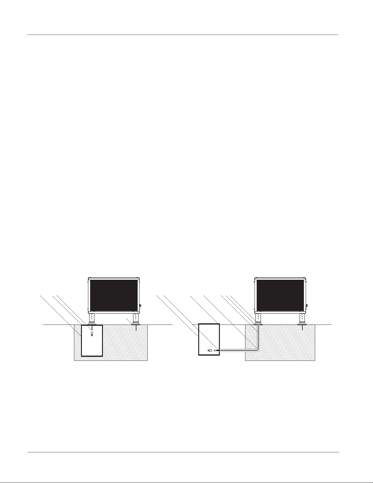
2.2.4 Installation
For a temporary application, the wiring between the SEPS and the SS can be above ground. Both the SS and SEPS contain side
conduits for cabling access.
Each sign is furnished complete with mounting flanges for installation on a concrete pad, which is the recommended method of
installation. Contact the ADB Safegate Sales Department for more information on sign installation hardware.
1. L-823 Cord Set (supplied with the sign)
2. Cable Clamp (supplied with the sign)
3. Floor Flange (supplied with the sign)
4. 2-inch Conduit Elbow (contractor supplied)
5. L-867 Blank Cover Plate with Gasket (purchased separately)
6. Cable from SEPS
7. L-867 Base (purchased separately)
8. L-867 Base Plate (special - purchased separately)
Figure 1: Direct/Remote Mounting
2.2.5 Solar Panel Orientation
Full solar exposure is critical to the performance of the SSS. Ensure that the SEPS installation location has year-round, unrestricted
sun exposure throughout the day. The bottom edge of the solar panels should be installed at a minimum height to clear growing
vegetation and snow at the site.
NOTE: Shading even a small portion of the solar panel will significantly reduce the output of the SSS.
6
96A0492 Rev. A
© ADB Safegate All Rights Reserved
Page 15
2.3 Equipment Data
2.3.1 Solar Engine Power Supply (SEPS)
Table 2: Specifications
Installed weight 132 lb (59.8 kg)
Shipping weight
Installed dimensions*
Box 1 (SEPS)
Box 2 (battery)
Operating: -22
Storage: -40 °F to +176 °F (-40 °C to +80 °C)
Box 1 (SEPS) - 76 lb (34.4 kg)
Box 2 (battery) - 68 lb (30.8 kg)
29.9 H x 42.9 W x 17.4 D in
(75.9 H x 108.9 W x 44.1 D cm)
* with wireless antenna at 55° tilt
Shipping dimensions
25.5 H x 46.9 W x 14.0 D in
(64.7 H x 119.1 W x 35.56 D cm)
8.3 H x 13.1 W x 7.4 D in
(21 H x 33.2 W x 18.8 D cm)
Temperature
°F to +122 °F (-30 °C to +50 °C)
Chassis
Mounting ADB Safegate frangible couplings and floor flange mounts
Wind loading 300 mph min. installed at 55° tilt
Tilt 15°, 35°, 55°
Diagnostics
Certifications RoHS, WEEE, CE, FCC
Power 12 VDC 105 A-hr at C/100 discharge rate
Type Replaceable and recyclable, absorbent glass mat (AGM) SLA. Standard with one battery.
Lifetime 4,000 cycles to 20% depth of discharge at +68
Charger Temperature-compensated, maximum power point tracking (TC-MPPT)
Channel A:
Channel B:
Automatic Light Control (ALC)
Control, Autonomous Mode Dusk-to-dawn, steady on
Load Cabling 22 ft. (6.7 m) cable can exit onto the surface or down into a ground pot
Power 17 VDC, 95 W
Type High Efficiency Monocrystalline, IEC 61215
Weather and corrosion-resistant construction of stainless steel and powder coated
aluminum
On-board feedback indicators for:
Battery Status, System Status, Battery
Reverse Polarity, and Solar Panel
Reverse Polarity
Battery
°F
LED Driver
Power
18 – 38 VDC from 0.3 – 1.4 A and
5 – 100% duty cycle, constant current
18 – 38 VDC from 0.3 – 1.4 A and
5 – 100% duty cycle, constant current
ALC dynamically reduces brightness in response to unusually low amounts of sunlight to
ensure continued autonomous operation. Available on Channels A and B.
PV Panel (
© ADB Safegate All Rights Reserved
7
Page 16
Solar LED L-858Y/R/L/B Signs
Equipment Data
Lifetime 10 years at 90% output
Wireless
Range 2.5 miles minimum with 1 W wireless hand-held controller
Frequency 900 MHz ISM Band (902 – 928 MHz), FHSS
Encryption 256-bit AES
Seamless integration with existing ADB Safegate wireless solar products.
Up to 8 independent groups.
Control, On-demand Mode
Flash Mode, Emergency Mode, Autonomous Mode
On-demand Temporary Mode (High, Medium, and Low)
Configuration Mode, ARCAL
2.3.2 Sign Dimensions
Table 3: Sign Heights
Type Sign Size No. Sign Face Height Legend Height Overall Mounting Height
L-858Y/R/L 1 18” (45.7 cm) 12” (30.5 cm) 29.7” (75.5 cm)
L-858Y/R/L 2 24” (61 cm) 15” (38.1) 35.7” (90.8 cm)
L-858Y/R/L 3 30” (76.2 cm) 18” (45.7 cm) 41.7” (106 cm)
L-858B 4 48” (122 cm) 40” (101.6 cm) 58.2” (147.8 cm)
L-858B 5 30” (76.2 cm) 25” (63.5 cm) 41.7” (106 cm)
Table 4: Sign Lengths
Size No. 1 Module 2 Module
1 29.4” (75 cm) 58.6” (149 cm)
2 35.9” (91 cm) 71.6” (182 cm)
3 42.4” (108 cm) 84.6” (215 cm)
4 47.9” (122 cm) N/A
5 42.4” (108 cm) N/A
Note: Sign depth is 9.39 in (23.85 cm).
2.3.3 Packaging Data
Signs are shipped with L-823 cord set(s), frangible couplings, and floor flanges–ready for installation.
Table 5: Packaging Dimensions and Weights
Gross Weight
Description (lb) (kg) (in) (cm)
Size 1, Module 1 46 21 34 x 34 x 13 87 x 86.4 x 33
Size 1, Module 2 78 35 34 x 63 x 13 87 x 160 x 33
Size 2, Module 1 71 32 40 x 40 x 13 102 x 102 x 33
Size 2, Module 2 104 47 40 x 76 x 13 102 x 193 x 33
Size 3, Module 1 81 37 46 x 46 x 13 117 x 117 x 33
Size 3, Module 2 131 60 46 x 89 x 13 117 x 226 x 33
Size 4, Module 1 120 561 62 x 52 x 13 158 x 132 x 33
Size 5, Module 1 85 39 46 x 46 x 13 117 x 117 x 33
1
Estimated weight
1
Carton Dimensions
8
96A0492 Rev. A
© ADB Safegate All Rights Reserved
Page 17

2.4 Wireless Hand-Held Controller
SEPS can be controlled using the Wireless Hand-Held Controller in a similar manner to ADB Safegate’s wireless solar lights.
One or more wireless solar lights can be remotely operated from the ground or air with a hand-held wire-less controller using a
secure radio transceiver with antenna and keypad.
The hand-held remote control option allows the user to temporarily override the intensity set in the autonomous modes. In
temporary mode, 10%, 30% and 100%
intensities can be selected for a 15-minute Time-Out or a Maximum Time-Out.
The 15-minute Time-Out option is for only momentary intensity brightness operations of the SSS for airports that actively manage
their airfields. After 15 minutes, the SSS will be return to the autonomous configuration.
The Maximum Time-Out option is for airports that require “the most intensity for as long as possible.” The SEPS software prevents
the battery from being ON indefinitely at the chosen intensity, thereby preventing battery full discharge. To determine the
maximum activation time for each selected intensity and region, see Table 1.
2.4.1 Features
— Water-resistant keypad and LED indicators
— Utilizes a secure wireless RF signal
— Control range of up to 2.5 miles
— Meets MIL-SPEC-810E environmental requirements
— 24-hour operation on a single charge
— Rechargeable lithium-ion battery (included); recharges via an AC/DC wall plug (included)
— Compatible with stand-alone aviation ba nd VH F recei ver
— Comes complete in a custom Pelican™ case
© ADB Safegate All Rights Reserved
9
Page 18

Solar LED L-858Y/R/L/B Signs
Solar Regions
2.5 Solar Regions
Table 6: Maximum Activation Time for Selected Intensity and Region
On-Demand Activation Time
SSS Region
per Day, 100% Intensity
(meets FAA photometrics)
1 4 hrs 12 hrs 24 hrs
2 4 hrs 14 hrs 24 hrs
Size 1,2,3,5
1 Module
3 6 hrs 18 hrs 24 hrs
4 6 hrs 20 hrs 24 hrs
5 6 hrs 22 hrs 24 hrs
Size 4
1 Module
1 2 hrs 6 hrs 18 hrs
2 2 hrs 7 hrs 22 hrs
3 3 hrs 9 hrs 24 hrs
Size 1,2,3
2 Modules
4 3 hrs 10 hrs 24 hrs
5 3 hrs 11 hrs 24 hrs
Table 7: Autonomous Settings by Solar Region
SSS Region Autonomous Dusk-to-Dawn % Intensity
122%
230%
Size 1,2,3,5
1 Module
336%
450%
564%
Size 4
1 Module
111%
215%
318%
Size 1,2,3
2 Modules
425%
532%
Note: See catalog sheet 3036 in the Solar Product Center on our website for solar region maps in full color. If solar region is
unclear, please contact the ADB Safegate Sales Department.
On-Demand Activation Time
per Day, 30% Intensity
On-Demand Activation
Time per Day, 10% Intensity
2.5.1 Solar Panel Orientation
Full solar exposure is critical to the performance of the SWCS. Ensure that the SEPS installation location has year-round,
unrestricted sun exposure throughout the day. The bottom edge of the solar panels should be installed at a minimum height to
clear growing vegetation and snow at the site.
NOTE: Shading even a small portion of the solar panel will significantly reduce the output of the SWCS.
10
96A0492 Rev. A
© ADB Safegate All Rights Reserved
Page 19

2.5.2 Theory of Operation
The ADB Safegate SEPS is factory configured to work autonomously for either dusk-to-dawn or for
24-hour period operation. On autonomous mode the product turns on at the intensity that is sustainable in that solar region. See
Table 8 and Figure 2 for % intensity by solar region.
SEPS has the option to be controlled remotely with a Hand Held Radio Control. The wireless handheld controller allows for
intensity adjustment, some configuring, and grouping of loads. One of the benefits of radio controller is that the user can
temporary override the autonomous intensity factory settings. However there is a limitation on the amount of hours the SRGLS
can operate at different intensities.
SEPS can be controlled using the Wireless Hand-Held Controller in a similar manner to ADB Safegate’s wireless solar lights.
One or more wireless solar lights can be remotely operated from the ground or air with a hand-held wireless controller using a
secure radio transceiver with antenna and keypad.
The hand-held remote control option allows the user to temporarily override the intensity set in the autonomous modes. In
temporary mode, 10%, 30%, 100% intensities can be selected for a 15 minute Time-Out or a maximum Time-Out.
The 15-minute Time-Out option is for only momentary intensity brightness operations of the SRGLS for airports that actively
manage their airfields. After 15 minutes, the SRGLS will be return to the autonomous configuration.
The maximum Time-Out option is for airports that require “the most intensity for as long as possible”. The SEPS software prevents
the battery from being ON indefinitely at the chosen intensity, thereby preventing battery full discharge. To determine the
maximum activation time for each selected intensity and region, See Table 8.
The minimum autonomy or operational days without charging is 7 days and the battery daily depth of discharge is sized for a
minimum of 5 years of service.
WARNING
Continuous selection of the temporary mode will exceed the maximum allocated t ime perio d of opera tion in table 2, and will cause the bat tery to
.
drain
© ADB Safegate All Rights Reserved
11
Page 20

Solar LED L-858Y/R/L/B Signs
Table 8: Percent % Intensity per
region in Autonomous mode
REGION
Autonomous
Dusk-toDawn
% Intensity
Autonomous
24Hr
% Intensity
1
73% 49%
2
94% 60%
3100%70%
4
100% 82%
5
100% 92%
Solar Regions
Figure 2: Solar Region Map
From: Cat Sheet 3036
12
96A0492 Rev. A
© ADB Safegate All Rights Reserved
Page 21

2.5.3 TILT ANGLES
15º
40º
45º
35º
25º
20º
20º
25º
35º
40º
45º
50º
15º
20º
25º
35º
40º
45º
50º
55º
15º
20º
25º
35º
40º
45º
50º
55º
55º
50º
45º
40º
35º
25º
20º
15º
20º
25º
35º
40º
45º
50º
55º
50º
55º
45º
40º
20º
15º
20º
35º
25º
Figure 3: Solar Tilt Angle Chart
NOTE: See Solar Map to select your region.
13
© ADB Safegate All Rights Reserved
Page 22

Solar LED L-858Y/R/L/B Signs
Solar Regions
14
96A0492 Rev. A
© ADB Safegate All Rights Reserved
Page 23

3.0 Installation
B7 B7
Direct Mounting
Remote Mounting (recommended)
1
1
2345
6
7
3
7 8
WARNING
Read installation instructions in their entirety before starting installation.
• Refer to the FAA Advisory Circular AC 150/5340-26, Maintenance of Airport Visual Aids Facilities, for
instructions on safety precautions.
• Observe all safety regulations. To avoid injuries, always disconnect power before making any wiring
connections or touching any parts. Refer to FAA Advisory Circular AC 150/5340-26.
• Sign installation requires a flat mounting surface and the sign to be level to prevent legend panels from
becoming distorted.
• Failure to install and level sign per the instruction manual will void the warranty
Each sign is furnished complete with mounting flanges for installation on a concrete pad, which is the recommended method of
installation. Contact the ADB Sales Department for more information on sign installation hardware.
1. L-823 Cord Set (supplied with the sign)
2. Cable Clamp (supplied with the sign)
3. Floor Flange (supplied with the sign)
4. 2-inch Conduit Elbow (contractor supplied)
5. L-867 Blank Cover Plate with Gasket (purchased separately)
6. L-823 Extension Cord (purchased separately)
7. L-867 Base (purchased separately)
8. L-867 Base Plate (special - purchased separately)
Figure 4: Direct/Remote Mounting
This section provides instructions for installing L-858 taxiway and runway signs. Refer to the airport project plans and
specifications for the specific installation instructions and FAA AC 150/5340-18.
3.1 Unpacking
The equipment is shipped ready for installation. Handle equipment very carefully to prevent component damage. Unpack the
carton upon receipt and check the contents and their condition. Note any exterior damage to the carton that might lead to
detection of equipment damage.
If you note any damage to any equipment, file a claim with the carrier immediately. The carrier may need to inspect the
equipment.
© ADB Safegate All Rights Reserved
15
Page 24

Solar LED L-858Y/R/L/B Signs
Cord Set Installation
3.2 Cord Set Installation
This subsection provides information for installing cord sets. It includes sign installation kit reference numbers for three power leg
cord set installation locations and mounting configurations.
This subsection provides special cord set locations with parts and part numbers. See Figure 5 for the ordering code for the L-858
sign. Special cords set installation reference numbers are located in the ordering code.
3.2.1 Cord Set Installation Reference Number
3.2.1.1 Cord Set Exit Location #1
Figure 5 shows cord set location #1. Refer to Table 9 for cord set location #1 parts and part numbers.
Figure 5: Cord set Location #1 (Non-typical)
Table 9: Cord set Location #1 Parts
Item Description Supplier Part Number Note
1 Strain relief ADB Safegate, Americas 77A0156 A
2 Cord set 16/2 SOW 600 V ADB Safegate, Americas Supplied with sign B
3 Base flange ADB Safegate, Americas 62A2142 or 62A2146 A
4 Connector plug ADB Safegate, Americas 63B0550 C
5 2-in. (50.8-mm) L-867 base plate ADB Safegate, Americas 1932 C
12 x 24 in. (304.8 x 609.6 mm) L-
6
867B base
ADB Safegate, Americas 2124 C
NOTE: A: Shown for reference only. Part supplied with sign.
B: Signs supplied with the following length external to the sign: Size 1 = 47 in. Size 2 = 41 in.
Size 3 = 35 in. Size 4 = 18 in. Size 5 = 35 in. Any other external length requires a separate line on the purchase order specifying
the external length required.
C: Requires a separate line item on the purchase order.
16
96A0492 Rev. A
© ADB Safegate All Rights Reserved
Page 25

3.2.1.2 Cord set Exit Location #2
Figure 6 shows cord set location #2. Refer to Table 10 for cord set location #2 parts and part numbers.
Figure 6: Cord set Location #2 (Non-typical)
Table 10: Cord set Location #2 Parts
Item Description Supplier Part Number Note
1 Base flange ADB Safegate, Americas 62A2142 or 62A2146 D
2 L-823 cord set 16/2 SOW 600 V ADB Safegate, Americas Supplied with sign B
3
12 x 24 in. (304.8 x 609.6 mm)
L-867B base
ADB Safegate, Americas 2124 C
7 Flexible conduit Contractor Not applicable A
10 Frangible coupling ADB Safegate, Americas 62B0499 C
11 2 in. (50.8 mm) L-867 base plate ADB Safegate, Americas 1932 C
NOTE: A: Refer to Table 11 for flexible conduit connectors.
B: Signs supplied with the following length external to the sign: Size 1 = 47 in. Size 2 = 41 in. Size 3 = 35 in. Size 4 = 18 in. Size 5 =
35 in. Any other external length requires a separate line on the purchase order specifying the external length required.
C: Requires a separate line item on purchase order.
D: Shown for reference only. Part supplied with sign.
Table 11: Flexible Conduit Connectors
Item Description Supplier
4 3/4-inch (44.45 mm) diameter hole ADB Safegate, Americas
6 1-1/4 inch (31.75 mm) flexible conduit male connector Contractor
7 1-1/4 inch (31.75 mm) flexible conduit Contractor
8 1-1/4 inch (31.75 mm) flexible conduit male connector Contractor
9 1-1/2 x 1-1/4-in. (38.1 x 31.75-mm) hex reducer bushing Contractor
3.2.1.3 Cord set Exit Location #3
Figure 7 shows cord set location #3. Refer to Table 12 for cord set location #3 parts and part numbers.
© ADB Safegate All Rights Reserved
17
Page 26

Solar LED L-858Y/R/L/B Signs
Cord Set Installation
Figure 7: Cord set Location #3 (Standard)
Table 12: Cord set Location #3 Parts
Item Description Supplier Part Number Note
1 Cord set 16/2 SOW 600 V ADB Safegate, Americas Not applicable
2 Cable clamp ADB Safegate, Americas 60A2851 B
3 Base flange ADB Safegate, Americas 62A2142 or 62A2146 A
4 2-in. (50.8 mm) rigid conduit ADB Safegate, Americas Not applicable
5 3/8 inch (9.53 mm) thick base plate ADB Safegate, Americas 1000-6
6 8-foot (2.44 m) extension cord ADB Safegate, Americas 73A0109-8 C
7
12 x 24 in. (304.8 x 609.6 mm)
L-867B base
ADB Safegate, Americas 2124 C
NS Gasket ADB Safegate, Americas 2052 B, D
NOTE: A: Shown for reference only. Part supplied with sign.
B: Requires a separate line item on purchase order.
C: Refer to Cord sets and Extension Cords in this section for extension cords available if different extension cord length is required.
D: Gasket is sold separately.
18
96A0492 Rev. A
© ADB Safegate All Rights Reserved
Page 27

3.2.1.4 Cord set Exit Location #4
1
2
3
Figure 8 shows cord set location #4. Refer to Table 13 for cord set location #4 parts and part numbers.
Figure 8: Cord set Location #4 (Standard)
Table 13: Cord set Location #4 Parts
Item Description Supplier Part Number Note
12-inch heavy base plate,
1
2-1/2 NPT
2 Cord set 16/2 SOW 600 V
3 Base flange
12 x 24 in. (304 x 610 mm)
4
L-867B base
ADB Safegate,
Americas
ADB Safegate,
Americas
ADB Safegate,
Americas
ADB Safegate,
Americas
1832-BSPLT B
73A0107/72 A
62A2142 or 62A2146 A, C
2124 B
NOTE: A: Shown for reference only. Part supplied with sign.
B: Requires a separate line item on the purchase order.
C: Remove the base flange shipped with the sign when the leg is screwed into the base plate.
3.2.2 Cord set and Extension Cords
See Figure 9. Refer to Table 14 for cord set and extension cord types. Refer to Table 15 for cord set and cord parts.
Figure 9: L-823 Cord set and Extension Cords
© ADB Safegate All Rights Reserved
19
Page 28

Solar LED L-858Y/R/L/B Signs
Cord Set Installation
Table 14: Cord set and Extension Cord Length
Type
Part
Number
Receptacle Style Plug Style
1 73A0107-X Not applicable
2 73A0108-X
3 73A0109-X
Type II, Class A,
Style 7
Type II, Class A,
Style 7
Type II, Class A,
Style 1
Type II, Class A,
Style 1
Type II, Class A,
Style 1
Standard
Length
4 ft. (1.22 mm)
6 ft. (1.83 mm)
8 ft. (2.44 mm) 16/2
8 ft. (2.44 mm) 16/2
Table 15: Cord set and Extension Cord Parts
Item Description Part Number Note
L-823 cord set, 16/2 wire
1
Cord set, standard size 6 ft. (1.83 mm) 73A0107-72
L-823 cord set extension cord, 16/2 wire, standard size
8 ft.
2
73A0108-8 A, C
(2.44 mm)
L-823 cord set extension cord, 16/2 wire, standard size
8 ft.
3
73A0109-8 A, D
(2.44 mm)
Wire
16/2
A, BCord set, standard size 4 ft. (1.22 mm) 73A0107-48
NOTE: A: Other sizes require special order.
B: A minimum of thirty inches (762 mm) of cord set length is required for internal sign connections. Usable exterior cord set
length is equal to the cord set length minus a minimum of 30 inches (varies with sign size and cord set exit location).
C: Receptacle may be connected to plug on 73A0107-X, 73A0109-8 cord set, or standard 31-inch (787.4 mm) L-823 cord set.
D: Receptacle must be connected to plug on, Plug Type II, Class A, and Style 1,
supplied with the sign.
20
96A0492 Rev. A
© ADB Safegate All Rights Reserved
Page 29

3.3 General Guidelines
WARNING
• Signs must be grounded to a true earth ground. Failure to observe this warning
may result in personal injury, death, or equipment damage.
• When installing signs, follow the guidelines covered in FAA AC 150/5340-30, Fig
126 for mounting pad design. Also see the following subsections for detailed
information on sign pad and leveling of the sign.
• FAILURE TO INSTALL AND LEVEL THE SIGN AS DESCRIBED IN THE VARIOUS
SUBSECTIONS BELOW WILL VOID THE WARRANTY
• Mount the signs on a concrete slab or concrete pedestals
• Do not allow concrete edges to protrude above grade.
• Provide power to the signs through breakaway cable connectors installed within the frangible coupling portion of the sign’s
mounting legs.
• Install auxiliary equipment, such as isolation transformers, in a light base embedded in the ground.
3.3.1 Overall Mounting Height
Install signs so that the overall height above the surrounding ground of the sign assembly, including mounting supports, does not
exceed heights given in Table 3 and the clearances of aircraft wings as specified in AC 150/5340-18. The sign must provide 12
inches (304.8 mm) of clearance between the top of the sign and any part of the most critical aircraft using, or expected to use, the
airport when the aircraft’s wheels are at the pavement edge. For overall mounting height, refer to AC 150/5345-44.
3.3.2 Sign Orientation
When orienting signs follow the guidelines below
• Orient the sign so that the face is perpendicular to the centerline of the taxiway or runway.
NOTE: Check site plans and specifications for the location of the power leg (leg where the L-823 cord set is located) in reference
to the L-867 light base. Typically, the L-867 light base is immediately under the power leg or is at the same end, but not under the
power leg. ADB Safegate, Americas’ signs are shipped with the sign product label attached to the sign end where the power leg is
located. In addition, verify that the sign legend is orientated correctly to the taxiway or runway per the site plans when the sign is
installed on the pad. If the sign legend location is not correct, then the panels must be removed and reinstalled in the sign in the
correct location.
• For special situations refer to FAA AC 150/5340-18 for the correct orientation.
3.3.3 Sign Distance from Pavement Edge
Refer to Table 16 for the distance of signs from the pavement edge. Refer to AC 150/5340-18 for more information on the
location of different types of taxiway signs.
Table 16: Recommended Sign Distance from Pavement Edge
Sign Size Distance from Pavement (ft.) Distance from Pavement (m)
1 10−20 3.1−6.1
2 25−35 7.6−10.7
3 35−60 10.7−18.2
4 50−75 15.2−22.9
5 20−35 6.1−10.7
3.3.4 Sign Installation on a Concrete Pad
NOTE: Follow site plans and specifications for concrete dimensions.
3.3.4.1 Concrete Pouring
See FAA AC 150/5340-30, Figure 126, for concrete base design.
© ADB Safegate All Rights Reserved
21
Page 30

Solar LED L-858Y/R/L/B Signs
6-inch Diameter Bolt Circle
Length: 7
1
2
/”
Width: 5
1
16
/”
Flange Thickness:
7
16
/”
2.5” - 8 NPT (tapered)
General Guidelines
To pour a concrete pad, perform the following procedure:
1. Determine the sign size and number of modules.
2. Pour your concrete pad according to the following requirements:
• A minimum of 30 inches (762 mm) wide, extending a minimum of 6 inches (152.4 mm) beyond the end of the supports. The
sign pad needs to be flat and level in the area where the sign mounting flanges are located. See FAA AC 150/5345-30, Figure
126. The mounting floor flange is nominally 5.0 wide x 7.50 long and the area beyond the flange can be tapered to the outside
edge of the concrete pad to provide for pad drainage.
• A minimum of 4 inches (101.6 mm) depth, extending below the frost line to prevent frost heave.
• Reinforce according to site plans and specifications.
3. Install a minimum of one 12-inch (304.8 mm) L-867B power base (1) according to the following guidelines:
• Install the base close to the sign in or near the concrete pad to provide easy access to the isolation transformer.
NOTE: When installing the base in the concrete pad, hold the L-867 base firmly in place during construction of the pad so that
the upper surface of the base flange is level within ± 2 degrees and not more than 3/8 inch (9.525 mm) above the concrete
surface.
• All other bearing surfaces on the pad for additional flange supports should be kept in the same horizontal plane as the L-867
base flange. The pad area where the sign mounting flanges will be located is to be flat with no taper to ensure that the sign
will set level to prevent uneven loading on the frangible couplings. See FAA AC 150/5340-30, Figure 126 for pad design.
• For the Mode 2 and 3 signs
Before the concrete sets, install two 1/2−13 anchor bolts into the concrete pad. The bolt hole centerline is on a 6-inch diameter
bolt circle, 180 degrees apart as shown. Bolt slots are 0.62-inches wide x 1.0 long.
Overall width of flange is 5.0 inches and overall length is 7.5 inches. Bolts should be located perpendicular to the sign face.
NOTE: A customer-supplied template is recommended to hold the bolts in position while the concrete sets. Anchor bolts
(customer-supplied) must be a minimum of 1.25 inches (31.75 mm) above the top surface of the concrete pad to attach the
mounting bases. Hilti Quick Bolts (wedge-bolt) or Red Head Trubolt Wedge Anchors are recommended for installing the flanges
after the concrete sets (customer-supplied). Check with the manufacturer for their recommendations as applied to your airport
site.
Example Hilti Kwik Bolt 3 Standard Thread 304 Stainless Steel
NOTE: With either anchoring system, the allowable load for any specific bolt is dependent upon several factors; type of concrete,
depth of embedment, edge distance, anchor spacing, etc. ADB can advise the customer of various manufacturers of anchor bolts,
but ADB cannot approve their specific installation.
Figure 10: Mode 2 and 3 Frangible Coupling for Size 1 Signs,
Mode 2 Frangible Coupling for Size 2, 3, 4 and 5 Signs, Part number 62A2142
22
96A0492 Rev. A
© ADB Safegate All Rights Reserved
Page 31

Figure 11: Mode 3 Frangible Coupling for Size 2, 3, 4 and 5, Hi Wind, Part Number 62A2146
5 / -inch Diameter Bolt Circle
5
8
Flange Thickness:
3
8
/”
Dimensions: 7 / ” x 7 / ”
3
4
3
4
2.5” - 8 NPT (tapered)
© ADB Safegate All Rights Reserved
23
Page 32

Solar LED L-858Y/R/L/B Signs
Leg Set
Screws
SEPS Installation
3.3.5 Sign Mounting
NOTE: Signs are totally assembled at the factory and are ready for direct installation. Mounting flanges may be removed to
lubricate the threads of the frangible coupling with anti-seize compound before installing sign.
If male L-823 connector is routed through a leg, slide frangible coupling over male connector and insert into female connector in
base plate, and then screw frangible coupling into base plate.
To mount the sign onto the concrete pad to insure the assembly is flat, perform the following procedure:
1. When the sign is ready to be bolted to the concrete pad set the sign assembly on the concrete pad and position the sign over
the anchor bolts. Hand-tighten the bolts or nuts to fasten the mounting flanges to the
concrete pad.
2. To insure that the sign assembly is mounted flat on the concrete pad, first loosen all three hex set screws found on each
frangible coupling that are installed on the sign. See Figure 12. Once all the hex screws are loosened each of the sign legs
will float free inside the frangible coupling that is screwed into the mounting flange Second, use a bubble, digital, or laser level
to verify that the assembly is flat and level. Adjustments to make the assembly flat and level can be made by raising or
lowering one end of the sign assembly to make the assembly flat and level.
NOTE: Once the assembly is flat it may be necessary to block-up or hold the assembly in the flat position until all of the hex set
screws can be re-tightened on each of the frangible couplings to secure the sign leg to the coupling. Once the sign is flat and
level finish tightening the mounting bolts to their correct torque value.
If the sign pad is tapered in the area when the mounting flanges are located shims may need to be placed under the mounting
flanges to ensure that the coupling frangibility characteristics are the same for each coupling. If in doubt, contact ADB Safegate,
Americas Engineering.
Figure 12: Sign Frangible Coupling
CAUTION
• Sign frangible couplings are uniquely designed for use on the sign size stamped on the coupling and can only
be used for that particular size sign. If couplings must be replaced, make sure the sign size on the couplings
matches the size sign on which they are to be installed.
3. Connect an AWG 12 (minimum) ground wire to the earth ground lug on the bottom of the sign.
4. Install optional tether. Refer to Optional Tethers in this section.
5. Plug the SEPS cord set into the sign.
6. Reinstall panels (if removed) and top lid (if removed).
3.4 SEPS Installation
3.4.1 Site Preparation
Follow these steps to prepare the installation site:
1. Ensure that the site has year-round, unrestricted sun exposure throughout the day.
NOTE: Shading even a small portion of the solar panel will significantly reduce its ability to collect solar power.
24
96A0492 Rev. A
© ADB Safegate All Rights Reserved
Page 33

2. Any pad design should meet FAA AC 150/5340-30:
Mounting Post inside
SEPS
a. Above ground wiring: install a level concrete pad within 20 ft. of the load that SEPS will be powering. Mounting to wood,
soil, or asphalt may work but is not recommended since they will not have the strength required for high wind loads.
b. Below ground wiring: install a level concrete pad with L-867B base can and base plate or conduit within 20 ft. of the load
that SEPS will be powering.
3. Use the below template (in inches) to mark 4 mounting points for the 2 floor flanges. Note that the centerline of SEPS should
be parallel to the equator, so that the installed solar panel will face south in northern latitudes and north in southern latitudes.
4. At each of the 4 mounting points, install a ½-13 UNC anchor bolt or stud.
3.4.2 Assembly
Follow these steps to assembly the SEPS:
1. Open SEPS’s solar panel lid by loosening the 2 black, captive thumb screws under the bottom lip.
NOTE: Slowly hold and open the lid since it has a gas shock that will push the lid open.
Lid is designed to best open and close once SEPS is fully installed and the lid can open quickly when SEPS is lying flat on the
ground during preparation.
2. Unpack two mounting posts and their fasteners from within SEPS.
3. Slide the mounting post down its oblong hole. Align mounting post’s bottom bolt hole with the bottom bolt hole in the chassis.
Loosely install the 5/16-18 UNC bolt from the outside and the nut on the inside. Note that this bolt does not have extra length
and when tightened will pull the chassis frame members together.
© ADB Safegate All Rights Reserved
25
Page 34

Solar LED L-858Y/R/L/B Signs
Tilt Angle
Mounting Post
Top Bolt and Nut
Mounting Post
Bottom Bolt and Nut
Tilt Angle
Mounting Post
Top Bolt and Nut
Mounting Post
Bottom Bolt and Nut
Mounting Post
Frangible Coupling
Frangible Coupling
Bolts
Floor Flange
SEPS Installation
4. Tilt the mounting post to its desired tilt angle and install top bolt and nut. Tighten both top and bottom fasteners. Tilt angle is
dependant on your location. See Figure 3.
5. Repeat above steps for second mounting post.
6. Close the lid and finger tighten the thumb screws to better balance the unit.
7. Thread the frangible coupling into the floor flange until tight. Install the frangibl e coupling’s 3 bolts. Repeat for second
subassembly.
8. Slide the frangible coupling subassembly onto the mounting post. Finger tighten 1 of the frangible coupling’s screws to hold
the subassembly onto the mounting post. Repeat for second subassembly.
9. Pick up the SEPS and set down over the 4 anchor bolts installed above. If required, loosen frangible coupling bolts to adjust
the rotation of frangible coupling. Do not loosen the floor flange and frangible coupling thread.
10.Tighten all frangible coupling bolts. Tighten all anchor bol ts.
3.4.3 Antenna Assembly
If your SEPS has wireless control capability, it will have a wireless antenna subassembly that needs to be installed. During
manufacturing, the antenna is uninstalled and placed inside SEPS to protect it from shipping damage. To install:
1. Open lid slowly and carefully unpack antenna subassembly.
2. Remove 8-32 UNC thumb screw and its toothed washer.
3. Slide antenna cable back through hole to remove slack.
26
96A0492 Rev. A
© ADB Safegate All Rights Reserved
Page 35

4. Ensure antenna and bracket are vertical and re-install thumb screw and toothed washer.
Antenna
Note cable routing
Antenna Bracket
Antenna
Thumb Screw
5. Route cable as shown below.
3.4.4 Grounding
NOTE: Failure to install an appropriate grounding system may cause a safety risk in the event of lightning strike, electrostatic
discharge (ESD), or damaged cabling.
Failure to install an appropriate grounding system will increase the risk of system damage in the event of lightning strike or ESD.
Surges resulting from lightning strikes in the proximity of the installation are one of the most common causes of solar system
failure. Installation of an appropriate grounding system allows the static electricity that accumulates in the solar panel and
mounting structure to discharge. In addition to preventing the attraction of lightning, a properly grounded installation may divert
the surge associated with lightning from electrical circuitry, limiting the potential for damage.
SEPS is negatively grounded. The solar panel frame, solar panel negative terminal, battery negative terminal, chassis, and
grounding lug are all electrically connected together.
SEPS should be grounded as follows:
1. Install a 14 – 2 AWG stranded grounding wire (not included) into the grounding lug under the bottom lip of the chassis.
2. Connect the grounding wire to an appropriate grounding stake and install the stake in the ground.
3. Note that the load cable does not provide any grounding for the load. The load should also be properly grounded to prevent
damage to it and SEPS.
Grounding techniques vary depending on site specifics and local electrical authorities. Consultation with a local grounding expert
is recommended.
© ADB Safegate All Rights Reserved
27
Page 36

Solar LED L-858Y/R/L/B Signs
Note cable routing
Note cable routing
SEPS Installation
3.4.5 Connect Load
Connect the load to SEPS as follows:
1. Uncoil the load cable. The cable is stiff and should be routed above where the battery will be installed.
2. For installations with cabling going into the ground, feed the load cable down either mounting post. For a more finished look,
the black, liquid tight cable fitting exiting the SEPS unit may be replaced with the included 7/8 in. hole plug.
3. For installations with cabling lying on the surface of the ground, feed the load cable out through the liquid tight cable fitting.
Tighten fitting.
4. Pull the loose, 6 conductor end of the load cable into the appropriate junction box to connect to the load.
5. Connect the 6 conductors to the load as per the electrical load connection diagrams.
3.4.6 Install Battery
NOTE: Exercise caution when handling batteries. They are capable of generating enormous short-circuit currents. Remove all
jewelry (bracelets, metal-strap watches, rings) before attempting to handle or remove the battery packs.
Be careful not to short battery terminals with tools.
Batteries are heavy. Ensure that you use proper lifting techniques when moving batteries.
Do not discard batteries in the garbage – please recycle!
These batteries are rechargeable lead-acid AGM batteries. Consult your local municipal by-laws for information on recycling the
cells when replacing.
SEPS has the capability to accept 1 battery.
The battery must always be installed last, after site preparation, assembly, wireless assembly, grounding, and load connection.
There is no switch to power up the system. Once the battery and its fuse are installed, SEPS’s EMS turns on. The EMS will
immediately attempt to charge the battery from the solar panel and perform a load scan to determine if any load is connected.
Battery 1 sits in the left hand cavity inside SEPS. To install battery 1:
1. Remove the battery fuse from the battery harness.
2. Release the battery strap buckle and loosen the buckle to the end of the strap.
28
96A0492 Rev. A
© ADB Safegate All Rights Reserved
Page 37

3. Loop the strap buckle, battery harness leads, and temperature sensor above the solar panel’s gas shock and out of the way.
4. Balance the battery on the bottom lip of the SEPS chassis and then slowly let it drop back into its cavity. Do not let the battery
fall backwards or crush any electrical connections.
5. Battery terminals should be closest to you, with the positive (+) on the left and
negative (–) on the right.
6. Loop the battery strap under the battery handle. Connect the battery strap buckle.
Tighten the battery strap and fold loose end underneath itself.
7. Loop the positive (+) harness lead under the battery handle. Apply anti-corrosion compound (not included) to the terminal.
Connect the harness lead to the terminal and slide on the red, positive, battery terminal boot. Use supplied 5/16-18 UNC nut
and lock washer.
8. Loop the negative (–) harness lead and its temperature sensor under the battery handle. Apply anti-corrosion compound (not
included) to the terminal. Connect the harness lead first and then the temperature sensor to the terminal and slide on the
black, negative, battery terminal boot. Use supplied 5/16-18 UNC nut and lock washer.
29
© ADB Safegate All Rights Reserved
Page 38

Solar LED L-858Y/R/L/B Signs
SEPS Installation
9. Install the battery fuse.
30
96A0492 Rev. A
© ADB Safegate All Rights Reserved
Page 39

3.4.7 Wiring
FRANGIBLE FITTING ATTACHMENT
ALL SIGNS:
TORQUE TO 200 ±10-IN LB
POST ATTACHMENT, TOP AND BOTTOM
CORNER & INTERMEDIATE FITTINGS
ALL SINGS:
INSTALL USING LOCTITE
TORQUE TO 115 ± 10 IN-LB
SIZE 1, SIZE 2, AND SIZE 3 SIGNS:
USE EXISTING HARDWARE
TORQUE TO 115 ± 10 IN-LB
TOP RAIL @ END & INTERMEDIATE FITTING
SIZE 4, SIZE 5, AND HIGH WIND SIGNS:
INSTALL WITH LOCTITE
TORQUE TO 115 ± 10 IN-LB
SIDE PANELATTACHMENT (TOP AND BOTTOM
SIZE 4, SIZE 5, AND HIGH WIND SIGNS:
USE EXISTING HARDWARE AND LOCTITE
TORQUE TO 115 ± 10 IN-LB
SIZE 1, SIZE 2 & SIZE 3 SIGNS:
USE EXISTING HARDWARE
TORQUE TO 115 ± 10 IN-LB
BOTTOM PANEL @ END & INTERMEDIATE FITTING
SIZE 4, SIZE 5, AND HIGH WIND SIGNS:
INSTALL WITH LOCTITE
TORQUE TO 115 ± 10 IN LB
SIZE 1, SIZE 2 & SIZE 3 SIGNS:
USE EXISTING HARDWARE
TORQUE TO 115 ± 10 IN-LB
SIGN FASTENER INSTALLATION
Refer to the wiring diagrams.
When installing cable, follow the guidelines below.
• Install all cable for direct earth burial or for placement in conduit according to site plans.
• Operate, test the sign before closing up the enclosures.
3.4.8 Earth Ground Lug
WARNING
• Signs must be properly grounded to true earth ground. Failure to observe this warning may result in personal
injury, death, or equipment damage.
Attach the earth ground lug. The earth ground lug is located on the outside frame of the sign to permit
easy connection of an AWG 12 (minimum) earth ground wire to the sign. If necessary, you may remove
the ground lug from the outside and place it on the inside.
3.4.9 Sign Fastener Installation
3.4.10 Optional Tethers
See Figure 13. Tethers are shipped installed on the sign sales order. Location and quantity of the tether are determined when the
sales order is placed.
NOTE: In the tether installation procedure below, the customer supplies the mounting hardware to attach one end of the tether
to the concrete pad. The customer also supplies the expansion anchor for the bolt.
© ADB Safegate All Rights Reserved
31
Page 40

Solar LED L-858Y/R/L/B Signs
SEPS Installation
Figure 13: Installing Optional Tether
1. Existing 5/16-18 x ¾ in. Bolt
2. Tether
3. Mounting Hardware Attached to Expansion Anchor
4. Expansion Anchor for Bolt
5. To attach a tether, install the customer-supplied mounting hardware (3) to attach the tether to the expansion anchor (4) on the
concrete pad
32
96A0492 Rev. A
© ADB Safegate All Rights Reserved
Page 41

4.0 Maintenance and Repair
This section provides preventive maintenance for L-858 signs.
To keep the L-858 taxiway and runway signs operating efficiently, follow a preventive maintenance schedule. Refer to Table 17.
Table 17: L-858 Taxiway and Runway Sign Maintenance
Interval Maintenance Task Action
Daily Check for burned-out LED assemblies. Check circuit operation.
Monthly
Semi-Annually
Annually
4.1 Replacing an LED Light Bar
1. Turn off the power to the sign.
2. Remove the top cover.
3. Remove the sign face.
4. Disconnect the power connector from the LED light bar being replaced.
5. Drill out the pop rivets from light bar being replaced.
6. Note the orientation of light bar to be replaced in reference to the connectors.
7. Install the new light bar and replace the pop rivets
Check for dirty panels. Clean with mild soap and water.
Check for vegetation covering panel. Remove vegetation.
Check for loose wire connections. Tighten wires.
Check for cracked or deteriorated wires. Replace wire.
Check for paint flaking off. Repaint.
Check for panels yellowing. Clean with Formula 409 or similar cleaning agent.
Check for deteriorated gaskets. Replace gaskets.
CAUTION
This equipment contains electrostatic sensitive devices.
• Protect the LED light bar kit from electrostatic discharge.
• Failure to secure light bar may result in equipment damage.
8. Check that all connections are tight and correct.
See the LED light bar schematic diagram Figure 15 and Figure 15.
9. Replace the panels, top cover and restore the power to the sign.
Figure 14: Two Sizes of Light Bars
© ADB Safegate All Rights Reserved
33
Page 42

Solar LED L-858Y/R/L/B Signs
Batteries
4.2 Batteries
NOTE: Exercise caution when handling batteries. They are capable of generating enormous short-circuit currents. Remove all
jewelry (bracelets, metal-strap watches, rings) before attempting to handle or remove the battery packs.
Be careful not to short battery terminals with tools.
Batteries are heavy. Ensure that you use proper lifting techniques when moving batteries.
Do not discard batteries in the garbage – please recycle!
These batteries are rechargeable lead-acid AGM batteries. Consult your local municipal by-laws for information on recycling the
cells when replacing.
Battery 1 sits in the left hand cavity inside SEPS. To replace battery 1:
1. Remove the battery fuse from the battery harness.
2. Slide back the black, negative, battery terminal boot. Disconnect the negative (–) harness lead and the temperature sensor.
3. Slide back the red, positive, battery terminal boot. Disconnect the positive (+) harness lead.
4. Release the battery strap buckle and loosen the buckle to the end of the strap.
5. Loop the strap buckle, harness leads, and temperature sensor above the solar panel’s gas shock and out of the way.
6. Pull on the battery’s handle to lever the battery up onto the front sill of the SEPS chassis and away from the electrical
connections on the EMS. Then, lift the old battery clear.
7. Balance the new battery on the bottom lip of the SEPS chassis and then slowly let it drop back into its cavity. Do not let the
battery fall backwards or crush any electrical connections.
8. Battery terminals should be closest to you, with the positive (+) on the left and
negative (–) on the right.
9. Loop the battery strap under the battery handle. Connect the battery strap buckle. Tighten the battery strap and fold loose end
underneath itself.
10.Loop the positive (+) harness lead under the battery handle. Apply anti-corrosion compound (not included) to the terminal.
Connect the harness lead to the terminal and slide on the red, positive, battery te rminal boot.
11.Loop the negative (–) harness lead and its temperature sensor under the battery handle. Apply anti-corrosion compound (not
included) to the terminal. Connect the harness lead and then the temperature sensor to the terminal and slide on the black,
negative, battery terminal boot.
12.Install the battery fuse.
4.2.1 Energy Management System (EMS) Recycling
Production of the EMS required the extraction and use of natural resources. The EMS may contain substances that could be
harmful to the environment or human health if improperly handled at the product’s end of life. In order to avoid release of such
substances into the environment and to reduce the use of natural resources, we encourage you to recycle the EMS in an
appropriate way that will ensure most of the materials are reused or recycled appropriately. Check your local municipality for
electronics recyclers.
The symbol indicates that this product complies with the European Union’s requirements according to Directive 2002/96/EC on
waste electrical and electronic equipment (WEEE).
34
96A0492 Rev. A
© ADB Safegate All Rights Reserved
Page 43

Figure 15: Wiring for Light Bar Signs
LED ENGINE LIGHTBAR #1
RED
BLK
RED
BLK
1
MODULE
SEPS A( -)
SEPS A(+)
PROGRAM CHANNEL A FOR 440 MA OUTPUT
2 MODULE
PROGRAM CHANNEL A FOR 880 MA OUTPUT
LED ENGINE LIGHTBAR #2
RED
BLK
RED
BLKSEPS A( -)
SEPS A(+)
LED ENGINE LIGHTBAR #1
RED
BLK
3 MODULE
PROGRAM CHANNEL A FOR 440 MA OUTPUT
PROGRAM CHANNEL B FOR 880 MA OUTPUT
BLK
RED
LED ENGINE L IGHTBAR #2
RED
BLK
RED
BLKSEPS A(- )
SEPS A(+)
LED ENGINE LIGHTBAR #1
RED
BLK
LED ENGINE LIGHTBAR #3
RED
BLK
SEPS B(- )
SEPS B(+)
4 MODULE
PROGRAM CHANNEL A FOR 880 MA OUTPUT
PROGRAM CHANNEL B FOR 880 MA OUTPUT
BLK
RED
LED ENG INE LIGH T BAR #3
RED
BLK
RED
BLKSEPS A(- )
SEPS A(+)
LED ENG INE LIGH T BAR #2
RED
BLK
LED ENGINE LIGHTBAR #4
RED
BLK
SEPS B(- )
SEPS B(+)
LED ENGINE LIGHTBAR #1
RED
BLK
© ADB Safegate All Rights Reserved
35
Page 44

Solar LED L-858Y/R/L/B Signs
Troubleshooting
4.3 Troubleshooting
This section provides troubleshooting information for the L-858 taxiway and runway signs. The information covers only the most
common problems. If you cannot solve the problem with the information given here, contact your local ADB Safegate, Americas
representative for help.
Problem – LED Signs Possible Cause Corrective Action
Loose wires or connections
Tighten or replace wires.
All LEDs are out or not
functioning correctly.
Broken or disconnected wire at
the Terminal Block
LED Light Panel fault
Table 18: Troubleshooting the SEPS
Issue Action
If your system does not operate according to its specifications, the unit may be using
Automatic Light Control (ALC). If the battery’s state of charge drops below 66%, ALC
engages and reduces the power output to protect the batteries under unusually poor
Load Appears Dim
solar conditions. If the Battery Status indicator is red or yellow, the battery is low on
charge. The system will recover on its own.
If the Battery Status indicator is blinking green, verify that the load is functional
independent of SEPS. If not, verify correct wire polarity and electrical connections.
If the fixture is blinking once every 30 seconds, the product is in Low Voltage Discharge
(LVD) mode. This indicates that the battery is at an extremely low state of charge and turns
off the output power to the load. Ensure that the solar panel is not covered by debris or
dirt, and that it is in the correct orientation (northern hemisphere solar panel faces south,
southern hemisphere solar panel faces north). If required, remove the debris or clean the
Load is Unexpectedly Blinking or
System Status Indicator is Red
solar panel with a soft cloth and water. Wait at least 24 hours for the system to recover. If
it does not recover, contact customer support.
If the fixture is blinking twice every 30 seconds, the product is in 24 Hour Shutdown Mode.
This mode turns on if the product does not discover any power coming from the solar
panel for 24 hours. The product then interprets this as being indoors or inside packaging.
Install product outside in good solar conditions. If it does not recover, contact customer
support.
Check for loose or broken wires.
Bypass one light at a time in the circuit to find the faulty unit.
Replace the faulty unit.
If the Battery Reverse Polarity indicator is lit, switch the positive and negative terminals.
Reverse Polarity
If the Solar Panel Reverse Polarity indicator is lit, switch the positive and negative
connectors.
If the balance of SEPS is checked to be operational (battery, fuse, load wiring, product
orientation, indicators) and the product does not respond to commands from the wireless
handheld controller, check:
No Response to Wireless Handheld
Controller
External antenna is connected and installed properly.
Grouping of the loads. Check that you’ve selected the appropriate group when sending
wireless commands. When in doubt, select all groups when sending commands from the
wireless handheld controller.
Ensure that both the antenna of SEPS and the wireless handheld controller are line-ofsight, vertical, and within range.
No Illuminated Indicators If none of the on-board indicators are illuminated, check the battery fuse.
36
96A0492 Rev. A
© ADB Safegate All Rights Reserved
Page 45

Issue Action
If the Battery Status and System Status indicators are blinking green, the Reverse Polarity
indicators are not lit, and the load does not turn on, check:
Proper wiring of load.
If SEPS is configured to Autonomous Dusk-to-Dawn Mode, the load will only turn on if it is
dark or the solar panel is obstructed.
SRGL Does Not Turn On
If SEPS is configured to On-Demand Wireless Mode, the load will only turn on when
commanded by the wireless handheld controller.
SEPS only does a load scan once at first power up. This load scan will look like a series of
short flashes upon first power up while SEPS determines if a load is connected. If the load
was connected after SEPS first power up, SEPS would have performed a load scan,
detected nothing, and turned the output off. To force a load scan, remove the battery
fuse, check that the load is connected properly, and re-install the fuse. SEPS will then
perform a load scan as it first powers up.
© ADB Safegate All Rights Reserved
37
Page 46

Solar LED L-858Y/R/L/B Signs
Troubleshooting
38
96A0492 Rev. A
© ADB Safegate All Rights Reserved
Page 47

5.0 Parts/Ordering Codes
SEPS Ordering Code
1,5
For Solar Sign SEPS-1 - 11
Type
1 = FAA L-858(L) sign
Size
1 = Size 1
2 = Size 2
3 = Size 3
4 = Size 4
5 = Size 5
Modules
1 = 1 module
2 = 2 modules
Autonomous Setting
2
1 = Dusk to Dawn
Solar Region
3
1 = Region 1 (blue)
2 = Region 2 (green)
3 = Region 3 (white)
4 = Region 4 (yellow)
5 = Region 5 (red)
Remote Control
1 = Non-Wireless
2 = Wireless – max. time-out4
3 = Wireless – 15 min. time-out4
Notes
1
The SEPS carries the CE mark. The solar sign does not require
a CE mark as it does not contain any active components.
2
The SEPS is factory confi gured to work autonomously for dusk-
to-dawn operation. On autonomous mode the prod- uct turns
on at the intensity that is sustainable in that solar region. See
Table 2.
3
Refer to solar map to determine solar region.
4
See the Wireless Hand-Held Controller section for details on
Maximum Time-Out and 15-minute Time Out options.
5
Mounting hardware must be purchased separately: Frangible
coupling and mounting fl ange kit (Part No. 94A0581) and
optional tether (Part No. 94A0054).
Ordering Code S - 3 0
Lamp Type
R = LED
S = LED High Wind
1
Sign Size
1 = Size 1
2 = Size 2
3 = Size 3
4 = Size 4
5 = Size 5
Module
1 = 1 Module
2 = 2 Modules
Style
S = Solar
Face
1 = Single
2 = Double
Total Number of Panels
2 = 2 panel sign
3 = 3 panel sign
4 = 4 panel sign
3
Power
8 = Solar - Power through leg/power through side
with ON/OFF switch
Tether
0 = No tether
2
1 = One tether on one end of sign
Notes
• Customer to provide legend information and power connection
side. It is important to match power cord exit location with
legend side.
1
Use high wind signs in locations where actual wind speed
exceeds FAA specifi cations (Mode 3). High wind signs are tested
to a minimum wind load of 327 mph as recommended by FAA
technical paper DOT/FAA/AR-TN00/32: Evaluation of WindLoading on Airport Signs. High wind signs require four anchor
bolts per fl oor fl ange except Size 1, which uses the standard
2-bolt foot.
2
Not ETL Certifi ed.
To order parts, call ADB Safegate, Americas Customer Service or your local ADB Safegate, Americas representative.
Table 19: Solar Sign Ordering Codes
© ADB Safegate All Rights Reserved
39
Page 48

Solar LED L-858Y/R/L/B Signs
NOTES:
SOLAR SIGNS MAY BE POWERED THRU LEG OR THRU SIDE. BOTH ARE1.
SHOWN IN VIEWS SHOWN. 77A0147 SHIPPED IN KIT AND REPLACES HOLE
PLUG IF POWERING SIGN THRU SIDE.
REF. MRP BOM FOR HARNESSES REQUIRED.2.
TERMINAL BLOCK ASSEMBLYISTO MOUNT AT POWER
ENTRY END OF SIGN.3.
MOUNTING OFTERMINAL STRIPASSEMBLYIN SECOND MODULE MAY
REQUIRE DRILL TWO HOLES FOR POP RIVET.
TERMINAL STRIPWIRINGTABLE MOD 2 SIGNS
SEE NOTE 2 & 3
NOT
USED
NOT
USED
SOLAR ENGINE
+
MOD-2
HARNESS
SOLAR ENGINE
-
MOD-2
HARNESS
NOT
USED
NOT
USED
123
4
56
NOT
USED
NOT
USED
SOLAR SIGN
+
MOD-2
HARNESS
SOLAR SIGN
-
MOD-2
HARNESS
NOT
USED
NOT
USED
SR12-S123X20
SHOWN
TOP COVER REMOVED FOR CLARITY
SEE NOTE 2
REF WIRING DIAGRAM FOR HARNESS CONNECTIONS
REQUIRED FOR MOD-1 & MOD-2 LIGHT ENGINES AND
TERMINAL VLOCK INTERCONNECTIONS.
SEE NOTE 2 & 3
44A7124-20
BRKT TERM BLOCK MNTING ASSY EXTENTION
44A7124-10
BRKT TERM BLOCK MNTING ASSY SOLAR SIGN
Parts/Ordering Codes
Figure 16: Dual Modual Sign
40
96A0492 Rev. A
© ADB Safegate All Rights Reserved
Page 49

Figure 17: Single Module Sign
SR11-S123X10
SHOWN
TOP COVER REMOVED FOR CLARITY
RETAINER SPRINGTAB
SHOULD BE BENT OVER
AWAYFROM LIGHT ENGINE
TO TIGHTEN LIGHT ENGINE TO
BRACKETIFAPPLICABLE
A
SEE NOTE 1
SEE NOTE 2& 3
NOTES:
SOLAR SIGNS MAY BE POWERED THRU LEG OR THRU SIDE. BOTH ARE1.
SHOWN IN VIEWS SHOWN. 77A0147 SHIPPED IN KIT AND REPLACES HOLE
PLUG IF POWERING SIGN THRU SIDE.
REF. MRP BOM FOR HARNESSES REQUIRED.2.
TERMINAL BLOCK ASSEMBLYISTO MOUNT AT POWER
ENTRY END OF SIGN.3.
MOUNTING OFTERMINAL STRIPASSEMBLYIN SECOND MODULE MAY
REQUIRE DRILL TWO HOLES FOR POP RIVET.
44A7124-10
BRKT TERM BLOCK MNTING ASSY SOLAR SIGN
DETAILA
SCALE 1 : 2
INSTALL LIGHT ENGINE HARNESS
THRU STRAIN RELIEF.
SEE TABLE AND WIRING DIAGRAM
TERMINAL STRIPWIRINGTABLE MOD 1 OR MOD 2 SIGNS
SOLAR ENGINE
+
RED
SOLAR ENGINE
-
BLACK
SOLAR ENGINE
+
BLUE
SOLAR ENGINE
-
GREEN
SOLAR ENGINE
+
ORANGE
SOLAR ENGINE
-
WHITE
123
4
56
SOLAR SIGN
+
MOD-1
HARNESS
SOLAR SIGN
-
MOD
-1
HARNESS
SOLAR SIGN
+
MOD-2
HARNESS
SOLAR SIGN
-
MOD-2
HARNESS
NOT
USED
NOT
USED
Figure 18: Wiring Diagram
© ADB Safegate All Rights Reserved
41
Page 50

Solar LED L-858Y/R/L/B Signs
SEE NOTE 18
44A6120-112
SIGN SIDE PNL ASSY SZ1, W/PWR, LED
94A0054
L858 TETHER 3/16", 28" LG.
60A2678/10
SIGN FRANGIBLE FITTING -SIZE 1, STANDARD
62A2142
SIGN BASE
45A0456
SWITCH PB NO 10A600VAC MO.FL.
77A0147
COMPRESSION FITTING 1/2"
72A0010
GROUND LUG
44A6921/X
LED LIGHT BAR RESISTOR
Spare Components
Figure 19: Sign Parts Diagrams Size 1, Single Module Sign Parts
5.1 Spare Components
Table 20: Parts
Description Part No.
Floor flange (2-bolt) 62A2142
Floor flange, high wind speed (4-bolt) 62A2146
Frangible coupling, size 1 60A2678-10
Frangible coupling, size 2 60A2678-20
Frangible coupling, size 3 or 5 60A2678-30
Frangible coupling, size 4 60A2678-40
Tether 94A0054
LED light engine (bar), Size 1 and 4 48A0442-16
LED light engine (bar), Size 2 48A0442-24
42
96A0492 Rev. A
© ADB Safegate All Rights Reserved
Page 51

Figure 20:
TOP LID & PANEL
REMOVED FOR CLARITY
SR12-7223130
SEE NOTE 16
SEE NOTE 17
SEE NOTE 18
44A6921/X
LED LIGHT BAR RESISTOR
48A0442-16
LED LIGHT T BAR 16"
63A1015
LIQUID TIGHT KNOCKOUTSEAL
63A1091
3/16 PUSH TYPE HOLE PLUG BLACK
73A0107-72
CORDSET, 72" 16/2 FAA CL A, TYPE ll STYLE 1
NOTES:
16. To center the light bar, loosen
the bracket center screw, adjust
location of light bar to be evenly
located in module, then tighten
center screw.
17. More than one light bar, connect
together by connecting male to
female to adjoining light bars
© ADB Safegate All Rights Reserved
43
Page 52

Solar LED L-858Y/R/L/B Signs
Spare Components
44
96A0492 Rev. A
© ADB Safegate All Rights Reserved
Page 53

ADB SAFEGATE BVBA
Leuvensesteenweg 585
B-1930 Zaventem
Belgium
Tel: 32/2/722.17.11
Fax: 32/2/722.17.64
Email: info@adbsafegate.com
ADB Airfield Technologies Ltd. China
Room 901, 9F, Fang Heng Intl. Plaza
Building C, No. 6 Futong East Road,
Chaoyang District
Beijing 100102
P.R. China
Tel: +86 (10) 8476 0106
Fax: +86 (10) 8476 0090
ADB SAFEGATE Americas LLC
977 Gahanna Parkway
Columbus, OH 43230
USA
Tel: +1 (614) 861 1304
Fax: +1 (614) 864 2069
Web: www.adbsafegate.com
Email: sales.us@adbsafegate.com
http://adbsafegate.com/contact/
LUCEBIT GmbH
Airport Technology
Konrad-Zuse-Ring 6
D - 68163 Mannheim
Deutschland
Tel:+49 621 87 55 76-0
Fax: +49 621 87 55 76-55
Email: mail@lucebit.com
ADB SAFEGATE, Ltd.
2nd Floor, 3 Rivonia Village
Cnr Mutual Road and Rivonia Boulevard
South
Rivonia 2128
South Africa
Tel: +27 (0) 11 525 9340
Fax: +27 (0) 11 525 9348
Email: info-sa@adb-air.com
Erni AGL AG
Zürichstrasse 72
8306 Brüttisellen
Schweiz
Tel: +41 44 835 33 43
Fax: +41 44 835 33 42
Email: info@erni-agl.com
LIBERTY AIRPORT SYSTEMS Inc.
3375 North Service Road, Unit C5
Burlington, Ontario, L7N 3G2
Canada
Tel: +1 (905) 631 1597
Fax: +1 (905) 567-5312
Email: info@libertyairportsystems.com
ADB SAFEGATE BVBA
Niederlassung Deutschland
Von-der-Tann-Str. 31
90439 Nürnberg
Deutschland
Tel: +49 (0)911 2105 61 60
Fax: +49 (0)911 2105 61 61
Email: igermany@adbsafegate.com
ADB SAFEGATE Succursale France
Paris Nord 2
22 Avenue des Nations
BP 55428 Villepinte
F-95944 Roissy Charles de Gaulle
France
Tel : +33 1 49 89 66 30
Fax : +33 1 49 89 17 81
Email: france@adbsafegate.com
ADB SAFEGATE
Dubai Silicon Oasis
Wing D - Office D-309
P.O. Box 341218
United Arab Emirates
Tel: +971 4372 4970
Fax: +971 4372 4975
ADB SAFEGATE UK
Suite 4
110 High Street
Maidenhead
Berkshire
SL6 1PT
United Kingdom
Fax: +01628784865
Customer Services: +01628672906
Sales & General: +01628785339
Email: uk@adbsafegate.com
ADB SAFEGATE Italia
Via Quasimodo 46
Primo Maggio
40013 Castelmaggiore (BO)
Italia
ADB SAFEGATE Equipamentos Para
Aeroportos Ltda
Avenida Moaci n° 395
Conjunto 91
Moema CEP 04083-000
Sao Paulo-SP
Brasil
Tel: +55 (11) 5096-2169
Tel: +55 (11) 5049-2304
Email: brazil@adbsafegate.com
ADB SAFEGATE Doha
C/O Watad Group
PO Box 192
Doha, Qatar
Tel: +974 44 35 38 03
Fax:+974 44 35 44 89
ADB SAFEGATE bvba Taiwan Branch
6th floor, No. 283, Section 2 FU Hsing
South Road
Taipei 106
Taiwan R.O.C
Lucebit Hellas EΠE
25th Martiou Street 11
GR-15233 Halandri Athens
Tel: +30 210 6856 558
Fax: +30 210 6856 556
Email: mail@lucebit-hellas.com
© ADB Safegate All Rights Reserved
Page 54

www.adbsafegate.com
Manufacturing Offices
ADB Safegate bvba
Leuvensesteenweg 585
B-1930 Zaventem
Belgium
Email: info@adbsafegate.com
Phone: +32 2 722 17 11
Fax: +32 2 722 17 64
ADB Safegate Airfield Technologies Ltd. China
Unit 603, D Block,
CAMIC International Convention Center,
No 3, Hua Jia Di East road, ChaoYang district,
Beijing 100102, P.R. China
E-mail: china@adbsafegate.com
Phone: +86 (10) 8476 0106
Fax: +86 (10) 8476 0090
ADB SAFEGATE Americas LLC
977 Gahanna Parkway
Columbus, OH 43230
USA
Tel: +1 (614) 861 1304
Fax: +1 (614) 864 2069
Web: www.adbsafegate.com
Email: sales.us@adbsafegate.com
 Loading...