

ADB ACE2 Operation Manual
www.adb-air.com
Airfield Lighting
Product Solutions Catalog
Operation ManualOperation Manual
Advanced Control
Equipment (ACE2)
96A0357, Rev. F, 7/18/16

Advanced Control Equipment (ACE2)
96A0357 Rev. F
DISCLAIMER / WARRANTY
A.0 Disclaimer / Standard Warranty
A.1 CE certification The equipment listed as CE certified means that the product complies with the essential requirements
concerning safety and hygiene. The directives that have been taken into consideration in the design are
available on written request to ADB.
A.2 ETL certification The equipment listed as ETL certified means that the product complies with the essential requirements
concerning safety and FAA Airfield regulations. The directives that have been taken into consideration in
the design are available on written request to ADB.
A.3 LED Product Guarantee
A.4 Standard Product Guarantee
Where applicable, per FAA EB67(applicable edition), ADB L858(L) Airfield Guidance Signs are warranted
against electrical defects in design or manufacture of the LED or LED specific circuitry for a period of 4
years. ADB LED light fixtures (with the exception of obstruction lighting) are warranted against
mechanical and physical defects in design or manufacture for a period of 12 months from date of
installation; and are warranted against electrical defects in design or manufacture of the LED or LED
specific circuitry for a period of 4 years per FAA EB67 (applicable edition).
NOTE: See your sales order contract for a complete warranty description. In some specific cases,
deviations are (to be) accepted in the contract, which will supersede the standard warranty.
Products of ADB manufacture are guaranteed against mechanical, electrical, and physical defects
(excluding lamps) which may occur during proper and normal use for a period of one year from the date
of installation or 2 years from date of shipment and are guaranteed to be merchantable and fit for the
ordinary purposes for which such products are made. ADB L858 Airfield Guidance Signs are warranted
against mechanical and physical defects in design or manufacture for a period of 2 years from date of
installation per FAA AC 150/5345-44 (applicable edition).
NOTE: See your sales order contract for a complete warranty description.
A.5 All Products LED Products of ADB, manufactured and sold by ADB or its licensed representatives, meets the
corresponding requirements of FAA, ICAO and IEC.
ADB will correct by repair or replacement per the applicable guarantee above, at its option, equipment or
parts which fail because of mechanical, electrical or physical defects, provided that the goods have been
properly handled and stored prior to installation, properly installed and properly operated after installation,
and provided further that Buyer gives ADB Airfield Solutions written notice of such defects after delivery of
the goods to Buyer. Refer to the Safety section for more information on Material Handling Precautions
and Storage precautions that must be followed.
ADB reserves the right to examine goods upon which a claim is made. Said goods must be presented in
the same condition as when the defect therein was discovered. ADB Airfield Solutions furthers reserves
the right to require the return of such goods to establish any claim.
ADB’s obligation under this guarantee is limited to making repair or replacement within a reasonable time
after receipt of such written notice and does not include any other costs such as the cost of removal of
defective part, installation of repaired product, labor or consequential damages of any kind, the exclusive
remedy being to require such new parts to be furnished.
ADB’s liability under no circumstances will exceed the contract price of goods claimed to be defective.
Any returns under this guarantee are to be on a transportation charges prepaid basis. For products not
manufactured by, but sold by ADB Airfield Solutions, warranty is limited to that extended by the original
manufacturer.
This is ADB’s sole guarantee and warranty with respect to the goods; there are no express warranties or
warranties of fitness for any particular purpose or any implied warranties of fitness for any particular
purpose or any implied warranties other than those made expressly herein. All such warranties being
expressly disclaimed.
© ADB Airfield Solutions All Rights Reservedii
Advanced Control Equipment (ACE2)
96A0357 Rev. F
DISCLAIMER / WARRANTY
A.6
Liability
WARNING
Use of the equipment in ways other than described in the catalogue leaflet and the manual may result in personal
injury, death, or property and equipment damage. Use this equipment only as described in the manual.
ADB cannot be held responsible for injuries or damages resulting from non-standard, unintended uses of
its equipment. The equipment is designed and intended only for the purpose described in the manual.
Uses not described in the manual are considered unintended uses and may result in serious personal
injury, death or property damage.
Unintended uses includes the following actions:
— Making changes to equipment that have not been recommended or described in this manual or
using parts that are not genuine ADB replacement parts or accessories.
— Failing to make sure that auxiliary equipment complies with approval agency requirements, local
codes, and all applicable safety standards if not in contradiction with the general rules.
— Using materials or auxiliary equipment that are inappropriate or incompatible with your ADB
equipment.
— Allowing unskilled personnel to perform any task on or with the equipment.
© ADB Airfield Solutions All Rights Reserved iii

Advanced Control Equipment (ACE2)
96A0357 Rev. F
DISCLAIMER / WARRANTY
A.7 © ADB BVBA This manual or parts thereof may not be reproduced, stored in a retrieval system, or transmitted, in any
form or by any means, electronic, mechanical, photocopying, recording, nor otherwise, without ADB
BVBA’s prior written consent.
This manual could contain technical inaccuracies or typographical errors. ADB BVBA reserves the right to
revise this manual from time to time in the contents thereof without obligation of ADB BVBA to notify any
person of such revision or change. Details and values given in this manual are average values and have
been compiled with care. They are not binding, however, and ADB BVBA disclaims any liability for
damages or detriments suffered as a result of reliance on the information given herein or the use of
products, processes or equipment to which this manual refers. No warranty is made that the use of the
information or of the products, processes or equipment to which this manual refers will not infringe any
third party’s patents or rights. The information given does not release the buyer from making their own
experiments and tests.
© ADB Airfield Solutions All Rights Reservediv

TABLE OF CONTENTS
Advanced Control Equipment (ACE2) ......................................................................... i
A.0: Disclaimer / Standard Warranty ........................................................................II
A.1 :CE certification ..................................................................................................... ii
A.2 :ETL certification ................................................................................................... ii
A.3 :LED Product Guarantee ...................................................................................... ii
A.4 :Standard Product Guarantee ............................................................................... ii
A.5 :All Products .......................................................................................................... ii
A.6 :Liability .................................................................................................................iii
A.7 :© ADB BVBA ...................................................................................................... iv
1.0: Safety ................................................................................................................... 1
1.1 :HAZARD Icons used in the manual .....................................................................1
1.2 :To use this equipment safely: ..............................................................................2
2.0: Advanced Control Equipment ...........................................................................5
2.1 :About this manual ................................................................................................ 5
2.2 :Introduction .......................................................................................................... 6
2.3 :Installation .........................................................................................................20
2.4 :Troubleshooting .................................................................................................30
2.5 :Parts ................................................................................................................... 35
2.6 :Wiring Schematics ............................................................................................. 37
1.1.1 :Qualified Personnel .....................................................................................1
1.2.1 :Additional Reference Materials: ................................................................... 2
1.2.2 :Intended Use ...............................................................................................2
1.2.3 :Fasteners ..................................................................................................... 2
1.2.4 :Operation .....................................................................................................3
1.2.5 :Storage ........................................................................................................3
1.2.6 :Material Handling Precautions ..................................................................... 3
1.2.7 :Action in the Event of a System or Component Malfunction ....................... 4
1.2.8 :Maintenance ................................................................................................4
1.2.9 :Maintenance and Repair .............................................................................4
2.1.1 :How to work with the manual .......................................................................5
2.1.2 :Record of changes ...................................................................................... 5
2.2.1 :Dimensions ..................................................................................................6
2.2.2 :Wall Mount ...................................................................................................6
2.2.3 :Internal-Mount ............................................................................................. 7
2.2.4 :Combo Box-Mount .......................................................................................8
2.2.5 :Main Circuit Board ....................................................................................... 9
2.2.6 :ACE2 Lamps-Out Monitoring Board ..........................................................11
2.2.7 :Theory of Operation ...................................................................................12
2.2.8 :Communication ..........................................................................................13
2.2.9 :Modes of Operation ................................................................................... 14
2.2.9.1 :Stand-Alone Configuration................................................................ 14
2.2.10 :Stand-Alone Pushbutton Description ....................................................... 17
2.2.11 :I/O Status display .................................................................................... 19
2.2.11.1 :Lamps-Out Calibration for Stand-Alone Mode ................................ 19
2.3.1 :Introduction ................................................................................................20
2.3.2 :Wall-Mount Installation ..............................................................................20
2.3.2.1 :ACE2 Cabling Entry.......................................................................... 21
2.3.3 :Internal-Mount Installation .........................................................................24
2.3.4 :Combo Box-Mount Installation ..................................................................25
2.3.4.1 :ACE2 Cable Entry............................................................................. 27
2.4.1 :Troubleshooting Procedures .....................................................................30
2.4.2 :Error Messages .........................................................................................32
2.5.1 :Parts List .................................................................................................... 36
2.6.1 :Connectors ................................................................................................37
© ADB Airfield Solutions All Rights Reserved iii

Advanced Control Equipment (ACE2)
96A0357 Rev. F
© ADB Airfield Solutions All Rights Reservediv
1.0 Safety This section contains general safety instructions for installing and using ADB Airfield
Solutions equipment. Some safety instructions may not apply to the equipment in this
manual. Task- and equipment-specific warnings are included in other sections of this manual
where appropriate.
1.1 HAZARD Icons used in the manual
For all HAZARD symbols in use, see the Safety section. All symbols must comply with ISO
and ANSI standards.
Carefully read and observe all safety instructions in this manual, which alert you to safety
hazards and conditions that may result in personal injury, death or property and equipment
damage and are accompanied by the symbol shown below.
WARNING
• Failure to observe a warning may result in personal injury, death or equipment damage.
DANGER - RISK OF ELECTRICAL SHOCK OR ARC FLASH
• Disconnect equipment from line voltage. Failure to observe this warning may result in
personal injury, death, or equipment damage. ARC Flash may cause blindness, severe
burns or death.
WARNING - WEAR PERSONAL PROTECTIVE EQUIPMENT
• Failure to observe may result in serious injury.
WARNING - DO NOT TOUCH
• Failure to observe this warning may result in personal injury, death, or equipment
damage.
1.1.1 Qualified Personnel
CAUTION
• Failure to observe a caution may result in equipment damage.
IMPORTANT INFORMATION
The term qualified personnel is defined here as individuals who thoroughly understand the equipment and its safe
operation, maintenance and repair. Qualified personnel are physically capable of performing the required tasks,
familiar with all relevant safety rules and regulations and have been trained to safely install, operate, maintain and
repair the equipment. It is the responsibility of the company operating this equipment to ensure that its personnel meet
these requirements.
Always use required personal protective equipment (PPE) and follow safe electrical work practices.
© ADB Airfield Solutions All Rights Reserved 1
Advanced Control Equipment (ACE2)
96A0357 Rev. F
To use this equipment safely:
1.2 To use this equipment safely:
1.2.1 Additional Reference Materials:
WARNING
Read installation instructions in their entirety before starting installation.
• Become familiar with the general safety instructions in this section of the manual before installing, operating,
maintaining or repairing this equipment.
• Read and carefully follow the instructions throughout this manual for performing specific tasks and working with
specific equipment.
• Make this manual available to personnel installing, operating, maintaining or repairing this equipment.
• Follow all applicable safety procedures required by your company, industry standards and government or other
regulatory agencies.
• Install all electrical connections to local code.
• Use only electrical wire of sufficient gauge and insulation to handle the rated current demand. All wiring must meet
local codes.
• Route electrical wiring along a protected path. Make sure they will not be damaged by moving equipment.
• Protect components from damage, wear, and harsh environment conditions.
• Allow ample room for maintenance, panel accessibility, and cover removal.
• Protect equipment with safety devices as specified by applicable safety regulations.
• If safety devices must be removed for installation, install them immediately after the work is completed and check
them for proper functioning prior to returning power to the circuit.
Failure to follow these warnings may result in serious injury or equipment damage.
1.2.2 Intended Use
1.2.3 Fasteners
IMPORTANT INFORMATION
• IEC - International Standards and Conformity Assessment for all electrical, electronic and related technologies
• IEC 60364 - Electrical Installations in Buildings
• FAA Advisory: AC 150_5340_26 (current edition) Maintenance of Airport Visual Aid Facilities
• ANSI/NFPA 79, Electrical Standards for Metalworking Machine Tools.
• National and local electrical codes and standards.
WARNING
IMPROPER USE
Using this equipment in ways other than described in this manual may result in personal injury, death or property and
equipment damage. Use this equipment only as described in this manual.
THESE WARNINGS MAY RESULT IN SERIOUS INJURY OR EQUIPMENT DAMAGE.
WARNING
FOREIGN OBJECT DAMAGE - FOD
• Only use fasteners of the same type as the one originally supplied with the equipment.
• Always tighten the fasteners to the recommended torque. Use a calibrated torque wrench and apply the
recommended adhesive type.
• Obey the instructions of the adhesives necessary for the fasteners.
Failure to follow these warnings may cause the fasteners to loosen, damage the
equipment, potentially to loosen the equipment. This can lead to a highly dangerous
situation of FOD, with potential lethal consequences.
© ADB Airfield Solutions All Rights Reserved2
1.2.4 Operation
1.2.5 Storage
CAUTION
IMPROPER OPERATION
• Only qualified personnel, physically capable of operating the equipment and with no impairments in their judgment
or reaction times, should operate this equipment.
• Read all system component manuals before operating this equipment. A thorough understanding of system
components and their operation will help you operate the system safely and efficiently.
• Before starting this equipment, check all safety interlocks, fire-detection systems, and protective devices such as
panels and covers. Make sure all devices are fully functional. Do not operate the system if these devices are not
working properly. Do not deactivate or bypass automatic safety interlocks or locked-out electrical disconnects or
pneumatic valves.
• Protect equipment with safety devices as specified by applicable safety regulations.
• If safety devices must be removed for installation, install them immediately after the work is completed and check
them for proper functioning.
• Route electrical wiring along a protected path. Make sure they will not be damaged by moving equipment.
• Never operate equipment with a known malfunction.
• Do not attempt to operate or service electrical equipment if standing water is present.
• Use this equipment only in the environments for which it is rated. Do not operate this equipment in humid,
flammable, or explosive environments unless it has been rated for safe operation in these environments.
• Never touch exposed electrical connections on equipment while the power is ON.
Failure to follow this instruction can result in equipment damage.
CAUTION
IMPROPER STORAGE
If equipment is to be stored prior to installation, it must be protected from the weather and kept free of condensation
and dust.
Failure to follow this instruction can result in equipment damage.
1.2.6 Material Handling Precautions
CAUTION
ELECTROSTATIC SENSITIVE DEVICES
This equipment may contain electrostatic sensitive devices.
• Protect from electrostatic discharge.
• Electronic modules and components should be touched only when this is unavoidable e.g. soldering, replacement.
• Before touching any component of the cabinet you should bring your body to the same potential as the cabinet by
touching a conductive earthed part of the cabinet.
• Electronic modules or components must not be brought in contact with highly insulating materials such as plastic
sheets, synthetic fiber clothing. They must be laid down on conductive surfaces.
• The tip of the soldering iron must be grounded.
• Electronic modules and components must be stored and transported in conductive packing.
Failure to follow this instruction can result in equipment damage.
WARNING
UNSTABLE LOAD
• Use extreme care when moving heavy equipment.
• Verify that the moving equipment is rated to handle the weight.
• When removing equipment from a shipping pallet, carefully balance and secure it using a safety strap.
Failure to follow these instructions can result in death, serious injury, or equipment
damage.
© ADB Airfield Solutions All Rights Reserved 3
Advanced Control Equipment (ACE2)
96A0357 Rev. F
To use this equipment safely:
1.2.7 Action in the Event of a System or Component Malfunction
1.2.8 Maintenance
DANGER
ARC FLASH AND ELECTRIC SHOCK HAZARD
• Do not operate a system that contains malfunctioning components. If a component malfunctions, turn the system
OFF immediately.
• An open airfield current circuit is capable of generating >5000 Vac and may appear OFF to a meter.
• Never unplug a device from a constant current circuit while it is operating. Arc flash may result.
• Disconnect and lock out electrical power.
• Allow only qualified personnel to make repairs. Repair or replace the malfunctioning component according to
instructions provided in its manual.
Failure to follow these warnings will result in death or equipment damage.
WARNING
ELECTRIC SHOCK HAZARD
• Do not operate a system that contains malfunctioning components. If a component malfunctions, turn the system
OFF immediately.
• Disconnect and lock out electrical power.
• Allow only qualified personnel to make repairs. Repair or replace the malfunctioning component according to
instructions provided in its manual.
Failure to follow these warnings will result in death or equipment damage.
1.2.9 Maintenance and Repair
DANGER
ARC FLASH AND ELECTRIC SHOCK HAZARD
Allow only qualified personnel to perform maintenance, troubleshooting, and repair tasks.
• Only persons who are properly trained and familiar with ADB Airfield Solutions equipment are permitted to service
this equipment.
• An open airfield current circuit is capable of generating >5000 Vac and may appear OFF to a meter.
• Never unplug a device from a constant current circuit while it is operating. Arc flash may result.
• Disconnect and lock out electrical power.
• Always use safety devices when working on this equipment.
• Follow the recommended maintenance procedures in the product manuals.
• Do not service or adjust any equipment unless another person trained in first aid and CPR is present.
• Connect all disconnected equipment ground cables and wires after servicing equipment. Ground all conductive
equipment.
• Use only approved ADB Airfield Solutions replacement parts. Using unapproved parts or making unapproved
modifications to equipment may void agency approvals and create safety hazards.
• Check the interlock systems periodically to ensure their effectiveness.
• Do not attempt to service electrical equipment if standing water is present. Use caution when servicing electrical
equipment in a high-humidity environment.
• Use tools with insulated handles when working with airfield electrical equipment.
Failure to follow these warnings will result in death or equipment damage.
© ADB Airfield Solutions All Rights Reserved4
2.0 Advanced
ACE2 Operations Manual
Control Equipment
2.1 About this manual The manual shows the information necessary to:
• Install
• Carry out maintenance
• Carry out troubleshooting on the Advanced Control Equipment.
2.1.1 How to work with the manual
2.1.2 Record of changes
1. Become familiar with the structure and content.
2. Carry out the actions completely and in the given sequence.
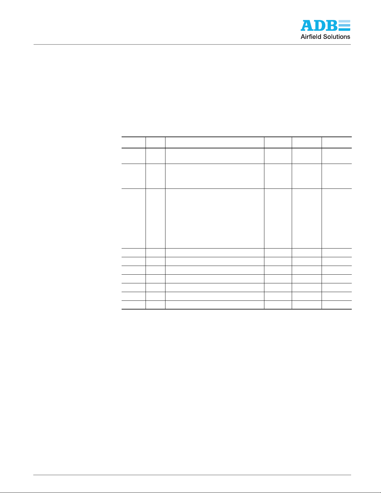
Page Rev Description Checked Approved Date
All A Released Manual
2-17
5-2
2-4, 2-5
2-8, 2-
11
2-20, 3-
3
3-5, 6-1
6-5
All D Formatting changes only JC JC 12/1/09
All E Updated entire manual RH CS 8/2/11
All F Updated format and graphics RW SM 7/18/16
Updated Figure 2-8, revised ordering
code
B
Fig 5-1
Updated Figures, specifications and
C
added enhanced features
BB/WT/R
S
JR JR 3/20/07
LD GM 4/22/09
WT 2/2/07
© ADB Airfield Solutions All Rights Reserved 5
Advanced Control Equipment (ACE2)
1
2
3
96A0357 Rev. F
Introduction
2.2 Introduction This section describes the L-827/ L-829 Advanced Control Equipment (ACE2
NOTE: ACE and ACE2 are trademarks of ADB Airfield Solutions.
The ACE2 operates either as the remote interface between the L-890 ALCMS and any
controlled element in the airfield lighting vault or as the stand-alone regulator/monitor
performing all L-827/L-829 functions in accordance with FAA AC 150 /5345-10F. The ACE2
is a universal device that can be used to control any type of CCR and/or controlled element
regardless of the manufacturer.
L-827/L-829 ACE2
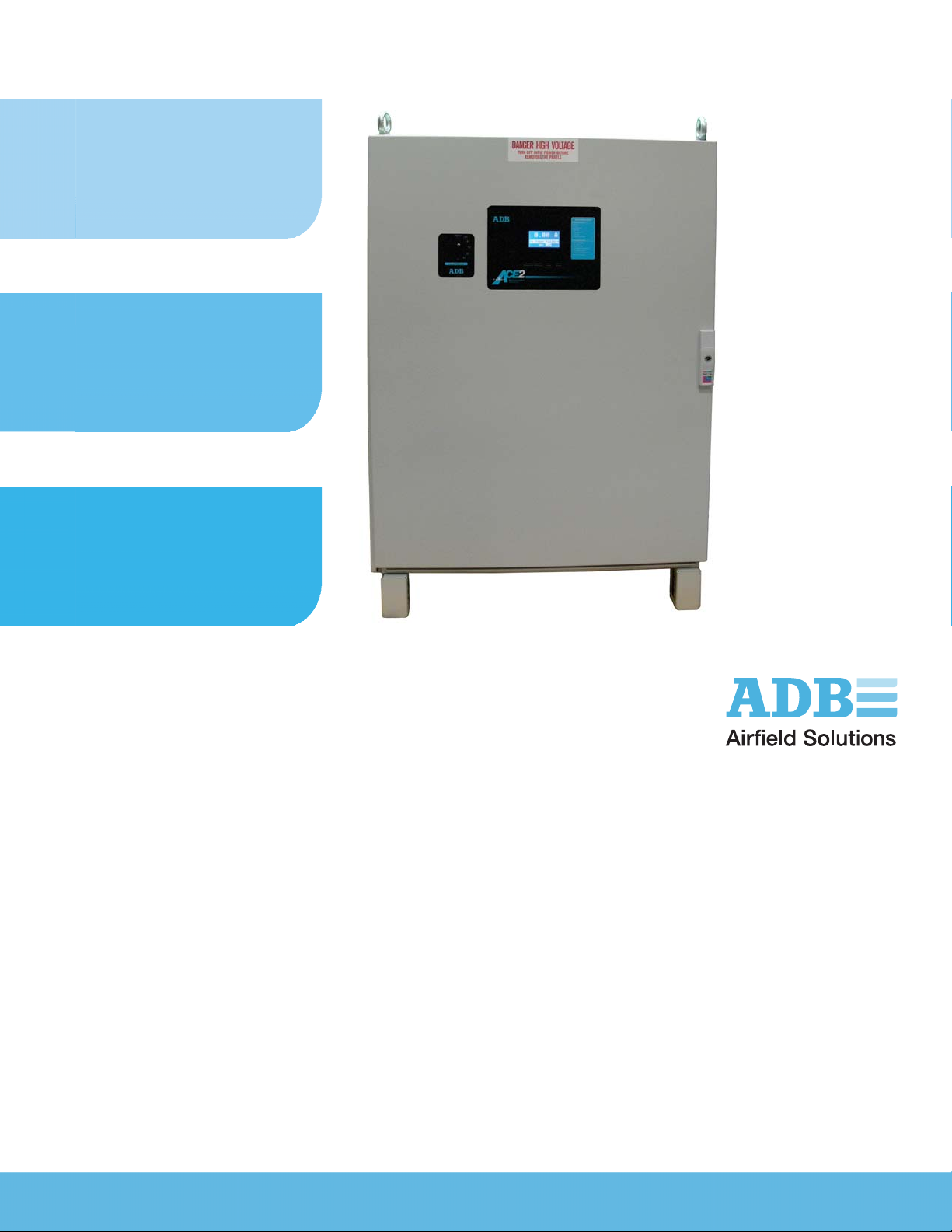
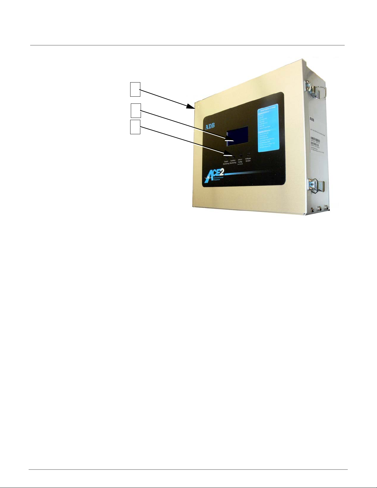
The ACE2 can be physically packaged as a Combo Box-Mount (Figure 3), a Wall-Mount
(Figure 1), or a CCR Internal-Mount (Figure 2).
version, which houses the ACE2 controller board, the IRMS board, and the CVM.
Remote-Mount is typically placed on top of the CCR. The Wall-Mount is usually bolted to a
wall or can be mounted on the front of a CCR. The internal-mount is mounted inside a ADB
Airfield Solutions L-828 CCR.
This combination is called an L-829 CCR.
ACE2:
1. Input Voltage Requirements 85 to 256 VAC, 50/60 Hz
2. Input Power Requirements12VA
3. Environmental Operating -10°C to +55°C (+14°F to +131°F)
4. Altitude Sea Level to 10,000 feet (Sea Level to 3 km)
2.2.1 Dimensions 1. Wall-Mount: 13.2 x 11.3 x 4.2 inches (33.5 x 28.7 x 10.7 cm)
2. Internal-Mount: 13.2 x 10.3 x 2.7 inches (33.5 x 26.2 x 6.9 cm)
3. Combo Box: 20.0 X 20.0 X 8.7 inches (50.8 x 50.8 x 22.1 cm)
4. Remote-Mount: 13.3 x 10.4 x 3.9 inches (33.8 x 26.4 x 9.9 cm)
The Combo Box Assembly is a wall-mount
Specifications for
TM
).
The
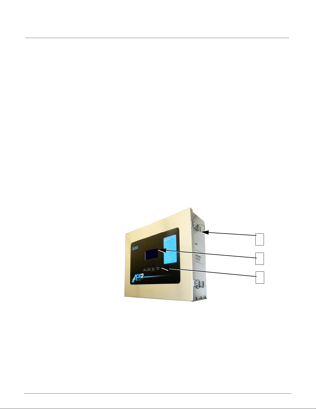
2.2.2 Wall Mount Figure 1: ACE2 Wall-Mount Assembly
1. Enclosure
2. ACE2 Front Display
3. ACE Control Keys
© ADB Airfield Solutions All Rights Reserved6

2.2.3 Internal-Mount Figure 2: Internal-Mount Assembly
1
2
3
4
1. Constant Current Regulator
2. ACE2 Display
3. ACE2 Control Keys
4. Rotary Step Switch
Refer to Figure 2. The ACE2 is a universal device that is used to control most types of CCRs
and/or controlled elements regardless of the manufacturer. The ACE2 printed circuit boards
are mounted inside a small and rugged environmental enclosure that can be:wall-mounted,
placed on a CCR, or enclosed in the CCR itself. The ACE2 consists of microprocessorbased module(s) that process communication, control commands, input/ output interface,
and failsafe functionality for controlled elements in the airfield lighting vault.
© ADB Airfield Solutions All Rights Reserved 7
Advanced Control Equipment (ACE2)
1
3
2
96A0357 Rev. F
Introduction
2.2.4 Combo Box-Mount Figure 3: ACE2 Combo Box-Mount Assembly
1. Enclosure
2. ACE2 Front Display
3. ACE2 Control Keys
© ADB Airfield Solutions All Rights Reserved8
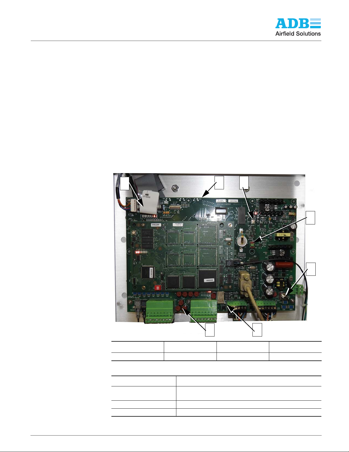
2.2.5 Main Circuit Board The Main Printed Circuit Board (Figure 4) is the central part of the design. It includes a
1
2
3
4
5
6
7
microcontroller core that implements main logic and provides calculating functions. A
communication circuit provides the interface for the redundant communication network
(RCN), which is how ACE2 receives and transmits data to the ALCMS vault computer. It
contains a fiber optic interface connection for the Current Voltage Monitor (CVM), optional
Insulation Resistance Monitoring System (IRMS), and an RS-232 local configuration
interface. The watchdog jumper (J2) is used to select whether the watchdog timer is On or
Off. Connecting pins 1 and 2 enables the watchdog timer. Connecting pins 2 and 3 disables
watchdog timer, and removing the jumper also disables watchdog timer. The normal setting
for the watchdog timer is On. The watchdog timer should only be set by qualified ADB Airfield
Solutions personnel. The reset switch (SW1) is used during the design and test phase, and
has no application for the user. The keypad switches and an LCD connector provides a
Graphic User Interface (GUI) for local control and monitoring for all controllable functions.
The display is connected to the main board by a ribbon cable. The two-position DIP switch
(SW2), is not currently used, but allows for future upgrades. The DIP switch must remain
with both selectors in the On position for proper operation. The Power Supply circuitry
provides all ACE2 equipment with a regulated and isolated power source.
The Power Supply circuitry can be turned On and Off via the main power switch in the lower
right corner of Figure 4.
Figure 4: ACE2 Main Circuit Board
1. Ribbon connector to
display board
2. Main PCB 4. SW2 6. RY7
3. SW1 5. SW7 7. Relay Fuses
Table 1: Main Board Description
Feature Function Description
Ribbon connector to
display board
Main PCB
SW1 Reset switch - Press to reset the processor
© ADB Airfield Solutions All Rights Reserved 9
 Loading...