

Page 1
Steerables
Installation Instructions
The Steerables Tilt Cable kit serves as a suspension and pul l back device f or flyable loudspeakers and can be used in a wide range of rigging applicati ons. It
provides an easy and infinit ely adjusting tilt feature for loudspeakers and other objects weighing up to 220 lbs. (134 kg). The Steerables Tilt Cable Kit comes in
standard fixed cable lengths of 8.25”, 10”, 14”, 18” and 22”. Custom l ength til t c abl e kits are also avail abl e.
The Steerables Tilt Cable Kit contains all the nec essary hardware to hang one loudspeaker in a two point or 3 point configuration. One kit includes a pair of
structural fix ed length cabl es, an adj ust abl e pull back cabl e, shackl es, clutch lock and pul l ey. A four point conf i guration requi res an extra pair of fixed cables.
Warning:
Mounting and rigging loudspeakers requi res experienced professi onals. Improperly installed loudspeakers can result in property damage, personal injury,
death and/or liabili ty to the instal li n g contracto r . Due t o the wide vari ety of buil di ng structures, materials and methods, this inst ruct i on guide as sumes that the
installing contractor will exercise proper judgment in selecting the proper rigging area, suspensi on points and equipment.
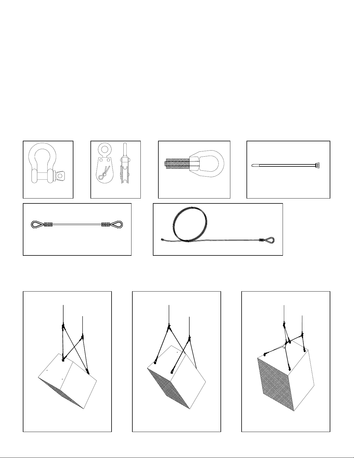
Be sure that all of the following items are includ ed in thi s kit before proceeding:
Anchor Shackle (5 pcs) Pulley Assembly (1 pc) Clutch Lock assembly (1 pc) Cable ties (5 pcs)
Tilt Cable Kit
Fixed length structural cable (2 pcs) Pull back cable (1 pc)
Before Starting:
Select the type of application from th e illu strations below then go to the corresponding page that describes that applicati on. The application will depend
on the mounting points available on the speaker.
Two Point Configuration Three Point Configuration Four Point Configuration
For Steep Angles For Medium Angles For Shallow and Medium Angles
Requires an extra pair of fixed length cables
Allen Products Co., Inc. Signal Hill, CA 90755 (562) 424-1100 0503
Page 2
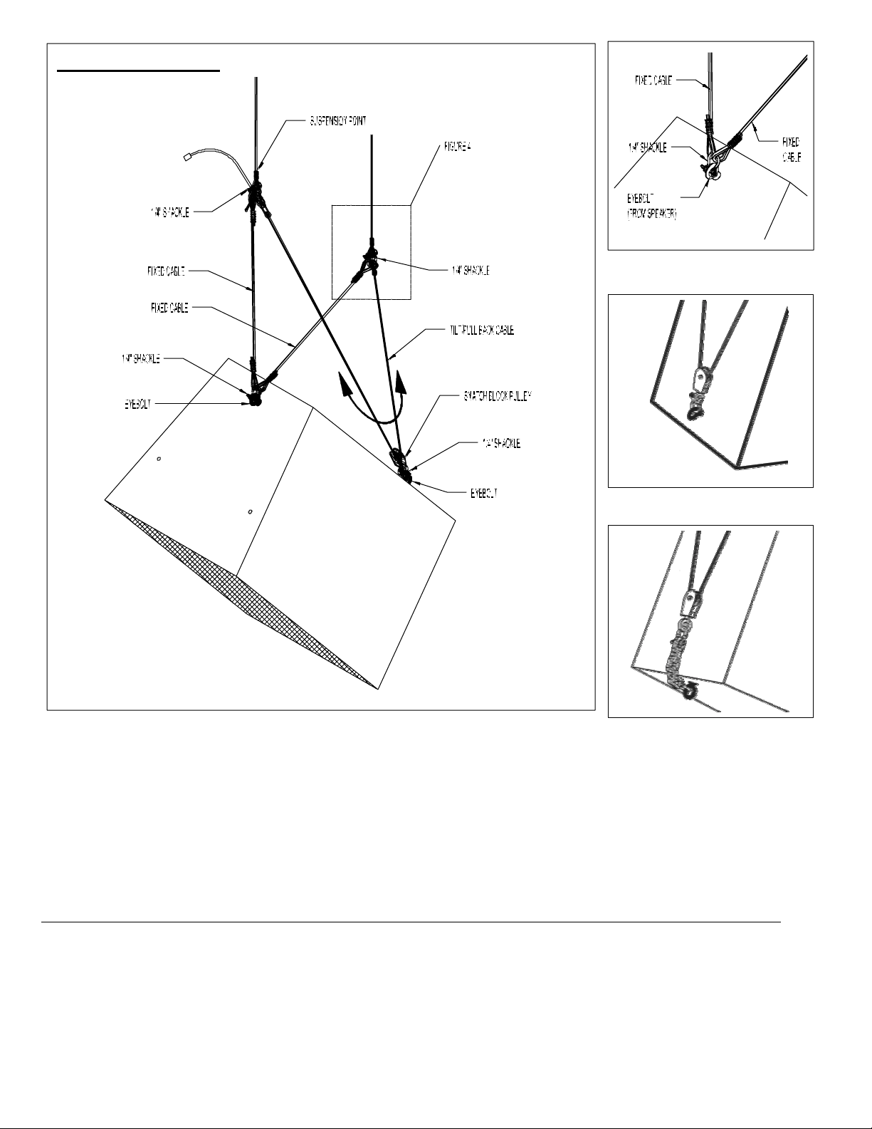
Two-Point Configuration
Figure 1: Fixed cable assembly
Figure 2: Pull back-direct
Step 1. Attach Fixed Cables
Attach one end of each fixed cable to the top anchor point of the speaker (such as eyebol t, track fitting, etc) usin g a
supplied shackle (Figure 1).
Step 2. Assemble Pull-Back Cable to Fixed Cable
Capture the eye of the clutch lock (at the end of the pull back cable) and one of the fixed cables with one of the selected suspension points using a supplied shackle.
(Figure 5) Repeat with the other fixed cable, suspension point and the other end of the pull back cable (Figure 4).
Step 3. Attach Pulley to the Pull-Back Cable
Using the pulley’s shackle, capture the eyebolt or fitting at the speaker’s pull back point (Figure 2).
Step 4. Adjust / Increase Slack of the tilt cable
Loosen the knurled end of the clutch lock. Com press the knurled end inward wh ile pulli ng the cable toward s the pulley until the desired length is achieved (Figure 6).
If there is no rigging point available at the back of the speaker, use a rigging point from the bottom of the speaker to connect a back chain extension (Figure 3).
Step 5. Adjust Speaker’s Tilt Angle
To increase the tilt angle of the speaker, compress the knurled end of the clutch lock then pull the pull back cable away from the pulley until the desired angle is achieved.
To decrease the tilt angle of the speak er, support the weight of the speaker while compres sing the knurled end of the clutch lock then slowly lower the speak er until the
desired tilt angle is achieved. Release the knurled end to lock in place then tighten (Figure 6). Coil the extra cable or trim cable and place a stop swage on the end.
Step 6. Secure Shackles and Clutch Lock
To prevent the screw pin of the shackles from loosening over time, secure them with a supplied tie wrap as shown in figure 8. Tape the knurled end of the clutch lock to
avoid long term loosening.
Figure 3: Pull- back relocated
(Requires back chain extension)
Allen Products Co., I nc. Signal Hill, CA 90755 (562) 424-1100 0503
Page 3
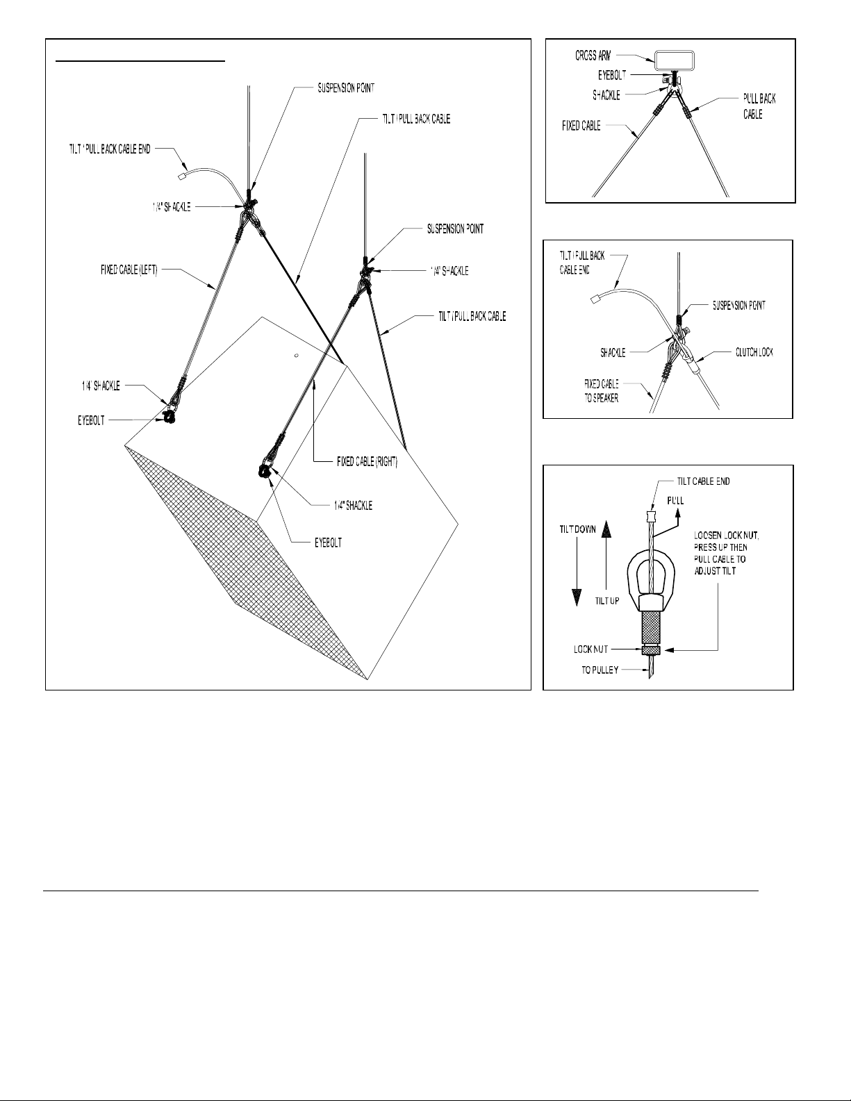
Three-Point Configuration
Step 1. Attach Fixed Cables
Attach one end of each fixed cable to the top anchor points of the speaker (such as eyebolt, track fitting, etc) using supplied shackles as shown in the above drawing.
Step 2. Assemble Pull-Back Cable to Fi xed Cable
Capture the eye of the clutch lock (at the end of the pull back cable) and one of the fixed cables wit h one of the selected suspension points using a supplied shackle.
(Figure 5) Repeat with the ot her fixed c abl e, sus pension point and the other end of the pull back cable (Figure 4).
Step 3. Attach Pulley to the Pull-Back Cable
Using the pulley’s shack l e, capture the eyebolt or fitting at the speaker’s pull back poi nt (Fi gure 2).
Step 4. Adjust / Increase Slack of the Pull -Back Cable
Loosen the knurled end of the clutch lock. Compress the knurled end i nward whi l e pulling the cable towards the pulley until the desired length is achieved (Figure 6).
If there is no rigging point availabl e at the back of the speaker, use a rigging point from the bottom of the speaker to connect a back chain extension (figure 3).
Step 5. Adjust Speaker ’ s Tilt Angl e
To increase the tilt angle of the speaker, compress the knurl ed end of t he clutc h lock then pull the pull back cabl e away f rom t he pulley unti l desired angle is achieved. To
decrease the tilt angle of the speaker, s upport the weight of the speaker while compressing the knurled end of the cl utc h lock then slowly l ower the speaker until the
desired tilt angle is achi eved. Releas e the knurled end to lock in place then tighten (Figure 6). Coil the extra cable or trim and place a stop swage on the end.
Step 6. Secure Shackl es an d Clutch Lock
To prevent the screw pin of the shackles from loosening over time, secure them with a supplied tie wrap as shown in figure 8. Tape the knurled end of the clutch lock to
avoid long term loosening.
Figure 4: With Cross Arm suspension point
Figure 5: Clutch lock and fixed cable assembly
Figure 6: Clutch lock tilting mechanism
Allen Products Co., Inc. Signal Hill, CA 90755 (562) 424-1100 0503
Page 4
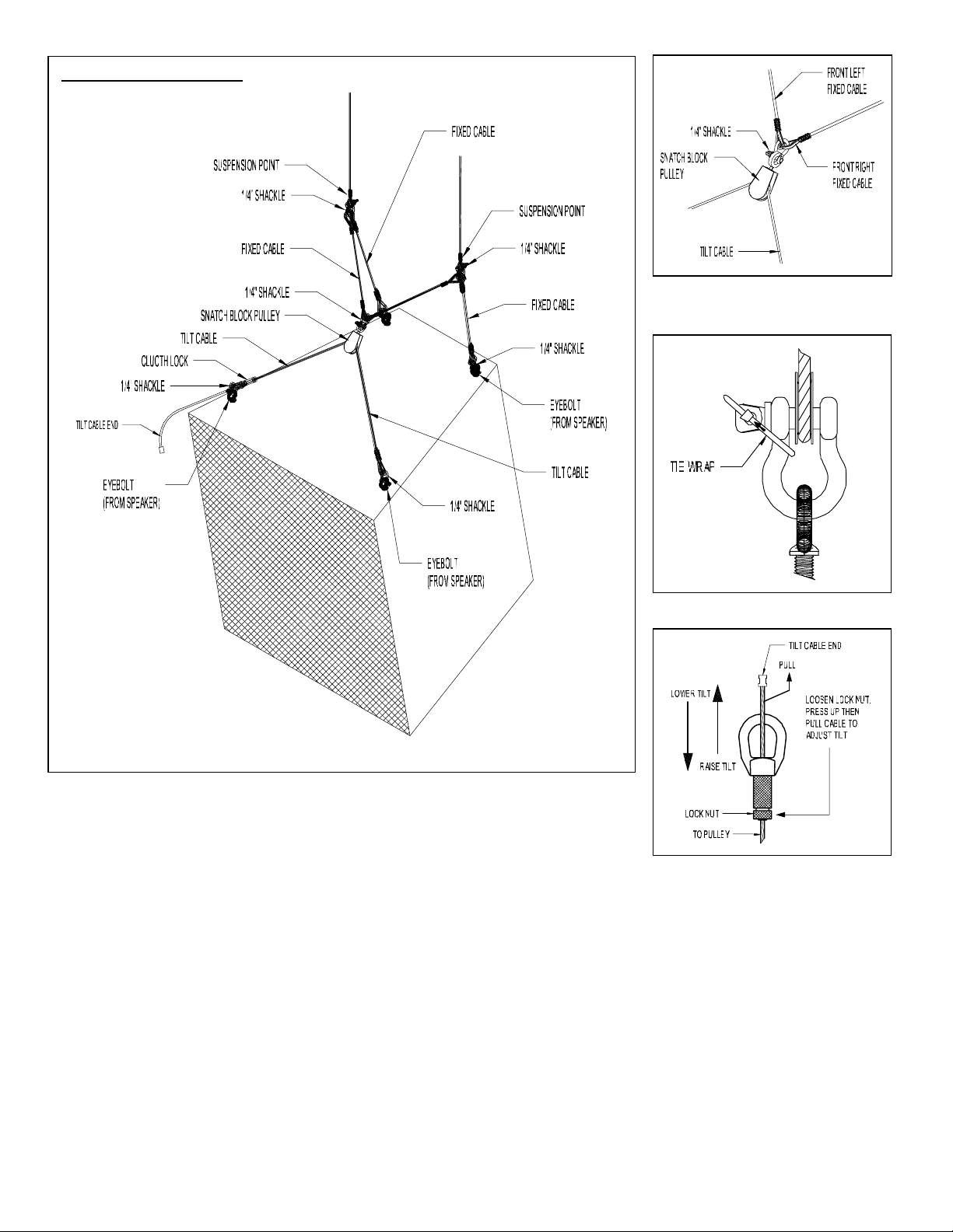
Four-Point Configuration
Figure 7: Pulley and Fixed Cable assembly
Figure 8: Securing the shackles
Step 1. Attach Tilt / Pull-Back Cable
Connect the pullback cable to t he top front anchor points of t he speaker (such as ey ebolts or track fittings, etc) as
shown in the above drawing. Usi ng the pull ey’s shack l e, s ecure one end of both fixed cables to t he pulley (Fi gure 7).
Step 2. Attach Rear Fixed Cables
Attach each end of the second set of fixed cables to the back anchor points of the speaker with the supplied
shackles as shown in the above drawing.
Step 3. Attach Fixed Cable to Main Suspension Point
Connect the front left and the rear left fixed cables to the left suspension point (of your chosen rigging or mounting equipment) using the supplied shackle (Figure 4).
Repeat step for the right front and right rear fixed cables.
Step 4. Adjust Speaker’ s Tilt Angl e
To decrease the tilt angle of the speaker, compress the knurled end of t he clutc h l ock t hen pull the pull back cabl e away from the pulley until the desired angle is
achieved. (Figure 9) To increase the tilt angle of the speaker, support the weight of the speaker then compress the knurl ed end of the clutc h l ock and slowly l ower the
speaker until the desired angle is ac hi eved. Release the knurled end to lock in place then tighten (Figure 9). Coil the extra cabl e or trim and place a stop swage on the
end.
Step 5. Secure Shackles and Clutch Lock
To prevent the screw pin of the shackles from loosening over t i m e, sec ure them usin g a tie wrap as shown in figure 8. Tape the knurled end of the clutch lock to avoid
long term loosening.
Figure 9: Clutch Lock tilti n g mechanism
Allen Products Co., Inc. Signal Hill, CA 90755 (562) 424-1100 0503
 Loading...