

Page 1
SBC3-8-CA-20
Installation Instructions for Swivel Beam Clamp
The SBC3-8-CA-20 is a load rated overhead swivel beam clamp with
a 20” cross arm for mounting and suspending speakers. It is used to
mount speakers with the AJ-1524 adjustable U-Bracket, stand yoke
mounts or as a suspension arm when eyebolts are installed. The
cross arm provides a rotation of 360° horizontally.
Warning:
Mounting and rigging audio equipment requires experienced
professionals.
equipment can result in property damage, personal injury,
death and/or liability to the installing contractor.
Important:
Due to the wide variety of overhead structures, rigging materials
and rigging methods, these instructions assume that the installing
contractor/installer will exercise good judgment in selecting the
proper suspension points, hardware and mounting area.
As a guide, the installation, when completed should be
capable of supporting at least 5 times the actual applied
Do not exceed the rigging system’s working
load.
load limit of 300 Lbs. Use only Grade 8 hardware or
load rated hardware to ensure a safe installation.
Package Contents:
1 pc. SBC3-8-CA-20 Beam Clamp w/ 20” Swivel Arm
1 kit Hardware kit
1 pc. Instruction sheet
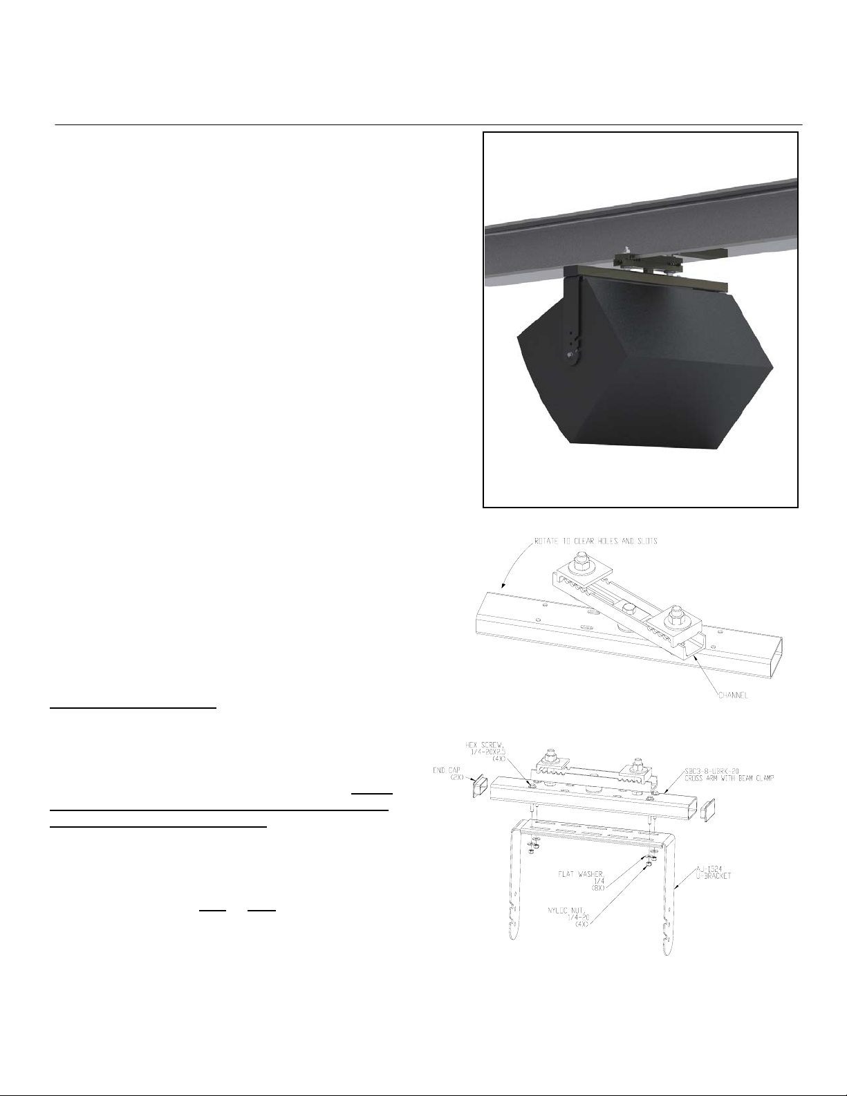
Step 1.
Rotate the cross arm to the desire angle to have access to the
slot of the cross arm (Figure 1, 2).
For mounting Speakers:
Step 2.
Attach the AJ-1524 adjustable u-bracket to the cross
arm using the two ¼-20X1 hex screws, nuts and
washer on the four outer holes of the cross arm. On the
15” wide or near 15” speaker use only the four through
holes on the cross arm (Figure 2). Make sure to place
the spacer clip in between the inner bracket and the
cross arm. Do not permanently tighten. Adjust the AJ1524 to the size of the speaker, add at least ½” gap for
the gaskets. Capture the overlap of the AJ-1524 inner
and outer bracket using two
bolts, nuts and washers on the slots of the cross arm
(Figure 3). Tighten all bolts permanently.
Improperly installed audio and video
or four ¼-20X2.5 hex
Swivel Beam Clamp
Figure 1
Figure 2
© 2010 ATM Fly-Ware Signal Hill, CA 90755 (562) 424-1100 06/07/10
Page 2
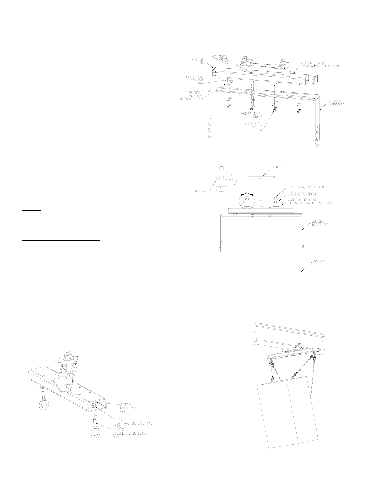
Step 3.
Attached the swivel beam assembly to the
attachment I-beam. Adjust the Locking plate so that
the bolts of the locking plates are a close or
touching to the sides of the I-beam. Make sure that
the locking plate is also secure and resting on the
grooves of the channel. Make sure the beam clamps
channel is centered to the attachment I-beam.
Clamp the locking plates tightly to the beam both
vertically and horizontally with the 5/8” bolts,
washers and nuts. Add loctite thread compound to
the threads of the bolts over the nut (Figure 4).
Step 4.
Put on the two end caps for the cross arm (Figure
2, 3).
Step 5.
Attach the speaker to the AJ-1524 adjustable ubracket with the hardware kit that comes with it.
Adjust the tilt angle and tighten the screws on the
sides. Refer to AJ-1524 product instruction
sheet.
For suspending speakers:
Step 1.
To Suspend a speaker to the cross arm, install the
eyebolts to the center holes of the cross arm close to
the edge. Use load rated hardware to suspend the
speaker (Figure 5 and 6).
Figure 3
Step 2.
Figure 4
Install the hole plug to the center hole on the bottom of the tube.
Step 3.
Repeat step 3 and 4 to attach the Swivel beam clamp to the I-Beam.
Figure 5
Figure 6
© 2010 ATM Fly-Ware Signal Hill, CA 90755 (562) 424-1100 06/07/10
 Loading...