

Page 1
SAS-1WA-20 One-Way-Array
Installation Instructions
The One Way Array is a load rated overhead
suspension product used to suspend and aim a single
loudspeaker cabinet and other objects equipped with
safe rigging points.
Warning:
Mounting and rigging audio equipment requires
experienced professionals.
audio and video equipment can result in
property damage, personal injury, death
and/or liability to the installing contractor.
Important:
Due to the wide variety of overhead structures,
rigging materials and rigging methods, these
instructions assume that the installing
contractor/installer will exercise good judgment in
selecting the proper suspension points, hardware and
mounting area.
As a guide, the installation, when completed should be capable of supporting at least 5 times the actual
applied load.
Do not exceed the rigging system’s working load limit. Use only Grade 8 hardware at
attachment points to ensure a safe installation.
Package Contents:
1 pc. One Way Array 4 pc. 1/4-20 x 3/4” pan screw
4 pc. 5/16” Eye bolts 4 pc. 1/4-20 nylock nut
4 pc. 5/16-18 nylock nut 8 pc. ¼” flat washer
8 pc. 5/16” flat washer 4 pc. End cap 1 pc. Cotter pin
For Rigging Installation:
Direct suspension of hardware (cable or chain) to the building’s suspension points should provide an approximate 5°
splay angle off (vertical) axis each, to achieve the proper tension. Be sure that the combined overhead suspension points
are capable of supporting at least 5 times the weight of the entire suspended load.
Step 1.
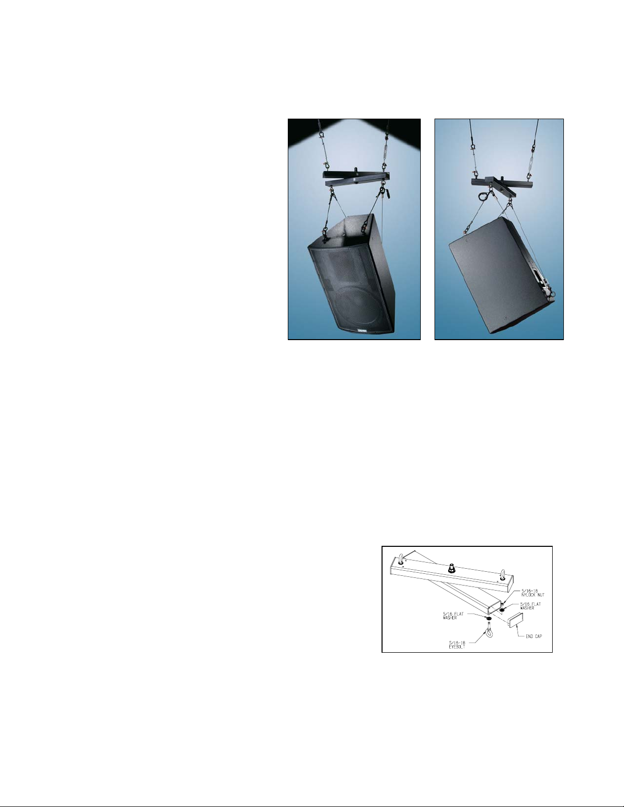
Install the 5/16” eyebolts to the upper arm of the One-Way Array, as
illustrated in fig. 1 with the provided washers and nuts.
Step 2.
Repeat steps for the lower arm. Do not tighten permanently yet.
Step 3.
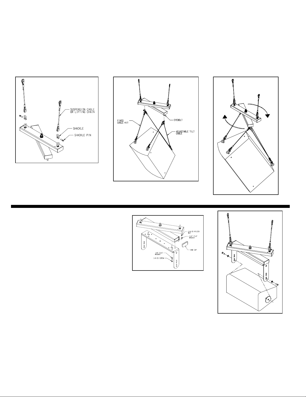
Attach the selected suspension hardware (cable or chain) to the eyebolts
of the upper arm of the One-Way Array (figure 3).
Step 4.
Suspend the loudspeaker from the selected tilting device such as the
Steerables cable tilting system. If fabricating your own, use load rated rigging hardware. Attach load rated rigging
hardware to the lower Cross Arm’s eyebolts (Figure 3). See Adjustable Tilt Cable kit Instruction sheet for
installation.
Improperly installed
Figure 1
© 2003 Allen Products Co., Inc. Signal Hill, CA 90755 (562) 424-1100 0704
Page 2
Step 5.
Orient the Cross Arm eyebolts so that all binding is removed under load Condition. Tighten nuts on eyebolts for both
upper and lower cross arms. Press fit tube end caps over tube ends.
Step 6.
Adjust the speakers horizontal angle by rotating the lower cross arm until the desired horizontal angle is achieved (Figure
4).
Before hoisting, lift the entire system a short distance and check each and every connection thoroughly before
proceeding.
Figure 2:
Figure 3: Adjustable Tilt Cable Kit
Figure 4
For U-Bracket Installation:
Step 1.
Remove the center bolt from One-Way Array
assembly leaving the center friction washer in
place.
Step 2.
Line up the center holes of the U-bracket and the
center hole of the lower cross arm. Reinsert the
bolt with the washers through it. Do not fully
tighten center bolt yet.
Figure 5
Step 3.
Permanently secure the selected U-bracket to the lower cross arm’s four holes using ¼20 hardware provided with the one-way array kit. (new holes may have to be drilled in
U-bracket) Tighten center bolt to 20 lbs torque with a torque wrench. (figure 5)
Step 4.
Press fit the end caps to the ends of the Cross Arm tube as shown.
Figure 6
Step 5.
Attach speaker to the U- bracket with hardware provided (see U-bracket instructions). Adjust tilt angle of speaker to
desired angle then tighten side bolts permanently. Refer to Step 4 of Rigging Installation for attachment to
structure
Step 6.
Adjust horizontal pan angle of speaker then tighten permanently.
© 2003 Allen Products Co., Inc. Signal Hill, CA 90755 (562) 424-1100 0704
 Loading...