

Page 1
Rev01. 112105
SAS-100-WM Wall Mounting Arm
Adjustable Tilt Cable Application
Installation Instructions
Thank you for selecting the SAS-100-WM speaker wall mount. This universal
speaker wall mount is designed to allow the rigging and aiming of speakers, that
have mounting points to walls or other safe vertical structures.
Important:
Mounting and rigging video equipment requires experienced professionals.
Improperly installed video equipment can result in property damage,
personal injury, death and/or liability to the installing contractor. Do not
install if in doubt about the integrity of the mounting structure.
Follow these instructions for the most efficient and safest mounting
results.
Caution:
Due to the wide variety of wall structures, materials and mounting methods, these
instructions assume that the installing contractor will exercise good judgment in
selecting the proper mounting area and hardware.
As a guide, the installation, when completed should be capable of supporting at
least 5 times the actual applied load.
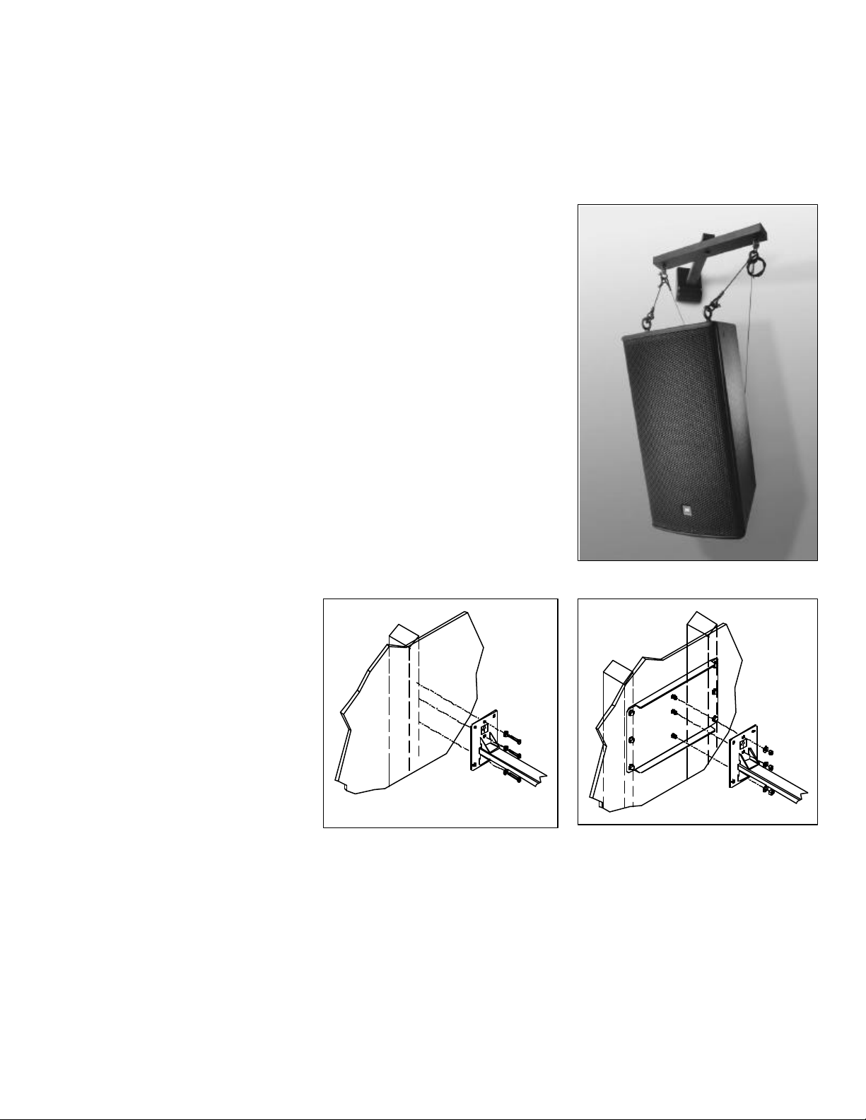
Step 1. Attach mounting arm to wall:
Secure the mounting arm assembly to the
wall with the “This End Up” label arrow
pointing up. An optional Stud Brace Plate
is available to adapt to structural wall
studs. Model#:
WP-16 and WP-24. Check with your
hardware specialist for proper mounting
hardware (Figure 1).
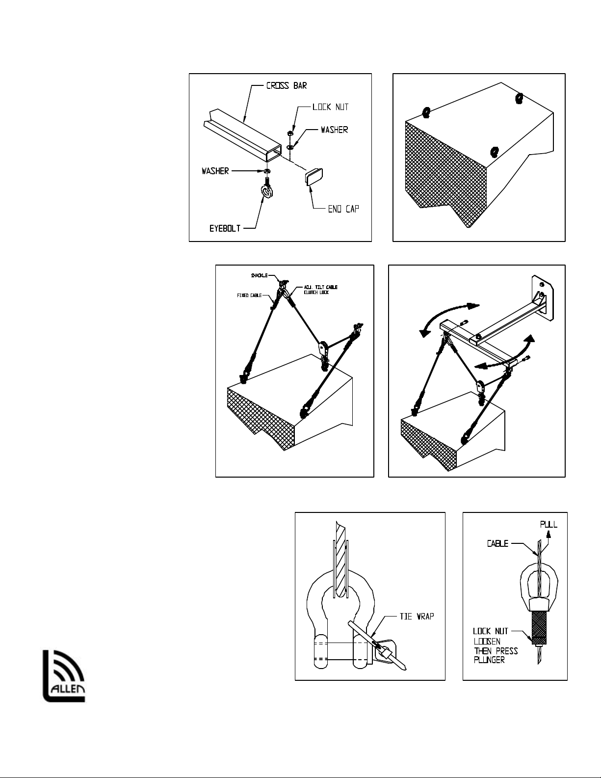
Step 2. Secure Eyebolts:
Attach eyebolts to cross bar then the end
cap (Figure 2A).
Attach eyebolts or required rigging
attachments to the speaker cabinet
(Figure 2B)
Step 3. Install Fixed Cables to the
Speaker Cabinet:
Select the fixed cables from the cable kit. Attach one (1) fixed cable to each front attach point of the speaker using the 5/16”
shackles. Secure the screw pin to the shackle using the included cable tie (Figure 3).
Step 5. Install Tilt Cable to Speaker Cabinet:
Capture the eye of the pulley of the adjustable tilt cable kit to the back attach point of the speaker using the 5/16” shackle.
Secure the pin to the shackle using the included cable tie (figure 3).
2001 Allen Products Company Incorporated, Signal Hill, CA 90806 USA (562) 424-1100
Figure 1 Optional Accessory: Stud Brace Plate
Page 2
Rev01. 112105
A
Step 6. Hang Speaker from
Cross Arm:
Attach the eye of the clutch lock
of the pulley cable to the loop of
one fixed cable and one eyebolt
from the SAS-100-WM wall
mount with a 5/16” shackle.
Attach the other end of the pulley
cable to the other fixed cable and
SAS -100-WM wall mount eyebolt
with a 5/16” shackle (Figure 4).
Secure shackle pins with the
included tie wraps (Figure 5).
Step 9. Adjust Pan Angle:
Hold both ends of the cross bar
then slightly twist horizontally
(clockwise or counter clockwise)
until desired direction is achieved
(Figure 4).
Step 10. Adjust Tilt Angle:
Loosen the lock nut on the clutch lock
halfway then pull the free end of the
adjustable tilt cable up until desired tilt
angle is achieved. Tighten lock nut to
secure tilt angle. To release tilt angle,
loosen the locknut halfway and depress
plunger while supporting the weight of
the speaker (Figure 6).
Figure 2A Figure 2B
Figure 2B
Figure 3 Figure 4
llen Products Company Inc.
1635 E. Burnett Street
Signal Hill, CA 90755 USA
Tel: (562) 424-1100 Fax: (562) 4243520
2001 Allen Products Company Incorporated, Signal Hill, CA 90806 USA (562) 424-1100
Figure 5 Figure 6
 Loading...