

Page 1
SAS-100-CM Ceiling Mount
Adjustable Tilt Cable Application
Installation Instructions
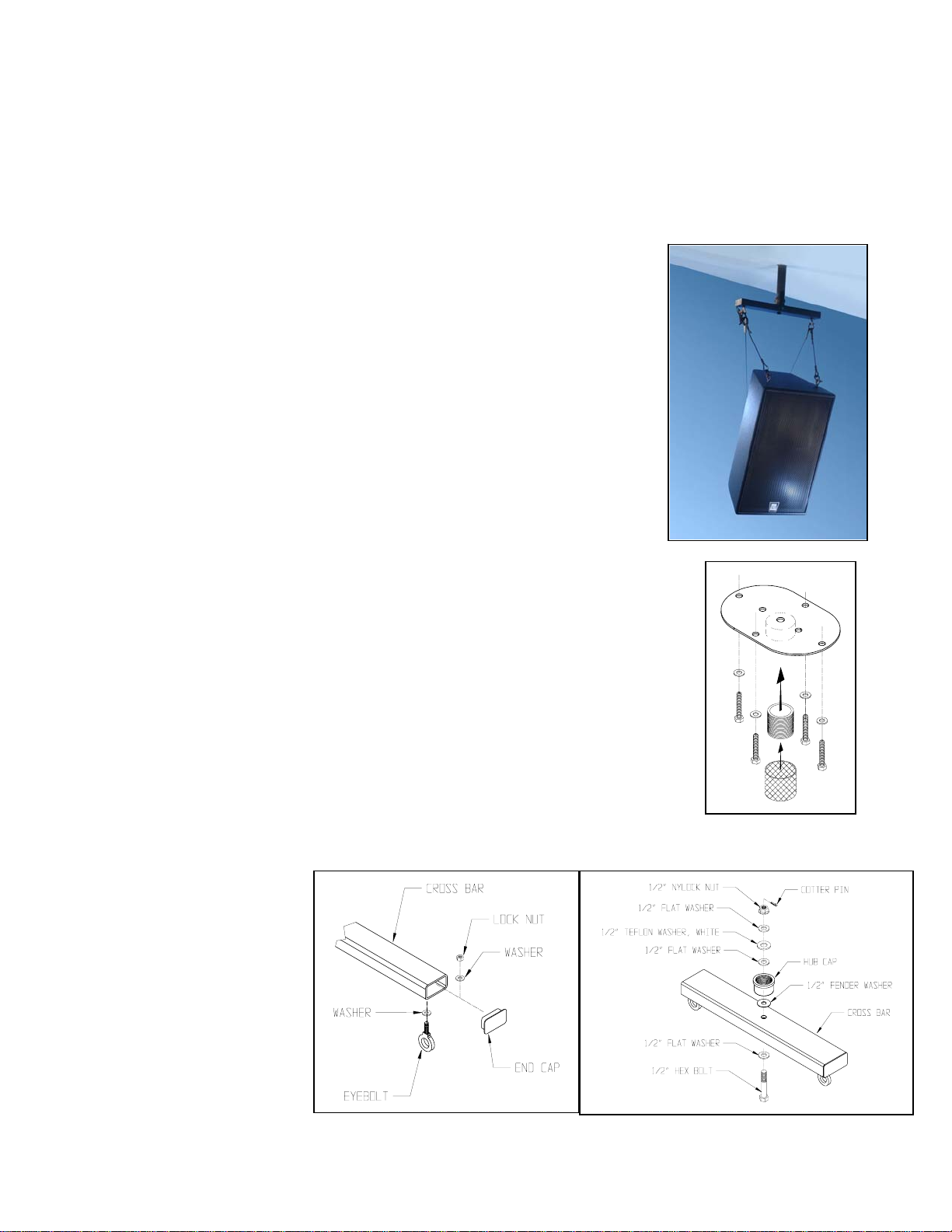
Thank you for selecting the SAS-100-CM Steerable Speaker Ceiling Mount. This
universal ceiling speaker mount provides a 360° pan angle adjustment. It suspends
and precisely aims speakers equipped with rigging points from ceilings and other
structural overhead surfaces.
Important:
Mounting and rigging video equipment requires experienced professionals.
Improperly installed video equipment can result in property damage,
personal injury, death and/or liability to the installing contractor.
install if in doubt about the integrity of the mounting structure.
Caution:
Due to the wide variety of building structures, materials and mounting methods, these
instructions assume that the installing the contractor/installer will exercise good
judgment in selecting proper mounting area and hardware.
As a guide, the installation, when completed should be capable of supporting at least 5
times the actual applied load.
Follow these instructions for the most efficient and safest mounting results.
Step 1. Install Ceiling Plate:
Secure the ceiling plate above a structurally sound horizontal grid. Be sure the ceiling plate
center is level and directly above your desired suspension point (Figure 1).
doubts about the integrity of the structure you are mounting to, or you are not sure about
the proper hardware to use, consult your local hardware specialist.
Step 2. Install Extension Coupler:
Thread the extension coupling into the threaded hub of the ceiling plate, then place the
wire mesh cover around it(Figure 1).
Step 3. Assemble the Cross Arm:
Permanently attach the eyebolts to the cross bar with flat washers and Nylock nuts then the end
caps (Figure 2).
Step 4. Assemble the Center
Hub:
Assemble the hub to the cross arm
using the hex bolt, washers, Teflon
washer and Nylock nut. Insert the
cotter pin into the hole of the 1/2”
bolt then fold the end to secure
(Figure 3).
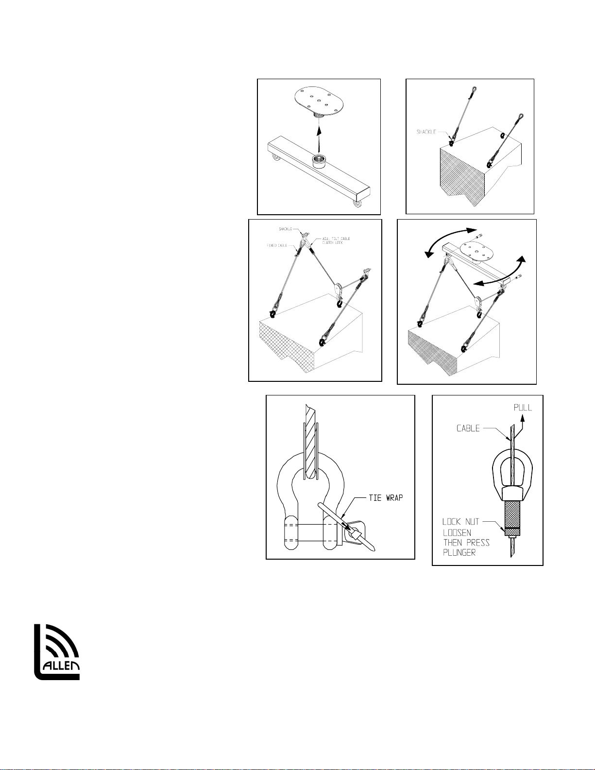
Step 5. Install Cross Arm to
Ceiling Plate:
Align and hand thread the hubcap
of the cross arm assembly over the
extension coupling inside the ceiling plate. Use a pipe wrench to tighten connection permanently (Figure 4). Slip mesh
evenly over both hubs.
© 2004 Allen Products Company Incorporated, Signal Hill, CA 90755 USA (562) 424-1100 07/04
Figure 2
Do not
If you have
Figure 3
Figure 1
Page 2
A
Step 6. Prepare Loudspeaker:
Attach eyebolts, fly track or required other
attachments to the speaker cabinet (Figure 5). If
using the optional Adjustable Tilt Cable Kit,
see
Adjustable Tilt Cable Kit data sheet for kit
selection, methods of attachment and aiming.
Step 7. Install Selected Fixed Cables:
Identify the fixed cables from the selected
Adjustable Tilt Cable Kit (Ordered separately).
Attach one (1) fixed cable to each front
attachment point of the speaker using the 5/16”
shackles (Figure 5). Secure the screw pin to the
shackle using the included cable tie to prevent
the pin from rotating out (Figure 8).
Step 8. Install Adjustable Tilt Cable:
Capture the eye of the pulley of the adjustable
tilt cable kit to the back attachment point of
the speaker using the 1/4” shackle (Figure 6).
Secure the pin to the shackle using the
included cable tie to prevent the pin from
rotating out (Figure 8).
Step 9. Suspend the Speaker from the
Cross Arm:
Using a 5/6” shackle, attach the clutch lock eye
of the adjustable cable and one fixed cable to
one eyebolt of the cross arm. Attach the other end
of the adjustable cable and the other fixed cable to
the other cross arm eyebolt with a 5/16” shackle
(Figure 6). Fully tighten shackle pins and secure
with the included tie wraps (Figure 8).
Figure 4
Figure 5
Figure 7
Figure 6
Figure 9
Figure 8
Step 10. Adjust the Pan Angle:
Hold both ends of the cross bar then slightly turn
horizontally (clockwise or counter clockwise) until
desired direction is achieved (Figure 7).
Step 11. Adjust the Tilt Angle:
Loosen the lock nut on the clutch lock halfway then
pull the free end of the adjustable tilt cable up
while supporting the weight of the speaker until
desired tilt angle is achieved. Tighten lock nut to secure tilt angle. To release tilt angle, loosen the locknut halfway and
depress plunger while supporting the weight of the speaker until desired tilt angle is achieved then release the plunger
(Figure 9).
Figure 2
llen Products Company Inc.
1635 E. Burnett Street
Signal Hill, CA 90755 USA
Tel: (562) 424-1100 Fax: (562) 424-3520
Web Site: www.allenproducts.com
© 2004 Allen Products Company Incorporated, Signal Hill, CA 90755 USA (562) 424-1100 07/04
Page 3

SAS-100-CM Ceiling Mount
U-Bracket Application
Installation Instructions
Thank you for selecting the Steerable SAS-100-CM Ceiling Mount. This
universal ceiling speaker mount provides a 360° pan angle adjustment.
It suspends and precisely aims speakers equipped with rigging and
mounting points from ceilings and other structural overhead surfaces.
Important:
Mounting and rigging video equipment requires experienced
professionals.
in property damage, personal injury, death and/or liability to
the installing contractor.
of the mounting structure.
Caution:
Due to the wide variety of building structures, materials and mounting methods, these
instructions assume that the installing contractor/installer will exercise good judgment in
selecting the proper mounting area hardware.
As a guide, the installation, when completed should be capable of supporting at least 5 times
the actual applied load.
Follow these instructions for the most efficient and safest mounting results.
Step 1. Install Ceiling Plate:
Secure the ceiling mount above a structurally sound horizontal grid. Be sure the ceiling plate
center is level and directly above your desired suspension point (Figure 1).
about the integrity of the structure you are mounting to, or you are not sure about the proper
hardware to use, consult your local hardware specialist.
Step 2. Install Extension coupler:
Thread the extension coupling into the threaded hub of the ceiling plate then place the wire
mesh cover around it (Figure 1).
Step 3. Attach Selected U-Bracket to Cross Arm:
Attach the selected U-Bracket to the cross arm using four 1/4-20 screws, 1/4” flat washers
and locknuts. Do not tighten. Make sure the 1/2” diameter center hole of the U-Bracket
clears the center hole of the cross arm (figure 2).
Step 4. Assemble Hubcap to Cross Arm:
Attach the hubcap to the cross bar/U-bracket assembly, first with the 1/2 hex bolt from
under the U-Bracket then the washers and nut (Figure 3). Tighten permanently but do not
over tighten. Insert cotter pin into the hole of the 1/2” bolt then secure the ends around
the bolt. Tighten the U-bracket’s 1/4-20 screws permanently (Figure 3).
Step 5. Join Cross Arm to Ceiling Plate:
Align and hand thread the hubcap of the cross arm assembly over the extension coupling
inside the ceiling plate. Use a pipe wrench to tighten connection permanently (Figure 4).
Slip mesh over hub.
Step 6. Attach Speaker:
Attach Speaker to selected U-Bracket
© 2004 Allen Products Company Incorporated, Signal Hill, CA 90755 USA (562) 424-1100 07/04
Improperly installed video equipment can result
Do not install if in doubt about the integrity
(See U-bracket Instruction sheet for speaker installation).
If you have doubts
Figure 1
Figure 2
Page 4

A
Step 7. Adjust the Pan Angle:
Hold both ends of the cross bar then slightly turn horizontally (clockwise or counter clockwise) until desired direction is
achieved (Figure 5).
Step 8. Adjust the Tilt Angle:
See U-bracket Instruction sheet.
Figure 3 Figure 4
Figure 5
llen Products Company Inc.
1635 E. Burnett Street
Signal Hill, CA 90806 USA
Tel: (562) 424-1100 Fax: (562) 424-3520
Web Site: www.allenproducts.com
© 2004 Allen Products Company Incorporated, Signal Hill, CA 90755 USA (562) 424-1100 07/04
 Loading...