

Page 1

PoleStar™ Pole Mount Support Arm
Installation Instructions for PM-SA-12, 18 and 24
Thank you for choosing the PoleStar™ Support Arm. This all-weather,
stainless steel support arm is designed to mount loudspeakers from
vertical surfaces and columns. The PoleStar™ Support Arm
accommodates many standard mounts for a wide variety of mounting
solutions, including, the PoleStar™ Pole Adapter, yokes and U-Brackets
and the PoleStar™ Dual adapter for mounting and aiming two
loudspeakers.
Important: Mounting overhead system requires professional
experience. Improperly installed equipment can result in property
damage, personal injury, death and/or liability to the installing
contractor. Do not install if in doubt about the integrity of the mounting
structure.
Caution: Due to the wide variety of mounting structures, environments,
materials and mounting methods, these instructions assume that the installing
contractor will exercise good judgment in selecting the proper mounting area
and hardware.
Follow these instructions for the most efficient and safest mounting
results.
Do not exceed the working load limit of 300lbs/136 kg.
DO NOT use Pneumatic tool to tighten bolts.
Use lubricants to bolts and nuts to prevent thread galling and seizing
before assembly.
Bolt Torque: 35 foot pounds
Package Contents:
1 pc. PoleStar Support Arm 2 pcs. Square Plastic End Caps
4 pcs. Round Plastic End Caps 1 pc ½-13 x1.5 tap bolt
1 pc ½-13 nylock nut 2 pcs ½ split lock washer
1 pc Friction gasket 1 pc Instruction sheet
1 pc Anti-seize lubricant
Step 1. Mounting the Support Arm to a flat vertical structure
Attach the Support Arm to the selected mounting area using fasteners
and/or methods suitable for the mounting structure material. If in
doubt, consult a local hardware specialist. (Fig. 1)
Step 2. Mounting the Support Arm to a Pole Adapter:
Secure the PoleStar Support Arm to the selected Pole Adapter (PMMOUNT-6UP or PM-MOUNT-6DOWN) using the Adapter’s included ½
bolts, flat washers and nylock nuts (Fig. 2). Tighten bolts permanently.
Fig. 1
Fig. 2
© 2008 Allen Products Company, Signal Hill, CA 90755 USA (562) 424-1100 REV02-042710
Page 2
Step 3. Strapping the Support Arm and Adapter to a pole
Decide the final horizontal pan angle of the support arm then, using the instructions from the selected PoleStar Band Kit,
secure the Support Arm to the column permanently (See Band Kit Instruction sheet).
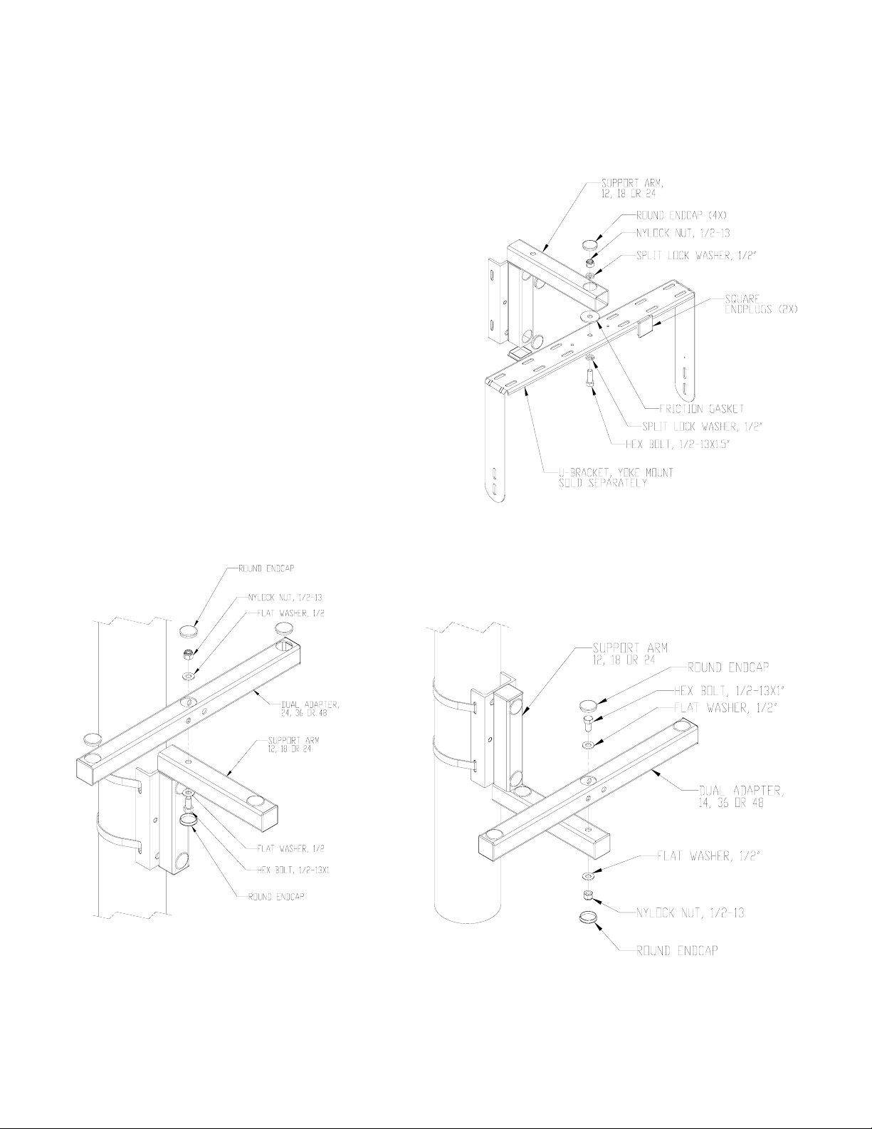
Step 4 Attaching a Mount to the Support Arm.
Attach the selected mount’s center hole to the Support Arm’s
end hole using the included ½-13 x 1.5” hex bolt, split lock
washer and nylock nut. Make sure the friction washer is
placed in between the support arm and the yoke. Allen/ATM UBrackets and Dual Adapters Kits shown in Fig. 3, 4 and 5.
Step 5. Install and Aim Speaker(s)
Following the instructions of the mount, install and aim
loudspeaker then tighten hardware and angles permanently.
Step 6. Install End Caps and plugs:
After installation, cover the end of the pole arm with the 2 x 2
end caps and the round holes with the round hole plugs. Trim
end caps if necessary to clear bolts head and washers (Fig.3).
Step 7. Install Safety Cable
Secure a safety cable to the pole or column, and then attach
the other end of the safety cable to the speaker to bypass the
mounting system.
Fig. 3
Fig. 4
Fig. 5
© 2008 Allen Products Company, Signal Hill, CA 90755 USA (562) 424-1100 REV02-042710
 Loading...