

Page 1
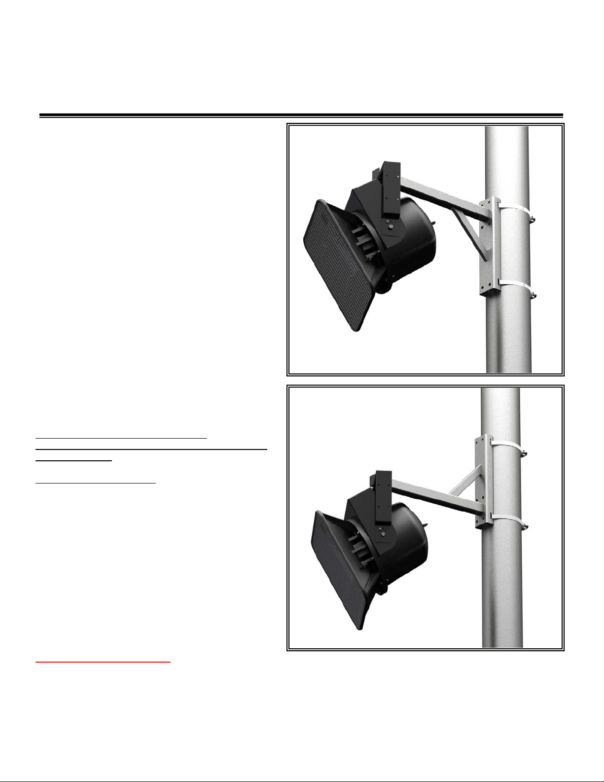
PoleStar™ PM-24-6UP-G
6” & Up Pole Mount with 24” long Arm
Installation Instructions
The PoleStar™ PM-24-6UP-G all-weather, galvanized steel pole
mount is designed to mount loudspeakers and other equipment
from vertical surfaces and columns. The PoleStar™ PM-24-6UP-G
accommodates many standard mounts for a wide variety of
mounting solutions, including, yokes, U-Brackets and the
PoleStar™ dual Adapter for mounting and aiming three
loudspeakers.
The universal strap kit provides a banding system to attach the PM24-6UP-G Pole Mount to vertical poles or columns from 6” diameter
and up.
Important: Mounting overhead system requires professional
experience. Improperly installed equipment can result in
property damage, personal injury, death and/or liability to the
installing contractor. Do not install if in doubt about the integrity of
the mounting structure.
Caution: Due to the wide variety of mounting structures,
environments, materials and mounting methods, the installing
contractor must exercise good judgment in selecting the proper
mounting area and hardware.
Follow these instructions for the most efficient and safest
mounting results.
Do not exceed the working load limit of 300lbs/136 kg.
DO NOT use Pneumatic tool to tighten bolts.
Use Loctite to permanently secure nuts to bolts and prevent
loosening overtime.
Bolt Torque: 35-40 foot pounds
Package Contents:
1 pc. Pole Mount, 6” & Up w/ 24” arm 1 pc Friction gasket
1 pc ½-13 x 3.5 hex bolt
1 pc ½-13 x 4.5 hex bolt
1 pc ½-13 nylock nut
1 pc ½ split lock washer
1 pc ½ Flat washer
2 pcs 90” long banding strap
2 pcs Retaining bolt & block assy.
2 pcs Flat washer, 3/8 SAE
1 pc Loctite #262
1 pc Instruction sheet
Install Banding Strap Kit:
Step 1: Assemble Fixed Retainer Block from the Band Kit
Mark the strap at least 4-6 inches from the end and fold the strap at the mark. Strike the strap at the bend to create a sharp radius. Slide the strap
through the Fixed Retainer Block so that its bend will pass over the beveled end of the Block. (Figure 1)
© 2011 Allen Products Company, Signal Hill, CA 90755 USA (562) 424-1100 REV00-020111
Page 2
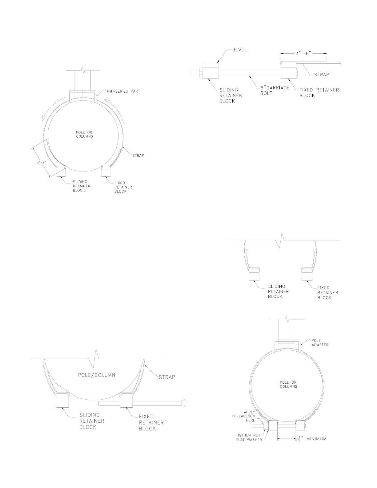
Step 2: Assemble the PM-24-6UP-G to the strap
Insert the free end of the strap through the slots on the side of the pole
mount channel, then through the Sliding Retainer Block, non-beveled
end first (Figure 2).
Step 3: Determine Strap length for Pole
Holding the Fixed Block firmly against the pole, overlap the strap. Move the Sliding
Retainer Block up against the Fixed Retainer Block so that their two beveled edges
meet each other (Figure 2).
Step 4
Move the Sliding Retainer Block back at least 1”-2” and fold the strap at the Sliding
Retainer Block’s beveled end. Strike the bend to form a sharp radius. Trim away the
excess strap material leaving 6” or more of left over material. A Longer tail length
provides more effective locking. Feed any excess strap material through the
Figure 2
Step 5
Bend the strap at both Retainer Blocks, near the non-beveled ends to allow the
Carriage Bolt to easily pass through the Retainer Blocks (Figure 3 and 4).
Pole mount slots, if necessary.
Step 6
Place the strap assembly around the pole, at the final mounting height and secure
the Retaining Blocks with the Carriage Bolt, Flange Nut and Flat Washer. Be sure
that the Pole Adapter is oriented into the right direction and with the bolt assembly
on the opposite side of the Pole Adapters (Figure 2 and 4).
Step 7
Tighen the Carriage bolt assembly until all slack has been removed from the fully
loaded assembly. Retainer blocks must have a minimum of 1/2” gap after fully
tighten. Do not over tighten (Figure 5).
Figure 4
Figure 1
Figure 3
Figure 5
© 2011 Allen Products Company, Signal Hill, CA 90755 USA (562) 424-1100 REV00-020111
Page 3

Single Speaker Mount:
Step 8: Attach a Speaker Mount to the Arm.
Attach the selected mount’s center hole to the
selected extension arm’s hole using the included ½13 x 3.5” or 4.5” long hex bolt, split lock washer,
fender washer, friction washer, and Nyloc nut.
Length of bolts to use depends on the type of
mounts being installed. Make sure the friction
washer is placed in between the arm and the mount
(Figure 6). Rotate mounts/speaker assembly to
desired angle then tighten bolts permanently.
Notes:
Holes on extension arm are 24”, 21” and 18” from
pole adapter.
Step 9: Install and Aim Speaker(s)
Following the instructions of the mount, install and
aim loudspeaker then tighten hardware and angles
permanently.
Step 10: Install End Caps
After installation, cover the end of the arm with the
provided 2 x 2 end cap. Trim end caps if necessary
to clear bolts head and washers.
Step 11: Install Safety Cable
Secure a safety cable to the pole or column and then
attach the other end of the safety cable to the
speaker to bypass the mounting system.
Figure 6
Triple Speaker Mounts:
Step 12: Install Dual Adapter
Install dual adapter to the two holes above extension arm
or in between the extension arm and the support brace
using the hex bolt, flat washer and Nyloc nut provided
with the Dual adapter Kit (Figure 7 and 8).
Note:
Install dual adapter to pole mount before installing to
poles or columns.
Step 13:
Install Pole Mount and dual adapter assembly to poles or
columns (Refer to Step 1-7).
Step 14:
Install the selected speaker mounts on the Pole Mount’s
extension arm and at the ends of the Dual Adapter using
the hex bolts, flat washer, friction washer, split washer
and Nyloc nut provided with the Pole Mount and the Dual
Adapter (Figure 9).
Note:
Make sure speakers mounted on both ends of the dual adapter are of the same weights or with in the same weights.
© 2011 Allen Products Company, Signal Hill, CA 90755 USA (562) 424-1100 REV00-020111
Page 4

Step 15: Install Safety Cable
Secure a safety cable to the pole or column, and then attach the other
end of the safety cables to the speakers to bypass the mounting
system.
Figure 7
Figure 8
Figure 9
© 2011 Allen Products Company, Signal Hill, CA 90755 USA (562) 424-1100 REV00-020111
 Loading...