

Page 1
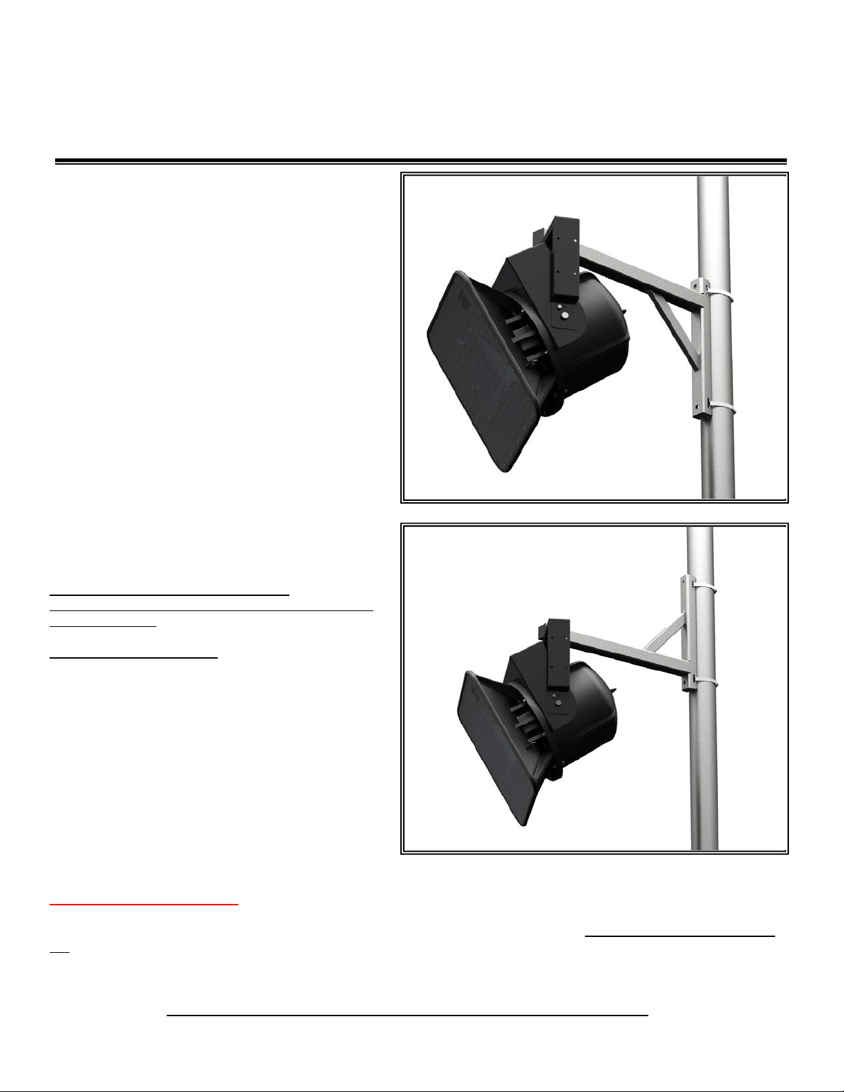
PoleStar™ PM-24-6DOWN-G
2” to 6” Pole Mount with 24” long Arm
Installation Instructions
The PoleStar™ PM-24-6DOWN-G all-weather, galvanized steel
pole mount is designed to mount loudspeakers and other
equipment from vertical surfaces and columns. The PoleStar™
PM-24-6DOWN-G accommodates many standard mounts for a
wide variety of mounting solutions, including, yokes and UBrackets.
The universal strap kit provides a banding system to attach the PM24-6DOWN-G Pole Mount to vertical poles or columns from 2” up
to 6” diameter.
Important: Mounting overhead system requires professional
experience. Improperly installed equipment can result in
property damage, personal injury, death and/or liability to the
installing contractor. Do not install if in doubt about the integrity of
the mounting structure.
Caution: Due to the wide variety of mounting structures,
environments, materials and mounting methods, the installing
contractor must exercise good judgment in selecting the proper
mounting area and hardware.
Follow these instructions for the most efficient and safest
mounting results.
Do not exceed the working load limit of 300lbs/136 kg.
DO NOT use Pneumatic tool to tighten bolts.
Use Loctite to permanently secure nuts to bolts and prevent
loosening overtime.
Bolt Torque: 35-40 foot pounds
Package Contents:
1 pc Pole Mount, 6DOWN” w/ 24” arm
1 pc ½-13 x 3.5” long hex bolt
1 pc ½-13 x 4.5” long hex bolt
1 pc ½-13 nylock nut
1 pc ½ split lock washer
1 pc ½ Flat washer
2 pcs 20” long 1/2“ wide banding strap
2 pcs Scru seal housing and rack assembly
1 pc Friction gasket
1 pc Loctite #262
1 pc Instruction sheet
Install Banding Strap Kit:
Step 1
Insert one end of the strap into the rectangular slot of the housing then fold at least two inch long or longer (a longer fold creates a more effective
lock) then flatten band using thumb to form a hook. The folded end should be on the opposite side of the housing’s screw head (Figure 1).
Step 2
Insert the end of the rack into the housing and rotate screw head clockwise using a screw driver until 3/4” of the rack comes out on the other end of
the housing (Figure 2). MAKE SURE THAT THE WORD “THIS SIDE UP” WRITTEN ON THE RACK IS FACING OUT.
© 2011 Allen Products Company, Signal Hill, CA 90755 USA (562) 424-1100 REV00-020211
Figure 1:
Page 2

Step 3
Insert the other end of the band through the slots of the PM-MOUNT-6DOWN-G
and out on the other side. Wrap the band snugly around the pole until the end
reaches rectangular slot of the rack (Figure 3).
Step 4
Measure, mark and cut the band at least one inch beyond the first serration of the
rack, then bend at least a one inch hook toward underside of band (Figure 4 & 5).
Step 5
Insert the hook into the rectangular slot of the rack, if necessary loosen the rack
from the housing. Flatten band with thumb to form a clamp (Figure 4).
Step 6
Position the location of the PM-MOUNT-6DOWN-G on the pole and then tighten
screw using screw or wrench to desired tension and complete the banding
operation (Figure 5).
Step 7
Repeat steps 1 to 6 for the lower banding strap
assembly.
Note: Optional
To strengthen banding strap use two straps on
each slot of the PM-MOUNT-6DOWN-G
Figure 1
Figure 2
Figure 3
© 2011 Allen Products Company, Signal Hill, CA 90755 USA (562) 424-1100 REV00-020211
Page 3

Figure 4
Install Speaker Mount:
Step 8: Attach a Speaker Mount to the Arm.
Attach the selected mount’s center hole to the selected extension arm’s hole using the included ½-13 x 3.5” or 4.5” long hex bolt, split lock washer,
fender washer, friction washer, and Nyloc nut. Length of bolts to use depends on the type of mounts being installed.
placed in between the arm and the mount (Figure 6). Rotate mounts/speaker assembly to desired angle then tighten bolts permanently.
Notes:
Holes on extension arm are 24”, 21” and 18”
from pole adapter.
Step 9: Install and Aim Speaker(s)
Following the instructions of the mount, install
and aim loudspeaker then tighten hardware
and angles permanently.
Step 10: Install End Caps
After installation, cover the end of the arm
with the provided 2 x 2 end cap. Trim end
caps if necessary to clear bolts head and
washers (Figure 6).
Step 11: Install Safety Cable
Secure a safety cable to the pole or column
and then attach the other end of the safety
cable to the speaker to bypass the mounting
system.
Figure 5
Make sure the friction washer is
Figure 6
© 2011 Allen Products Company, Signal Hill, CA 90755 USA (562) 424-1100 REV00-020211
 Loading...