

Page 1
MultiMount™ MM-120
Universal Wall Mount Installation Instructions
Thank you for selecting the MultiMount™ MM-120 wall mounting kit. This mounting kit
mounts and positions loudspeakers and video displays weighing, up to 120 lbs/55 kg.
from most vertical structures. The MM-120 simplifies and speeds up installations while
offering a very versatile range of aiming.
Warning:
Mounting and/or rigging equipment requires experienced professionals.
Improperly installed loudspeakers can result in property damage,
personal injury, death and/or liability to the installing contractor.
Note to installing contractor:
Due to the wide variety of wall structures, materials and mounting methods, these
instructions assume that the installing contractor will exercise proper judgment in
selecting the mounting area and hardware.
As a guide, the installation, when complete should be capable of supporting 5 to 10
times the actual applied load. Also, always use a back up safety system such as a
safety cable.
To assure a trouble free installation, read through and follow these instructions carefully
before beginning. If you have doubts about the integrity of the structure you are
mounting to or you are not sure about the proper hardware to use, consult a structural
and/or hardware specialist.
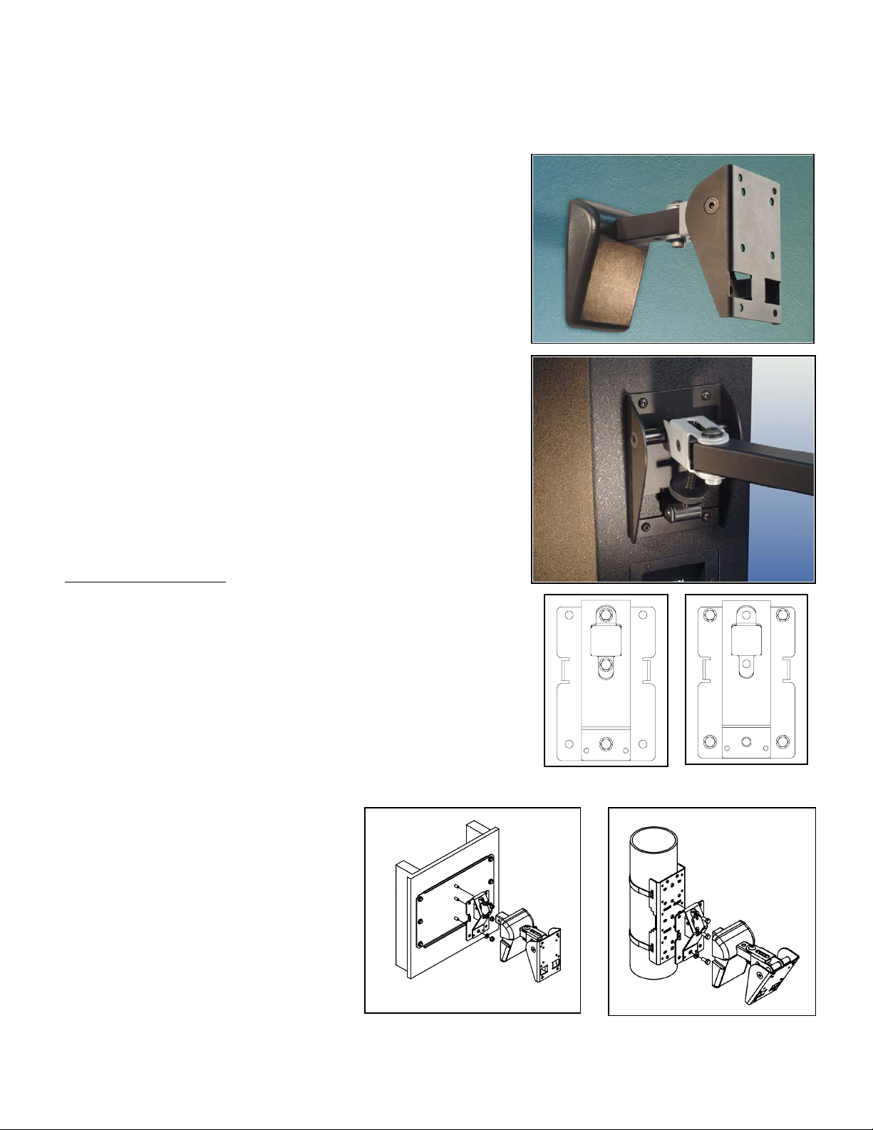
Be sure that all of the following items are included in this kit before proceeding:
Item #: Qty Description
1. 1 pc. Wall plate
2. 1 pc. Speaker adapter assembly
3. 1 pc. Support arm
Step 1:
If the optional Stud Brace Plate is selected to bridge the MultiMount between two
structural wall studs, install this in the desired area now then
bolt MultiMount directly to the bridge (Figure 3).
If the optional Pole Adapter Plate is selected to mount the
MultiMount to a radial surface, install this in the desired area now then bolt
MultiMount directly to the pole adapter (Figure 4).
Detach the wall mounting plate from the support arm by
removing the bolt, washers and nut securing the
support arm to the wall mounting plate. Place the
mounting plate over the signal wire exit and attach it to
the wall with the appropriate hardware for the
application. If in doubt, consult a local hardware
specialist (Figure 5).
Step 2:
Attach the adapter plate support arm assembly to
the appropriate mounting holes of the loud
speaker or video display using the manufacturer’s
suggested screws and washers. Tighten these
fasteners permanently (Figure 6). If threaded
mounting points are not included in the speaker
or display, consult the manufacturer for proper mounting procedures.
Figure 3
Figure 1--3 pt. Installation Figure 2 – 4 pt. installation
Figure 4
© 2004 Allen Products Co., Inc. Signal Hill, CA 90755 (562) 424-1100 REV.01-101408
Page 2
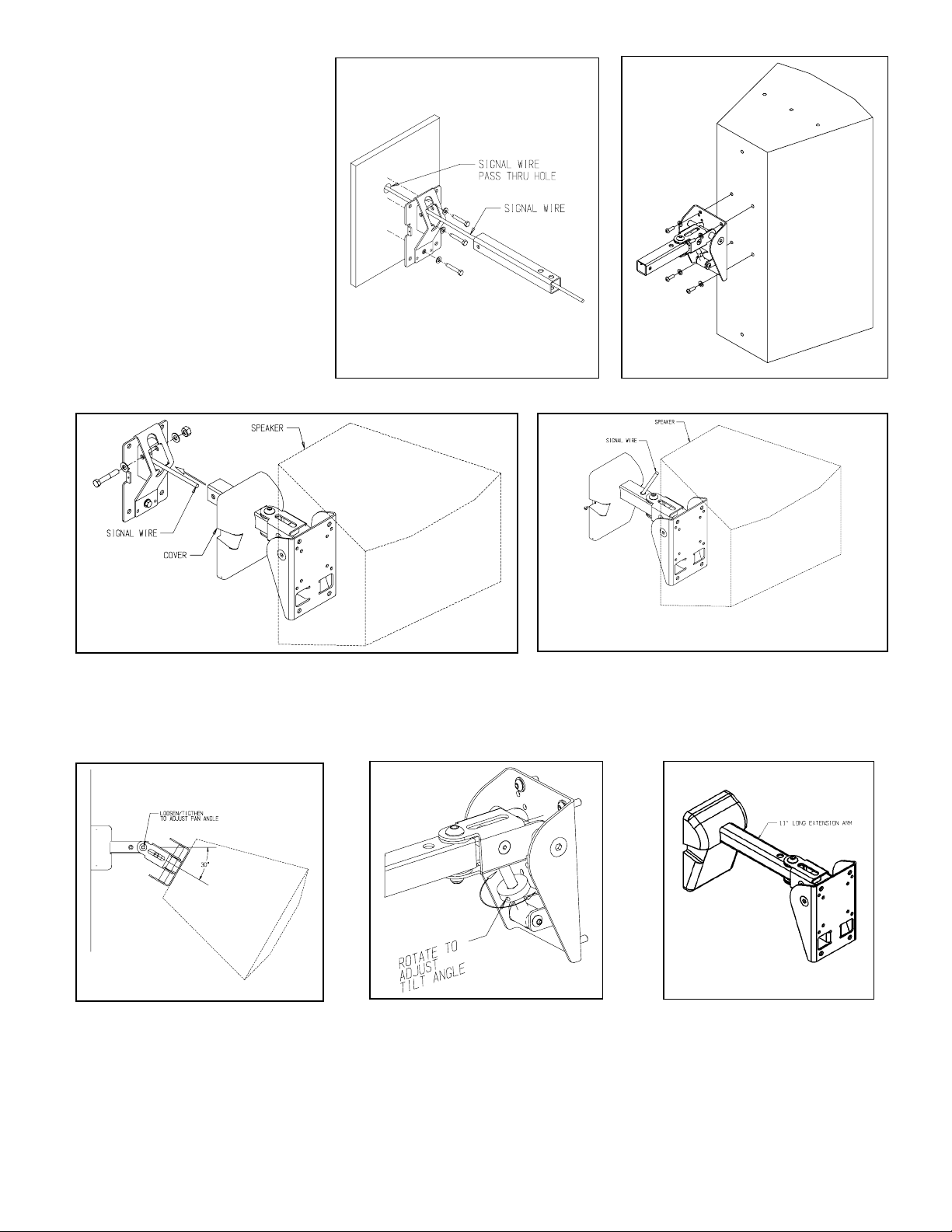
Step 3:
Lift object with the mount attached up to the
wall mounting plate and insert the support
arm into the opening of the wall mounting
plate (Figure 5). Line up the support arm’s
hole with the wall mounting plate’s hole and
insert the 3/8” x 2 1/2” tap bolt. Permanently
secure with 3/8” flat washer and nut
(Figure 7 and 8).
Figure 5
Figure 6
Figure 7 Figure 8
Step 4: Setting the pan angle
Rotate the speaker or video display horizontally, right or left, until it is aimed in the desired direction. Permanently tighten the socket head screw
at the support arm with a 5/16” hex wrench (Figure 9).
Top View
Figure 9
Step 5. Setting the tilt angle
While supporting the weight of the speaker, rotate the tilt control knob until the desired tilt angle is achieved (Figure 10). Caution;
ATTEMPT TO ADJUST THE SPEAKER OR VIDEO DISPLAY UPWARD, ABOVE THE HORIZONTAL POSITION.
Step 6. Recommendation: Install Safety Cable
Attach a safety cable (sold separately) to the mounting surface (Must be able to support at least five times the weight of the speaker), then attach
the other end of the safety cable to the speaker. If no attachment is provided on speaker, consult speaker manufacturer for advice on best
attachment point and method.
Figure 10
Figure 11
DO NOT
© 2004 Allen Products Co., Inc. Signal Hill, CA 90755 (562) 424-1100 Rev. 01-101408
 Loading...