

Page 1
MultiMount™ MM-024
Speaker Wall and Ceiling Mount Installation Instructions
Thank you for selecting the MultiMount™ MM-024 speaker Mounting kit. This
mounting kit contains one speaker mount that positions speakers weighing up
to 60 lbs/27 kg. from most wall and ceiling structures. The MultiMount-022
simplifies and speeds up wall and ceiling speaker installations while achieving
a very versatile range of speaker positioning.
Warning:
Mounting and/or rigging loudspeakers requires experienced professionals.
Improperly installed loudspeakers can result in property damage,
personal injury, death and/or liab i lity to the installing contract o r .
To assure a trouble free installation, read through and follow these
instructions carefully before beginning. If you have doubts about the integrity
of the structure you are mounting to or you are not sure about the proper
hardware to use, consult a structural and/or hardw are specialist.
Be sure that all of the following items are included in this kit before
proceeding.
Item# Qty. Description Item# Qty. Description
1. 1 pc. Mounting plate 5. 2 pcs. 3/4" ext. star lock washer
2. 1 pc. Speaker adapter plate 6. 1 pc. 5/16-18 x 1” socket screw
3. 1 pc. Support arm Assy. 7. 1 pc. 1/4” dia. x 3/4” stop pin
4. 2 pcs. 3/4"-16 x 1.00" Hex bolt 8. 1 pc. 5/16" flat washer
Note to installing contractor:
Due to the wide variety of wall structures, materials and mounting methods, these instructions
assume that the installing contractor will exercise proper judgment in selecting the mounting area
and hardware.
As a guide, the installation, when complete should be capable of supporting 5 to 10 times the
actual applied load. Also, use a back up safety system such as a safety cable.
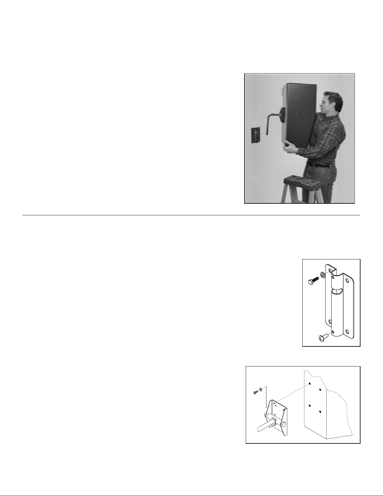
Step 1
(A) Mounting to a wall
Attach the mounting plate to the wall with the open center slot towards the ceiling using the
appropriate hardware for the application (Figure 1). If in doubt, consult a local hardware
specialist. Push the stop pin into the lower center hole of the wall plate (Figure 1).
(B) Mounting to a ceiling
Predetermine the desired direction of the speaker. Attach the mounting plate
to the ceiling structure with the open center slot towards the speaker using
the appropriate hardware for the application. Push the stop pin into the lower
center hole of the wall plate.
Step 2.
Attach the speaker adapter plate to the appropriate mounting holes of the
speaker using the manufacturer’s suggested screws and washers. Tighten
these fasteners permanently.
If threaded inserts are not included on the
speaker, consult the speaker manufacturer for proper mounting procedures.
Figure 1
Figure 2
2002 APC Incorporated, Signal Hill, CA 90755 USA (562) 424-1100 07/24/02
Page 2
T
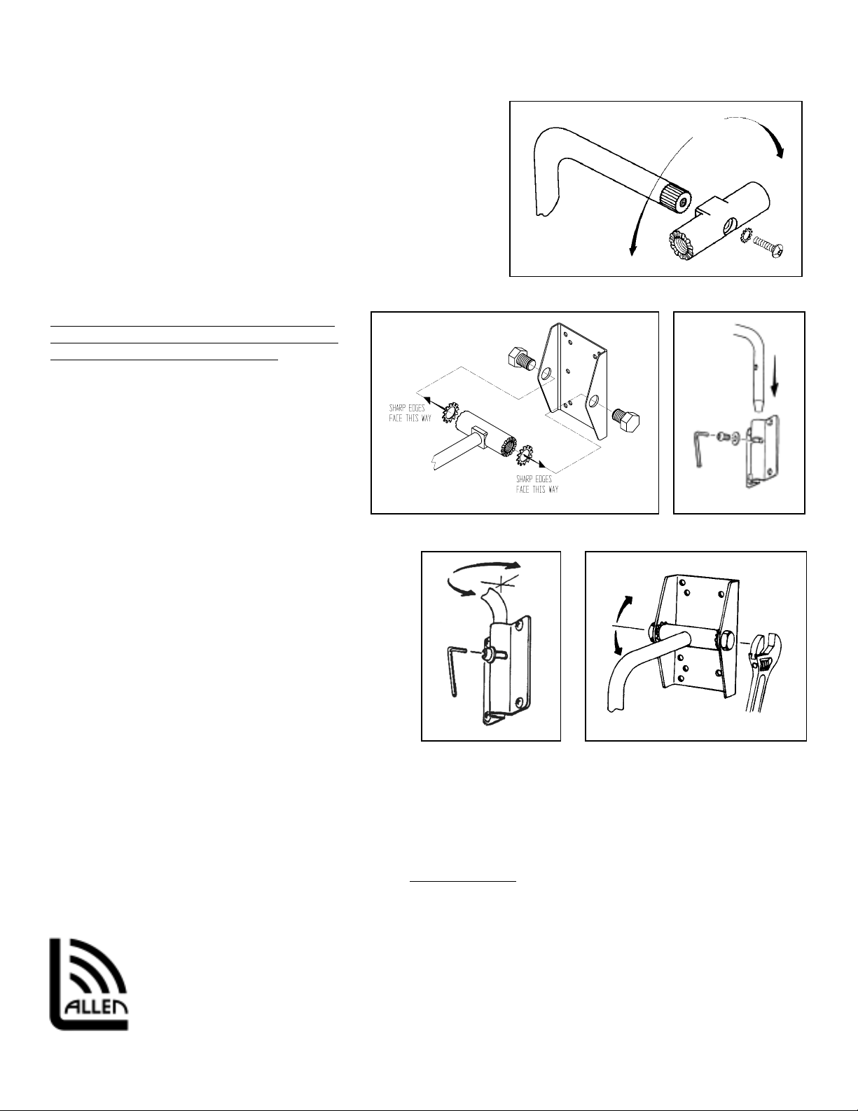
Step 3.
For vertical applications, use the support arm with the pivot rod
attached to the support arm as is. For horizontal (no tilt) installations,
remove the pivot rod from the support arm assembly by removing the
socket head screw (Figure 3). Reattach the pivot rod at the desired
angle then secure permanently with the socket screw.
Step 4.
Assemble the support arm to the adapter plate by bolting the pivot rod
inside the flanges of the speaker adapter plate with the star washer in
between the flange and the pivot rod. The rounded surface of the star
washer’s teeth must seat against the pivot rod (Figure 4).
Important:
The sharp edges of the star washer must face
the inside surface of the speaker adapter plate
flanges to achieve proper tilt locking.
Step 5.
Thread the 3/4”-16 hex bolt through the side
holes of the adapter plate’s flanges and into the
pivot rod. Position the support arm perpendicular
to the adapter plate then tighten securely but not
permanently. This will hold the speaker in
position while mounting it to the wall or ceiling
(figure 4).
Step 6
Lift the speaker and support arm up to the
mounting plate and insert the arm through the end of the
mounting plate with the cross slot (Figure 5). Line up the
support arm’s threaded hole with the cross-slot. Insert
the 5/16” socket screw and 5/16” flat washer through the
mounting plate’s slot and into the threaded hole of the
support arm. Tighten the screw firmly but not
permanently (figure 5). Be sure the flat washer seats
outside the slot.
Step 7.
Loosen the socket screw on the wall plate (do not
remove). Rotate the speaker horizontally right or left
until the speaker is aimed in the desired direction.
Permanently tighten the socket screw at the mounting
plate with a 3/16” hex wrench (figure 6).
Step 8.
While supporting the speaker’s weight, loosen the 3/4” hex bolts at the sides of the speaker adapter plate (do not
remove). Lift the speaker up to the desired tilt angle and hold it in position
that the screws have been tightened permanently before releasing the weight of the speaker (Figure 7).
Setting the pan angle
Setting the tilt angle
Figure 6 Figure 7
Figure 4 Figure 5
while re-tightening the 3/4” hex bolts. Be sure
Figure 3
If the tilt angle needs to be adjusted,
Allen Products Company Inc.
DO NOT PULL ON SPEAKER
, rather repeat step 8.
1635 E. Burnett Street
Signal Hill CA 90755 USA
el: (562) 424-1100 Fax: (562) 424-3520
Web Site: www.allenproducts.com
2002 APC Incorporated, Signal Hill, CA 90755 USA (562) 424-1100 07/24/02
 Loading...