

Page 1
LTMB24-X2-RK
Installation Instructions LT MB24 2 Wide Rigging Kit Grid
Thank you for choosing the LTMB24-X2-RK Grid. The LTMB24X2-RK Rigging Kit suspends two BOSE LTIII MB24 speakers in
2 wide arrangements.
Important:
Rigging overhead system requires professional experience.
Improperly installed equipment can result in property
damage, personal injury, death and/or liability to the
installing contractor. Do not suspend if in doubt about the
integrity of the structure.
Caution: Due to the wide variety of structures, environments,
materials and rigging methods, the installing contractor must
exercise good judgment in selecting the proper mounting area
and hardware.
Follow these instructions for the most efficient and safest
rigging results. Do not exceed the working load limit of
1000 lbs/455 Kg.
Package Contents:
2 pcs. LTMB24-X2-RK GRID
1 pc. Instruction sheet, 8.5X11
8 pcs Hex Cap, 3/8-16x1.5,G8, blk
8 pcs. Split washer, 3/8, G8, blk
8 pcs. Flat washer, 3/8”, SAE
4 pcs. Nyloc nuts, ½-13
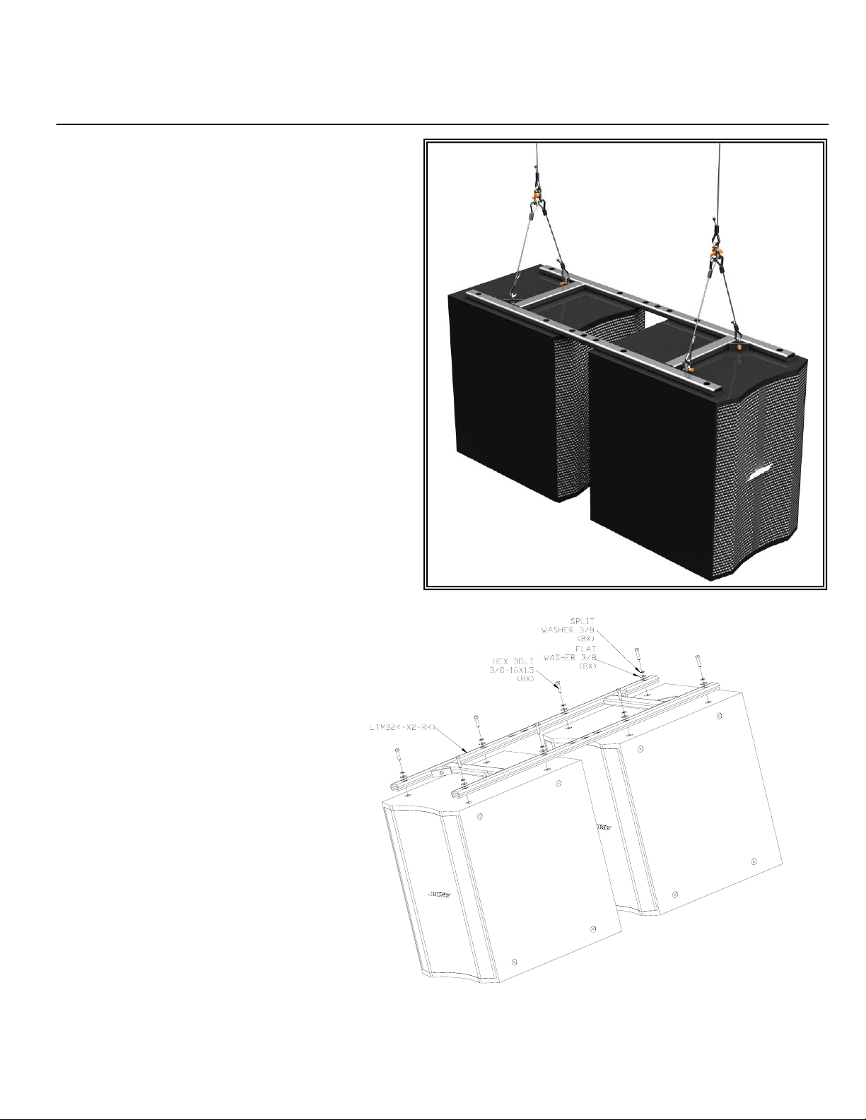
Step 1:
Check to make sure the holes of the grid matches
the holes on top and bottom of the speaker.
Remove and discard speaker screws where the
grid will be attached
Step 2:
Set two speakers on the clean or padded floor with
the front facing the same direction. Lay the grid
over the top of the speakers and match the holes
to the holes on the speaker. Attach grid to
speakers using the supplied 3/8 hex bolt, washer
and split washers. Tighten bolts permanently
(Figure 1).
Step 3:
Attach load rated suspension cables to the
suspension bracket on the four corners of the grid
using load rated hardware such as shackles
(Figure 2). One can use four cable suspension
points or four points bridled to a two point
suspension.
© 2008 ATM FLY-WARE Signal Hill, CA 90755 USA (562) 424-1100
REV01 –Revised illustration and steps of installation-022510
Figure 1
Page 2
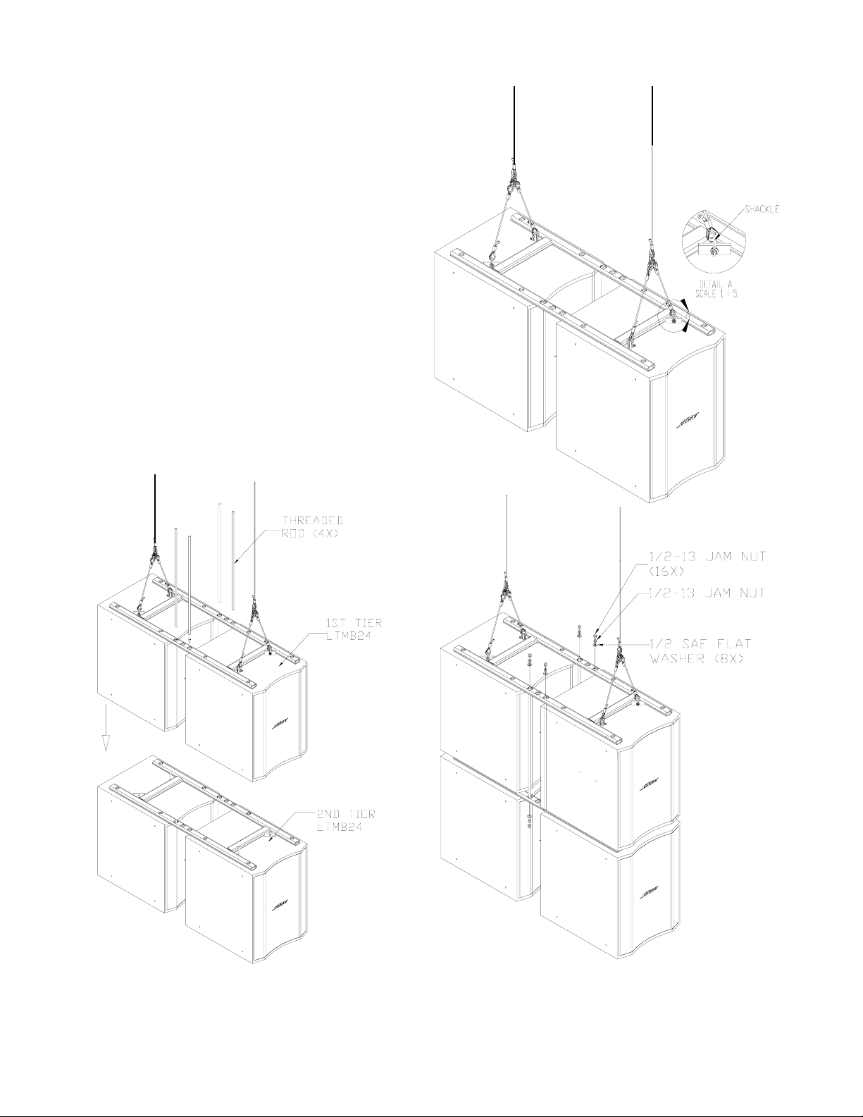
Step 4:
Check all connections before suspending the speaker cluster.
nd
Step 5: Connecting the 2
Repeat step 1 and 2 for the 2
Tier of LTMB24 loudspeaker
nd
tier of speaker (Figure 1)
Step 6:
Lift up the first tier of LTMB24 loudspeakers and place it on
top of the second tier of loudspeakers. Align the frames so
that the top and bottom frame’s center ½” dia. holes match
up.
Step 7: Install LTMB24-ROD-KT (sold separately)
Securely join the top and bottom tier by bolting the frames
together using a ½” threaded rod, flat washers and jam nuts
(LTMB24-ROD-KT sold separately). Insert the threaded rod
from the hole of the top frame and into the bottom frame. Use
the four corner hole. Apply lock-tite liquid solution on the nuts
then secure both ends of the threaded rods with flat washer
and two jam nuts (two jam nuts per end). Tighten nuts
permanently until frame and loudspeakers are tightly secured
(Figure 3 and 4).
Figure 2
Figure 3
Figure 4
© 2008 ATM FLY-WARE Signal Hill, CA 90755 USA (562) 424-1100
REV01 –Revised illustration and steps of installation-022510
 Loading...