

Page 1
FASPAC
The FP-FRI-1X2 Line array kit give designers, contractors and audio consultants the
ability to create a two FRI122+ or FRI152+ speaker in a tight pack configurations. The
FasPac
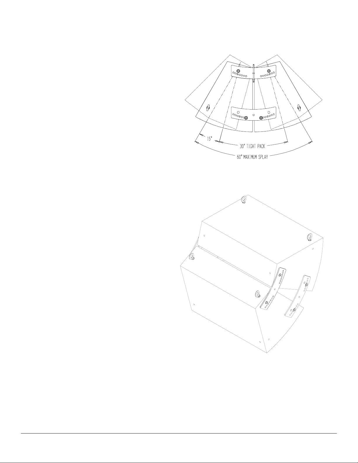
allowing cabinets to be adjusted relative to each other to find the optimum sound
directivity. A series of holes are provided to easily adjust the splay angle from 0° to
30° at an increment of 2.5 degree.
Installing speakers must be performed by experienced professionals
about the integrity of the structure you are mounting or suspending to or not sure
about the proper hardware or method to use, consult a certified rigging company.
Package contents:
4 pcs 6-0101 Front Joiner Plate
8 pcs Btnhd sckt screw, 3/8-16x1.5” long
12 pcs 3/8 flat washers
CAUTION: PLEASE READ CAREFULLY BEFORE PROCEEDING
Due to the wide variety of building structures, materials and suspension methods,
these instructions assume that the installing contractor/installer will exercise good
judgment in selecting the proper mounting area and hardware. As a guide, the
installation, when complete, should be capable of supporting at least 5 times the
actual load. Follow building code requirements to safely suspend the speakers to the
building structure
Step 1.
Unscrew existing speaker screw and discard.
Step 2.
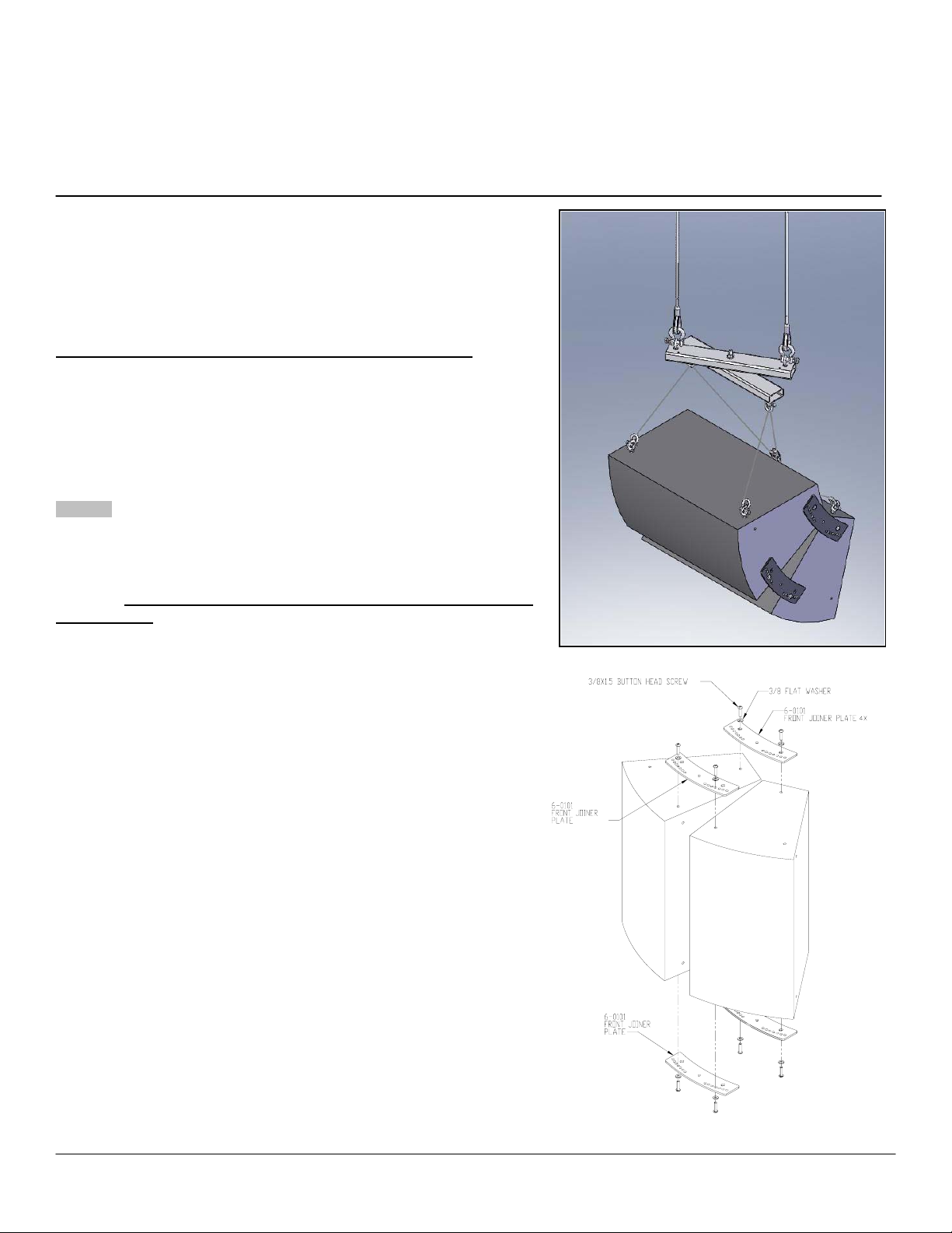
Determine the splay angle of the speaker and the holes to use on the front
joiner plate (Figure 2).
Step 3.
Install the front joiner plate on rear rigging inserts of the speaker using the
slots of the plate (Figure 1). Install another front joiner plate on the two front
rigging inserts using the corresponding holes for the appropriate splay
angles. Use the provided 3/8 screws and washers. Make sure the markings
on the plates are facing up. Do not tighten screws; leave it snug until all
plates are in position.
Step 4.
Slowly flip the speaker assembly up then repeat Step 3.
Step 5.
When all plates are in position, tighten all screws permanently.
Step 6.
Lay the speaker cluster on its side then install eyebolts to the side rigging
points (now top) of the speaker as shown (Figure 3). Install eyebolts on the
rear rigging points of the lower speaker.
TM
provides a method of flying a tight pack array while offering the capability of
TM
FP-FRI-1X2
. If in doubt
Figure 1
1X2 LINE ARRAY KIT
©2007 ATM Fly-Ware, Signal Hill, CA 90755 (562) 424-1100 08/07-R01
Page 2
Step 7.
Use the eyebolts on the top of the speaker cluster as the main speaker
suspension points. Use the lower eyebolts on the lower speaker for pull
back points to adjust the tilt angle of the speaker cluster assembly (See
main illustration).
Step 8.
Check all hardware connections before hoisting cluster.
Figure 2.
Figure 3.
©2007 ATM Fly-Ware, Signal Hill, CA 90755 (562) 424-1100 08/07-R01
 Loading...