

Page 1
AFGS SERIES AFGS SUSPENSION ARM
Installation Instructions for AFGS-14A, 18A, 24A, 30A and 36A (White)
Thank you for choosing the AFGS Arm Series. The AFGS arm is an
adjustable suspension arm for the AFGS Grid Series. Used with the
AFGS spoke, it suspends a speaker and provides front and rear
adjustability by sliding the connection point thought the center opening
of the spoke. The arm comes in different length from 14” to 36” long to
accommodate a variety of loudspeakers.
Important: Rigging overhead system requires professional experience.
Improperly installed equipment can result in property damage,
personal injury, death and/or liability to the installing contractor.
Do not suspend if in doubt about the integrity of the structure.
Caution: Due to the wide variety of structures, environments, materials
and rigging methods, these instructions assume that the installing
contractor will exercise good judgment in selecting the proper mounting
area and hardware.
Follow these instructions for the most efficient and safest
mounting results.
Do not exceed the working load limit:
AFGS-14A/W= 560 lbs/253 kg.
AFGS-18A/W=560 lbs/253 kg
AFGS-24A/W=410 lbs/186 kg
AFGS-30A/W=325 lbs/147 kg
AFGS-36A/W=265 lbs/120 kg
Package Contents:
1 pc. AFGS Arm 1 pc. Hex bolt,1/2 x 5.5” long
1 pc. Instruction sheet 2 pcs Flat washer, 1/2
1 pc. Spoke Clamp 4 pcs Nylock Nut, 1/2-13
Step 1: Check to make sure that the suspension arm is the right
length for the speaker and the grid being installed.
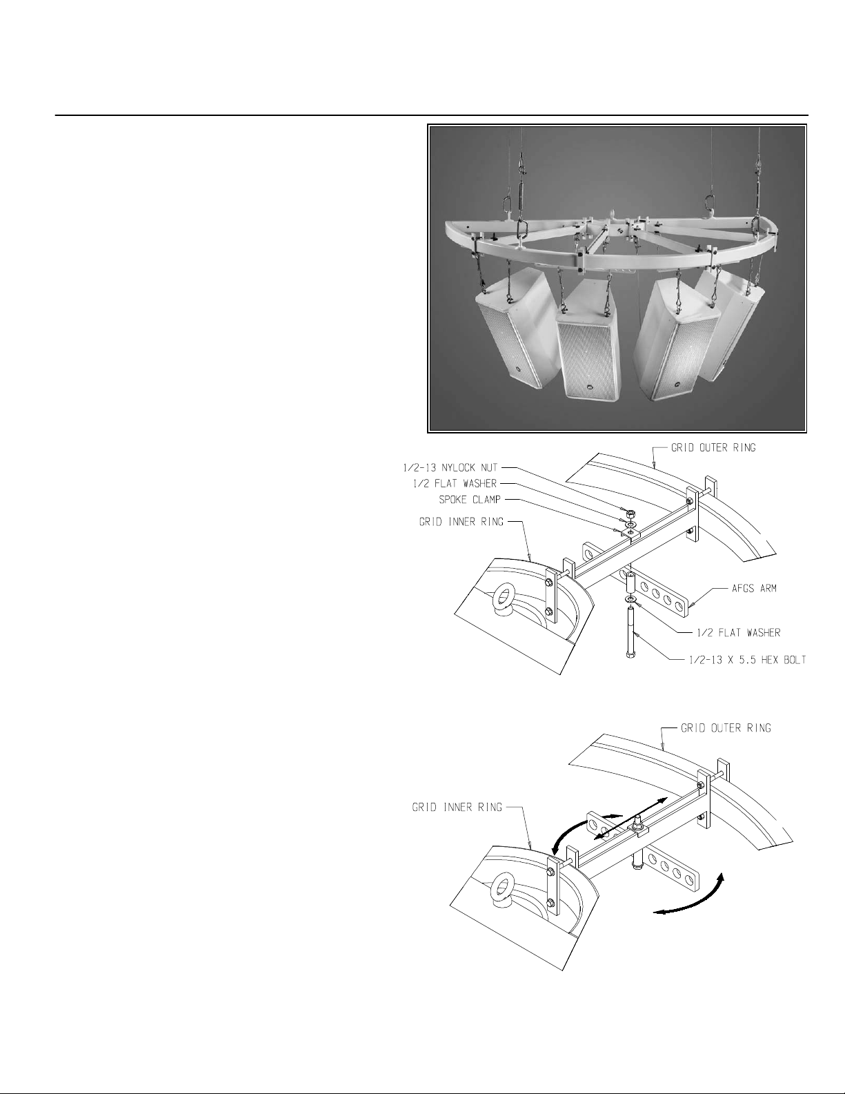
Step 2: Install AFGS Arm to Spoke:
Install the suspension arm to the bottom of the spoke. Align the
center hole of the arm to the opening of the spoke. Insert the hex
bolt with washer into the center hole of the arm, through the space
between the spoke then through the spoke clamp. Make sure that
the spoke clamp captures both bars of the spoke. Secure assembly
with a washer and a nylock nut (Figure 1). Do not tighten bolts.
Step 3: Adjust Arm.
Move the arm to desired location along the spoke by sliding forward
or backward. Adjust the horizontal angle of the arm based on the
spoke. Once arm is set on desired location and angle, tighten bolts
permanently (Figure 2)
Step 4: Suspend speaker
Suspend speaker to the holes of the suspension bar using the
appropriate hardware. Use the Radius bar behind the Grid’s inner
ring to attach the pull back cable.
Figure 1
Figure 2
 Loading...