

Page 1
p
4X4-UD55A-VWD
Assembly Installation Guide
Important: Assembling video displays is a serious
endeavor that requires experienced professionals.
Improperly assembled equipment can result in
property damage, injury and/or liability to the
installing contractor. Do not attempt to install this
equipment if any part of the assembly is in doubt.
Follow these instructions for the most efficient and
safest assemble results.
Do not attempt to install this product if any of the
parts listed below are missing. If parts are missing,
contact sales@adapttechgroup.com;
Package Contents:
7 pcs 9-0881 4X Left H-Slat
7 pcs 9-0883 4X Right H-Slat
2 pcs 9-0893 bottom Side H- slat
2 pcs 9-0895 bottom center H- Slat
12 pcs 9-0885 V-Channel Assembly
2 PCS 9-0890 Center V-Channel assembly
8 pcs 9-0888 Lock Arm Bracket
8 pcs 9-0806 Horizontal Joiner plate
6 pcs 9-0897 Vertical Joiner Plate
8 pcs Nylon/friction washer,.28 IDx.74OD, white
8 pcs Phil. Pan head screw, M4-12mm long
8 pcs Nyloc nut, M4
272 pcs Flat head phil. Screw, M6x20mm long
Left Frame (Figure 1A)
To
© 2013 Adaptive Technologies Group, Signal Hill, CA 90755 USA (562) 424-1100 Rev.00-040413
Top right Frame (Figure 1B)
Page 2
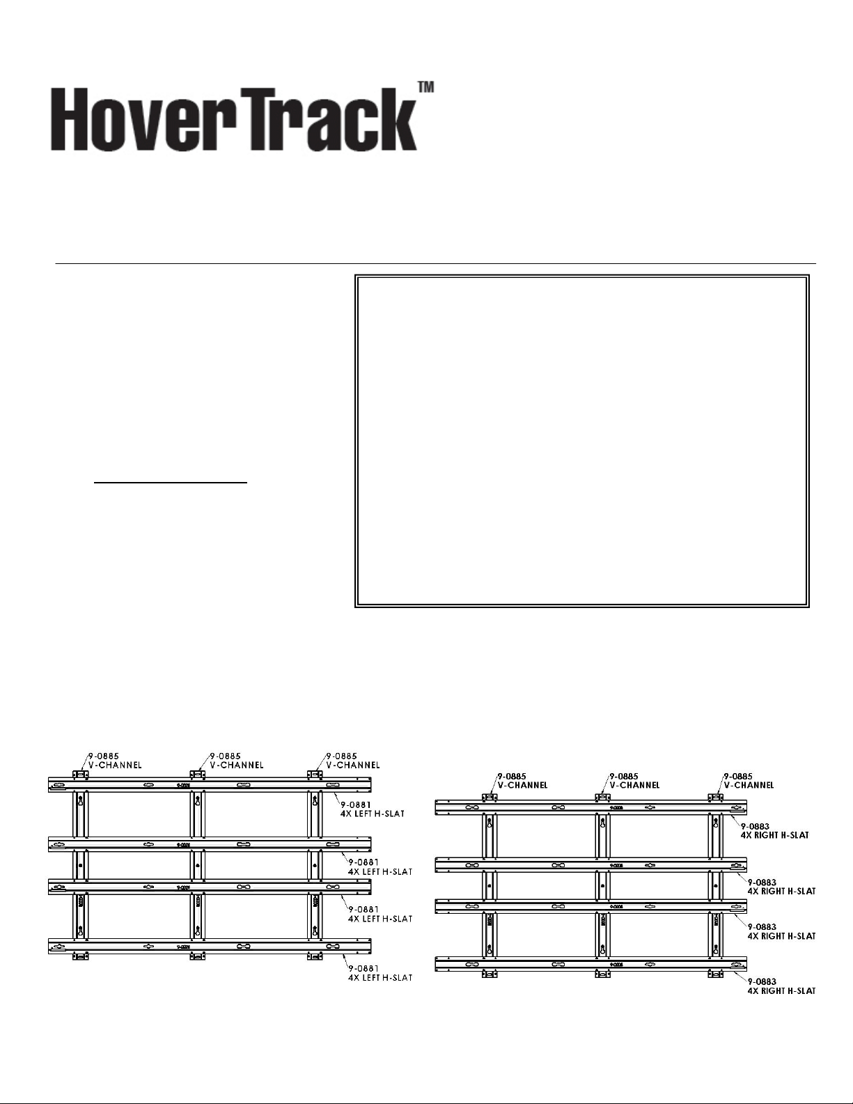
Step 1: Assemble Top Left Frame
Place all of the parts in figure 1A on the floor. Start with
three 9-0885 V-channels with their open side facing up with
the narrow part of the key holes slots facing up and all in the
same direction. Place four 9-0881 Left H-Slats over the Vchannels with the keyhole surface facing up and the fourhole patterns lining up with that of the channels (Figure 1A).
Rectangular slots in the ends of the slats should be at the
outer edge of the frame. (See figure 3).
Step 2: Assemble Top Right Frame:
Place all of the parts in figure 1B on the floor. Start with
three 9-0885 V-channels with their open side facing up with
the narrow part of the key holes slots facing up and all in the
same direction. Place four 9-0883 Right H-Slats over the Vchannels with the keyhole surface facing up and the fourhole patterns lining up with that of the channels (Figure 1B).
Rectangular slots in the ends of the slats should be at the
outer edge of the frame. (See figure 3).
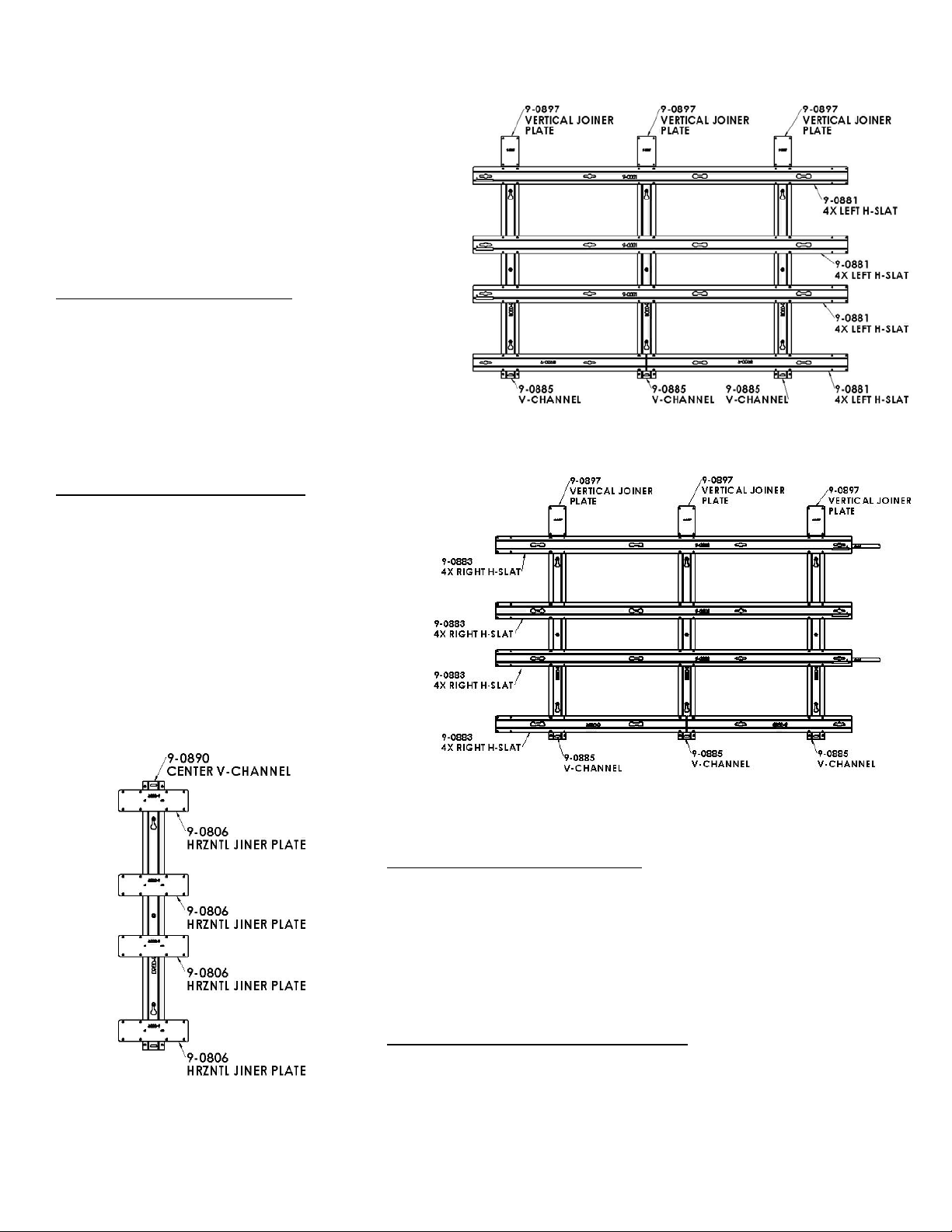
Step 3: Assemble Bottom Left Frame:
Place all of the parts in figure 1C on the floor. Start
with three 9-0885 V-channels with their open side
facing up with the narrow part of the key holes slots
facing up and all in the same direction. Place three 90881 H-Slats, one 9-893 bottom side H-slat and one 90895 bottom center H-Slat over the V-channels with
the keyhole surface facing up and the four-hole
patterns lining up with that of the channels. Place
three 9-0897 vertical joiner plates at the top of the Vchannels as shown in Figure 1C. Rectangular slots in
the ends of the slats should be at the outer edge of the
frame. (See figure 3).
Bottom Left Frame (Figure 1C)
Bottom Right Frame (Figure 1D)
Step 4: Assemble Bottom Right Frame
Place all of the parts in figure 1D on the floor. Start with three 9-0885 V-channels
with their open side facing up with the narrow part of the key holes slots facing up
and all in the same direction. Place three 9-0883 Right H-Slats, one 9-0893
bottom side H-slat and one 9-0895 bottom center H-Slat over the V-channel with
the horizontal keyholes facing up. Place three 9-0897 vertical joiner plates at the
top of the V-channels (Figure 1D). Rectangular slots in the ends of the slats
should be at the outer edge of the frame. (See figure 3).
Step 5: Assemble Center Joiner Assemblies:
Place one 9-0890 center v-channels on the floor, each with their opening facing
Figure 1E (Center Joiner Assembly)
up and with the narrow end of the keyhole slots facing up. Place four each 9-0806
Horizontal Joiner plates with thread side down over the 9-0890 center v-channel
as in Figure 1E and Figure 2.
© 2013 Adaptive Technologies Group, Signal Hill, CA 90755 USA (562) 424-1100 Rev.00-040413
Page 3
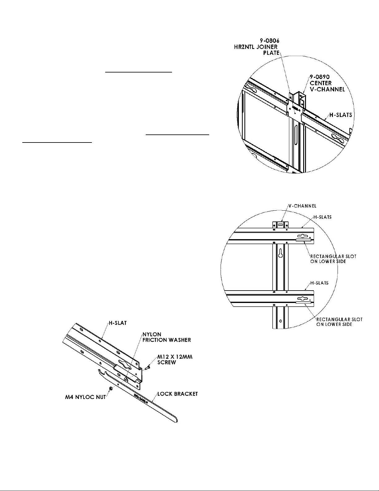
Step 6: Install Locking Arm brackets
Assemble the 9-0888 locking arm bracket on three of the 9-0881 left H-slat
and three on the 9-0883 right H-slat near the rectangular slot using the
provided M4 screws, nylon washer and nylock nut (Figure 4). The locking arm
brackets must be installed on the first, third, fifth and seventh horizontal Hslats starting from the top. Make sure the hook of the locking arm bracket
faces up (Figure 4 & 8). Tighten screw to increase locking arm friction.
Step 7: Assemble the Four Sections of the Frame
Assemble the top left frame by attaching the horizontal H-slats, (9-0881) to the
V-channels (9-0885) using the provided M6x20mm long flat head screws. Do
not tighten screws until all screws are installed. Check for squareness by
measuring corners to corners then tighten screws starting with the screws
on the holes of the H-slats (Figure 5)
Repeat step 7 for assembling the top right frame, lower left frame and lower
right frame (Figure 5). Install the Vertical joiner plate on the upper end vchannels of the lower frames using M6 flat head screws (Figure 5).
Step 8:
Figure 2
Join the top left frame and the top right frame together using the 9-0806
horizontal joiner plate and 9-0890 center joiner V-Channels (Figure 2 &
6). Tighten screws permanently.
Step 9:
Assemble the bottom left frame and the bottom right frame together
using the 9-0806 horizontal joiner plate and 9-0890 center joiner Vchannels (Figure 2 & 7). Tighten screws permanently.
Step 10:
For wall installation, refer to product installation guide.
Figure 3
Figure 4
© 2013 Adaptive Technologies Group, Signal Hill, CA 90755 USA (562) 424-1100 Rev.00-040413
Page 4

g
ure 5
Fi
Figure 6 (Upper/Top Frame)
© 2013 Adaptive Technologies Group, Signal Hill, CA 90755 USA (562) 424-1100 Rev.00-040413
Page 5

Figure 7 (Lower/Bottom Frame)
Figure 8
© 2013 Adaptive Technologies Group, Signal Hill, CA 90755 USA (562) 424-1100 Rev.00-040413
Page 6

4X4-UD55A-VWD
4 Wide x 4 Deep Video Wall Display Installation Guide
This display kit mounts Samsung UD55A LCD monitors
in a 4 wide by 4 deep landscape configurations. The
frame attaches to a wall and receives the LCD monitors
by way of four machined fittings (per monitor) that thread
into the monitor’s VESA holes. These fittings then insert
into the frame’s channels. The monitor’s fittings secure
to the frame with locking arms that provide an easy way
to remove the monitors for service. A removable panel
provides access for media players behind the frame.
Important: Installing video displays is a serious
endeavor that requires experienced professionals.
Improperly prepared walls and other structures as
well as the equipment being installed can result in
property damage, injury, death and/or liability to the
installing contractor. Do not proceed if any part of the
installation is in doubt.
Caution: Due to the wide variety of structures,
environments, materials and installation methods, the
installing contractor must exercise good judgment in
selecting the proper mounting area. The mounting
structure must be capable of supporting at least 5 times
the load of the installed equipment. Consult local
building codes for further guidance.
Follow these instructions for the most efficient and
safest mounting results.
Package Contents:
1 pc Upper Frame Assembly w/ locking arms
1 pc Lower Frame Assembly w/ locking arms
7 pcs Vertical Joiner bracket
64 pcs Adjustable VESA button (black)
42 pcs Adjustable Lag bolts, 5/16”
42 pcs Hex nuts, 5/16”
42 pcs Flat washer, 5/16
1 pc Instruction sheet
Notes:
Hardware to mount frames to wall is included.
4 Wide x 4 Deep Video Wall Display (Rear View)
© 2013 Adaptive Technologies Group, Signal Hill, CA 90755 USA (562) 424-1100 Rev.00-040513
Page 7

Step 1: Mount Upper Frame to Wall
Scribe a horizontal line on the wall
showing the exact location of where the
top edge of the upper left monitor will be.
Measure down 9.1” (231mm) from that
line and scribe another horizontal line
showing where the horizontal location of
the first adjustable lag bolt will be (Figure
1).
Scribe a vertical line showing where the
top left side of the upper monitor will be.
Measure to the right 16.9” (429.3mm) and
scribe another vertical line showing where
the vertical location of the first adjustable
lag bolts (Figure 1). Mark the intersection
of the vertical and horizontal lines.
Measure 157.7” (4005.6mm) to the right
for the location of the second adjustable
Figure 1
lag bolt. Use a long level to
make sure the second
location is horizontally
aligned to the first lag bolt
location (Figure 1). Mark the
second lag bolt location.
Measure 76.9” (1953.3mm)
to the right for the third
adjustable lag bolt. Mark the
third lag bolt location (Figure
1).
Pre-drill the marked lag bolt
Figure 2
locations using a 3/16” or
5mm drill bit.
Install the first, second and third adjustable lag bolts to the pre-drilled holes
until the hex part of the bolt is flush to the wall. A deep socket wrench maybe
required.
Step 2:
Hang the upper frame to the adjustable lag bolts (Two or three people
required). Install the provided hex nut and flat washer, level upper frame then
tighten the hex nuts.
Use the frame as a template to mark the other locations of the adjustable lag
bolts. Use three (3) per vertical channel, two keyholes and the center hole
(Figure 2).
Loosen and remove the hex nut and flat washer securing the upper frame to
the wall. Place the upper frame back on the floor. Pre-drill marked holes using
Figure 3
the 3/16” or 5mm drill bit then install the other adjustable lag bolts until the hex
part of the bolt is flush to the wall (Figure 2).
© 2013 Adaptive Technologies Group, Signal Hill, CA 90755 USA (562) 424-1100 Rev.00-040513
Page 8

Hang the upper frame onto the adjustable lag bolts
mounted on the wall. Install hex nut and flat washer then
snugly tighten hex nuts. DO NOT TIGTHEN permanently
until the entire video frame is installed and adjusted
(Figure 3).
Step 3: Attach Lower frame to Upper Frame
Align vertical joiner brackets from the lower frame to the
bottom of the upper frame’s vertical channel holes then
secure using the supplied M6 flat head screws (Figure
4). Snugly tighten screws only. Connect only the center
and the side vertical joiner plates.
Mark the locations of the adjustable lag bolts for the
lower frame. Three per V-Channels (Figure 2). Detach
the lower frame from the top frame by unscrewing the
screws on the Vertical joiner plate then place lower
frame back on the floor.
Pre-drill marked location using a 3/16” or 5mm drill bit
then install the adjustable lag bolts until the hex part is
flushed with the wall.
Figure 4
Step 4:
Hang the lower frame to the adjustable lag bolts on the wall
then connect all the vertical joiner plates to the bottom of the
upper frame. Tighten screw permanently. Install the flat
washer and hex nut onto the adjustable lag bolts then snugly
tighten (Figure 4).
Figure 5
Step 5:
Use a long level to plum the frame by rotating the adjustable lag bolts on
the V-channels using the provided adjustment wrench starting from one
side of the frame. Rotate counter clockwise to pull the frame forward and
clockwise to push the frame back towards the wall (Figure 5). Use a long
level, a straight edge or a piece of string secured on each side of the
frame to make the horizontal H-slat straight by adjusting the adjustable
lag bolts closest to the H-slat. Once the frame is plumed and leveled,
tighten all hex nuts permanently.
Step 6: Optional
Install Brackets to Media Player (Brackets not included)
Attach the media player brackets to the sides of the media player using
Figure 6
its existing side screws. Media player varies in sizes (Figure 6).
© 2013 Adaptive Technologies Group, Signal Hill, CA 90755 USA (562) 424-1100 Rev.00-040513
Page 9

g
Step 7: Optional
Install Media Player
Choose and remove the bottom left or right lower side H-slat by
unscrewing its flat head screws (Figure 7). Install the media player to
the wall in between the two vertical V-channels using the appropriate
fasteners for the media player’s bracket. Re-install the bottom lower side
H-slat (Figure 7).
Step 8: Install M8 VESA buttons to monitors
Thread the M8 adjustable VESA buttons to the VESA mounting holes in
the back of each monitor (Figure 8).
Step 9: Install Monitors to the Left Column
Lift up the locking arms on the left side of the frame. Starting with
the upper left monitor, connect power and signal wires to each
monitor then align its four Adjustable VESA buttons with the four
large slots in the H-slats then slide the monitor from left to right
until it stops. Pull down the locking arm to lock monitor into place
(Figure 9). Repeat step 9 for the three lower monitors.
Figure 7
Figure 8
ure 9
Fi
Figure 10
Step 10: Note on alignment:
While installing monitors, check for front and side alignment of
the monitors. The surfaces of all monitors must be aligned and flush to each other. If one or more screens are tilted more than others
use the adjustment wrench to reach the hex portion of the M8 adjustable VESA buttons at the rear of the monitor and rotate counter
clockwise to pull the front of the monitor forward or clockwise to push it back towards the wall. If access to the rear is not accessible
remove the screen(s) and depending whether the monitor needs to be tilted forward or backward rotate the buttons using the
adjustment wrench, a flat head screw driver or fingers (Figure 10). Reinstall and recheck surface alignments. Repeat where necessary.
© 2013 Adaptive Technologies Group, Signal Hill, CA 90755 USA (562) 424-1100 Rev.00-040513
Page 10

Step 11: Install Second Column Monitors
Starting with the top monitor, connect the power and signal wires to each monitor then align its four M8 adjustable VESA buttons with
the four large slots in the H-slats. Slide the monitor from right to left until it is snug against the left column monitor (Figure 11). Repeat
step 11 for the three lower monitors. Check for front and side alignments-refer to Step 10.
Step 13: Install Third Column Monitors
Repeat step 11 to install the third column monitors.
Step 14: Install Fourth Column Monitors
Lift up the locking arms on the right side of the frame. Starting with the upper
monitor, connect power and signal wires to each monitor then align its four
M8 adjustable VESA buttons with the four large slots in the H-slats. Slide the
monitor from right to left until it is snug against the next column monitor. Pull
down the locking arm to lock monitor into place (Figure 12).
Repeat step 12 for the lower three monitors. Check for front and side
alignments. Refer to Step 10.
Servicing Tips
First (Left) Column Monitor Removal
Reach fingers between the wall and the monitor and lift the locking arm to
unlock. Slide monitor to the left about 1.00” (25.4mm) until its VESA buttons
Figure 11
disengage from the frame, lift a little to support the weight of the monitor then
slowly pull to remove (Figure 13).
Second Column Monitor Removal
Reach fingers between the left-side wall and the monitor to the left of the
monitor being removed. Lift the locking arm to unlock then slide the monitor to
its extreme left position, about 1.5” (40 mm.) Slide the second column monitor
to the left until its VESA buttons disengage from the frame, lift a little to support
the weight of the monitor then slowly pull to remove.
Third Column Monitor Removal
Reach fingers between the right side wall and the monitor to the right of the
monitor being removed. Lift the locking arm to unlock then slide the monitor to
its extreme right position, about 1.5” (40 mm). Slide the third column monitor to
the right until its VESA buttons disengage from the frame, lift a little to support
the weight of the monitor then slowly pull to remove.
Fourth (Right)
Column Monitor
Removal
Reach fingers
between the wall and
the monitor and lift the
Figure 12
locking arm to unlock.
Slide the monitor to
the right until its VESA
buttons disengage
from the frame, lift a
little to support the
weight of the monitor
then slowly pull to
Figure 13
remove (Figure 13).
© 2013 Adaptive Technologies Group, Signal Hill, CA 90755 USA (562) 424-1100 Rev.00-040513
 Loading...