

Page 1
HoverTrack® Series 4X4-UD46A-VWD
Assembly Installation Guide
Important: Assembling video displays is a serious
endeavor that requires experienced professionals.
Improperly assembled equipment can result in
property damage, injury and/or liability to the
installing contractor. Do not attempt to install this
equipment if any part of the assembly is in doubt.
Follow these instructions for the most efficient and
safest assemble results.
Do not attempt to install this product if any of the
parts listed below are missing. If parts are missing,
contact sales@adapttechgroup.com;
Package Contents:
8 pcs 9-0802 4X Left H-Slat
8 pcs 9-0801 4X Right H-Slat
12 pcs 9-0803 2X V-Channel Assy.
2 PCS 9-0810 4X Center V-Channel assy.
8 pcs 9-0812 UD46A Lock Arm Bracket w/ hrdwr
8 pcs 9-0806 Horizontal Joiner plate
6 pcs 9-0814/9-0804 Vertical Joiner Plate
64 pcs M8 adjustable VESA buttons
1 pc1 Adjustment wrench
42 pcs Adjustable Wood screw Hanger stud
264 pcs Flat head phil. Screw, M6x20mm long
Top right Frame (Figure 1B)
© 2011 Adaptive Technologies Group, Signal Hill, CA 90755 USA (562) 424-1100 Rev.00-120712
Page 2
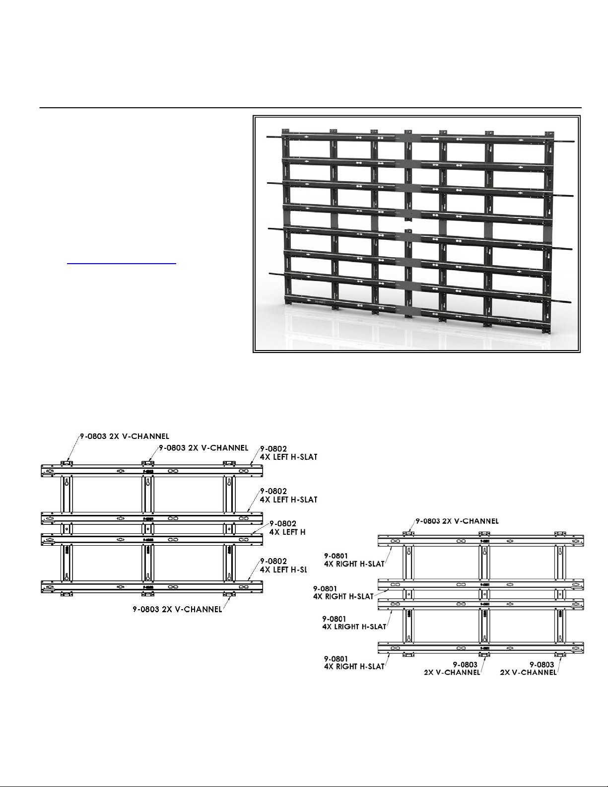
Step 1: Assemble Top Left Frame
Place all of the parts in figure 1A on the floor. Start with three
9-0803 2X V-channels with their open side facing up with the
narrow part of the key holes slots facing up and all in the
same direction. Place four 9-0802 Left H-Slats over the Vchannels with the keyhole surface facing up and the four-hole
patterns lining up with that of the channels (Figure 1A).
Rectangular slots in the ends of the slats should be at the
outer edge of the frame. (See figure 3).
Step 2: Assemble Top Right Frame:
Place all of the parts in figure 1B on the floor. Start with three
9-0801 2X V-channels with their open side facing up with the
narrow part of the key holes slots facing up and all in the
same direction. Place four 9-0801 Right H-Slats over the Vchannels with the keyhole surface facing up and the four-hole
patterns lining up with that of the channels (Figure 1B).
Rectangular slots in the ends of the slats should be at the
outer edge of the frame. (See figure 3).
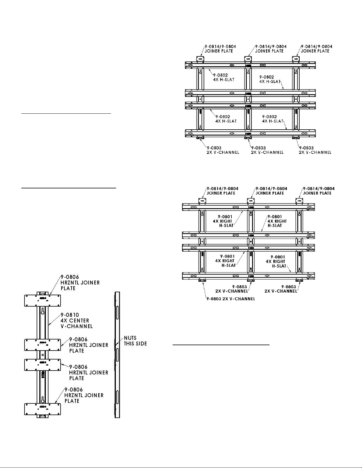
Step 3: Assemble Bottom Left Frame:
Place all of the parts in figure 1C on the floor. Start with
three 9-0803 V-channels with their open side facing up with
the narrow part of the key holes slots facing up and all in the
same direction. Place four 9-0802 Left H-Slats over the Vchannels with the keyhole surface facing up and the four-hole
patterns lining up with that of the channels. Place three 90814/9-0804 vertical joiner plates at the top of the V-channel
as shown in Figure 1C. Rectangular slots in the ends of the
slats should be at the outer edge of the frame. (See figure
3).
Bottom Left Frame (Figure 1C)
Bottom Right Frame (Figure 1D)
Step 4: Assemble Bottom Right Frame
Place all of the parts in figure 1D on the floor. Start with three 9-0803
2X V-channels with their open side facing up with the narrow part of the
key holes slots facing up and all in the same direction. Place four 90801 Right H-slat over the V-channel with the horizontal keyholes
facing up. Place three 9-0814/9-0804 vertical joiner plates at the top of
the V-channels (Figure 1D). Rectangular slots in the ends of the slats
should be at the outer edge of the frame. (See figure 3).
Figure 1E (Center Joiner Assembly)
© 2011 Adaptive Technologies Group, Signal Hill, CA 90755 USA (562) 424-1100 Rev.00-120712
Page 3

Step 5: Assemble Center Joiner Assemblies:
Place one 9-0810 center joiner v-channels on the floor, each with their
opening facing up and with the narrow end of the keyhole slots facing
up. Place four each 9-0806 Horizontal Joiner plates thread side down
over the two 9-0810 center v-channels as in Figure 1E and 2.
Step 6: Install Locking Arm brackets
Assemble the 9-0812 locking arm bracket on four of the 9-0802 left Hslat and four on the 9-0801 right H-slat near the rectangular slot using
the provided M4 screws, nylon washer and nylock nut (Figure 4). The
locking arm brackets must be installed on the first, third, fifth and
seventh horizontal H-slats starting from the top. Make sure the hook of
the locking arm bracket faces up (Figure 4 & 5). Tighten screw to
increase locking arm friction.
Figure 2
Step 7: Assemble the Four Sections of the Frame
Assemble the top left frame by attaching the horizontal H-slats,
(9-0802 , 9-0801) to the V-channels (9-0803) using the
provided M6x20mm long flat head screws. Do not tighten
screws until all screws are installed. Check for squareness by
measuring corners to corners then tighten screws starting with
the screws on the holes of the H-slats (Figure 6)
Repeat step 4 for assembling the top right frame, lower left
frame and lower right frame (Figure 6).
Step 8:
Join the top left frame and the top right frame together using
the 9-0806 horizontal joiner plate and 9-0810 4Xcenter joiner
Figure 3
V-Channels (Figure 7 & 2). Tighten screws permanently.
Step 9:
Assemble the bottom left frame and the bottom right frame
together using the 9-0806 horizontal joiner plate and 9-0810 4X
center joiner V-channels (Figure 8 & 2). Tighten screws
permanently.
Step 10:
For wall installation, refer to product installation guide.
Figure 4
© 2011 Adaptive Technologies Group, Signal Hill, CA 90755 USA (562) 424-1100 Rev.00-120712
Page 4

Figure 5
Figure 6
© 2011 Adaptive Technologies Group, Signal Hill, CA 90755 USA (562) 424-1100 Rev.00-120712
Page 5

(
)
Figure 7 (Upper/Top Frame)
Figure 8
© 2011 Adaptive Technologies Group, Signal Hill, CA 90755 USA (562) 424-1100 Rev.00-120712
Lower/Bottom Frame
 Loading...