

Page 1
HoverTrack® Series 2X2-X551-VWD
2 wide x 2 deep Video Wall Display Installation Guide
This display kit mounts NEC X551UN LCD monitors in
a 2 wide by 2 deep landscape configuration. The frame
attaches to a wall and receives the LCD monitors by
way of four machined fittings (per monitor) that thread
into the monitor’s VESA holes. These fittings then
insert into the frame’s channels. The monitor’s fittings
secure to the frame with locking arms that provide an
easy way to remove the monitors for service. A
removable panel provides access for media players
behind the frame.
Important: Installing video displays is a serious
endeavor that requires experienced professionals.
Improperly prepared walls and other structures as
well as the equipment being installed can result in
property damage, injury and/or liability to the
installing contractor. Do not proceed if any part of
the installation is in doubt.
Caution: Due to the wide variety of structures,
environments, materials and installation methods, the
installing contractor must exercise good judgment in
selecting the proper mounting area. The mounting
structure must be capable of supporting at least 5
times the load of the installed equipment. Consult local
building codes for further guidance.
Follow these instructions for the most efficient
and safest mounting results.
Package Contents:
1 pc 2x2 Frame w/ locking arms bracket
16 pcs Phillips flat head screw, M6-25mm long
16 pcs Upper-lower stand-off button (black)
16 pcs Nylon washer spacers, .28IDx .74OD, white
1 pc Instruction sheet
Notes:
Hardware to mount frame to the wall are not included
Recommended:
Install at least 3 /4” thick plywood to achieve flatness of the wall for installation and to provide an adequate support for the video display.
Note:
The assembled 2x2 frame weighs approximately 80 lb/36.4 Kg and requires at least two installers during lifting.
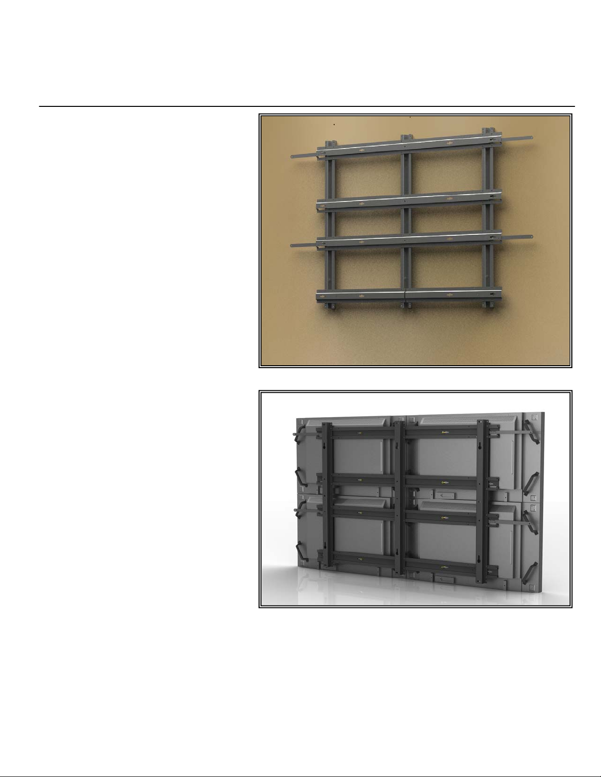
2 Wide x 2 Deep Video Wall Display (Surface Mounted)
2 Wide x 2 Deep Video Wall Display (Rear View)
© 2011 Adaptive Technologies Group, Signal Hill, CA 90755 USA (562) 424-1100 Rev.01-08/11
Page 2
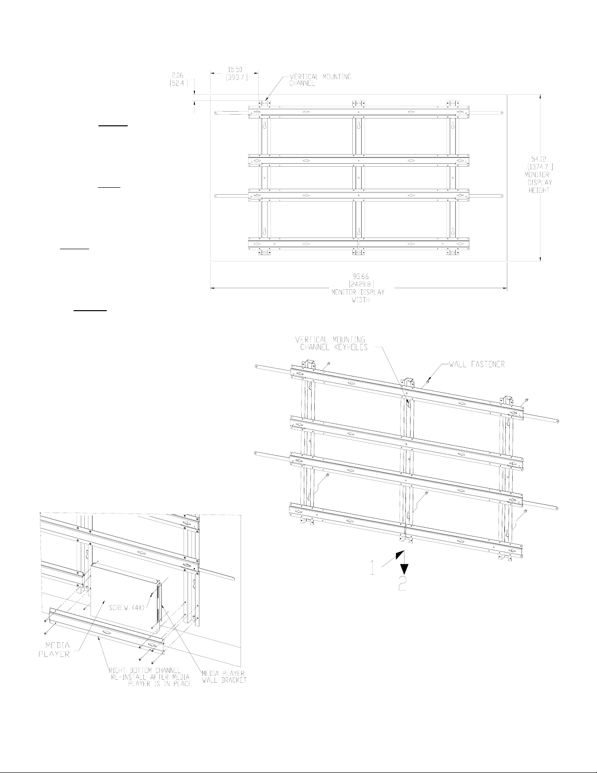
Step 1: Mount Frame to
Wall
Scribe a horizontal line on the
wall showing the exact
location of where the top edge
of the upper left monitor
will
be. Measure down 2.1”
(53.34mm) from that line and
scribe another horizontal line
showing where the top edge
of the mounting frame
will be
(Figure 1).
Scribe a vertical line showing
where the left side of the
upper monitor
will be.
Measure to the right and
scribe another vertical line
15.5” (393.6mm) to locate the
left edge of the vertical
mounting channel
(Figure 1).
Using a level, place the frame
up to the vertical and horizontal mounting frame
scribe lines. Use the frame as a template to mark
the six primary mounting key-holes.
Place the frame back on the floor and install wall
fasteners, leaving at least ¼” (7mm) of the bolt’s
shaft exposed (Figure 2).
Replace and level the mount on the wall and install
additional wall fasteners to the top, lower
horizontal slots and the center hole of the vertical
mounting channel. Tighten wall fasteners
permanently.
Figure 1
Figure 2
Step 2: Install Media Player (Optional)
Choose and remove the bottom left or right horizontal frame
channel by unscrewing its flat head screws (Figure 3). Install the
media player to the wall between the two vertical channels using
Figure 3
the appropriate fasteners through the media player’s brackets
(Figure 3). Re-install the bottom channel.
© 2011 Adaptive Technologies Group, Signal Hill, CA 90755 USA (562) 424-1100 Rev.01-08/11
Page 3

Step 3: Install upper stand-off buttons to monitors
Thread two standoff-buttons (black) into the top VESA mounting
holes in the back of each monitor using the included M6 flat head
screws (Figure 4).
Step 4: Install lower stand-off buttons to monitors
Thread two standoff-buttons (black) into the bottom mounting holes
in the back of each monitor .Tighten permanently (Figure 4).
Important: If the pitch of the monitor needs to be adjusted, add
nylon spacers between the top (or bottom) stand-off buttons and the
monitor.
Step 5: Install Left Column Monitors
Starting with the upper left monitor, connect power and signal wires
to each monitor then align its four stand-off buttons with the four
large holes of the slots in the horizontal channels. Lift up locking
arms then slide the monitor from left to right until it stops then pull
down the locking arm to lock into place (Figure 5). Repeat step 5 for
the lower monitors.
Note on alignment:
While installing monitors, check for front and side alignment of the
monitors. The surfaces of all monitors must be aligned and flush to
Figure 4
each other. If one or more screens are tilted more
than others, remove the screen(s) and, depending
whether the monitor needs to be tilted forward or
backward, apply additional nylon washers as
necessary between the monitor and its machined
fittings buttons (Figure 5). Reinstall and recheck
surface alignments. Repeat where necessary.
Step 6: Install Right Column Monitors
Starting with the upper right monitor, connect power
and signal wires to each monitor then align its four
stand-off buttons with the four large slots in the
horizontal channels. Lift up locking arms then slide
the monitor from right to left until it stops then pull
down the locking arm to lock into place (Figure 7).
Repeat step 6 for the lower monitors. Check for front
and side alignments.
Figure 5
© 2011 Adaptive Technologies Group, Signal Hill, CA 90755 USA (562) 424-1100 Rev.01-08/11
Page 4

Servicing Tips
Right Column Monitor Removal:
Reach fingers between the wall and the right monitor
and lift the locking arm (Figure 7). Slide and pull
monitor to the right (about 3/4” ) until its button fittings
disengage from the frame, then remove.
Left Column Monitor Removal:
Reach fingers between the wall and the left monitor
and lift the locking arm. Slide and pull monitor to the
left (about 3/4”) until its button fittings disengage from
the frame, then remove.
Figure 6
Figure 7
© 2011 Adaptive Technologies Group, Signal Hill, CA 90755 USA (562) 424-1100 Rev.01-08/11
 Loading...