

Page 1

Mobilift AX and AXR
Operation and Maintenance Manual
adaptive
ENGINEERING LTD.
419 – 34
(403) 243-9400 1-800-448-4652 Fax: (403) 243-9455 [email protected]
th
Ave. S.E., Calgary, Alberta, Canada T2G 1V1
Page 2

- 1 -
Mobilift AX / AXR -
Mobile Wheelchair Lift
Horizontal bridge ramp deployment
1. WARRANTY.............................................................................................................................................................................. 2
2. CAUTIONS................................................................................................................................................................................. 3
ENERAL
G
B
RIDGE RAMP
T
OWING
C
OUNTERBALANCE GAS CYLINDERS
3. FEATURES ................................................................................................................................................................................ 4
ONVENIENCE
C
S
AFETY
4. MOBILIFT AX / AXR SPECIFICATIONS.......................................................................................................................... 5
5. OPERATING INSTRUCTION PICTOGRAMS ................................................................................................................. 6
6. OPERATION DETAILS .......................................................................................................................................................... 7
O MOVE THE LIFT
T
T
O LOAD
T
O ASSIST
OPERATION OF THE LIFT WITH THE BEECH
........................................................................................................................................................................... 3
- G
ROUND RAMP
....................................................................................................................................... 3
............................................................................................................................................................................. 3
................................................................................................................................3
................................................................................................................................................................... 4
.............................................................................................................................................................................. 4
: .......................................................................................................................................................... 7
A P
ASSENGER IN
A W
HEELCHAIR TRAVELER OFF THE AIRCRAFT
A W
HEELCHAIR ONTO THE AIRCRAFT
1900 A
ND FAIRCHILD METROLINER
:............................................................................... 9
: ........................................................................................ 12
...................................................... 13
7. GENERAL OPERATING NOTES....................................................................................................................................... 16
8. MAINTENANCE..................................................................................................................................................................... 17
ENERAL
G
T
IRES
A
DJUSTMENTS
S
PRINGS
......................................................................................................................................................................... 17
................................................................................................................................................................................ 17
................................................................................................................................................................. 18
........................................................................................................................................................................... 19
9. MOBILIFT AX / AXR COMPONENTS ............................................................................................................................. 20
OP VIEW
T
T
OP VIEW
R
EAR VIEW
D
RIVE SYSTEM
S
IDE VIEW
P
ARTS LIST
1...................................................................................................................................................................... 20
2 ..................................................................................................................................................................... 21
...................................................................................................................................................................... 22
................................................................................................................................................................ 23
........................................................................................................................................................................ 24
...................................................................................................................................................................... 24
10. SUGGESTED MINIMUM INSPECTION REPORT...................................................................................................... 26
MAXIMUM CAPACITY 600 POUNDS
READ THIS MANUAL BEFORE OPERATING OR ADJUSTING THE WHEELCHAIR LIFT
Replacement parts are available within 24 hours to most North American locations from
adaptive
Version Date October 25, 1999
ENGINEERING LTD.
419 – 34
(403) 243-9400 1-800-448-4652 Fax: (403) 243-9455 [email protected]
th
Ave. S.E., Calgary, Alberta, Canada T2G 1V1
Page 3

1. WARRANTY
Adaptive Engineering Ltd. Warrants each Mobilift AX/R to be free from manufacturing or material
defects for two years from the date the product was put into service. Damages caused by vandalism or
abuse are not covered by this warranty.
- 2 -
For assistance, parts or repair information please call 1-800-448-4652 or 1-403-243-9400.
Page 4

- 3 -
2. CAUTIONS:
General
1. It is the responsibility of operating staff to ensure that the aircraft is not damaged while the
wheelchair lift is in use.
2. All precise maneuvering (i.e. alignment with aircraft or parking) should be performed using the push
handles. Do not tow lift too close to aircraft.
3. Do not attempt to crank up the lift deck from on the lift. A lift operator on the ground is required.
4. When parked, the lift should be cabled and locked to a permanent structure if it is accessible to
vandalism or susceptible to jet blasts. (see general operating notes.)
5. The deck crank handle should always be returned to the vertical position and folded in except when
it is actually being cranked.
6. Passengers on wheelchairs must be accompanied by an attendant on the lift to stabilize the
wheelchair while the lift is raised and lowered.
7. When used with the Beech 1900 C and D models and the Fairchild Metro, a spotter must be used to
guard the propeller. The configuration of both planes requires particular care. Please refer to the
end of the Operating section for detailed instructions
Bridge Ramp - Ground Ramp
1. Do not attempt to extend or retract the ramps from on the lift deck or from inside the aircraft, this
must be done by the lift operator on the ground.
2. The bridge ramp must be supported by at least a 3” overlap with the floor of the aircraft for the entire
width of the ramp.
3. The end of the ground ramp should rest flat on the ground or it may become damaged when loading
or unloading passengers from the lift deck.
4. Close deck gate prior to elevating deck.
Towing
1. No passengers or equipment are to ride on lift while being towed.
2. Maximum towing speed is 8 km/hr (5 mph).
3. Wheels must be fully lowered prior to towing.
Counterbalance Springs and Gas Cylinders
1. A large amount of energy is stored in the springs and gas cylinders used for the deck and wheel
counterbalances (respectively). Improper servicing can result in serious injury. In all cases,
contact Adaptive Engineering Ltd. for detailed information regarding servicing of these
components.
Page 5

- 4 -
3. FEATURES
Convenience
Cranking System
The high-efficiency crank system is counter-balanced to allow two adults to be lifted to maximum
height with very little effort in less than 45 seconds.
Self-leveling Ground Contacts
Automatic self-leveling of lift on uneven ground.
Tow Bar
Tow bar with integral brake release allows towing by tarmac tractors.
Spare Tire
A spare tire is attached to the Mobilift. The “quick release” design allows a wheel to be changed in less
than 2 minutes without tools.
Safety
Outriggers
Safety features that reduce the chance of overturning should a jet blast strike the lift. The lift is
designed not to overturn in a 90 mile per hour wind.
Deck Interlock
The lift deck cannot be raised unless the outriggers are extended, and the ground ramp gate is latched.
Bridge Ramp Gate
The bridge ramp gate opens automatically when the bridge ramp is lowered onto the aircraft doorsill.
Parking Brake
Automatically prevents the lift from rolling when unattended.
Emergency Lowering Crank
The lifting mechanism of the Mobilift AX / AXR is designed to lock in place in the unlikely event of a
mechanical failure. The self-braking system can be overridden using the emergency lowering crank to
lower the deck to the ground.
Bumper Pad
Non-marking urethane bumpers cushion inadvertent contact with the aircraft reducing risk of damage.
Page 6

4. MOBILIFT AX / AXR SPECIFICATIONS
- 5 -
Model
Weight 880 lb. 920 lb.
Height 77" 114"
Width 72" 72"
Length 90" 90"
Lift platform size 15"x 60" 15"x 60"
Ground ramp length 48" (slope 1:11) 48" (slope 1:11)
Bridge ramp length 77" 77"
Maximum lifting height 73" 110"
Minimum lifting height 29" 29"
Capacity 600 lb. (tested to 3,000 lb. - certified test results available on
request)
Materials 6061 T6 aluminum space frame construction
stainless steel cables (7x19 aircraft grade)
powder coated steel
sealed ball bearings
industrial duty wheels
stainless steel fasteners and fittings
Typical deploying time under 1 minute
Typical lifting time under 45 seconds to maximum height
Minimum safety factors cables: 12.0
other load-carrying components: 4.0
Features easy set up and operation by one attendant
automatic self-leveling on uneven ground
auto fail-safe crank with 2 load-activated drum brakes
automatic parking brake to prevent rolling
interlocked outrigger/crank system
designed to withstand 90 mph jet blast
quick change spare tire
cycle counter
slip-resistant surfaces
reflective marking tape
Options shed enclosure
color of powder-coated components
Markings
canopy on AX
Service requirements minimal, can be handled by technician
Parts delivery Overnight
Patents 5,040,638 and 4,926,973 (others pending, all rights reserved)
AX AXR
Specifications subject to change without notice.
Page 7
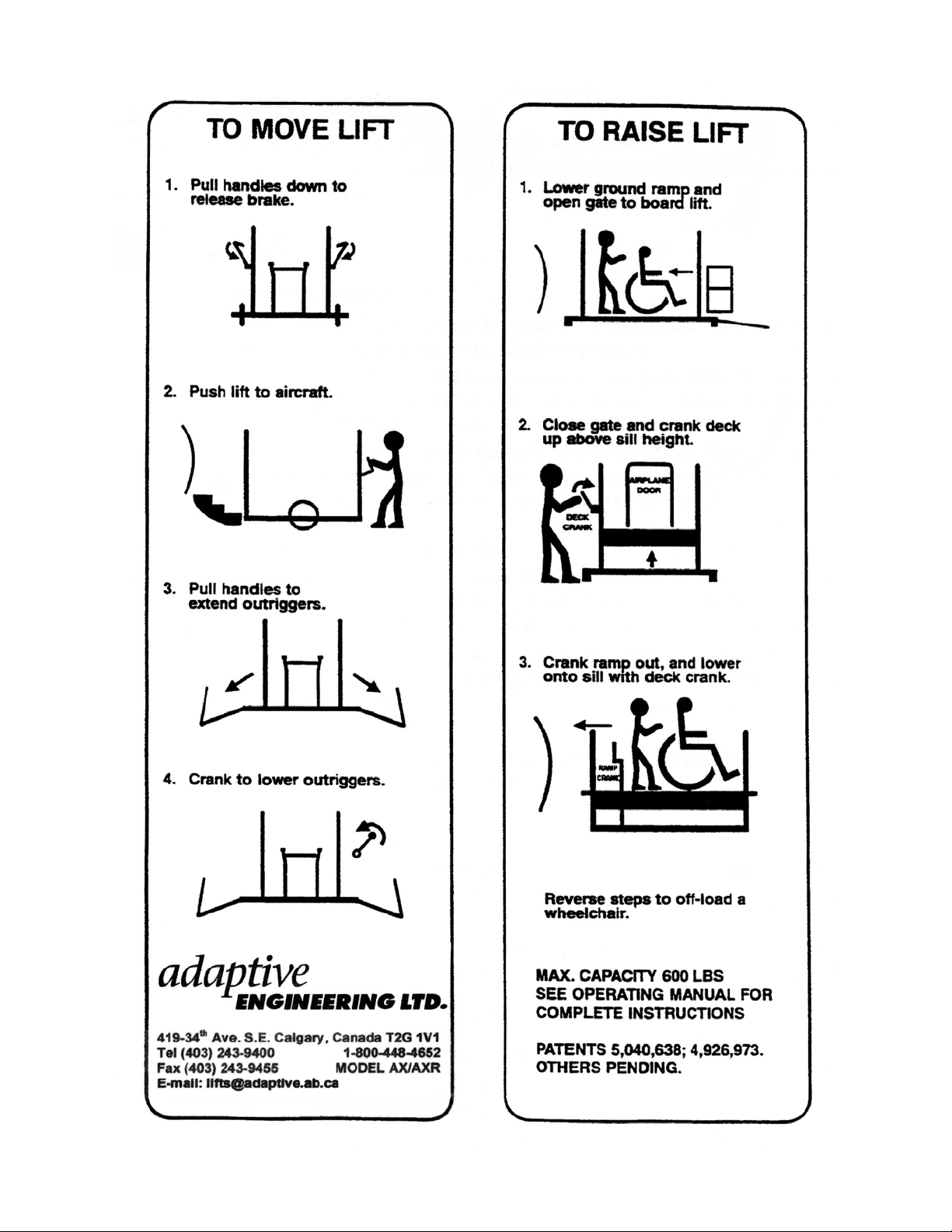
- 6 -
Page 8

- 7 -
6. OPERATION DETAILS
Bracketed numbers refer to parts that are labeled on figures in Section 8.
Operators who are using the lift with the Beech 1900 and Fairchild Metroliner, please refer to special
instructions at the end of this section.
To Move The Lift:
I. Raising Lift onto Wheels
a) The first step is to crank the lift up onto its wheels. To do this, turn the wheel crank handle
[16] clockwise until the wheels are in the full down position.
b) Visually inspect the main tires to make sure they are not under-inflated. If a tire is under-
inflated, the spare can be used or the tire can be re-inflated to the proper operating pressure.
(See Tires, in the Maintenance Section).
c) Check that the outriggers are locked in the fully retracted position. The locking handles
[42] must be engaged into the keyhole slots [43] on the positioning handles [43] to prevent
vibrations from causing the outriggers to extend while moving the lift.
II. Moving Lift Using Push Handles
a) Pull both push handles [17] down to release the automatic parking brake. The purpose of
this parking brake is to prevent the lift rolling when it is not in use. If there is any indication
that the brake is not operating properly, it must be repaired immediately.
b) To move the lift, apply a slight downward force on the push handles and push or pull as
necessary. (If the lift is being pushed on rough ground it can be quite noisy from cable
rattle. This is normal.)
IMPORTANT:
• All precise maneuvering (i.e. alignment with aircraft or parking) should be performed using
the push handles not a tractor on the tow bar.
Towing Lift Behind Vehicle
The lift can be towed behind a vehicle at a maximum speed of 8 km/hr (5 mph).
a) Lowering the tow bar [20] to attach to the towing vehicle will automatically release the
parking brake.
b) The tow bar is designed with a rubber cushioned tow ring, 17/8 inches inside diameter at a
height of 18 inches. Contact Adaptive Engineering if your towing equipment does not
match the supplied tow ring.
IMPORTANT:
• No passengers or equipment are to ride on lift while being towed.
• Maximum towing speed is 8 km/hr (5 mph).
• Wheels must be fully lowered prior to towing.
• Perform all fine maneuvering with the push handles only. Do not tow lift too close to the
aircraft.
Page 9
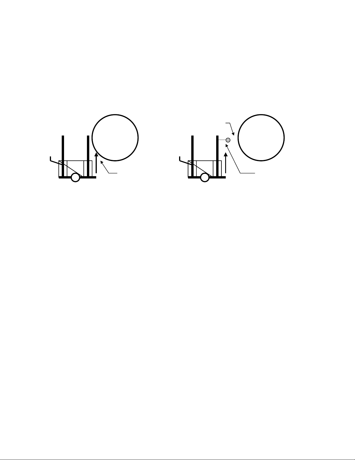
III. Aligning Lift with Aircraft
a) Carefully push the lift toward the aircraft and align the ramp with the doorway.
b) If there are stairs in place, bring the lift as close as possible to the stairs, there is a bumper
[47] on the front of the tow bar to reduce the chance of damaging the stair or lift if contact is
made.
c) If there are no stairs in place, bring the lift close to the fuselage of the aircraft using caution
not to push the end of the deck under the fuselage, see figure below. The high alignment
bumper [46] will set the minimum spacing for the Boeing 737 and MD80.
- 8 -
Up to 2’ away
Contact not necessary
d) Once the lift is in position, release the push handles allowing them to return to the upright
e) Extend the outriggers by releasing the safety locking handles and pulling the outrigger
f) Lower the lift to the ground by turning the wheel crank handle [16] counter-clockwise. Note
Cautions:
• Use extreme caution when approaching the aircraft to avoid damaging contact between the
Possible
damage when
Alignment bumper,
proper positioning
lift too close.
position automatically applying the parking brake.
handles outward to the fully extended position. As a safety feature, the lift deck cannot be
raised unless the outriggers are extended. The two outriggers on each side of the lift are
interconnected to make them move at the same time. Watch that the outriggers do not
contact the propeller, landing gear or other obstacles while extending.
that the lift is designed to rest on the two outriggers of the tow bar end, and the automatic
leveling device on the push handle end of the lift. The two outriggers on the push handle
end of the lift contact the ground but do not take load unless strong tipping forces are
applied to the lift.
lift and any part of the aircraft.
• Perform all maneuvering near the aircraft with the push handles only. Do not tow the lift
directly up to the aircraft.
Page 10

IV. Stowing the Lift
a) Park the wheelchair lift away from the aircraft with the wheels up, or in an enclosure, so
there is no possibility of it causing damage to aircraft or other airport equipment.
b) If the lift could be subjected to high winds it should be fastened securely to a permanent fixture or
be stowed inside an enclosure. An optional enclosure is available from the manufacturer.
c) The Mobilift is designed for durable reliability but it could be damaged by foreign object
debris (FOD). The lift should be stored at a location to minimize this hazard.
- 9 -
To Load A Passenger In A Wheelchair Onto The Aircraft:
I. Transferring a Passenger to a Boarding Chair
Consult the boarding chair manufacturer’s instructions for the proper procedures for transferring
passengers to and from the boarding chair.
II. Lowering the Ground Ramp and Opening the Deck Gate
Release the ground ramp [12] by unlatching the blue handgrip from its keyhole. Pivot the
ground ramp down to ground level.
Open the deck gate [44] by unlatching the deck gate latch [45] on the lifting crank side of the
lift, and allow the gate to swing fully open.
IMPORTANT:
• The end of the ground ramp should rest flat on the ground or it may become damaged when
loading or unloading passengers from the lift deck.
Page 11
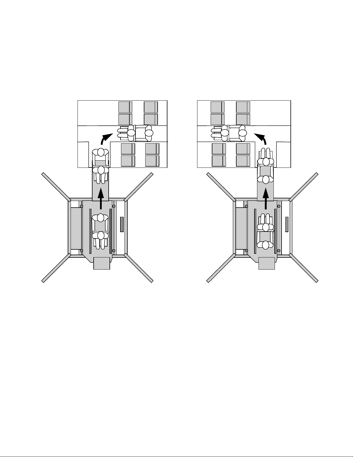
III. Positioning the Passenger and Attendant on Lift
The fore and aft location of the aircraft entrance will determine whether the passenger should be
loaded onto the lift facing towards or away from the aircraft. If the entrance door is forward of
the passenger seating, the passenger should be backed onto the lift facing away from the
aircraft. If the entrance door is aft of the passenger seating, the passenger should be loaded onto
the lift facing towards the aircraft.
- 10 -
SAAB 340, Dash 8, Beech 1900, etc. ATR 42, Jetstream 31, 32, etc.
When the passenger and attendant are positioned properly on the deck with the wheelchair
brakes locked, the deck gate [44] is then closed and relatched. The passenger should keep their
arms on their laps in front of them to avoid interference with the bracing members of the ramps.
The ground ramp remains in the lowered position until the entire loading or unloading process
is complete.
People with crutches or canes can also use the lift. They should stabilize themselves with the
deck handrails while the deck is raised and lowered.
IMPORTANT:
• Passengers on wheelchairs must be accompanied by an attendant on the lift to stabilize the
wheelchair while the lift is raised and lowered.
• It is the responsibility of the operator to determine whether other non-wheelchair passengers
require an attendant while on the lift.
Page 12

IV. Raising the Lift
To raise the deck, pull the deck crank handle [15] out and turn it clockwise until the deck is 2 or
3 inches above the sill of the aircraft door. (Note: When the deck height and lift position for a
particular aircraft is established, the operator may mark the deck height on the lift post for future
convenience.)
IMPORTANT:
• Watch to ensure that the deck and its attachments do not contact the aircraft when raising or
lowering the deck.
• The deck crank should always be returned to the vertical position and folded in except when
it is actually being cranked.
• While cranking, keep a slight outward pull on the handle to prevent it folding in.
• Do not attempt to crank up the lift deck from on the lift. A lift operator on the ground is
required.
• The lift may squeak under normal operating conditions. Please refer to the Maintenance
section for lubrication information.
- 11 -
V. Extending the Bridge Ramp
With the deck set 2 or 3 inches above the sill of the aircraft door, the bridge ramp [13] can be
extended into the doorway by pulling down and turning the bridge ramp extension crank [19]
counterclockwise. Exercise caution while extending the ramp that it is properly aligned with the
doorway and no part of the ramp contacts the aircraft. The bridge ramp has sideways float
allowing precise sideways positioning of the bridge ramp while extending. Several inches of
sideways float allows the attendant to center the ramp within the doorway by pushing or pulling
on the side of the ramp.
Ensure that the end of the bridge ramp is extended so that it overlaps the sill by at least 3" for
the entire width of the ramp.
When the bridge ramp is in position, the deck must be lowered (turning the lifting crank [15]
counter-clockwise) so that the end of the bridge ramp rests securely on the doorway sill. When
in position, the bridge ramp gate [52] will automatically be fully open.
Cautions
• Make sure the bridge ramp is properly aligned with the doorway. Extending the ramp into
the side of the aircraft can cause damage to the aircraft.
• The entire width of the bridge ramp must overlap the doorway sill by at least 3".
• Do not attempt to extend or retract the bridge ramp from on the lift deck, this must be done
by the operator on the ground.
• If the bridge ramp gate does not automatically fully open, re-check the ramp overlap and
deck height.
• The AX lift can be used to transfer passengers to aircraft floor heights of between 29” and
73”. The AXR can access aircraft floor heights of between 29” and 110”.
Page 13

- 12 -
VI. Transferring the Passenger to the Aircraft
With the bridge ramp in proper position, the attendant on the lift can move the passenger across
the ramp and into the aircraft.
VII. Retracting the Bridge Ramp
With the passenger and attendant fully inside the aircraft and clear of the bridge ramp, the
operator raises the deck 2 or 3 inches then fully retracts the bridge ramp by pulling down and
turning the bridge ramp extension crank clockwise.
IMPORTANT:
• Do not attempt to crank up the lift deck from on the lift. A lift operator on the ground is
required.
• The bridge ramp must be fully retracted to prevent interference with bracing members when
lowering deck.
VIII. Lowering the Deck
Once the bridge ramp is fully retracted, the deck can be lowered by swinging the deck crank
handle out and turn it counter-clockwise until the deck is in the full down position.
IX. Raising and Latching the Ground Ramp
When the deck is fully lowered, the ground ramp is raised and latched into place by inserting
the latch handle into the slot on the ramp.
X. Raising Lift onto Wheels
See Chapter 6, “To Move the Lift” section, Item I.
XI. Retracting and Locking Outriggers
Once the deck is lowered and the Mobilift AX / AXR is raised onto it’s wheels, the outriggers
can be retracted and locked into position with the safety handles.
XII. Releasing the Brake and Moving the Lift From Aircraft
To move the lift, pull down and apply a slight downward force on the push handles and push or
pull as necessary.
To Assist A Wheelchair Traveler Off The Aircraft:
The steps for assisting a person in a wheelchair off the aircraft are the reverse of those described above.
Page 14
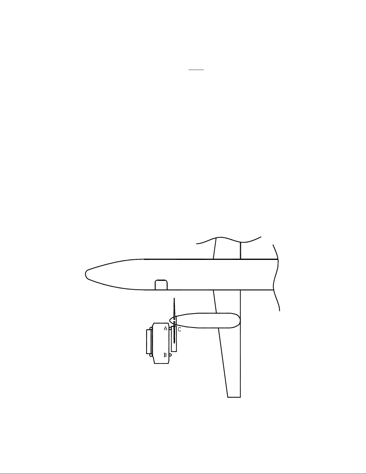
Operation of the Lift with Beech 1900 and Fairchild Metroliner
- 13 -
Operators using either of these aircraft must note the following special instructions for these difficult-toaccess planes. In both cases, an experienced spotter must
be positioned at the propeller to protect it,
because of the proximity of the spinner tip to the airplane door.
Beech 1900
1. The Mobilift should be moved towards the aircraft in line with the door, and stopped when lift post
A is 10 to 12 inches away from the spinner tip.
2. Spinner must not project inside of a line drawn from lift post A to lift post B. (If it does, it could be
damaged by the handrail as the lift is raised.) See drawing below.
3. The bridge ramp will extend to cover the distance to the sill. When deploying the bridge ramp,
bring it in above the support arms for the door cables until it sufficiently overlaps the sill and then
lower it down. The spotter must watch ramp, spinner and air stair cables during this process. The
cables may be need to be held apart to allow the ramp to pass. Reverse this step by raising the ramp
up clear of the support arms before retracting it.
Page 15

- 14 -
Fairchild Metro
With the Metro proceed as follows, referring to diagrams at the end of these instructions:
1. Station an experienced person at the propeller to be sure the lift does not touch the blades or
spinner.
2. The purpose is to get the lift pointing at the door, but sitting at an angle of about 10o . In order
to do this, lift post A must be about a foot ahead of the spinner tip - that is between the spinner
and the plane.
3. One blade of the propeller should be set at 5 o'clock (when facing the spinner) to allow the right
shroud to sit between the blades once the lift is in position.
4. The lift is brought to the plane door on a curve around the spinner. See the path of movement in
the diagram. Do not contact the spinner with the lift post A. The shroud point C will clear the
outside propeller blade by about 3 inches as it moves past. As the lift is being moved, watch
the blades to avoid contact with the shroud on the right side of the lift. The shroud will sit
exactly between the two propeller blades when the lift is in position.
5. The spinner must not project inside a line drawn from lift post A to lift post B. (If it projects in,
it will be hit by the deck handrail when the lift is being raised, which could seriously damage the
spinner.)
6. The lift is now ready for use with a wheelchair and can be operated as described in the manual.
7. Note that the guard person remains at the propeller through the entire process to ensure that the
lift does not contact the plane while the deck and ramp are moving.
8. The bridge ramp will go into the door on an angle (the ramp moves side to side to allow this).
The spotter should watch and help guide it into place if necessary. Watch the ramp handrails,
not just the ramp end. Remember to get 3 full inches of overlap onto the sill. It may be
necessary to hold the air stair cables apart to allow the ramp to pass.
9. Use the same path of travel when moving the lift away from the plane - again guarding the
spinner and propeller.
10. It is strongly recommended that the operator take time to practice this before doing it with the
additional pressure of a short turn time and a passenger waiting.
Page 16
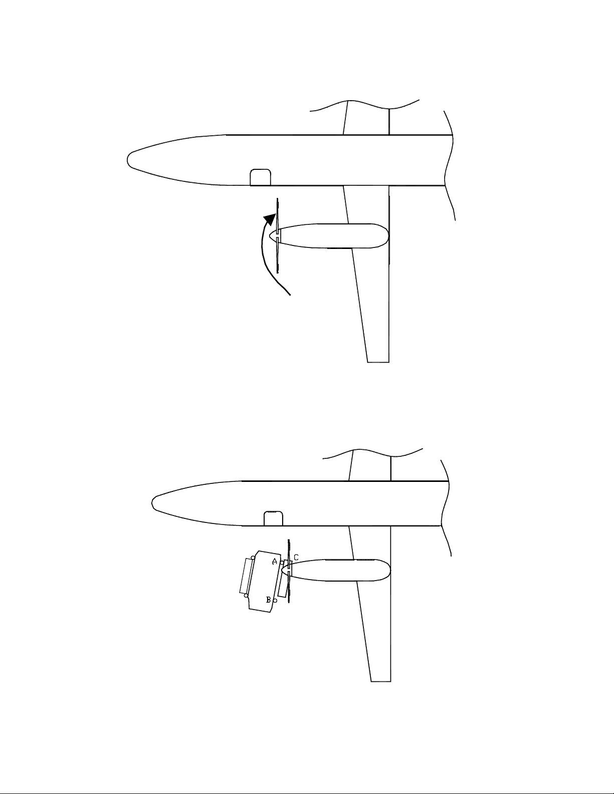
Fairchild Metroliner
- 15 -
Path of travel follows lift post A
Mobilift positioned for use
8. GENERAL OPERATING NOTES:
Page 17

a) When cranking the lift, the operator should maintain a slight outward pull on the crank handle. This
ensures the handle does not tend to fold while cranking.
b) When cranking the lift up, the more weight there is on it, the harder it will be to crank. Cranking
the deck down will feel about the same as cranking up because of the patented load activated
braking system. The brakes are actually applied by the load on the deck, so increased load on the
deck makes it harder to crank down. This is an essential safety feature of the drive system.
c) The braking system is very reliable, but additional safety is provided by folding the hand crank,
which locks the drive mechanism. This is why the hand crank must always be folded when the lift
is not actually being cranked.
d) All of the controls on the lift were designed for simplicity, reliability, and ease of use by an operator
wearing heavy mitts in cold weather. Critical components of the lift have been tested to -60 degrees
Fahrenheit.
e) Persons in wheelchairs must feel safe when being lifted. Adaptive Engineering wheelchair lifts
have an established reputation for reliability and safety. If the disabled traveler appears uncertain,
the operator should assure them that each and every lift is load tested to over 3,000 lb. before it is
placed in service. (This is about the weight of a mid-size car.) Also, there is no single component
in the lift that can allow the deck to drop in the event of failure. The lift is designed, built and tested
according to regulations governing devices that lift people.
- 16 -
Page 18

- 17 -
7. MAINTENANCE
The wheelchair lift is safety equipment. It must be inspected officially at least once a year, or in high
use areas, after every 500 uses. In addition, the day-to-day operator of the lift should make a habit of
glancing at the main lifting cables on the left side of the lift for any sign of wear or damage.
As with any piece of safety equipment, the Mobilift AX / AXR must be on a documented preventive
maintenance program. A suggested inspection report form is included at the end of this manual, airlines
and airports with an established preventive maintenance system can incorporate these requirements as
necessary.
The lift is designed and manufactured to minimize maintenance work. All exposed materials are
aluminum, stainless steel, polymers, powder-coated or electroplated steel.
Cleaning
Sand and other debris may build up on the deck of the Mobilift and affect the bridge ramp operation. It
is recommended that the aluminum deck of the unit be cleaned with pressurized air or water on a
regular basis.
Lubrication
If you experience operating squeak while raising or lowering the deck,WD40 or LPS can be used on the
deck roller guides (75). This squeak is normal and is not a safety or operational concern.
The inside of the bridge ramp drive capstan (51) may also be lubricated if necessary. There are no other
lubrication points on the lift. Wheel bearings are sealed and do not require lubricant.
The brakes may also squeal occasionally as the lift is being cranked, in the same way that automobile
brakes squeal. This is normal, and UNDER NO CIRCUMSTANCES should these brakes be cleaned
with solvents nor should they be lubricated with products such as WD40, LPS, Crown or silicon. Do
not use any lubricants under either shroud.
The serial numbers for the lifts are on the lower left rear of the lift. This serial number should be used
in recording all maintenance inspection and work. It must also be given when ordering parts.
The lift counter reading must be recorded for any inspection or maintenance work. The counter can be
viewed through a hole in the side of the counterbalance shroud, which is on the same side of the lift as
the wheel crank. For the number of uses, divide the cycle counter reading by 5.
General
The Mobilift AX / AXR is intentionally designed with open accessible parts and simple mechanisms.
Adjustments and replacements can be made by any experienced mechanic using standard tools and due
care. If uncertainties do occur, contact Adaptive Engineering Ltd. for assistance.
Tires
I. Tire Pressure
Regularly check that the tires are inflated to a pressure of 200 kPa (30 p.s.i.).
Page 19

- 18 -
II. Wheel Bearings
Wheel bearings are sealed and do not require any lubrication
III. Spare Tire
In the event that the spare tire is required, the following procedure should be followed.
a) Crank the lift down off of its wheels. Continue cranking until the tires are clear of the ground.
b) The spare tire can be removed from its mount by removing the retaining pin and sliding it
off of the mounting axle.
c) Disengage the parking brake on the tire being changed by pulling down on the push handle.
d) Remove the retaining pin and extract the axle from the tire to be changed. Remove the tire
and replace it with the spare tire. Reinsert the axle and retaining pin.
e) Have the tire serviced immediately and reinstall on the lift so that a spare tire is available.
IV. Tire Replacement
Should the tires become excessively worn or weathered, replacement tires (size 4.80/4.00-8 or
K-301M-023) can be obtained from any tire supplier. It is recommended that a tube be used
even with tubeless tires for additional reliability. The Mobilift AX / AXR is delivered with
special valve stem caps that provide additional sealing reliability. These should be replaced
with any new tires.
Adjustments
The adjustments covered in this section refer only to those items where parts are not required. If new
parts are to be installed, the parts will be supplied by the manufacturer with detailed instructions on
installation and adjustment. If the lift has been vandalized or damaged such that welding or machining
is required, it must be carried out by qualified trades people, who should also refer to the manufacturer's
literature and discuss the repairs with the manufacturer.
I. Lifting/Return Cables
As illustrated, the lifting cables [22] go from the main winding drum [32] up through the top of
the drive shroud over the upper lift pulleys [39], then down under the deck. These four cables
are critical because each supports 1/4 the load of the lift. If the inspection indicates need for
adjustment, contact the manufacturer for detailed instructions.
II. Deck Paralleling Cable Adjustments
If the inspection indicates that the deck is not level or that the paralleling cables require
adjustment, contact the manufacturer for detailed instructions.
III. Parking Brakes
The parking brakes are an important safety feature of the lift. They hold in the "off" position to
move the lift, when the push handles are released the brakes apply automatically. The brakes
can also be released by pulling down the tow bar [20].
Adjust the brake cables so that they are tight enough to pull the brake cylinder clear of the tire
but are slack when the push handles and the tow bar are in the upper (braking) position.
If the brakes do not release, or drag when the push handles or tow bar are down, the cables
Page 20

require tightening. Since the brake can be released with either the tow bar or push handles, both
systems should be checked. Adjust each brake release system individually (4 cables overall).
Retighten all cable adjustment locking nuts.
If the brakes do not provide sufficient braking force when the push handles and tow bar are
released, the following adjustment should be performed.
a) With the tow bar and push handles released, check that both cables to each brake lever are
slack.
b) If one or more cables are still tight, check that there is no damage to the cables or the lift
that may have caused this tension. Check the routing of the cables. If no damage is present
and the routing is correct, adjust the tight cable(s) until slack. Check that the brake is still
clear of the tire when the brake is released and retighten all cable adjustment locking nuts.
- 19 -
IV. Outrigger Paralleling Cable Adjustment
The two paralleling cables on each side of the lift should be adjusted together so that the
outriggers reach the extension and retraction limits at the same time.
The cables should be adjusted to provide enough tension to stay on their sheaves but be loose
enough that they do not bind.
Be sure to retighten all cable anchor locking nuts and run the outriggers through at least one full
cycle after adjustment to check function.
Springs
Two springs are used to counterbalance the load of the deck platform. These components are designed
to provide trouble-free operation and long life. Should a spring break, the deck crank will become
difficult to operate, but the lift does not have to be taken out of service. Since the spring systems can
store large amounts of energy, improper servicing can result in serious bodily injury. In all cases,
contact Adaptive Engineering for replacement parts and procedures.
Gas Cylinders
Gas cylinders (also known as gas springs) are used to assist with raising the lift onto its wheels. If the
cranking force to raise the lift onto its wheels becomes too high one or more of the gas cylinders may
need replacing. Since gas cylinders can store large amounts of energy, improper servicing can
result in serious bodily injury. In all cases, contact Adaptive Engineering for replacement parts and
procedures.
IMPORTANT:
• Do not attempt to replace or adjust the steel springs or gas cylinders without complete and
proper instructions from Adaptive Engineering Ltd.
Page 21
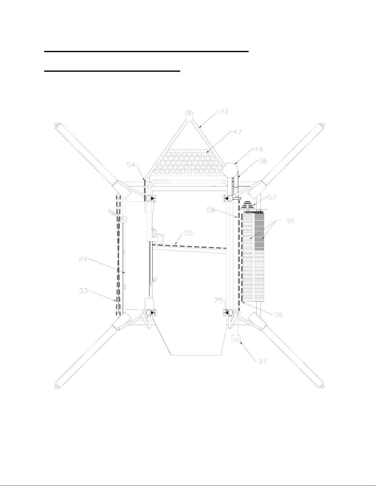
- 20 -
9. MOBILIFT AX / AXR COMPONENTS
Top View 1 (Deck not shown)
Page 22
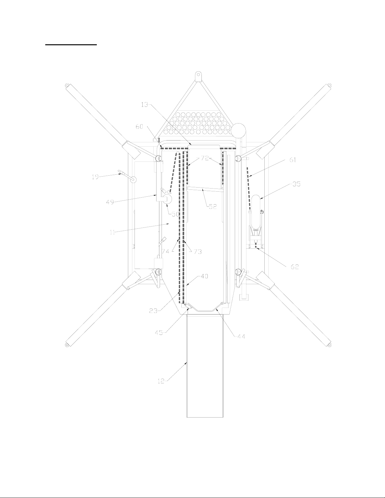
Top View 2
- 21 -
Page 23
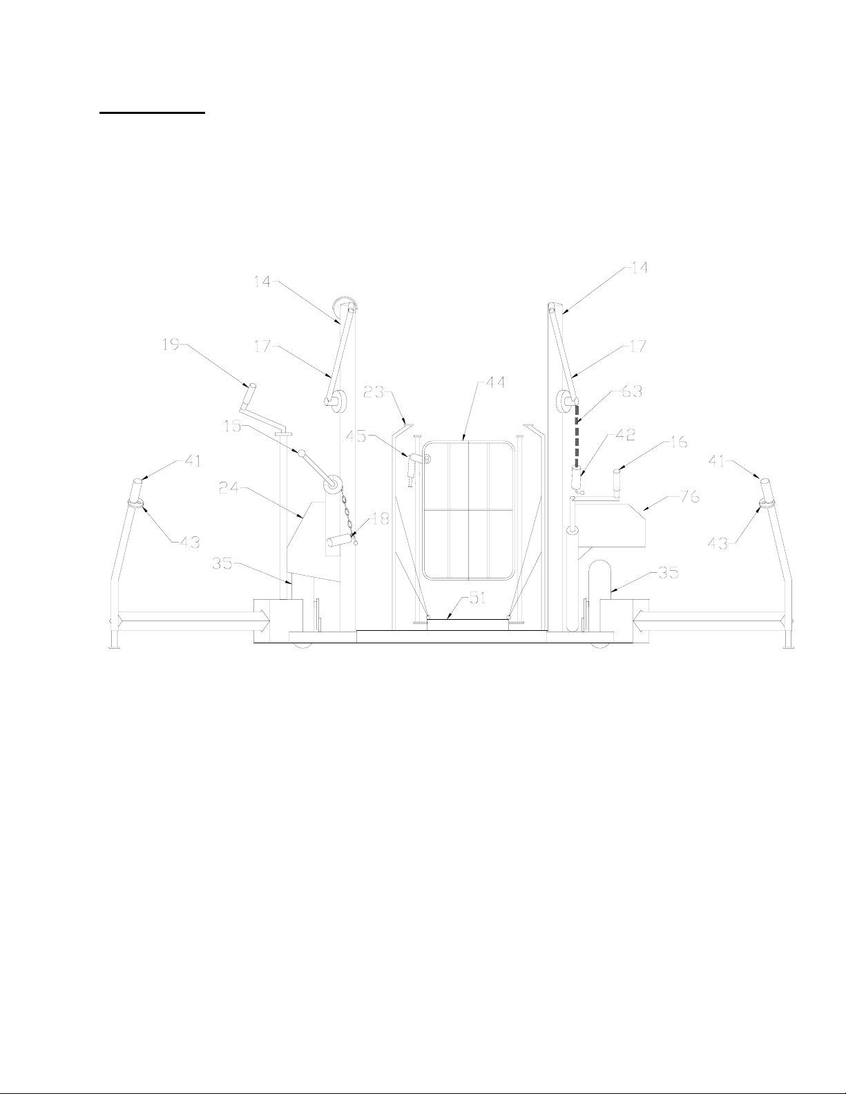
Rear View
- 22 -
Page 24
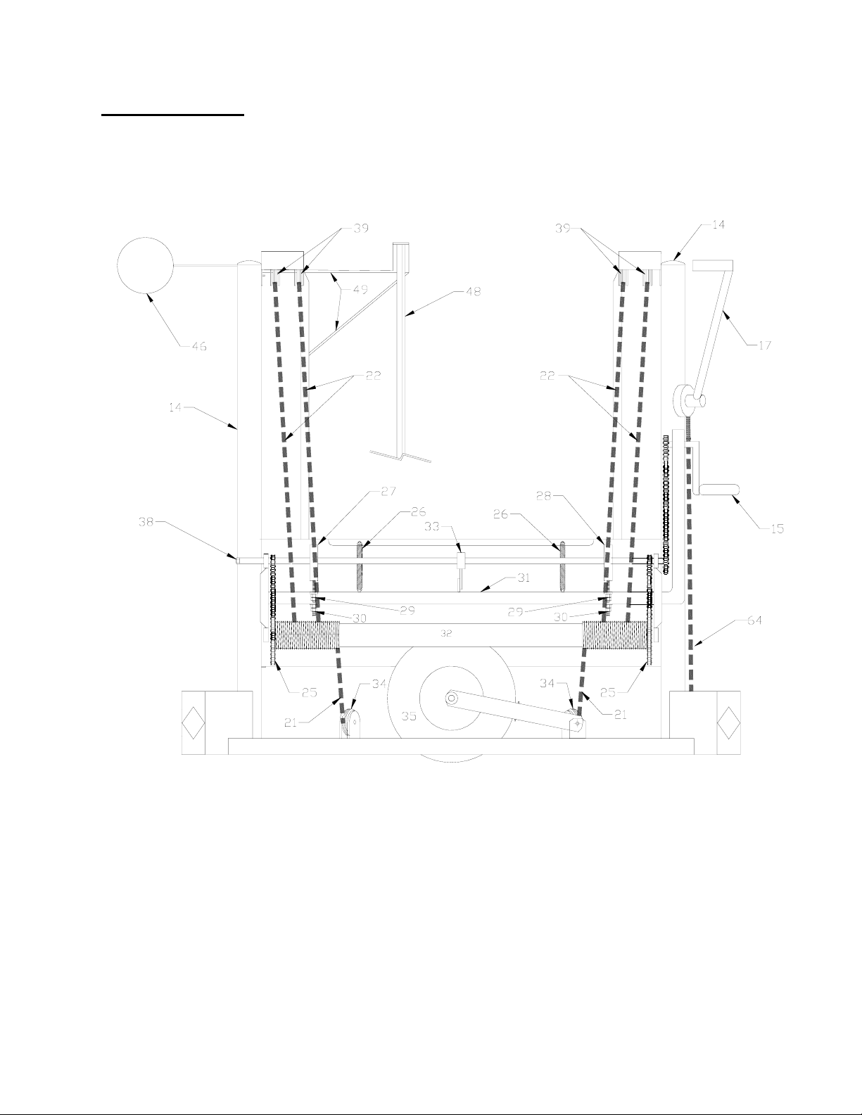
Drive System
- 23 -
Page 25
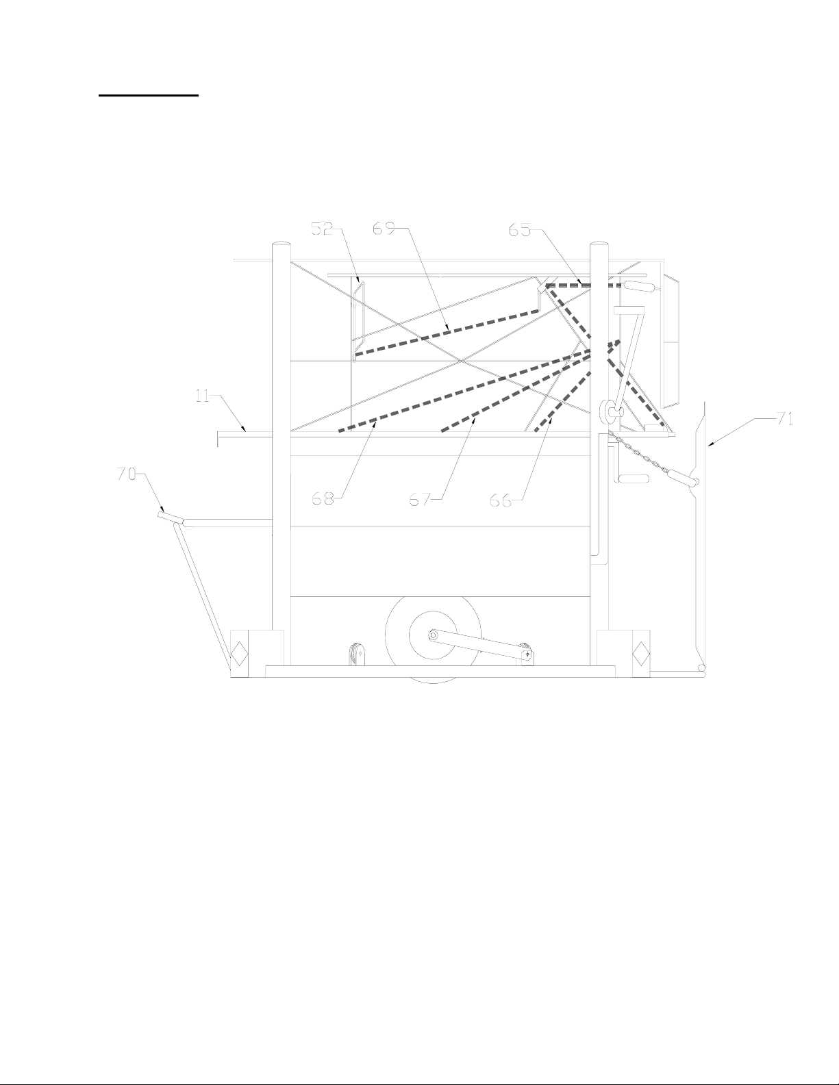
Side View
- 24 -
Page 26

Parts List
11.Main Deck
12.Ground Ramp
13.Bridge Ramp
14.Corner Post
15.Deck Crank Handle
16.Wheel Crank Handle
17.Push Handle
18.Ground Ramp Release Handle
19.Bridge Ramp Extension Crank
20.Tow Bar
21.Return Cable
22.Lifting Cable
23.Deck Handrail
24.Drive Shroud
25.Drive Chain
26.Balance Spring
27.Front Lift Brake
28.Rear Lift Brake
29.Brake Adjuster
30.Frame Adjuster
31.Drive Frame
32.Main Cable Drum
33.Steady Bearing
34.Return Pulley
35.Main Travel Wheels
36.Idler Wheel
37.Idler Caster, pivoting
38.Lift crank over-ride
39.Lift Pulley
40.Bridge Ramp Handrail
41.Outrigger Handles
42.Outrigger Retaining Handles
43.Outrigger Retaining Keyhole
- 25 -
44. Deck Gate
45. Deck Gate Latch
46. High Alignment Bumper (AXR only)
47. Bumper Pad
48. Bridge Ramp Drive Shaft
49. Bridge Ramp Drive Shaft Support
50. Bridge Ramp Drive Capstan
51. Chair Deck
52. Bridge Ramp Gate
53. Outrigger Cable
54. Tow Bar to Brakes Cable
55. Main Wheel to Wheel Connector Cable
56. Wheel Counterbalance Cable
57. Deck Counterbalance Cable
58. Thruster to Rear Wheel Cable
59. Counterbalance Springs
60. Paralleling Cable
61. Thruster to Front Wheel Cable
62. Brake Plunger Cable
63. Outrigger Restraints Cable
64. Brake Handles to Brake Cable
65. Bridge Ramp Z Cable
66. Rear Chair Deck Suspension Cable (short)
67. Middle Chair Deck Suspension Cable (med)
68. Front Chair Deck Suspension Cable (long)
69. Bridge Ramp Gate Activation Cable
70. Tow Hitch
71. Ground Ramp
72. Bridge Ramp Centering Cable
73. Bridge Ramp to Capstan Cable (Rear-Adjust)
74. Bridge Ramp to Capstan Cable (Front-Fixed)
75. Deck Roller Guides
76. Counterbalance Shroud
Page 27

10. SUGGESTED MINIMUM INSPECTION REPORT
Mobilift AX / AXR Wheelchair Lift, (Minimum inspection once per year)
1. Perform a complete general visual inspection for loose fasteners and for damaged or missing components.
2. With the deck at ground level, a 10 lb. (5 kg) pull on the middle of each of the outer lifting cables should separate the cables between 3-1/4 and 3-3/4 inches (8
and 10 cm) for the AX and between 3-3/4 and 4-1/4 inches (9 to 11 cm) for the AXR.
3. Check the full visible length of each lifting cable with the deck at ground level and at two feet from ground level for corrosion or fraying, with particular attention
to the point at which the cables turn in under the deck.
4. With the lift deck about half way up with no load, measure the distance from the deck to the top of the main frame at each corner. The two rear measurements
(near the ground ramp) should be within 1/2 inches (1 cm). The two front measurements (near the bridge ramp) should also be within 1/2 inches (1 cm). The front
should be 1 ±1/4 inches (2 to 3 cm) higher than the rear.
5. Check by looking under the shroud that the cables are in their grooves on the winding drum. Crank deck to full height with no deck load and recheck the cables
on the winding drum.
6. Visually inspect all threaded cable anchors (35 in total) to ensure they are secure and have properly installed lock nuts:
Frame and Wheel Anchor Points:
- 26 -
Under Main Deck Anchor Points:
Main Deck Anchor Points:
Outrigger Cables (4)
Wheel Activation Cables (located underneath the wheel crank side wheel bracket) (3)
Tow bar/Brake Handle Activation Cables (4)
Main Deck Paralleling Cables (4)
Lifting Cables (4)
Return Cables (2)
“Z” Cables (which support the Bridge Ramp when extended) (2)
Bridge Ramp Centering Cables (there are 2 cables with a total of 4 threaded anchors)
Bridge Ramp Drive Cables (2)
Chair Deck Bracing Cables (6)
7. Where possible, inspect all the non-threaded anchors for the cables listed above.
8. Check that the paralleling cables are on all four pulleys, are not frayed, and have no slack.
9. With the deck all the way down, a pull of 10lb at the mid-point of each paralleling cable should produce the following deflections for an AX lift : 1 to 1-1/2”
inches (2.5 to 4 cm) for the cables on the left (drive side) of the lift, and 1/2 to 1 inches (1 to 2.5 cm) for cables on the right (counterbalance side) of the lift. On an
AXR the deflections should be 1-1/2 to 2-1/4” (4 to 6 cm) for the left cables and 3/4 to 1-1/2” (2 to 4 cm) for the right cables.
10. Check that the paralleling cable pulleys can not scrape on the sides of the posts.
11. With the deck at ground height, check that the counter balance cable is under tension and shows no signs of fraying or damage. Repeat this test with the deck at
full height.
12. Check that the lifting crank handle and bridge ramp extension handles lock automatically when released.
13. Crank the deck to full height and back down with 400 to 500 lb. (180 to 230 kg) (three people) on the deck (a full up down cycle should take no more than one to
two minutes).
14. With the above weight on the deck and the deck approximately 36 inches (90 cm) off the ground, using a spring scale or weight, check the force on the crank
handle, the force cranking up should be between 15 and 20 lb. (7 and 9 kg). The force to crank down should be between 1/3 and 1/2 of the force to crank up.
15. Did the deck crank smoothly up and down? (On the down movement it is normal to have a slight squeal or chatter from the brakes as with automobile brakes).
16. Inspect the tires, including the spare, for damage or wear. They should have between 28 and 32 p.s.i. (190 and 220 kPa) pressure at 70°F (20°C).
17. Crank the wheels down to raise the lift off the ground. Check for full movement and smooth operation of the wheel crank mechanism.
18. With the wheels in the full down position, measure the distance from the ground to the frame next to the wheel axle on each side of the lift. These two
measurements should be within 1/2 of an inch (1.25 cm) of each other.
19. Check the action of the front and rear idler wheels. With the main travel wheels cranked fully down, the rear idler caster should be in a position to hold the lift
essentially horizontal with no part of the frame contacting the ground. The front idler wheel should prevent the frame from contacting the ground when the lift is
tipped forward, but should normally be 1/2 to 1 inch (1 to 2.5 cm) above ground height.
20. With the lift in the "travel" mode, check that the lift rolls easily with push handles down and that it stops immediately when these are released. Check that the lift
rolls easily with the tow bar pulled down to 45° and that the lift stops when the tow bar is released.
21. Check the action of the left and right outrigger pairs. The outriggers on each side should extend and retract to their limits smoothly and in unison.
Continued on next page
22. Check that the outrigger latches function properly.
.
Page 28

- 27 -
23. Check that the automatic leveller bar is free to move when the lift is on its wheels.
24. With the deck raised to approximately 36 inches (90 cm), check that the bridge ramp rolls out and returns smoothly using its crank handle. It should not be
possible for the ramp to be pushed in or out without using the crank.
25. Check that the bridge ramp centers positively and smoothly when fully extended.
26. Check that the bridge ramp centering cables are tight when the ramp is centered.
27. Extend the bridge ramp and lift upwards on the end. The bridge ramp gate should open and close fully and reliably as the end of the bridge ramp moves up and
down.
28. Check that the “Z” cables (that support the bridge ramp) hold the ramp parallel to the main deck in all positions.
29. With the bridge ramp fully retracted and one person standing on the deck (near the ground ramp), check that the chair deck bracing cables hold the deck 1/2 inch
above the bridge ramp (measure at the anchor points for the braces).
30. Test for the smooth and safe operation of the ground ramp and its latch.
31. Check that the ground ramp gate latch works and that the gate springs fully open when unlatched. With the deck at ground height the ground ramp latch should
pivot so as interfere with the deck crank when the ground ramp gate is open (this prevents the lift being raised with the ground ramp gate open).
32. Inspect the aircraft protection bumper(s) for excessive stiffness or damage. One is located on the tow bar to protect airstairs, the other is optional to protect the
fuselage.
33. Check the non-slip walking surfaces on the ramps and deck for excessive wear.
34. Record cycle counter reading. Divide by 5 for number of uses. Counter Reading ____________ # of Uses _______________
35. LOAD TEST. At the end of inspection work and any repairs or adjustments, the lift must be re-load tested to 1800 lb. (820 kg) which is three times the design
load.
36. Perform at least one full deployment/lifting cycle (from raising the lift onto its wheels through to parking after use) to test all functions of the unit. Contact
Adaptive Engineering Ltd. should any function or component be substandard.
__________________ _________________________ ___________________________________________________________
Lift Serial No. Date of Inspection Inspected By (Please Print)
____________________________________________________ ______________________________________________________________
Location Signature of Inspector
Inspector Employed By: _____________________________________________________________________________________________________
Final page of inspection report.
 Loading...