

Page 1
1
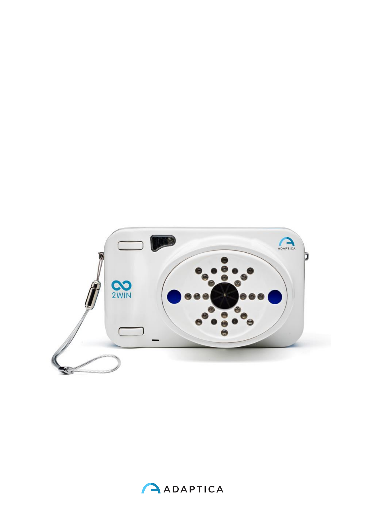
2WIN
OPERATOR MANUAL
Page 2

2
Revision notes
Software configuration version
4.2.170426
Publication date
2017/05/03
Hardware configuration version
Version 17.0 and earlier
Rev Num.
4.5
Page 3

3
1 Summary
1 SUMMARY ......................................................................................................................................................... 3
1. MANUFACTURER IDENTIFICATION .................................................................................................................... 6
2. LEGEND OF SYMBOLS ........................................................................................................................................ 6
3. GLOSSARY ......................................................................................................................................................... 7
4. INTENDED USE OF THE DEVICE .......................................................................................................................... 9
5. CLASSIFICATION AND APPLIED STANDARDS ...................................................................................................... 9
CLASSIFICATION ACCORDING MDD 93/42/EEC, ANNEX IX........................................................................................................ 9
CLASSIFICATION AND TYPE OF APPLIED PARTS ............................................................................................................................ 9
IP CLASSIFICATION ............................................................................................................................................................... 9
ELECTROMAGNETIC COMPATIBILITY ........................................................................................................................................ 9
APPLIED STANDARDS............................................................................................................................................................ 9
6. QUICK USER GUIDE ...........................................................................................................................................10
THE 2WIN ...................................................................................................................................................................... 10
MAIN APPLICATIONS .......................................................................................................................................................... 11
EXAM CONDITIONS ............................................................................................................................................................ 11
EXAM PROCEDURE ............................................................................................................................................................ 11
MEASUREMENT TIPS .......................................................................................................................................................... 13
7. DESCRIPTION OF THE DEVICE............................................................................................................................14
LABELS ............................................................................................................................................................................ 16
PACKAGE LABELING ........................................................................................................................................................... 18
INTERFACES ..................................................................................................................................................................... 19
GRAPHICAL USER INTERFACE................................................................................................................................................ 23
8. PRECAUTIONS ..................................................................................................................................................24
9. OPERATIVE INFORMATION ...............................................................................................................................26
REGISTER YOUR 2WIN ....................................................................................................................................................... 26
OPERATING CONDITIONS .................................................................................................................................................... 26
UNPACKING ..................................................................................................................................................................... 26
INSERT BATTERY ................................................................................................................................................................ 27
EXTRACT BATTERY ............................................................................................................................................................. 27
BATTERY-CHARGING .......................................................................................................................................................... 28
DATA MANAGEMENT DISCLAIMER ........................................................................................................................................ 29
A ENVIRONMENT SETUP .............................................................................................................................................. 31
B INSTRUMENT SETUP ................................................................................................................................................. 32
EYE SELECTION ................................................................................................................................................................. 32
INTERACTIVITY/ATTRACTION OF THE PATIENT .......................................................................................................................... 33
PATIENT DATA .................................................................................................................................................................. 34
BROWSING MODE ............................................................................................................................................................ 35
C PREPARATION OF THE PATIENT ................................................................................................................................... 36
Page 4
4
D MEASUREMENT ...................................................................................................................................................... 37
ZOOM FUNCTION .............................................................................................................................................................. 42
QUICK MENU ................................................................................................................................................................... 51
CONTEXTUAL HELP ............................................................................................................................................................ 52
SUMMARY OF MENU ENTRIES .............................................................................................................................................. 53
PRINT TO PORTABLE INFRARED PRINTERS................................................................................................................................ 55
MAIL PRINTING ................................................................................................................................................................ 56
SAVE EXAM ...................................................................................................................................................................... 57
HIRSCHBERG TEST ............................................................................................................................................................. 64
CUSTOMIZATION ............................................................................................................................................................... 64
NOTIFICATION CENTER ....................................................................................................................................................... 66
SCREENING MODE ............................................................................................................................................................ 66
SCREENING TABLE ............................................................................................................................................................. 67
UPLOAD .......................................................................................................................................................................... 69
PAIRING AND TRANSFERRING A 2WIN TEST TO VISIONFIT ......................................................................................................... 69
11. WIRELESS CONNECTIONS..................................................................................................................................72
WIFI CONNECTIVITY .......................................................................................................................................................... 72
SFTP E VNC + SSH ACCESS CREDENTIALS ................................................................................................................................. 75
SFTP AND VNC+SSH SUGGESTED SOFTWARES ...................................................................................................................... 76
KEYBOARD COMMAND FOR THE USE OF VNC+SSH .................................................................................................................... 76
12. APPLICATIONS (PACKAGES) ..............................................................................................................................77
INSTALLATION .................................................................................................................................................................. 77
ACTIVATION ..................................................................................................................................................................... 77
VISUALIZATION ................................................................................................................................................................. 78
AUXILIARY WINDOWS ........................................................................................................................................................ 78
MODES (2WIN APPLICATIONS) ................................................................................................................................... 78
13. SOFTWARE UPGRADE INSTRUCTIONS ..............................................................................................................79
14. MAINTENANCE AND CLEANING INSTRUCTIONS ................................................................................................80
STORAGE INSTRUCTIONS ..................................................................................................................................................... 80
INSTRUCTIONS FOR CORRECT DISPOSAL OF THE DEVICE .............................................................................................................. 80
SEPARATE COLLECTION FOR ELECTRICAL AND ELECTRONIC EQUIPMENT ......................................................................................... 80
15. 2WIN APPLICATIONS SPECIFIC MANUALS .........................................................................................................82
LEGENDS OF SYMBOL ......................................................................................................................................................... 82
2WIN APPLICATIONS INSTALLATION (THE SAME STEPS FOR EVERY APP) ....................................................................................... 82
ANALYSIS OF CORNEAL REFLEXES POSITION (CR-APP) .............................................................................................................. 83
Corneal Reflexes exam ............................................................................................................................................ 85
Exam ........................................................................................................................................................................ 85
Exam Results from ‘Corneal Reflexes’ App .............................................................................................................. 88
Print ......................................................................................................................................................................... 91
Measurement reset ................................................................................................................................................. 93
DYNAMIC PUPILLOMETRY APPLICATION.................................................................................................................................. 94
Dynamic pupillometry application activation ......................................................................................................... 95
Dynamic Pupillometry exam and modes ................................................................................................................. 96
Exam ........................................................................................................................................................................ 97
Page 5
5
Standard mode ........................................................................................................................................................ 97
Manual mode .......................................................................................................................................................... 98
Calibration mode ..................................................................................................................................................... 99
Exam display.......................................................................................................................................................... 101
Browsing mode ...................................................................................................................................................... 102
Post exam measurements ..................................................................................................................................... 103
LENS CENTERING APPLICATION (LC-APP) ............................................................................................................................ 109
Lens Centering Application activating ................................................................................................................... 109
Measurement with the App activated ................................................................................................................... 110
Activation in Browsing mode................................................................................................................................. 111
Overview ............................................................................................................................................................... 111
Navigation ............................................................................................................................................................. 113
How to position the horizontal axis ....................................................................................................................... 113
How to position the vertical axes .......................................................................................................................... 114
Centering values .................................................................................................................................................... 114
Printing on SD and creating of the report ............................................................................................................. 115
INTERMEDIATE VISION TEST .............................................................................................................................................. 117
Components .......................................................................................................................................................... 117
Intermediate Vision application activation ........................................................................................................... 118
Intermediate Vision Exam ..................................................................................................................................... 119
Environment setup ................................................................................................................................................ 120
Exam ...................................................................................................................................................................... 121
Output ................................................................................................................................................................... 123
16. TROUBLESHOOTING ....................................................................................................................................... 124
17. ADDITIONAL INFORMATION ........................................................................................................................... 125
TECHNICAL SPECIFICATION ................................................................................................................................................ 125
RECHARGEABLE BATTERY SPECIFICATIONS............................................................................................................................. 125
OTHER SPECIFICATIONS .................................................................................................................................................... 125
IN FLIGHT USE ................................................................................................................................................................. 126
DEVICE WARRANTY .......................................................................................................................................................... 126
18. ANALITIC INDEX .............................................................................................................................................. 126
19. INFORMATION FOR ASSISTANCE .................................................................................................................... 126
NOTE FOR SERVICE PERSONNEL ONLY .................................................................................................................................. 126
REMOTE CONTROL .......................................................................................................................................................... 127
TELEMETRY .................................................................................................................................................................... 127
20. APPENDIX A (DATA MANAGMENT DISCLAIMER) ............................................................................................ 128
21. APPENDIX B – HOW TO MANUALLY CONFIGURE SOME OF THE INFRARED PRINTERS ..................................... 131
PORTABLE PRINTER GEBE GPT-4378-FLASH-79-V.24-IRDA-SET ......................................................................................... 131
PORTABLE PRINTER SEIKO DPU-S_245 .............................................................................................................................. 133
Page 6
6
1. Manufacturer identification
Manufacturer
Adaptica S.r.l.
Address
Via San Marco, 9/H
35129 Padova (PD)
Italy
Telephone
+39 049 773 968
Mail:
Web:
www.adaptica.com
2. Legend of symbols
Manufacturer identification data
Date of manufacturing
Electrical / electronic device subject to the WEEE
Directive on waste disposal
CE mark: this device complies the base requirements
of the Medical Device Directive 93/42/CEE
Direct current (DC)
Warning: necessary information for safety
Important information
Page 7
7
3. Glossary
Accommodation:
The power (or ability) of the eye to alter the shape of its
lens so that it can adjust the focus of the eye for
distance and closeness.
Anisometropia
A condition in which the refractive power of the eyes
is unequal.
Astigmatism
A condition in which the optical (or outer) surfaces of
the eye are distorted so that light rays are not sharply
focused on the retina for either near or distant vision.
Auto Shutdown
A procedure whereby 2WIN stops to work and switches
off automatically.
Auxiliary window
Graphical window that displays additional data.
Binocular vision
The use of both eyes simultaneously in such a manner
that each retinal image contributes to the final percept
of a single image.
Diopter
The refractive power of a lens. It is used as a unit of
measurement in refraction.
Esophoria
A tendency for the eyes to turn inward, when fusion is
suspended.
Esotropia
Marked turning inward of the eye; crossed eyes.
Exophoria
A tendency for the eyes to turn outward, when fusion is
suspended.
Exotropia
Divergent strabismus; abnormal turning outward of one
or both eyes.
Fixation
Movement of the eyes so that the visual axes meet and
the image of an object falls on the corresponding points
of each retina.
Focal point
The point to which rays are converged after passing
through a lens.
Heterophoria
A tendency for deviation of the eyes, when fusion is
suspended.
Heterotropia
A manifest deviation of the eyes resulting from the
Page 8
8
absence of binocular equilibrium.
Hypermetropia
Hyperopia.
Hyperopia
Farsightedness is a refractive error in which the image
does not come to focus before striking the retina in the
relaxed eye. Accommodation may be used to
overcome small amounts of hyperopia.
Monocular
Involving the use of a single eye.
Myopia
Nearsightedness is a refractive error in which the point
of focus for light rays is in front of the retina, resulting in
blurred distant vision.
Occlusion
Obscuring the vision of one eye to test the vision or
force the use of the other eye.
Orthophoria
Parallelism of visual axes, the normal eye muscle
balance.
2WIN Applications
Additional software features that can be installed
directly on 2WIN.
Refraction
When referred to human eye, this term, or the term
Refractometry, are used to indicate the measurement
of the Refractive Error, that is the error in the focusing
of light by the eye.
Refractive Error
Equivalent to ametropia, it is usually decomposed into
a spherical error and a cylindrical error. Types of
ametropia include myopia, hyperopia and astigmatism.
Spherical error
Occurs when the optical power of the eye is either too
large or too small to focus light on the retina.
Strabismus
Failure of the two eyes to direct their gaze at the same
object because of inappropriate neuromuscular control
or because of fibrosis or paralysis of one or more
extraocular muscles, as in crossed eyes or walleyes.
Page 9
9
4. Intended use of the device
Instrument for the measurement of binocular and monocular refraction, dynamic
photoskiascopy.
5. Classification and Applied Standards
Classification according MDD 93/42/EEC, Annex IX
Class IIa
Classification and type of applied parts
There are no applied parts.
IP classification
IPX0 (degree of protection provided by the external plastic shells with reference to the
penetration of any special material or water).
Electromagnetic compatibility
This device has been classified as class B according to the normative IEC60601-1-2.
Applied standards
EN 60601-1; EN 60601-1-2; EN ISO 15004
Page 10
10
6. Quick user guide
Register your 2WIN: registration takes less than 1 minute!
It's highly recommended to register your 2WIN at:
http://www.adaptica.com/user-registration/
Important
• The 2WIN is a binocular refractometer and vision analyzer. It measures refraction of
both eyes at the same time, at a distance of 1 meter.
• The 2WIN should not be confused with a table-top auto-refractometer (AR). ARs
are designed to measure refractive errors of one eye at time, in an artificial
condition of far fixation. Please do not consider the 2WIN a small portable autorefractometer or two small ARs glued together!
• Working in natural binocular conditions the 2WIN allows to evaluate simultaneously
not only refractive errors, but also gaze direction, ocular alignment, pupil diameter,
pupil distance and the accommodative balance/unbalance between the 2 eyes.
Many other features can be measured by the 2WIN using optional applications
(2WIN APPs).
• Please familiarize yourself with the measurement conditions and techniques of the
2WIN in order to exploit its full potential.
The 2WIN
• The 2WIN detects a patient’s real-time refraction in the most natural environmental
conditions.
• It is a binocular instrument that measures refraction on the basis of eccentric
InfraRed photo-refraction (also photo-retinoscopy). Both eyes are measured at the
same time in free space, while fixating at 1 meter.
• It must be operated in a dim light environment to ensure sufficient pupil size and
reduce accommodation.
• It is hand-held, battery operated, very light, non-invasive, fast and easy to use.
• It automatically measures binocular refraction, pupil distance, pupil size, direction of
gaze, and fixation abnormalities.
Page 11

11
Main applications
• Refraction of infants and children from 2 months of age, seniors, impaired and noncooperative patients.
• Early detection and documentation of multiple amblyogenic factors.
• Un-aided binocular refraction of all other patients
• Over-refraction of glasses or contact lenses.
• OPTIONAL (APPs)
• Phoria/tropia measurements
• Dynamic pupil response time and size caused by artificial light created by
2WIN
• Centering of the visual axis on the glasses frame
• Addition power measurement at the 66 cm distance from the patient
Exam conditions
• The patient shall sit comfortably in a suitable exam room; infants should sit in
adult’s lap. A uniform dim light environment is necessary.
• The 2WIN accuracy is affected by external sources of light in particular HOT lights
halogen or incandescent lamps because of the presence of high infrared content of
the light; please make sure no direct light hits the patient’s face and ensure uniform
light on both eyes.
• A stable measurement distance of 1 meter is also important.
Exam procedure
• Turn the 2WIN ON by pressing the ON/OFF button for 1 sec. and wait until the
stand-by screen appears.
• Instruct the patient to keep his/her eyes wide open, clear of eyelids or eyelashes,
and to fixate the centre of the camera. Hold the 2WIN horizontally with both hands,
approximately at the same height of the patient’s eyes, and at a distance of 1 meter.
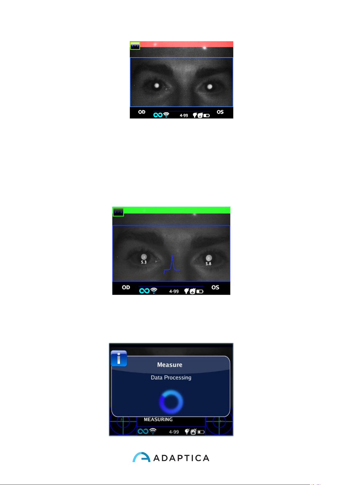
• Press and hold the START button to enter the focusing phase.
• Center the eye / eyes of the patient in the active display within the blue rectangle
(measurement area)
Page 12
12
Screen examination – blurred, not in focus. Adjust the distance from the patient
• Adjust the distance to focus the image until the top bar is green and the focusing
indicator based on corneal reflex shape appears in the centre of the screen.
• When the top bar is PERMANENTLY green and the focusing indicator (in the center
of the image) reaches the highest peak (as shown in the following photo) release
the BUTTON S1/S2.
Examination screen – focus OK
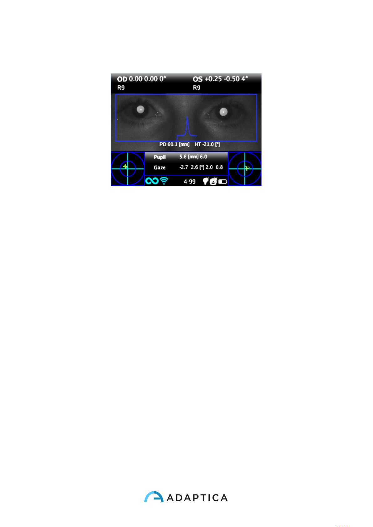
• Stay firmly in the condition in which the upper bar is green and the focusing
indicator is sharp until the message DATA PROCESSING appears on the display.
Page 13
13
Data Processing message
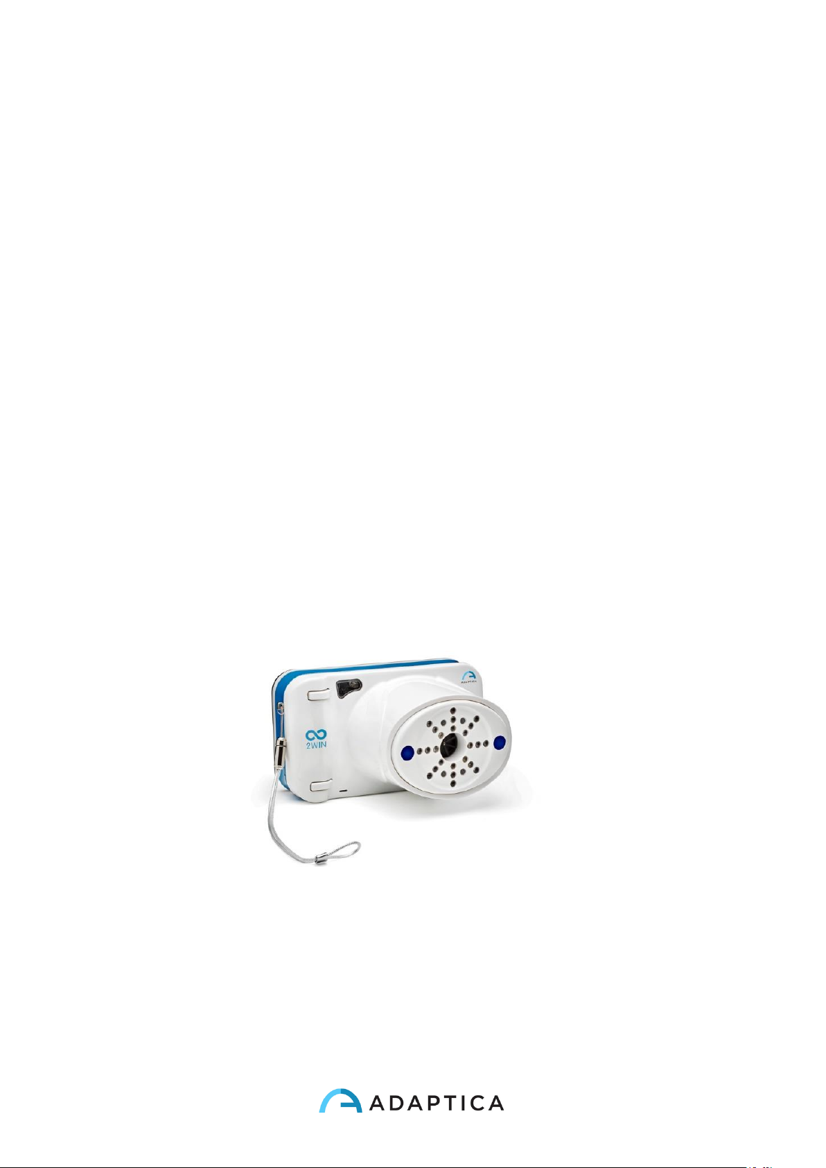
After Data Processing measurement results will be displayed.
Measurement screen
Measurement tips
• For both Sph and Cyl, measurement accuracy is ± 0.25 D in the range of ±5 D. The
cylinder axis is calculated between 1° and 180° (step 1°) with precision of ±5°. For
higher refractive errors, the 2WIN displays “high M” (myopia) or “high H”
(hyperopia). In the case the 2WIN displays “high M” or “high H” without displaying a
numerical result, 2WIN will write in the upper part of the display “n.a.” (not accessed
measurement). For big refractive errors, in the case 2WIN succeeds to estimate the
spherical power only, this estimation will appear in the upper part of the display.
This maximum spherical estimation is 15D.
• Make sure the cylinder notation (minus or plus) is set to your preference.
• During the measurement mode, please make sure that both eyes appear within the
Graphical User Interface paragraph; if necessary, slightly tilt the 2WIN.
• If you wish to refract infants, young children and any non-cooperative patients, you
can turn the audible and/or the visible fixation targets ON. Audio fixation (attraction
system) is preferable to the visible small lights fixation.
• Make sure the Reliability Index of the refraction measurement is higher than 5 (max.
is 9). In case of Reliability Index of 5 or less a message with a hint will be displayed.
Please repeat the measurement, if possible.
• Over-refraction with contact lenses is as easy and accurate as without correction.
• For accurate over-refraction with glasses, please make sure that no stray light
reflexes disturb the pupil detection; should such reflexes be present, please slightly
tilt the glasses down.
• Please remember that free space, non-cycloplegic refraction can vary depending on
several conditions and parameters pertaining to the binocular visual function; in
Page 14
14
some specific patients, including accommodating children, the 2WIN measurements
may vary.
7. Description of the device
The measuring principle of the device is based on eccentric photo-retinoscopy. In this
technique, infrared light is projected through the pupils of the patient onto the retina.
Depending on the refractive error, the reflected light forms a specific crescent-shaped
brightness pattern within the pupil. The spherical refraction is calculated based on this
crescent pattern. Cylinder and axis measurements are based on the same kind of
calculation, repeated on four meridians.
This device performs the measurement 1 meter (3 feet 3 inches) away from the patient
(contact-less), with continuous tracking of the corneal reflex, for the analysis of the
binocular alignment, and with sensor for checking the measurement distance.
The device accepts a pupil diameter between 4 and 7 millimeters (it is possible to measure
down to 3.5 and up to 11 mm but this depends on good environmental conditions. Outside
the 4-7 range the overall precision could decrease) and is compatible with the measure in
mydriasis and in miosis.
It incorporates sight and sound stimula for the use with children and uncooperative
patients (sound are preferable to sight stimula). The device is portable, battery powered,
equipped with a computing integrated unit and with a display for verification of the
conditions of measurement and for displaying the results. This is controlled via push
buttons. It can be connected to a mini-printer, via IrDA (Infrared Data Association)
interface, to print the measurement results onto a strip of paper. 2WIN data can be saved
inside the 2WIN and downloaded outside the instrument through USB connection or WiFi
Page 15
15
LAN. Moreover data can be sent through email service to the operator email address once
it is saved in the 2WIN or finally can be sent to a email printing enabled WiFi printer.
ATTENTION: during any data access to the 2WIN data ad in particular when connecting
2WIN to a computer via USB or WiFi the SD card of 2WIN must be inside inside the 2WIN
SD card connector (SD card filesystem must be FAT32).
Page 16
16
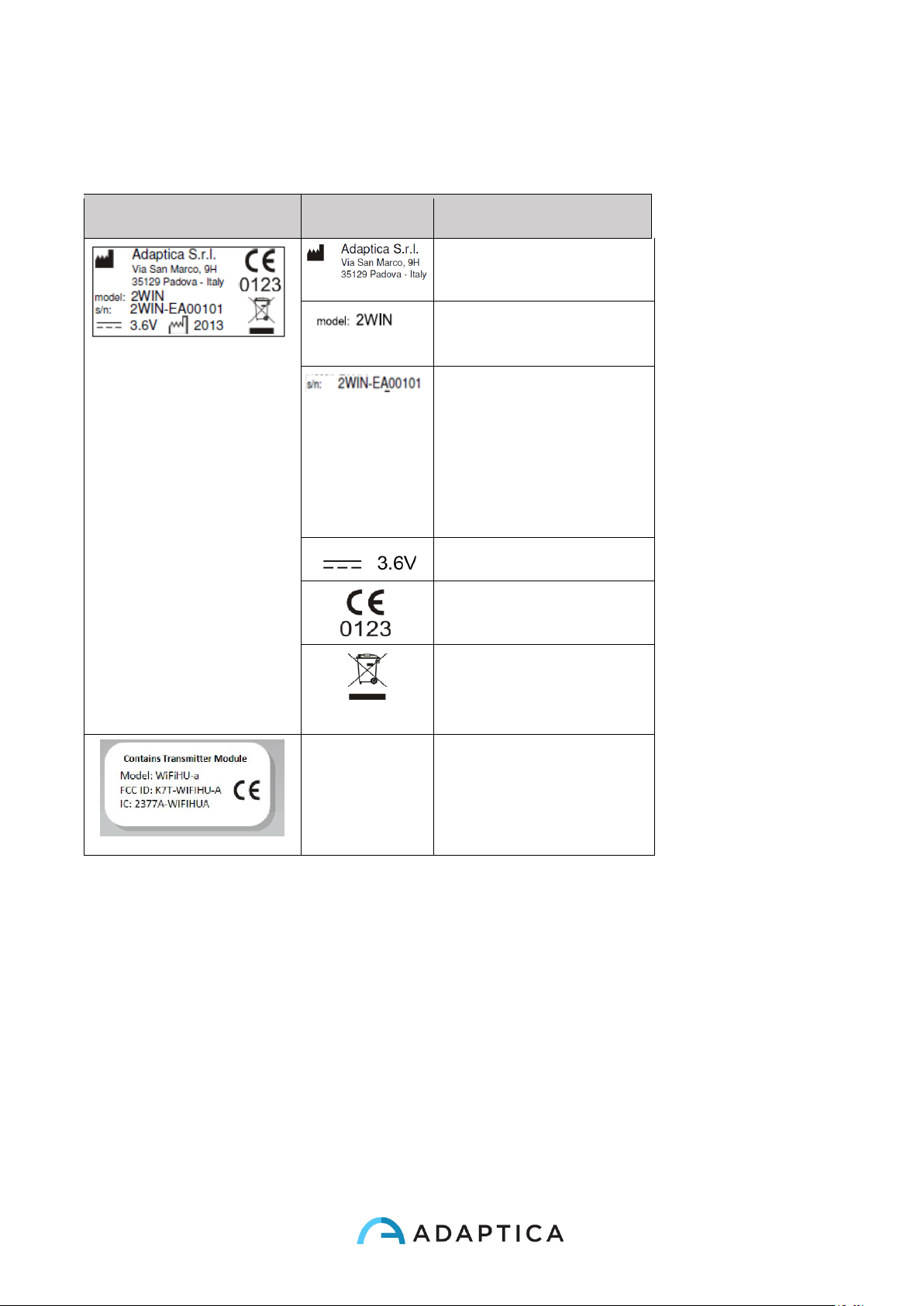
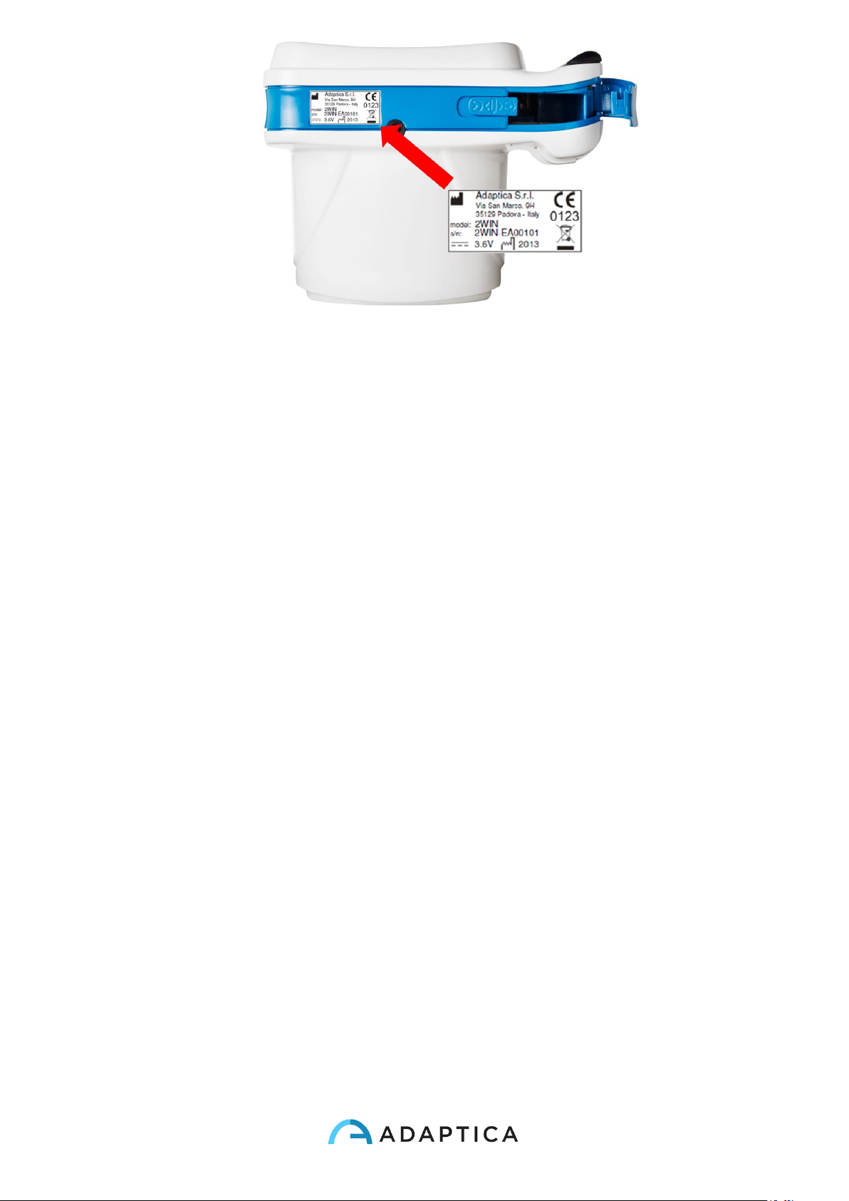
Labels
Label
Detail
Explanation
Manufacturer identification
data: name and address
Model name
Serial number, including
manufacturing date:
2WIN = model code
D = year (A=2009 B=2010 ..)
F = lot
00001 = unique serial number
Battery operating voltage
CE mark and Notified Body
identification code
Electrical / electronic device
subject to the WEEE Directive
on waste disposal
Model
Fcc ID
IC
Identifies the Wifi transmitter
module
Page 17
17
Page 18
18
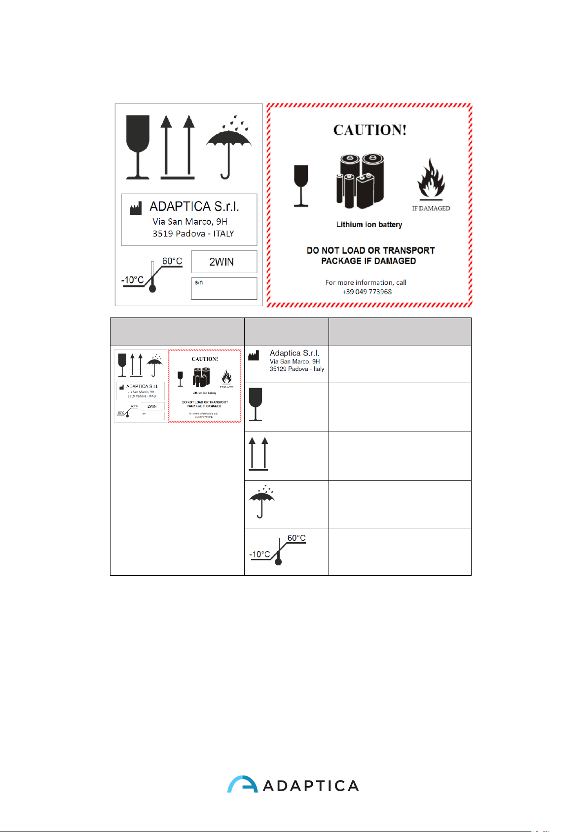
Package labeling
Label
Detail
Explanation
Manufacturer identification
Data: name and address
Fragile – handle with care
This side up – do not reverse
Keep dry
Storage minimum and
maximum temperature
Page 19
19
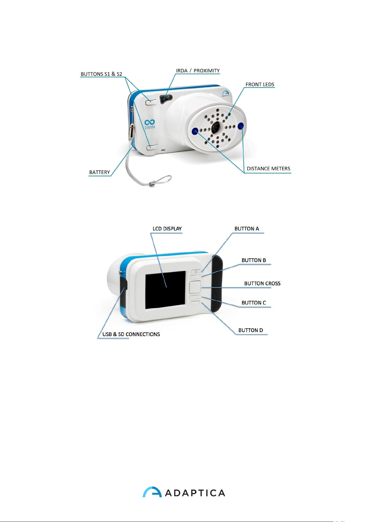
Interfaces
Front View
Rear View
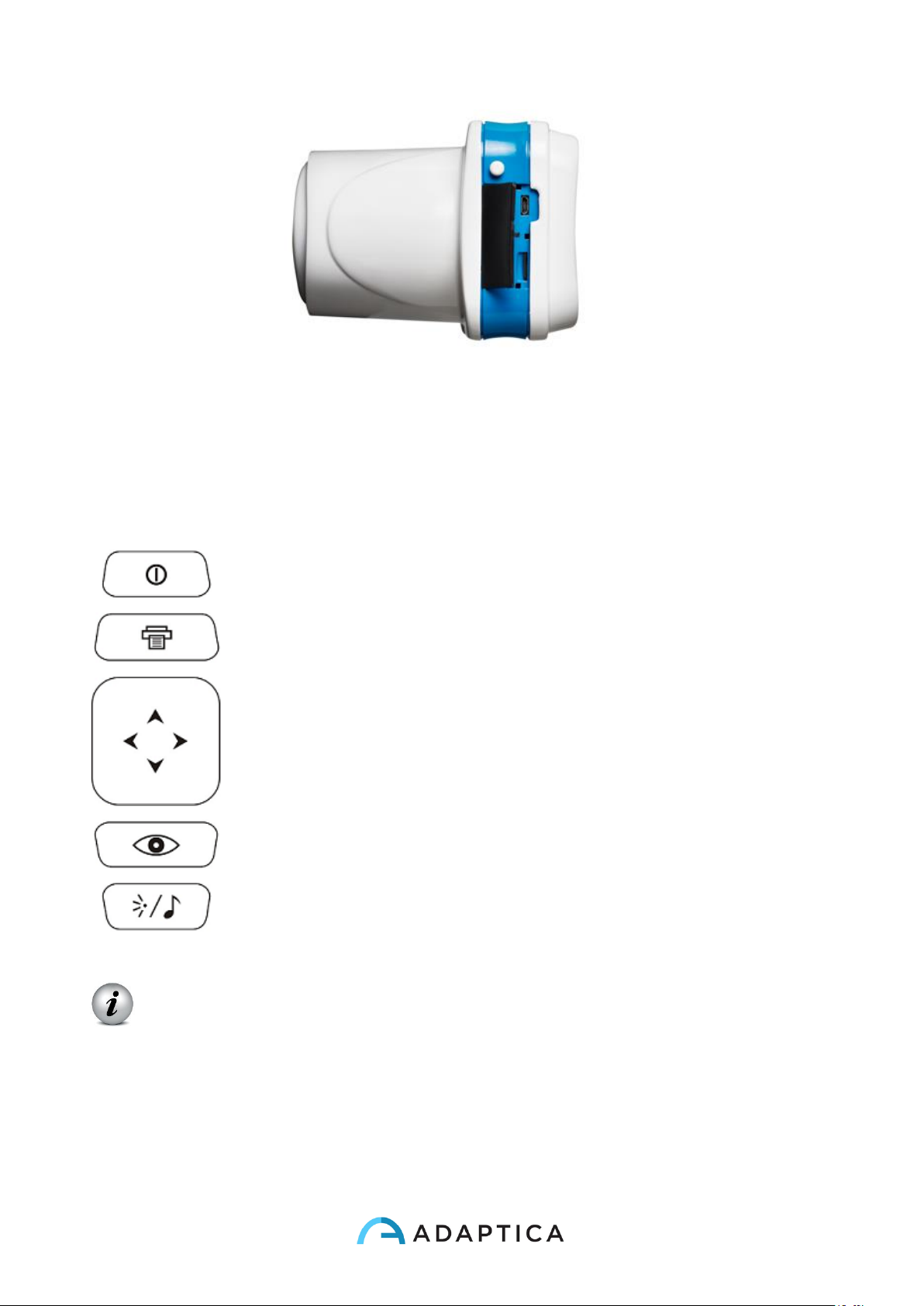
Inside the USB & SD connection door there are a Micro USB port and a Micro SD card
holder.
Page 20
20
Open connection door
On the bottom of the device there is also a 1/4”-20 threaded hole for a tripod.
A summary of the functions of the buttons is reported below.
Patient side:
BUTTON S1 & S2
Operator side:
BUTTON A
BUTTON B
CROSS BUTTON
BUTTON C
BUTTON D
IMPORTANT NOTE: the buttons have different behaviours within the different
submenus, these will be described in the manual in the corresponding paragraphs.
Long CENTRE push to display Contextual help that explain buttons functionality.
The CROSS BUTTON features contextual functions:
At starting the CROSS BUTTON is used to activate the menu and navigation:
Page 21
21
• push CENTRE to enter menu or to say OK;
o push RIGHT to go down into the submenu;
o push LEFT to go up from the submenu;
o push UP to scroll up the menu;
o push DOWN to scroll down the menu;
• fast RIGHT push: activates auxiliary window. This window displays the results of main
application (screening) and additional application;
• long LEFT push: activates keyboard to insert patient name and date of birth;
• long RIGHT push: Screening Mode: Selection of age interval for standard screening:
push RIGHT to switch between 'Ok' button, 'Cancel' button and the list of age intervals.
To move inside the list of age intervals, press CENTRE button. (NOTE: if the date of
birth has been already inserted via the long LEFT push, then the age interval is
automatically set);
• long UP push: changes positive and negative cylinder representation for the running
measurement;
Menu tree is described in the Menu paragraph.
During the examination some keys change their function:
• push LEFT to toggle ON/OFF the sound;
• push RIGHT to toggle ON/OFF the light;
After the measurement:
• push CENTRE to enter menu;
• push RIGHT to display the auxiliary window;
Active keyboard mode buttons:
• Cross button CENTRE: select the field (or letter) highlighted;
• Start button: Enter;
• Cross button, UP/DOWN/RIGHT/LEFT buttons: move between characters;
• Button A: exit;
• Button B: moves the cursor in different fields;
• Button C: backspace;
• Button D: resume;
Page 22
22
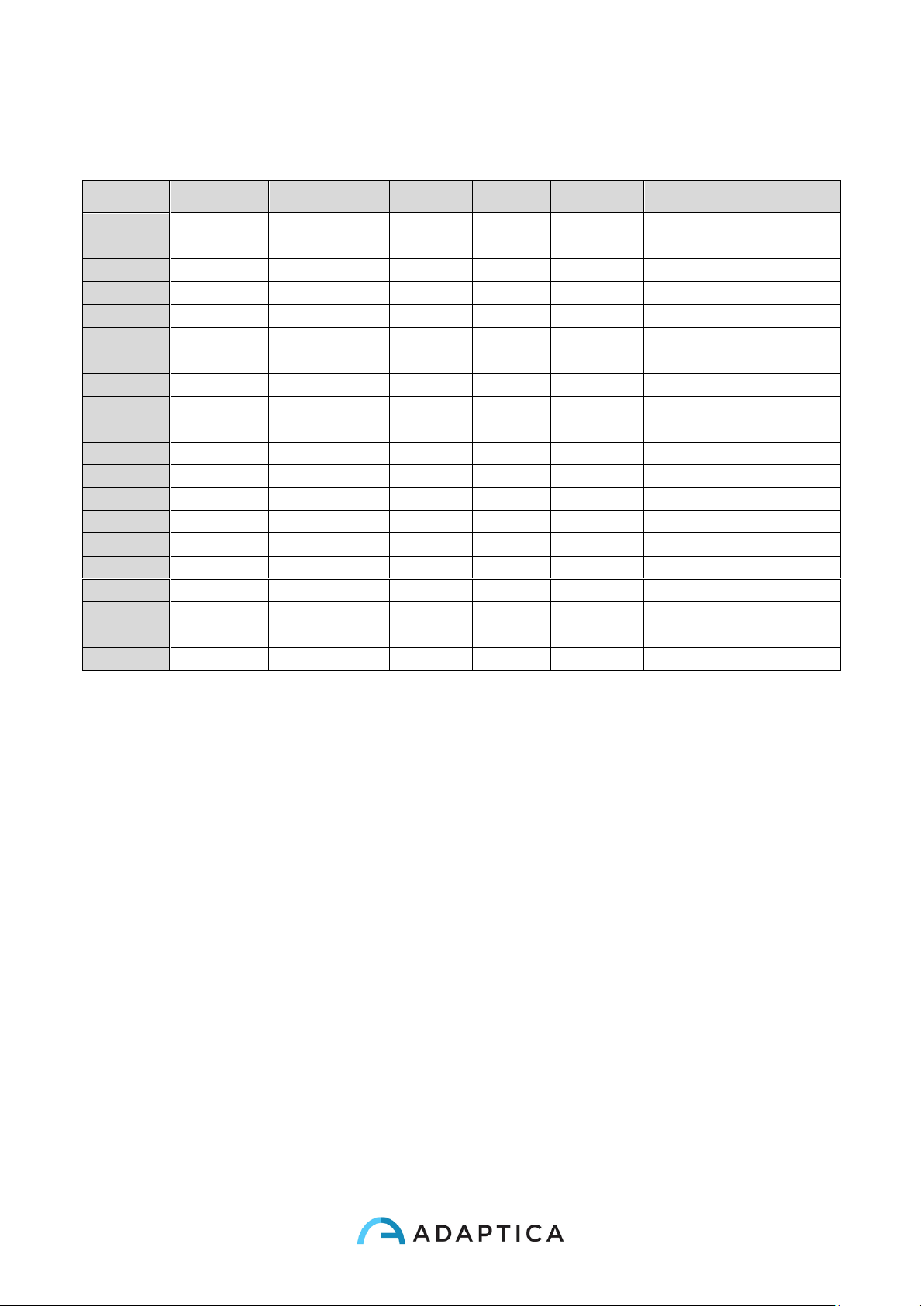
All the button functions are summarized in the following figure:
BUTTON
HOME
BROWSE
KEYBOARD
DATE TIME
SCREEN
AGE
MENU
IN MEASURE
Hold A
on/off
on/off
A 2WIN Applications
Exit
Exit
cancel
cancel
exit
--
Hold B
print
Print
B Zoom
Zoom
Change field
Change field
Change field
Change field
--
Up
--
Patient UP
move
Increase
change field
Move Up
--
Up-hold
toggle refraction
toggle refraction
--
--
--
--
--
Down
--
Patient DOWN
move
Decrease
change field
Move Down
--
Down-hold
BROWSING on
BROWSING off
--
--
--
--
--
Menu
Enter menu
Enter menu
Ok
Click
Click(Select)
Select
--
Menu-hold
help
Help
Help
help
help
help
--
Left
restore last valid
measure
show patient data
move
change field
change field
Go to Parent/Exit
Toggle Sound
Left-hold
Keyboard
Keyboard
--
--
--
--
--
Right
screenResult
screenResult
move
change field
change field
Go to child
Toggle Light
Right-hold
screenAge
screeninAge
--
--
--
--
-- C change eye
--
canc
--
--
--
--
Hold C
Notification Center
Notification Center
--
--
--
--
-- D attention
BROWSE FILTER
resume
--
--
--
Toggle Sound
Hold D
quick menu
--
--
--
--
--
--
S1/S2
Start Measure
browseOFF
done
--
--
--
Stop Measure
Hold S1/S2
Focusing
--
--
--
--
--
--
Page 23
23
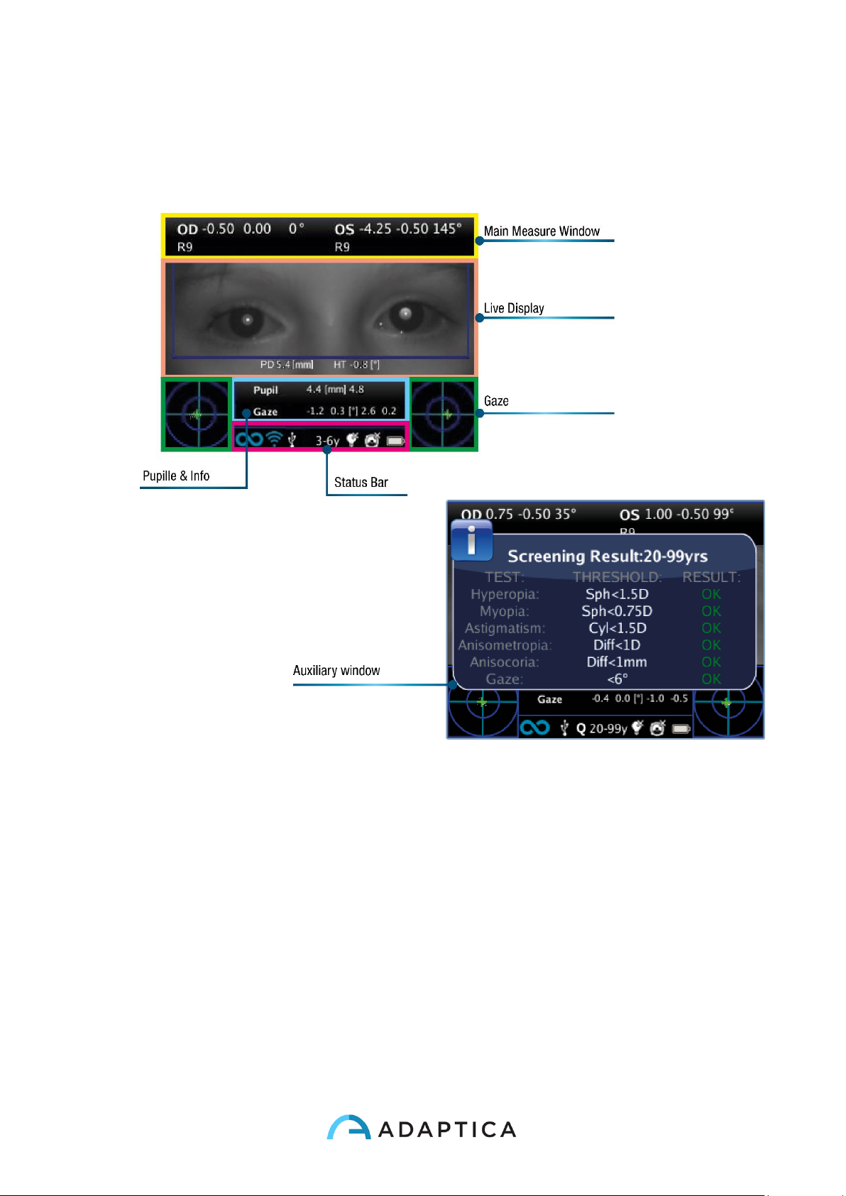
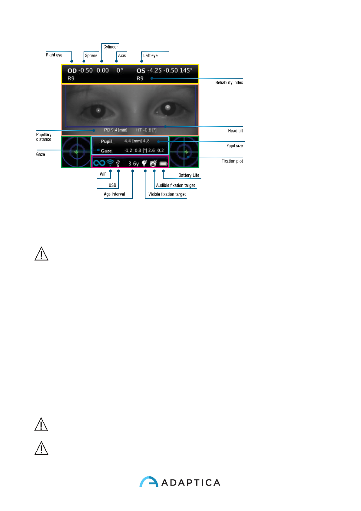
Graphical user interface
The graphical user interface is displayed in these figures:
Page 24
24
8. Precautions
Electromagnetic compatibility
This device has been tested and found to comply to the limits for medical devices
contained in IEC60601-1-2 and in Medical Device Directive 93/42/EEC. These limits are
intended to provide reasonable protection against harmful interference in a typical medical
installation. This instrument generates, uses and can radiate radio frequency energies
and, if not installed and used in accordance with these instructions, may cause harmful
interference to other devices in the vicinity. However, there is no guarantee that
interference will not occur in a particular installation. If the system does cause harmful
interference to other devices, which can be determined by turning the system off and on,
try to eliminate the interference by adopting one or more of the following measures:
• reorient and/or relocate the receiving device;
• increase the distance between the devices;
• In case of charging of the device, connect the system to an outlet on a different
circuit than that to which the other devices is connected;
• consult the manufacturer or field service technician for help.
The area where the device is to be installed has to comply to the IEC/ISO standards
related to the medical use of an area.
The device must NOT be used in oxygen rich environments or in presence of
flammable products.
Page 25
25
The device must not be installed in a room exposed to chemical-physical aggressive
agents (such as as sulfides, salt, dust, etc.), nor exposed to direct sunlight or lack of
ventilation, high humidity, sudden surges or drops in temperature. The safety and
efficiency of the instrument are not guaranteed under these conditions.
Light radiation
CAUTION – The light emitted from this instrument is potentially hazardous. The longer the
duration of exposure, the greater the risk of ocular damage. Exposure to light from this
instrument when operated at maximum intensity will exceed the safety guideline after 30
minutes.
Do not stare at the light sources of the device from a distance lower than 1 m.
Precautions and general warnings
The clinical interpretation of the data provided by the device is restricted to licensed
eye care practitioners.
The process of making a diagnosis using the device results is the responsibility of the eye
care practitioner.
A device specific training is required for any operator to become able to use the system.
For the correct use of the device it is mandatory to read carefully the instructions in § 8 -
Operative information.
Do not open the device: this could lead to electric shocks or damage to the system.
No modification of this equipment is allowed.
Do not use the instrument in the event that the cover or other parts of the device have
been removed.
Only technicians authorized by the Manufacturer may service the device. The
Manufacturer cannot be held responsible for system safety should the device be opened,
repairs carried out, third parties software be installed, or parts be replaced by unauthorized
persons.
Inside the 2WIN SD memory card is stored the patient data. This information can contain
personal information such as name/surname/age. This information management is
responsibility of the operator.
Do not expose the device to water: this could lead to fire or electric shock.
Do not use the device while it is attached to the wall adapter for charging the battery.
Any USB wall adapter and any battery charger used to charge the battery, when not
provided by the manufacturer, shall comply EN 60950-1.
The device needs to be operated in a semi dark room, in order to help pupil dilation.
Page 26
26
9. Operative information
Register your 2WIN
Registration takes less than 1 minute!
It's highly recommended to register your 2WIN at:
http://www.adaptica.com/user-registration/
Registering your 2WIN instrument you will be updated from Adaptica on any recent
news or software update of the 2WIN.
Operating conditions
The device needs to be operated under the following environmental conditions:
Temperature: 10 – 40 C° (50 – 104 F°)
Humidity (max): 90% not condensing
Unpacking
The box contains (default configuration):
• the electronic version of the operating manual (inside the microSD)
• the 2WIN device
• two rechargeable batteries
• a microSD memory card
• a USB cable (microUSB to USB-A)
• an external battery charger to charge the battery outside 2WIN
• an occluder (infrared patient’s eye occlusion system)
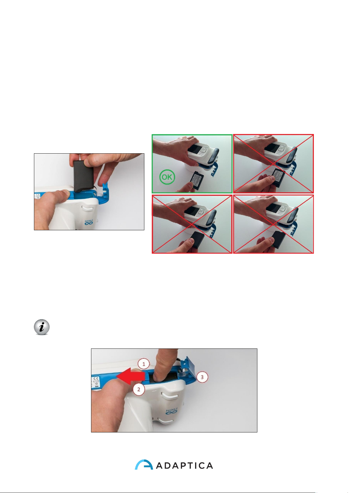
Open the battery lock and insert the battery. Close the battery door and lock it (follow the
following instructions to insert the battery in the proper way).
Before inserting the battery, charge it totally.
Page 27
27
Insert battery
To insert the battery: slide the battery lock, hold it and gently open the battery door located
in the lower side of the device. Insert the battery. Pay attention in inserting the battery with
its connector facing down towards the instrument's inside so that the connector of the
battery matches the connector inside the device.
Close the battery door and lock it.
Extract battery
To extract the battery: (1) slide completely the battery lock, (2) hold it firmly and (3) gently
open the battery door located in the lower side of the device.
WARNING: Don't try to force the opening of the battery door if the battery lock
is not completely opened.
Page 28
28
Battery-charging
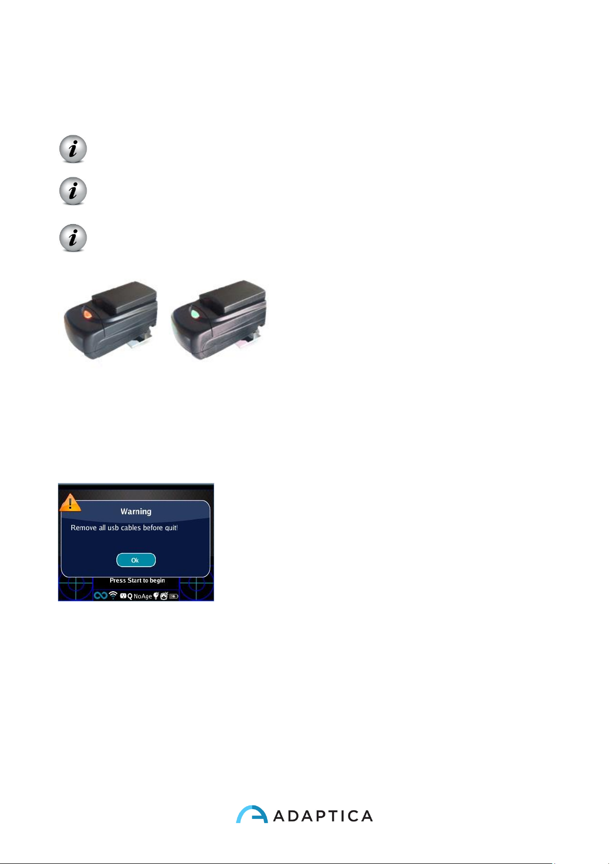
Please load the batteries with the external battery charger provided.
On first usage the battery needs to be charged for at least 4 hours.
Batteries must be charged at least once every 30 days.
Slide completely the battery lock and extract the
battery, insert the battery into the external battery
charger. Please align battery contacts with
charger. When the battery is fully charged, the
light of the charger will become completely green.
The recharge option via USB port connected to the computer is for emergencies. In fact, to
extract the battery and use an external wall battery charger is the usual procedure allowing
a good life cycle of both battery and 2WIN device.
Please notice that the device will not be able to perform any exam while connected via
micro-USB port.
When the device is connected to a computer via USB port
the turning off is prevented. When you try to switch off the
2WIN a warning will advise you to remove usb cable.
Before operation
After charging the battery, be sure to set up date and time. Current date and time will be
used into measurement printout. As soon as the battery is assembled and charged, and
time has been set, the device is ready for operation.
The device has an automatic hardware self test procedure that can be activated as an
option on the instrument MENU under FUNCTIONS/AUX/AUTO TEST. This procedure
may be executed any time to verify hardware integrity.
Page 29
29
Data management disclaimer
When turned on the first time, 2WIN present a disclaimer document related to the
management of data telemetry of the instrument. The operator is asked to read the
document and accept the terms, if not 2WIN will work but some functionalities will be
disabled (Telemetry and Remote access). You can read the document at the end of this
manual (Appendix A) for all the details.
10. Operative instructions
(Please refer to Chapter 7, Par. Interfaces for fast reference)
Power ON / Power OFF
To power on the device, push the BUTTON A.
(To turn OFF the device long press the BUTTON A then, when the question “Are you sure
you want to quit?” appears, push the CROSS BUTTON, center, to answer OK)
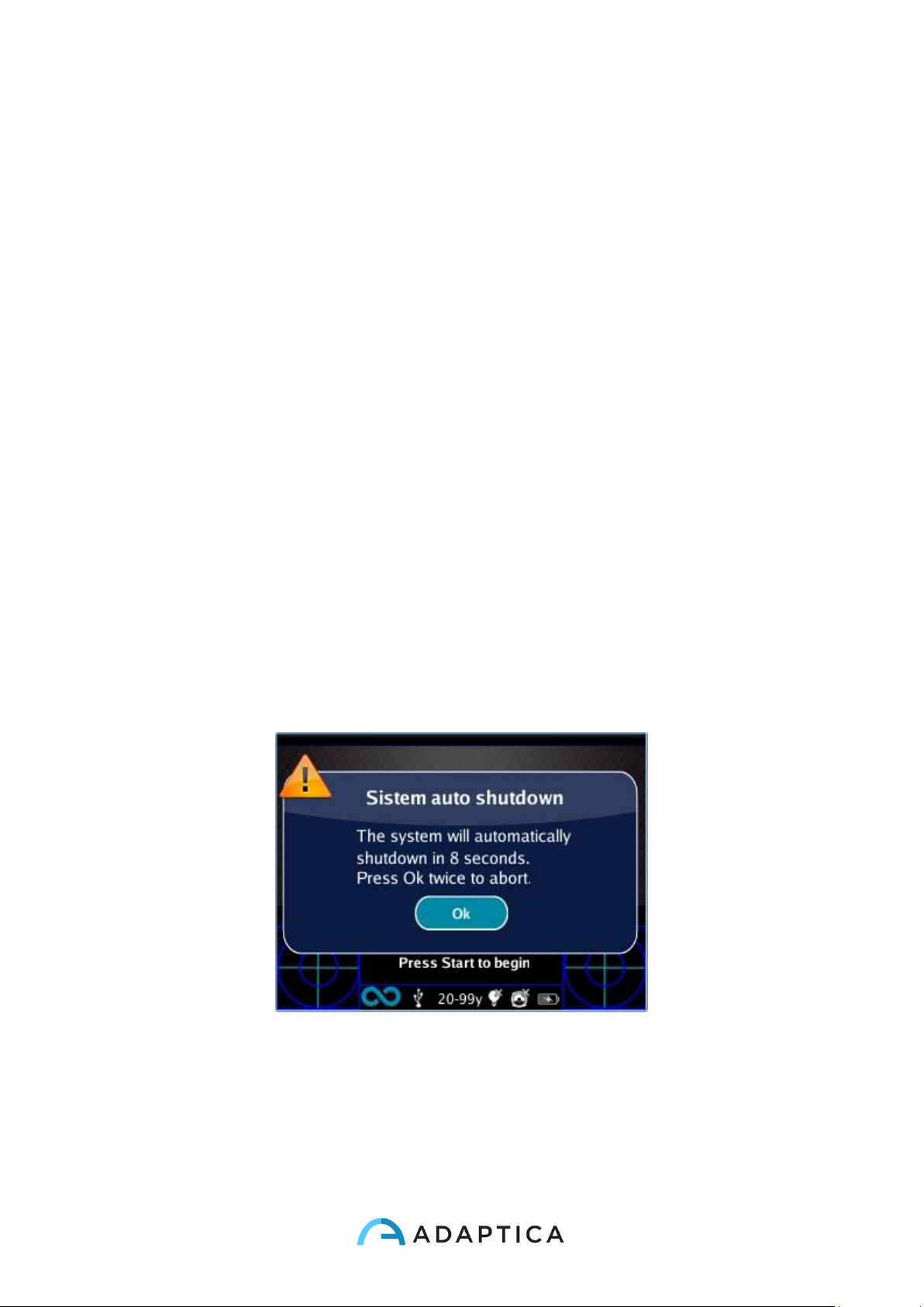
While the instrument is on, the monitor reduces the brightness after 30 seconds of
inactivity. Then the monitor switches off after 30 seconds more. After 600 seconds, the
device turns on, emits a sound alert, and shows a warning telling that after 30 seconds it
will automatically shutdown.
Default Autoshutdown Time is 10 min.
Autoshutdown time (changeable from a minimum of 10 to a maximum of 180 minutes, in
steps of 5 min), can be customized by selecting from Menu > Settings > Aux >
Autoshutdown Time.In order to operate the instrument it is important to execute the
following four steps:
Page 30
30
a) Environment setup
b) Instrument setup
c) Preparation of the patient
d) Measurement
Page 31
31
a Environment setup
For a proper use of the device it is important to prepare the environment for the
examination.
✓ Verify adequate light conditions
The ambient light should be dim, there should be no direct light pointed towards the
instrument and every direct source of light should not be seen by the device or reflected by
eyes of the patient. In case of bad light conditions during the measurement a message
may appear indicating the specific condition.
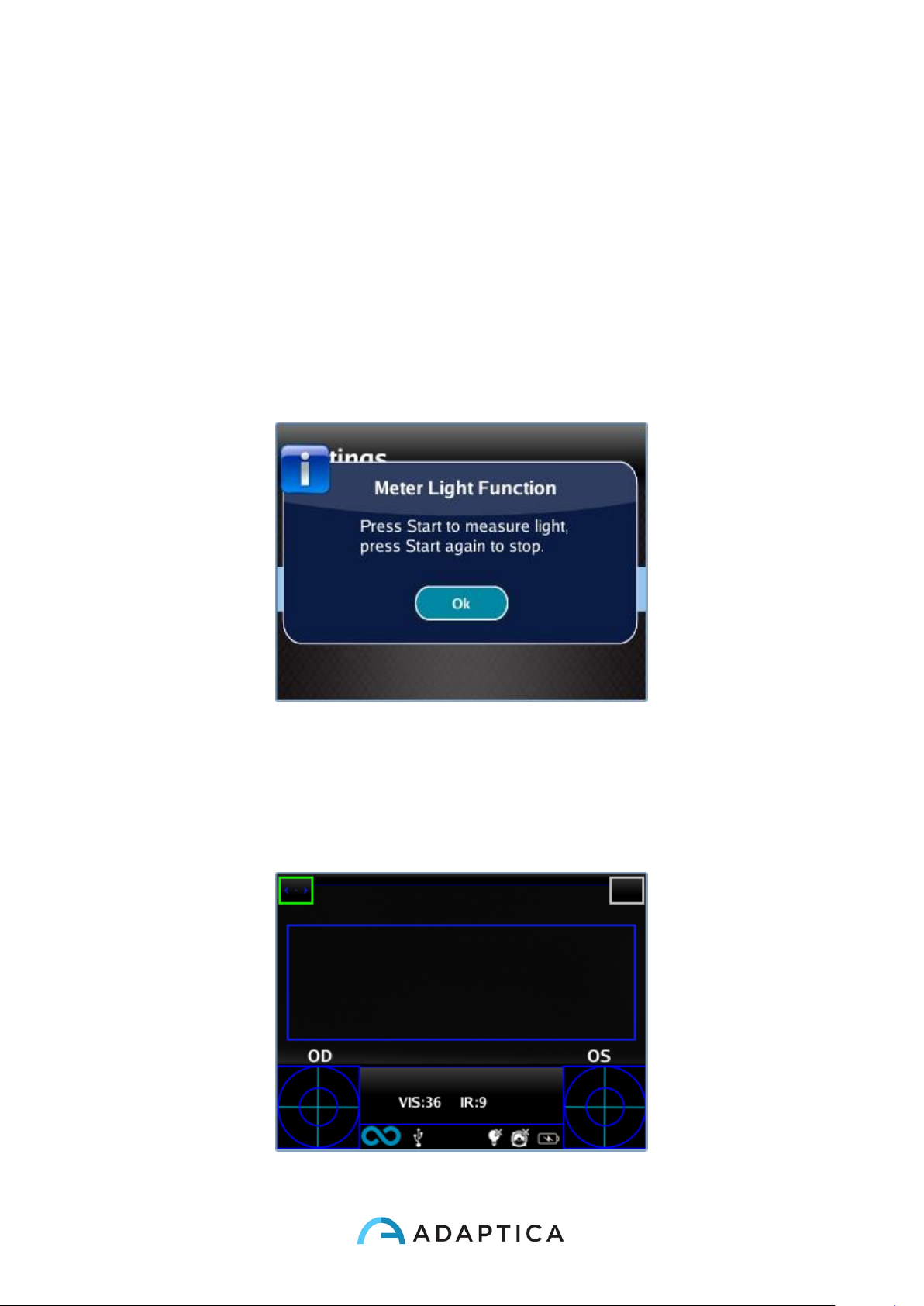
The device can be optionally used to perform an evaluation of the ambient light: in Menu >
Functions > Light Meter the following screen will be displayed.
Then press CENTRAL BUTTON to answer OK to confirm light measurement mode and
press S1 or S2 button to start the evaluation:
• Wait that the “age circle highlight” disappears and read the VIS and IR values
• VIS and IR will represent visible light evaluation, in a 0 to 65535 range, and infrared
light evaluation, in a 0 to 255 range.
Press S1 or S2 button to stop the evaluation.
Page 32
32
Good light conditions are equivalent to a value of VIS between 30 and 80, and of IR less
than 30.
b Instrument setup
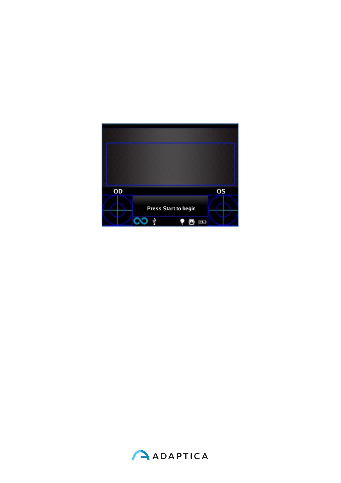
As soon as powered ON, the device will perform a fast auto-test, then it will turn directly to
exam mode, and the display will show the screen depicted below.
As the device features different kinds of measurements, and different exam modalities, an
instrument setup must be performed before performing an examination or a sequence of
examinations.
Main settings are related to measured eye and interactivity.
Other settings are described in the Menu paragraph.
Eye selection
There are three options related to which eye of the patient is being measured. By pushing
in sequence the Eye Selection Button (BUTTON C) on the device the user can toggle
between three type of measurements:
• LEFT EYE: only left eye is measured (the blue rectangle covers only the right side
of the live area on the display).
• RIGHT EYE: only right eye is measured (the blue rectangle covers only the left side
of the the live area on display).
• BOTH EYES: both eyes are measured (the blue rectangle covers the whole live
area on the display).
The choice is shown on the display by the presence of the signs OS or OD or both on the
appropriate side of the display.
Page 33
33
Please notice that the there is an inversion of left and right due to the fact that the patient
and the machine are one in front to the other. Therefore the sign OS will appear on the
right half of the screen, and viceversa.
Performing a monocular examination, the contralateral eye can be covered or kept open at
(choice of the Operator).
Power-ON screen with OS
Interactivity/attraction of the patient
Interactivity represents the set of features built to attract the attention of the patient and
they are changed by means of BUTTON D. Interactivity can be of three types:
• SOUND: at the beginning of each measurement the system starts a Jingle to catch
the patient's attention. The Jingle and the volume can be chosen by the operator
through the menu.
• COLOR LED: at the beginning of each measurement the system starts a flash
sequence of red green and blue led in order to catch patient's attention. The LED
sequence, the color and the intensity can be set through the menu.
• SOUND + COLOR LED: both the previous.
The type of operative interactivity is indicated on the bottom bar by means of these
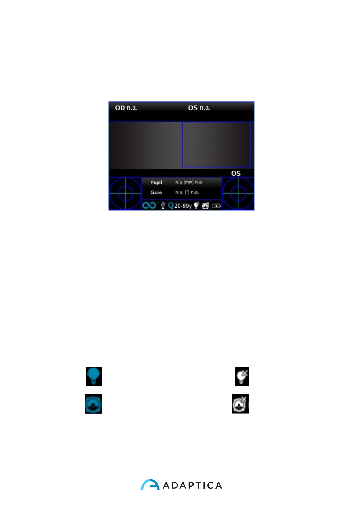
symbols on the top bar:
light on
light off
sound on
sound off
Page 34
34
Patient data
After a measurement patient data can be inserted.
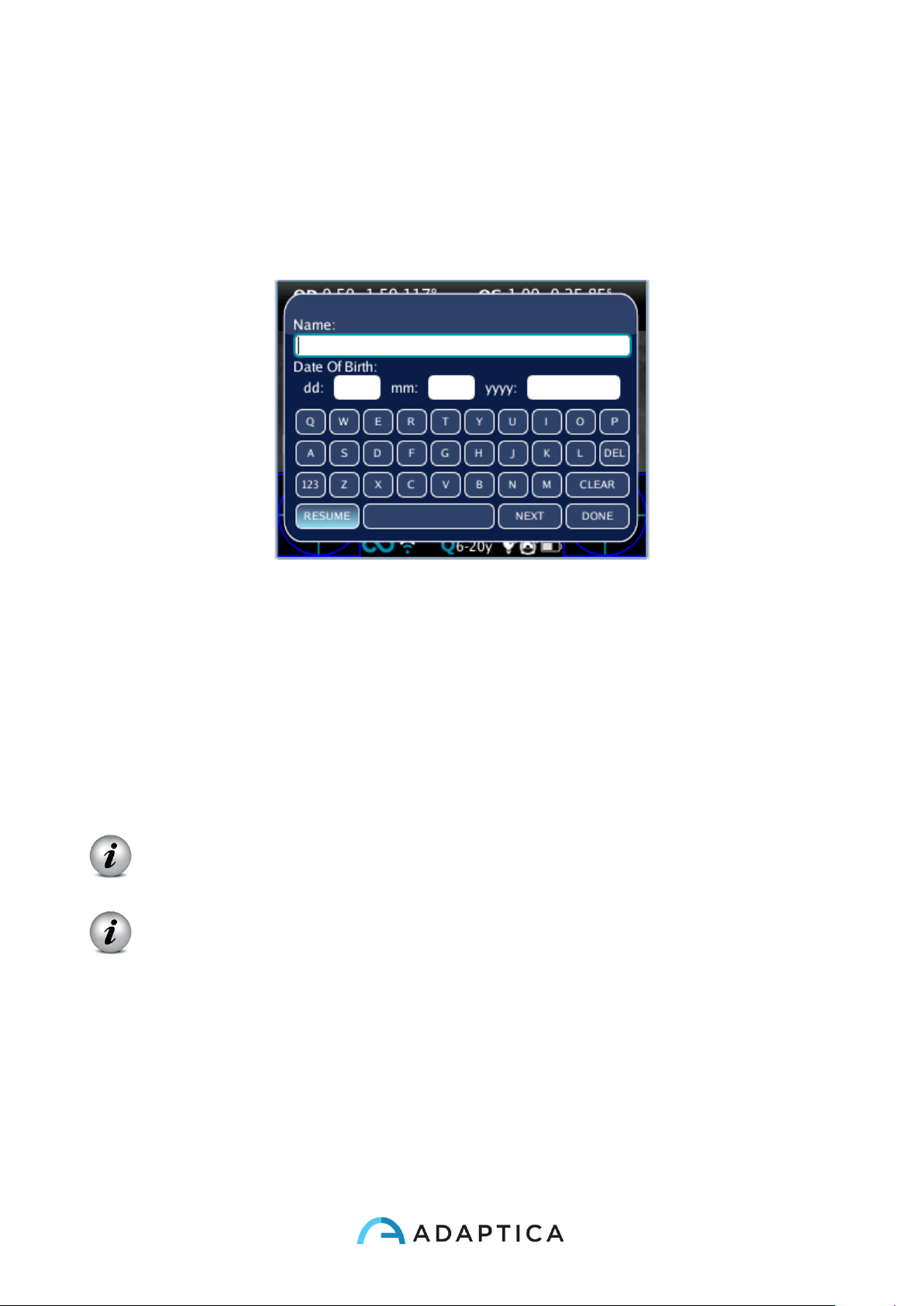
In the CROSS button press and hold the left button until the patient data keyboard
appears. Insert name of the patient and date of birth (optional), as shown in the following
figure:
During active keyboard, use the following buttons:
• Cross button center: select the field (or letter) highlighted
• Start button: Enter
• Cross button up/down/right/left buttons: move between characters
• Cross button, central button and/or Start button: Enter
• Button A: exit
• Button B: move cursor in different fields
• Button C: backspace
• Button D: resume
IMPORTANT NOTE. A new measurement cancels the patient data.
To resume the last patient data, enter in keyboard active mode (long press left) and
press Button D / resume.
IMPORTANT NOTE: If 2WIN has Wi-fi capabilities, it's possible to insert patient
data in a different way. Look at paragraph 9 “Wi-fi connection” pag.61.
Page 35
35
Browsing Mode
The browsing mode allows to recover patient's data previously saved in the 2WIN SD
memory. Holding the down button in the Home window, the Browsing mode is entered.
The UP and DOWN buttons permit to move between different patients: the data (Patient
number, name, date of birth, Age Selection, exam date) is shown for some seconds and
then disappears. However, patient data can be recalled by pushing the left button. When
the list of patients is at the end of the browsing, the display restarts from the first patient
and a refreshing icon (circular shape arrow) appears.
If a stored patient data has been saved with a 2WIN sw version previous to 2.0 (but not
lower than 1.4), then the browsing mode shows an exclamation point icon indicating that
some fields are incomplete.
It is possible to add a filter in the patient name and / or number for the search of a specific
patient by pressing the Button D; if filter is inserted, an icon shows that the filter is active.
If an error occurs during the measurement and the message appears, this last message
can be recalled by holding the button C.
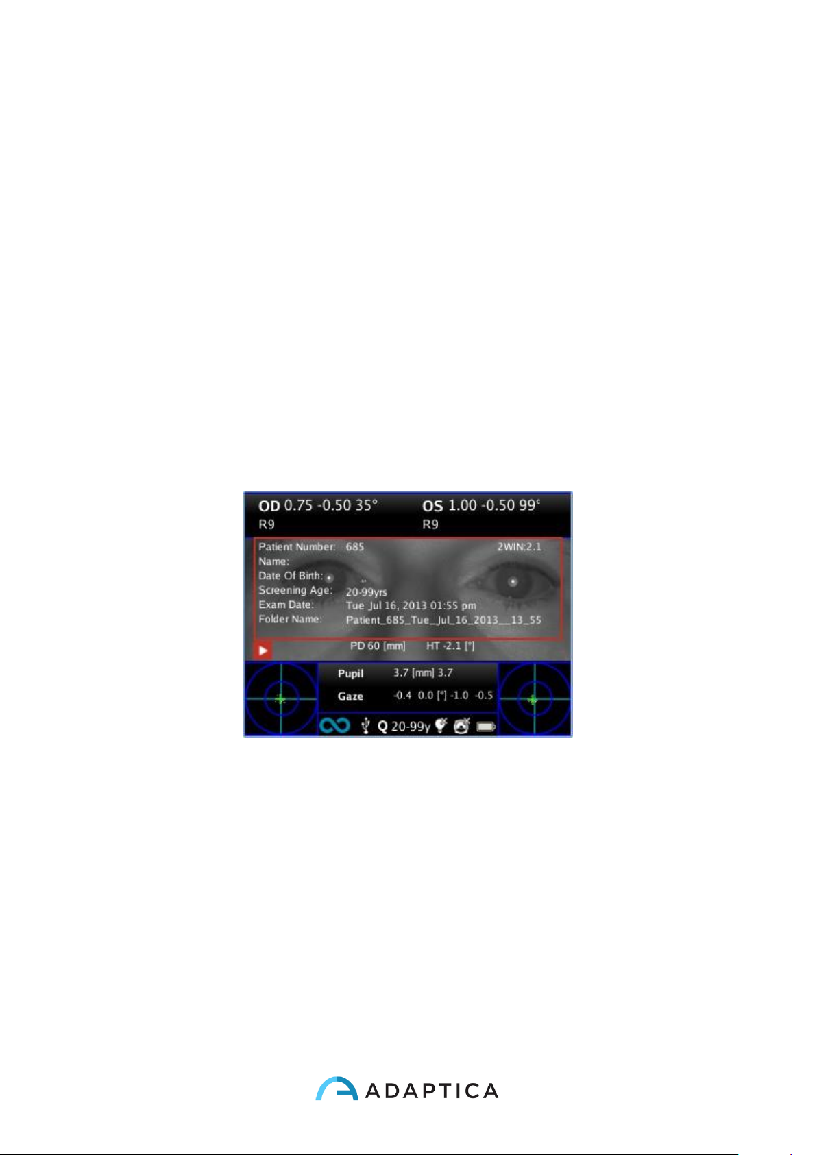
Browsing mode: recall of a possible patient.
When pressing the left button the patient's data is shown overlaying the image for a couple
of seconds. Data shown are: patient number, patient name, date of birth, age selection,
folder name, exam date and software version used to acquire and save the exam.
Page 36
36
c Preparation of the patient
During the exam the patient must look at the device, staring to the central front hole of the
device.
The operator shall instruct the patient to look at the device and to try to open wide his eyes
so to avoid eyelashes covering the pupils.
In case the patient is not collaborative, the operator should use interactivity features to
attract the attention of the patient itself, by activating either visible flickering lights, or
sound, or both. We recommend to activate first the sounds and the light only in extreme
case when the sounds are not enough.
In case of infants, the patient may be held on the parent's legs during the examinations.
Also, it is a good practice to ask the patient to try to keep the head horizontal, although the
device will evaluate and automatically compensate for inclination, when measuring the
axis of the refraction.
In case of monocular measurement, ask the patient to cover his other eye with a hand.
Page 37
37
d Measurement
The instrument, since the beginning of the examination, uses a top bar in the display that
gives feedback on the conditions for measurement: in particular, this bar becomes red or
green. When the bar is red, there are no conditions to acquire the images correctly, on the
contrary, when the bar is green, correct conditions for measuring are satisfied and images
can be acquired and processed correctly.
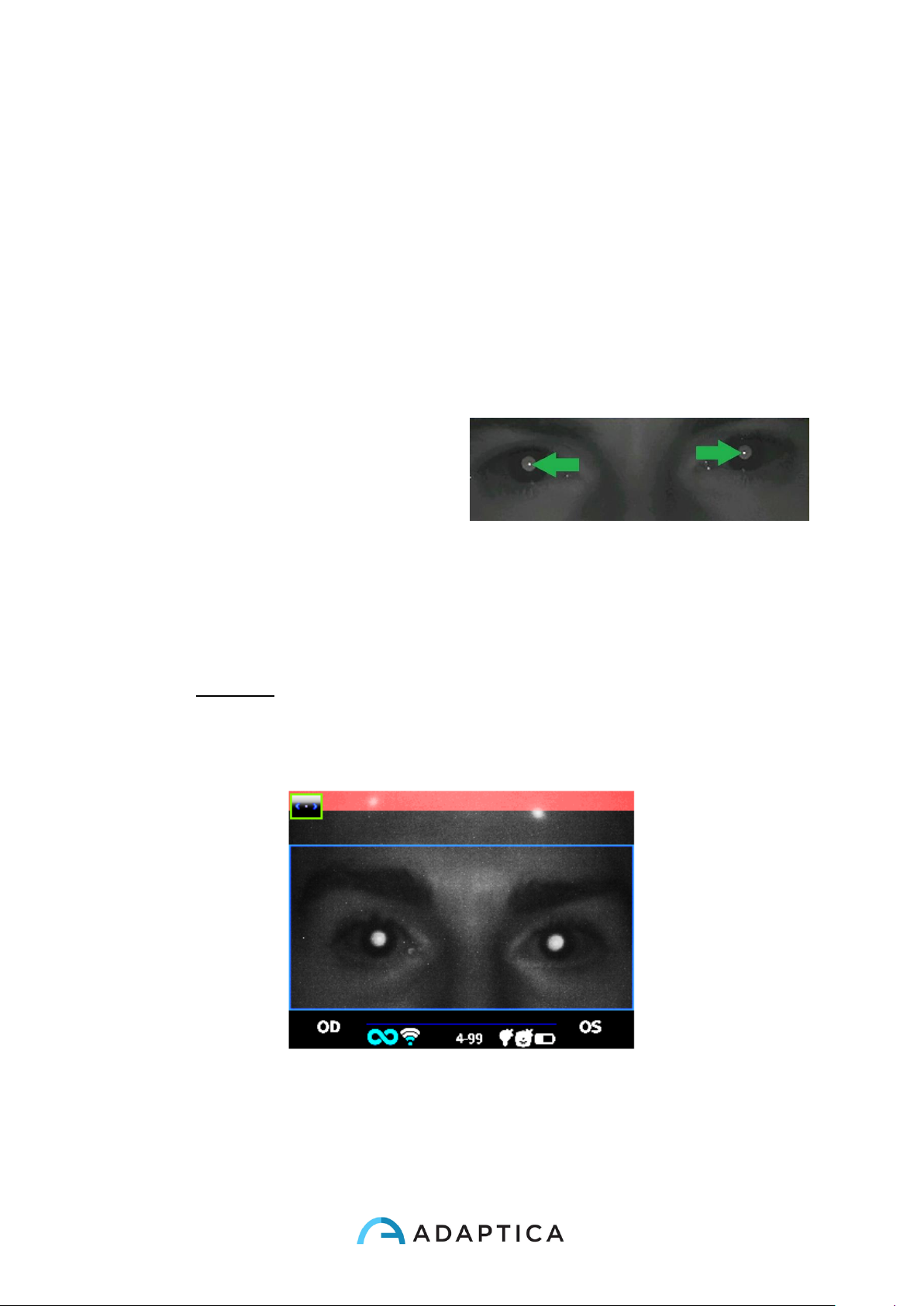
Measurement tips: usually the RED condition depends on a bad distance between
the 2WIN and the patient. When the top bar is RED adjust the distance between the
2WIN and the patient in order to focus the image and to obtain a GREEN top bar.
Try every time to focus as best as
you can, looking at the corneal
reflex. The corneal reflex focusing
indicator must be as sharp as
possible and as high as possible.
Sharp corneal reflexes
The steps to perform a measurement are summarized in the following list:
1. Once the conditions for the measurement are met, hold the device in your hands
and point it towards the patient.
2. Press and hold BUTTON S1 or S2, in order to start the measurement.
3. Center the eye/s of the patient in the display live area, inside the blue rectangle
(measurement area) – the message “FOCUSING” will appear.
Examination screen – bad focus
Page 38
38
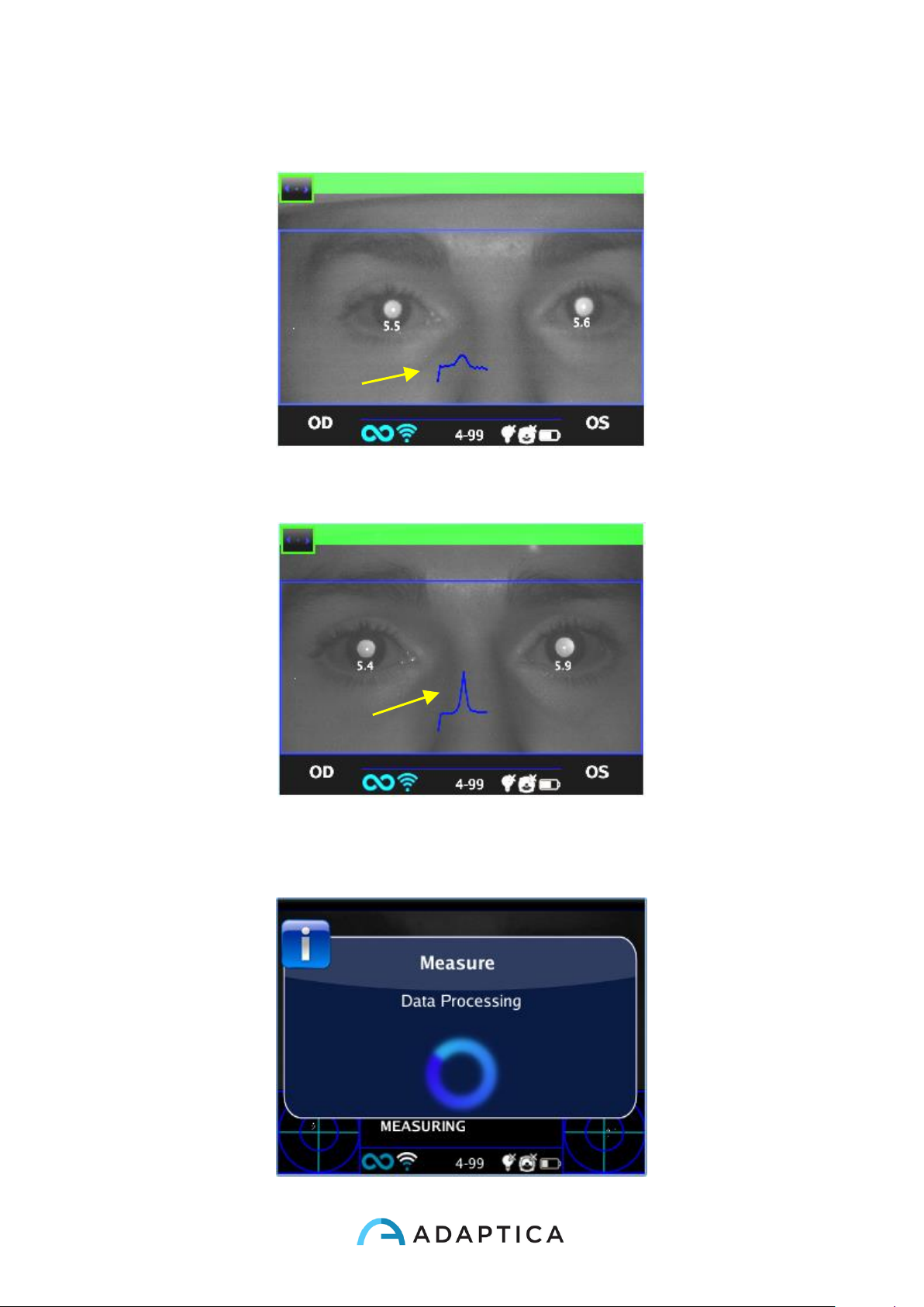
4. Adjust the distance to focus the image until the top bar is green and the focusing
indicator based on corneal reflex shape appears in the centre of the screen.
5. When the top bar is PERMANENTLY green and the focusing indicator reaches the
highest peak (as shown in the following photo) release the BUTTON S1/S2.
Examination screen – focus OK
6. Stay firmly in the condition in which the upper bar is green until the message DATA
PROCESSING appears on the display.
Page 39
39
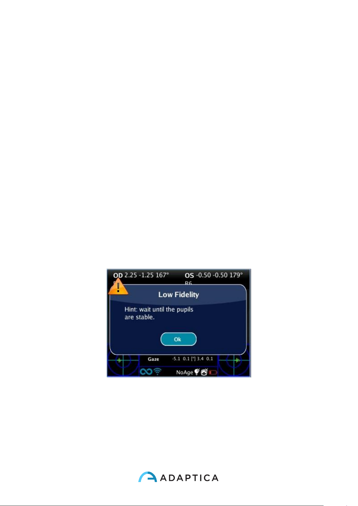
Data Processing
Wait until the measurement process is finished and the results of the measurement
are displayed on the screen.
A two beep sound indicates that the measurement has been correctly taken (this is
an option selectable from Measurement>Sound>Alerts>Ending Beep).
• If the ambient light is too high a message will appear warning about the unsuitable
condition.
• If something goes wrong during measurement, the measurement ends showing a
message indicating the cause of failure. These can be:
- Pupil/s too small or large;
- High IR noise;
- Unstable conditions of the data due to other eye problems;
- Other unexpected facts;
If this would happen try again. If the problem persist, suggest the patient to have a
specialist ocular examination.
• If an error occurs during the measurement and the message appears, this last
message can be viewed by Notification Center.
• If pupils diameter change during measurement, a message will be shown to display
after the measurement, please try to repeat the exam in stable light conditions.
Pupil diameter unstable
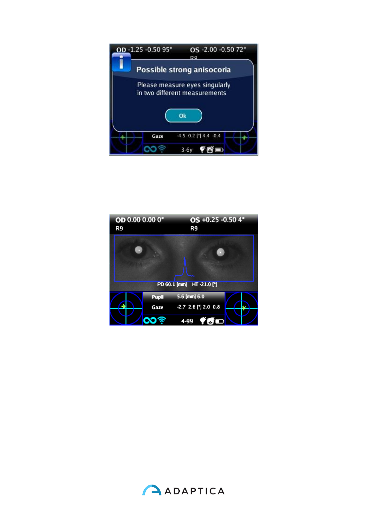
• If in binocular refraction the two eyes have very different pupil diameters (that
means anisocoria) a popup will appear on the display. It is suggested to measure
eyes singularly in two different measurements.
Page 40
40
Possible anisocoria
For any problem during operation, please refer to the chapter “Troubleshooting”.
7. At the end of the measurement the results are displayed:
Measurement screen
The results of the measurement are here described.
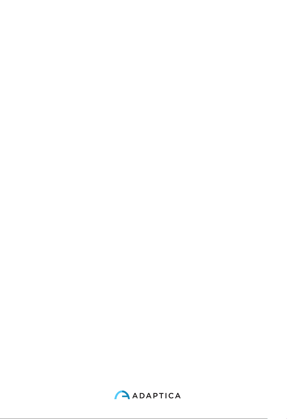
The top box contains, for OD and OS respectively, the values for sphere and cylinder, the
axis and the “reliability index”, a number between R1 to R9 (the higher the index, the more
reliable the measure). A measure with a low reliability index should be repeated. Please
notice that high ambient light will affect reliability index.
The message High M (Myopia) or High H (Hypermetropia) can appear below the OD/OS
symbol. This label indicates if the eye presents a diopters value higher that 5 D of
spherical equivalent.
If n.a. is displayed when High M/H appears, this indicates that the refraction is outside the
range of the 2WIN measurements range.
In case of binocular measurement, two values are shown overlapped to the image, inside
the blue rectangle; they are
Page 41
41
PD = pupillary distance
HT = inclination of the line connecting the centers of the two pupils, referred to the
ground
Axis angles are expressed according to TABO system.
Numbers for “Pupil” and for “Gaze” represent, for OD and OS respectively, pupil diameters
and horizontal and vertical (in this order) offset angles of the average position of the
corneal reflex on respect of the center of the detected pupil.
The Gaze is also graphically depicted for each eye in the two bottom corners of the display
in the form of a cloud of dots and an averaging cross inside two concentric blue circles.
When the cross is inside the smaller circle, the attention of the patient was high enough
during the examination.
In case of high Gaze values (cross outside inner circle) and collaborative patient, it is
recommended to repeat the exam after instructing again the patient about the need to
stare at the device, or, further, performing a monocular exam for each eye.
From the measurement screen the options are:
• Press and hold print button to save data to SD memory card and/or sent data to
IrDA printer (see Print paragraph);
• Press print button to make a ZOOM on the patient eye, move from the left to the
right simply switching with the right and left arrows of the joystick.
• Press S1 or S2 button (START BUTTON) to start a new measurement;
• Press C or D BUTTONs to change device setup for the next measurement;
• Press CENTRAL BUTTON to enter MENU (see Menu paragraph)
• Press LEFT BUTTON to recall last valid measurement performed (in case of invalid,
uncompleted measurement).
• Press RIGHT BUTTON for auxiliary window results, in normal 2WIN activities this
will bring to the amblyopia screening table.
• long left push: activates keyboard to insert patient name and date of birth: ACTIVE
KEYBOARD MODE.
• long right push: Screening Mode. Selection of age interval: push right/left/up/down
to switch between 'Ok' button, 'Cancel' button and the list of age intervals. Press the
center button to select the item highlighted (N.B. If the date of birth has been
already inserted via the long left press, then the age interval is automatically set).
Push “Ok” to save the choice.
Page 42
42
Zoom function
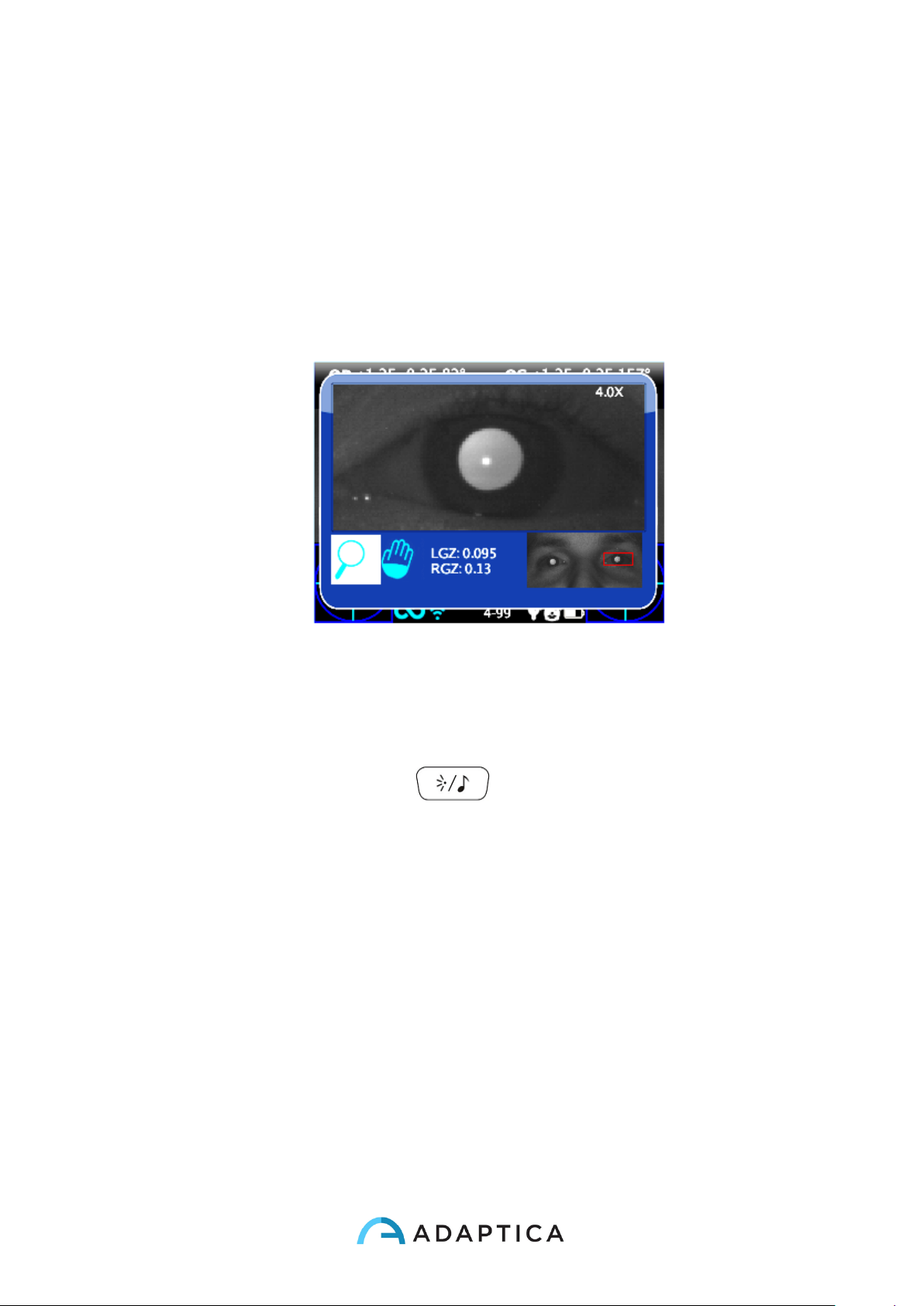
When the measurement is performed, the operator can make a zoom on the acquired
pupils of the patient. In order to do that SHORT PRESS the PRINT button. In order to
come back to the main visualization just short press the power botton.
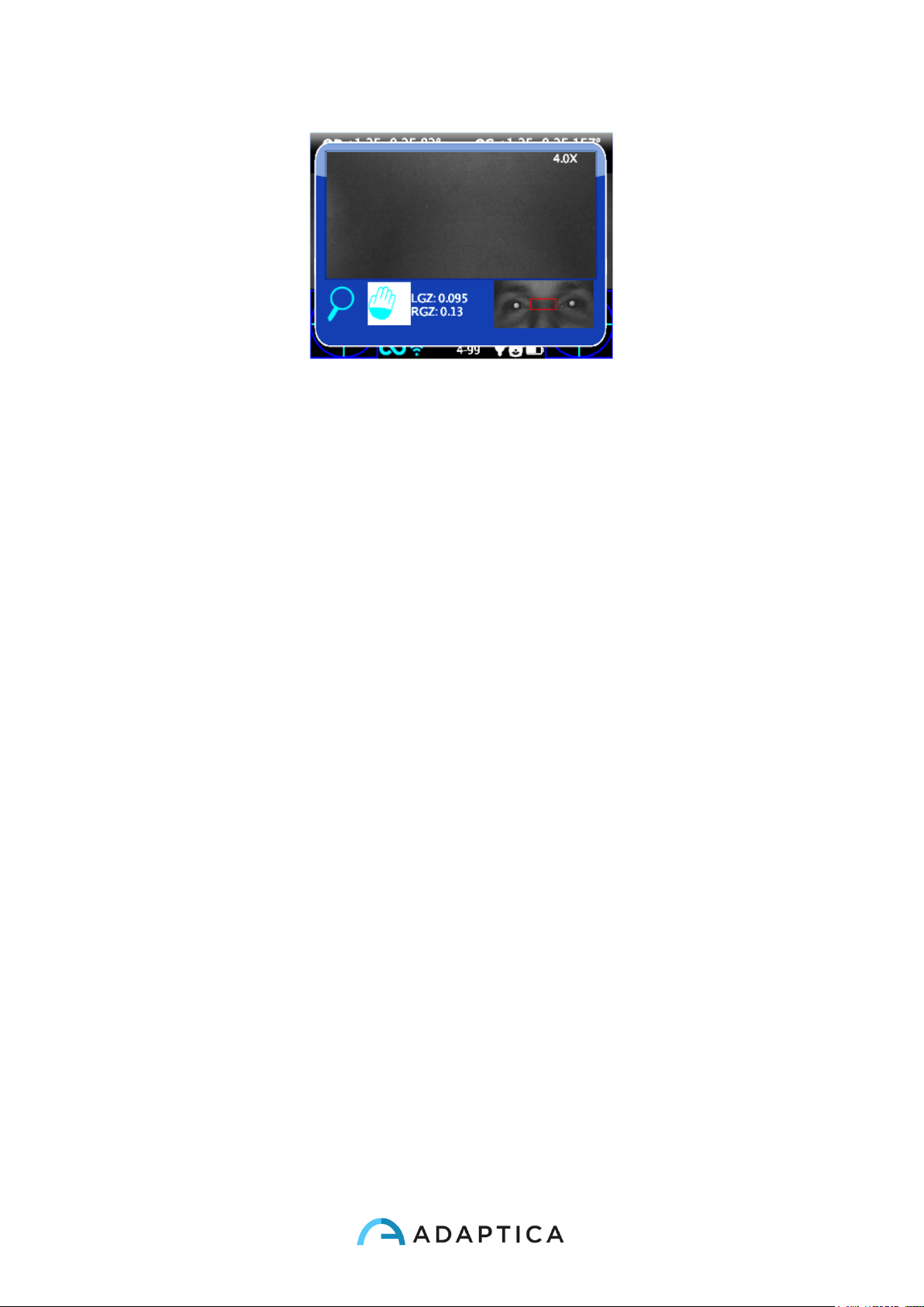
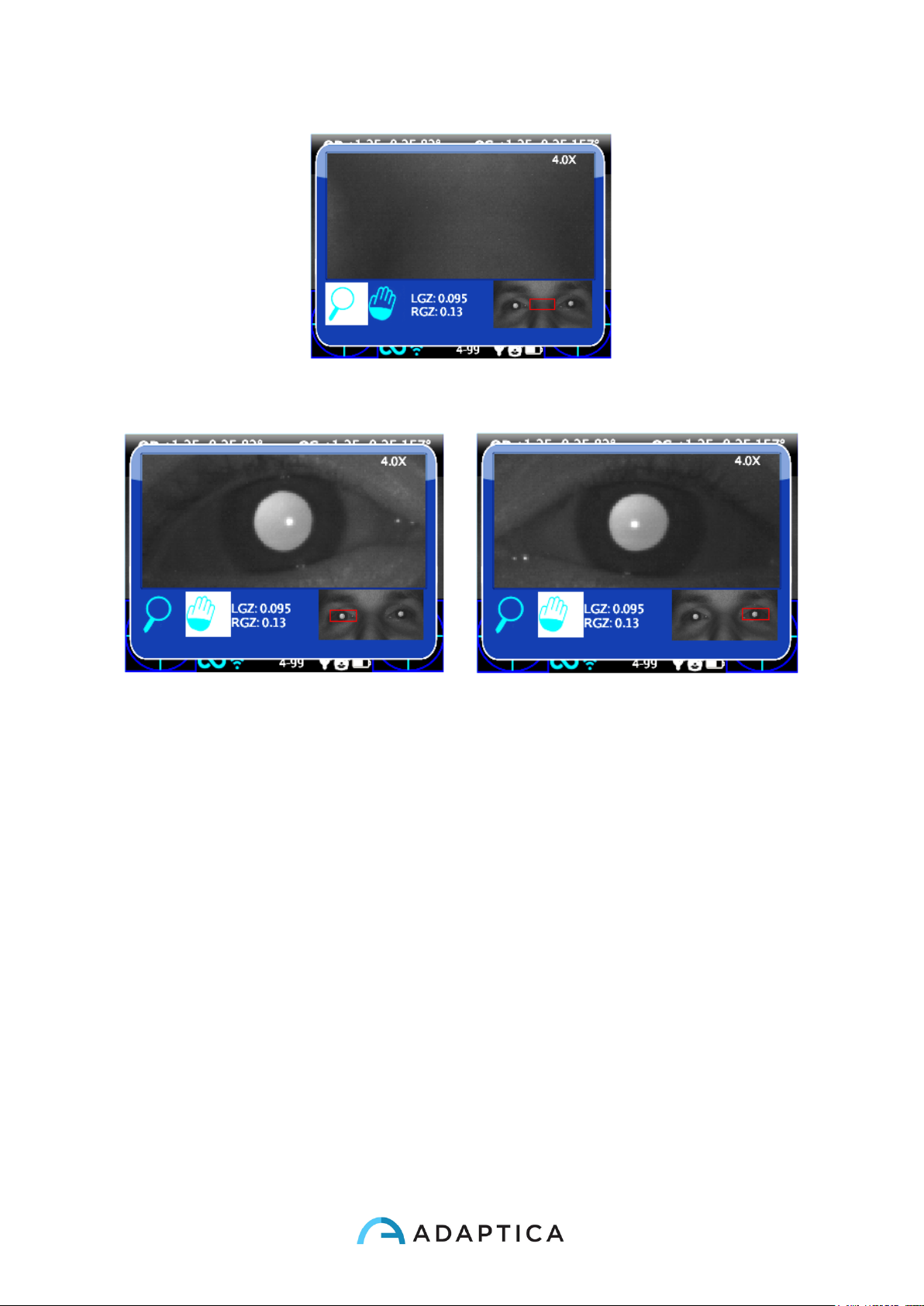
The Zoom App has two main functions on the bottom left of the screen: the Zoom function
(lens) and the Pan function (hand). The function in use is indicated with a lighter square.
You can change function by pressing the central button of the joystick or by the
sound/attention lights button (Button D) .
In normal condition the Zoom frame will automatically get in position (clicking on print button from the main result window) on the left pupil zoomed to the maximum (4x). If it
couldn’t identify the pupils (failure measurement or measurement done without Zoom function) maybe the pupils haven’t been identified and in this case the Zoom will get in position
on the center of the image
The zoom function indicated by the magnifying glass is the function that allows you to
increase or decrease the zoom power on the image by the up or down buttons from a
maximum of 4x to a mimimum of 1x.The steps are 0.2x each.
Page 43
43
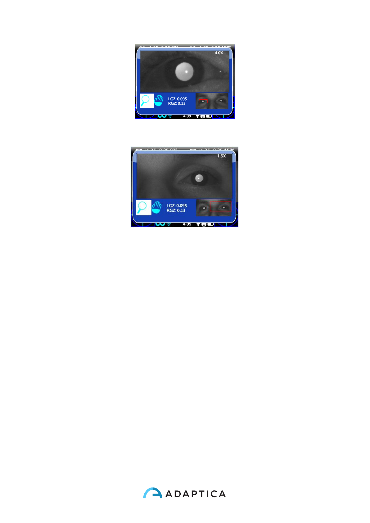
If you hold the down button the zoom will became 1x, if you hold the up button the zoom
will became 4x centered on the selected pupil.
If you want to change pupil you have to press the right and the left buttons that allows you
to choose on wich of the two pupils the zoom will take place.
You can center and zoom another image detail by selecting it with the Pan function and
then adjusting the zoom power by the up and down buttons.
The zoom function centers automatically the selected pupil but in case of changing
to the Pan function the zoom will leave the the pupil center and the system will point
to the new position selected by the PAN function.To return to the automatic zooming
on the pupil you have to press one of the right and left buttons.
Pan Function
The pan function allows you to locate any detail of the image. After selecting it, you have to
use the arrow buttons to browse in the image. For a rapid movement you have to hold the
arrow (joystick) button to the direction you want. After positioning on the detail you can
change the function to choose the zoom power you want by the up and down buttons
without losing the center of the image.
Page 44
44
How to activate zoom on other measures
You can use the Zoom App on an image took from another measure by selecting the Zoom
function and loading the image.
The Zoom App sometimes does not automatically identify the pupils.
Auto-research of pupils
In case of automatically identifing of the pupils, the situation will be the same as the normal
situation shown earlier. You can try to change pupil to confirm that both pupils have been
identified. If it doesn’t work, the zoom window will automatically get in position on the right
pupil and that means it has identified only one of them. If the zoom will get in position on
the center of the image it means that none pupil has been identified in the image and you
have to go forward with the manual positioning.
Manual research of pupils
If the zoom will get in position on the center of the image (if the pupils haven’t been recog-
nized or you used a measuring without Zoom App)
Page 45
45
you can position the pupils by the pan function and then save their positions after reaching
it by pressing the pupil button to memorize its position, both right and left.
After selecting the two pupils you have to return to the main screen by clicking the power
button and then you can save the exam and the pupils position by holding the print button.
Once the new position has been saved you just need to reload the new exam from the SD
memory to use the Zoom App again
Menu
Through the menu it is possible to configure all the features and the working modes of the
device.
The menu is activated by pressing the centre of the cross button. To exit the menu press
left on the main menu page.
Page 46
46
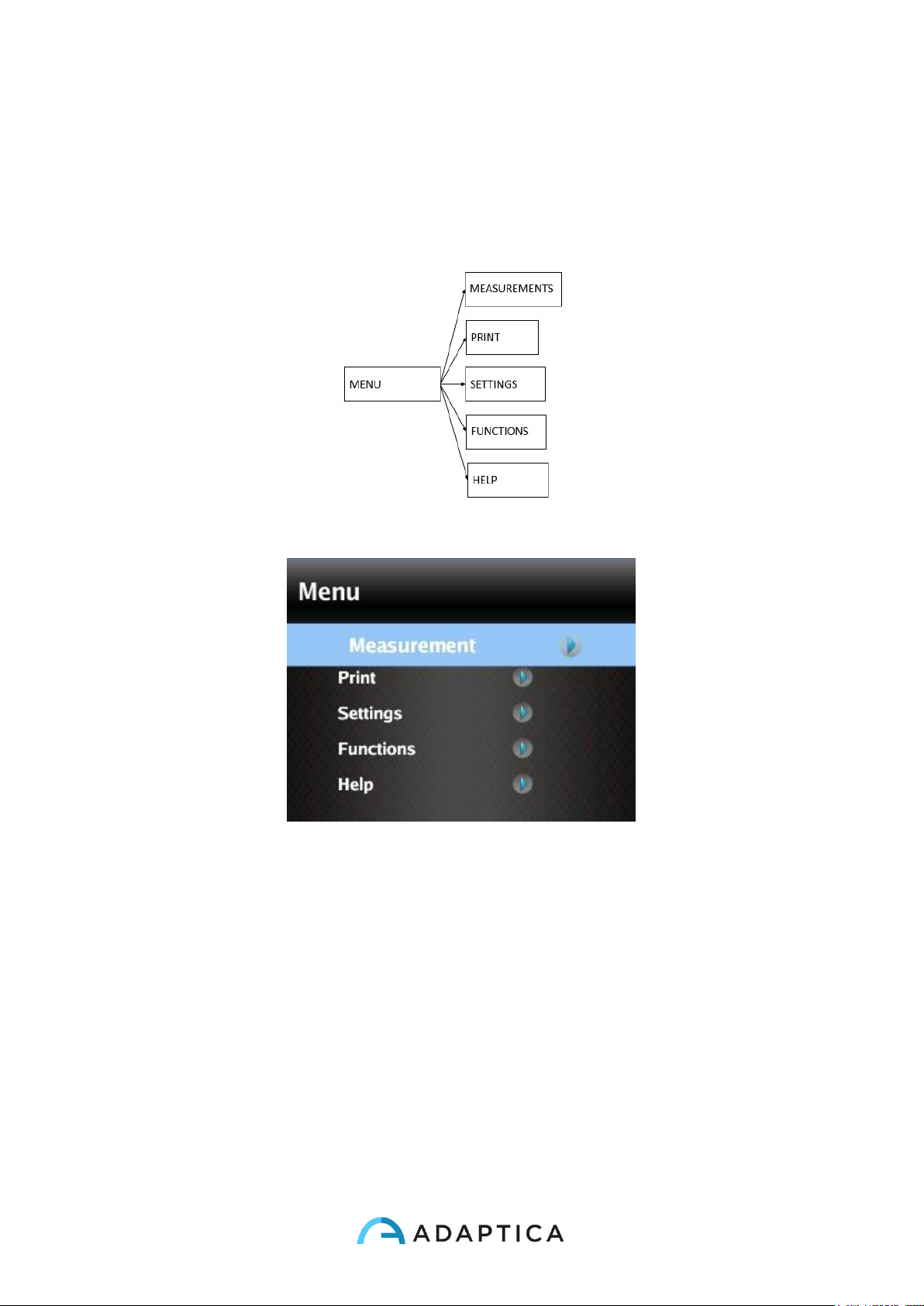
To navigate on the menu use the arrows on the cross button:
UP and DOWN buttons will move up and down the highlighted choice, RIGHT button will
select the highlighted choice navigating deeper by one level in the menu, LEFT button will
step back to previous menu level towards main menu page.
Main menu page is schematized in the following picture,
while this is how the display will appear entering the menu:
The first level menu entries are described in the following paragraphs.
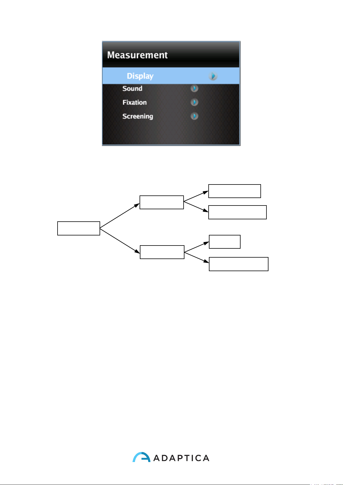
• The submenu Measurement collects the settings related to the examination:
Page 47
47
• The submenu Display allows to change the way results are presented on the
display.
Refraction: allows choice between plus and minus cylinder visualization. Once the
measure is displayed, it is still possible to toggle between the two visualization modes by
pressing the UP arrow on the cross button.
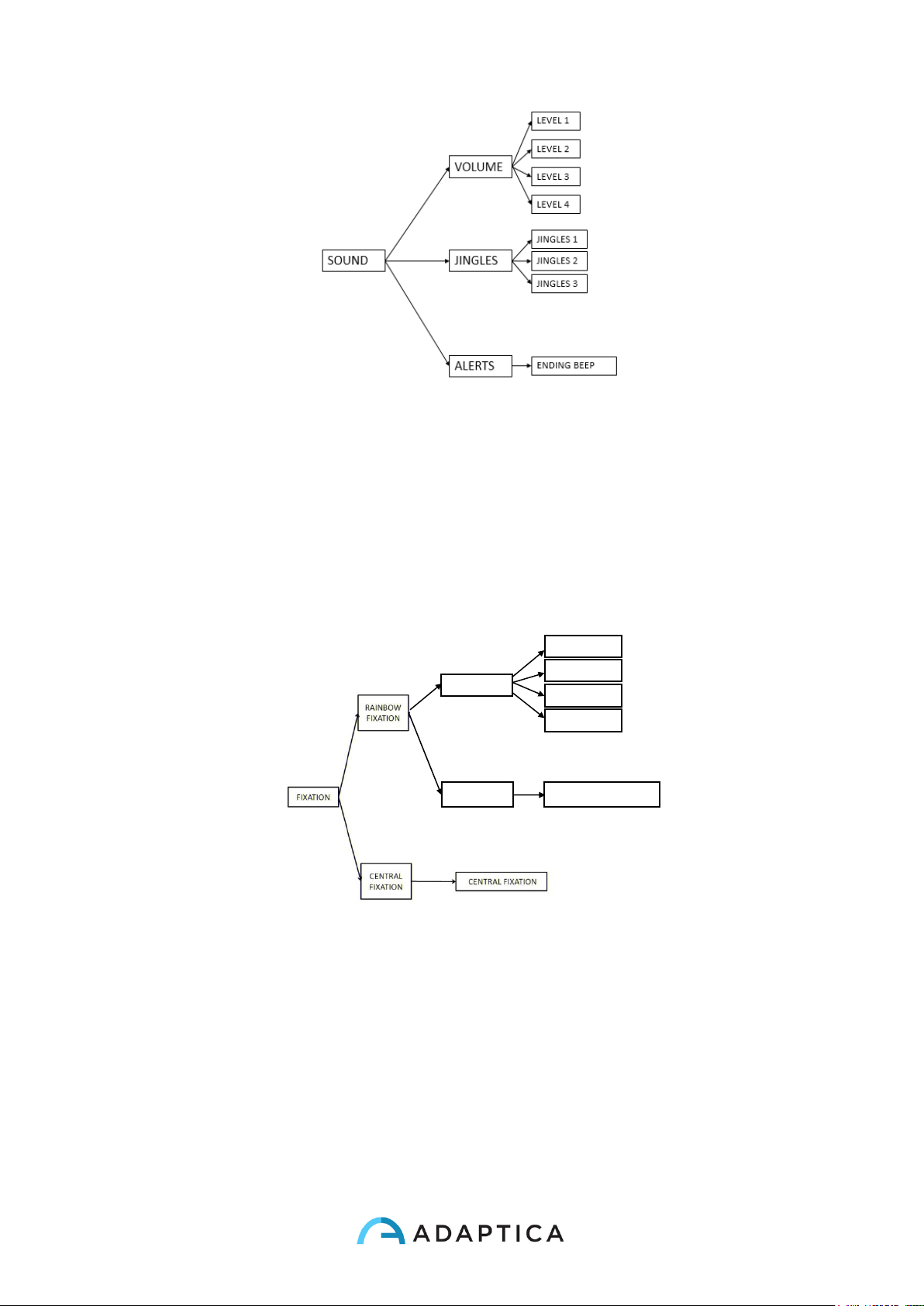
• The submenu Sound configures the interactivity sound. It consists of three items:
Volume, Jingle and Alerts.
DISPLAY
REFRACTION
GAZE
PLUS CYLINDER
MINUS CYLINDER
DEGREE
HIRSCHBERG TEST
Page 48
48
Volume: sets audio power output for the interactivity sound, within a range of four levels.
Jingle: allows to choose the Jingle for the interactivity sound, out of three available
melodies.
Alerts: allows to activate the ending beep at the end of the measurement.
• The submenu Fixation configures the interactivity light.
Most of the items in the submenu Rainbow Fixation are self-explanatory. They are
different ways of turning on the visible led in front of the 2WIN. Custom sequence is to be
configured by placing a proper custom file in the SD card. See the Customization
paragraph for details
Selecting Central Fixation, and then toggling ON the item Central Fixation, will enable a
visible central fixation light, as an help to patient's attention.
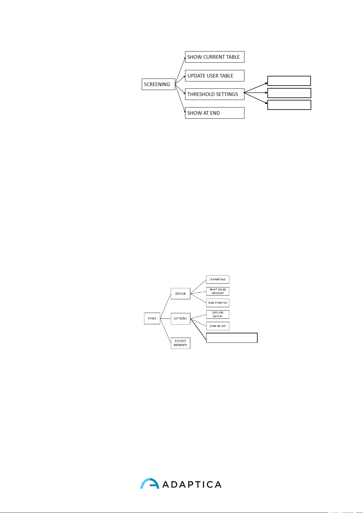
• In the submenu Screening, 'ShowCurrentTable' displays the current Screening
table, either the default table or the one compiled by the user.
INTENSITY
INTENSITY 2
INTENSITY 3
INTENSITY 4
INTENSITY 1
SEQUENCE
CUSTOM SEQUENCE
Page 49
49
•
'Update User Table' is selected when uploading a user table, and for uploading a
newly compiled user table.
‘Threshold Settings’: (a) Screen Min Axis: you are measuring with a notation that
minimize the sphere –this mode is independent by how the data is displayed; (b)
Screen Max Axis: you are measuring using a notation that maximize the sphere sphere –this mode is independent by how the data is displayed; (c) Screen
Displayed: you are measuring what you see on screen - this mode is dependent by
how the data is displayed;
'Show at end' displays the auxiliary window of relative application at the end of
measurement automatically.
• The submenu Print (see section “PRINT” in the following) allows to select the
Device, configuring the exam printout to printer and/or to file. Please check the
Printing paragraph for details.
IR Printing: enables/disables printing through IrDA to portable printer.
Print on SD memory: enables/disables saving the exam onto SD card.
Mail Printing: enables/disables Mail Printing service.
Grid on Report: enables/disables overlay of a grid on the exam report saved onto the SD
card.
Strip in Pdf: enables/disables the saving of a pdf file similar to the IrDa strip.
Print screening on IRDA: enables/disables printing the full exam through IrDA to portable
printer
SCREEN DISPLAYED
SCREEN MAX AXIS
SCREEN MIN AXIS
PRINT SCREENING ON IRDA
Page 50
50
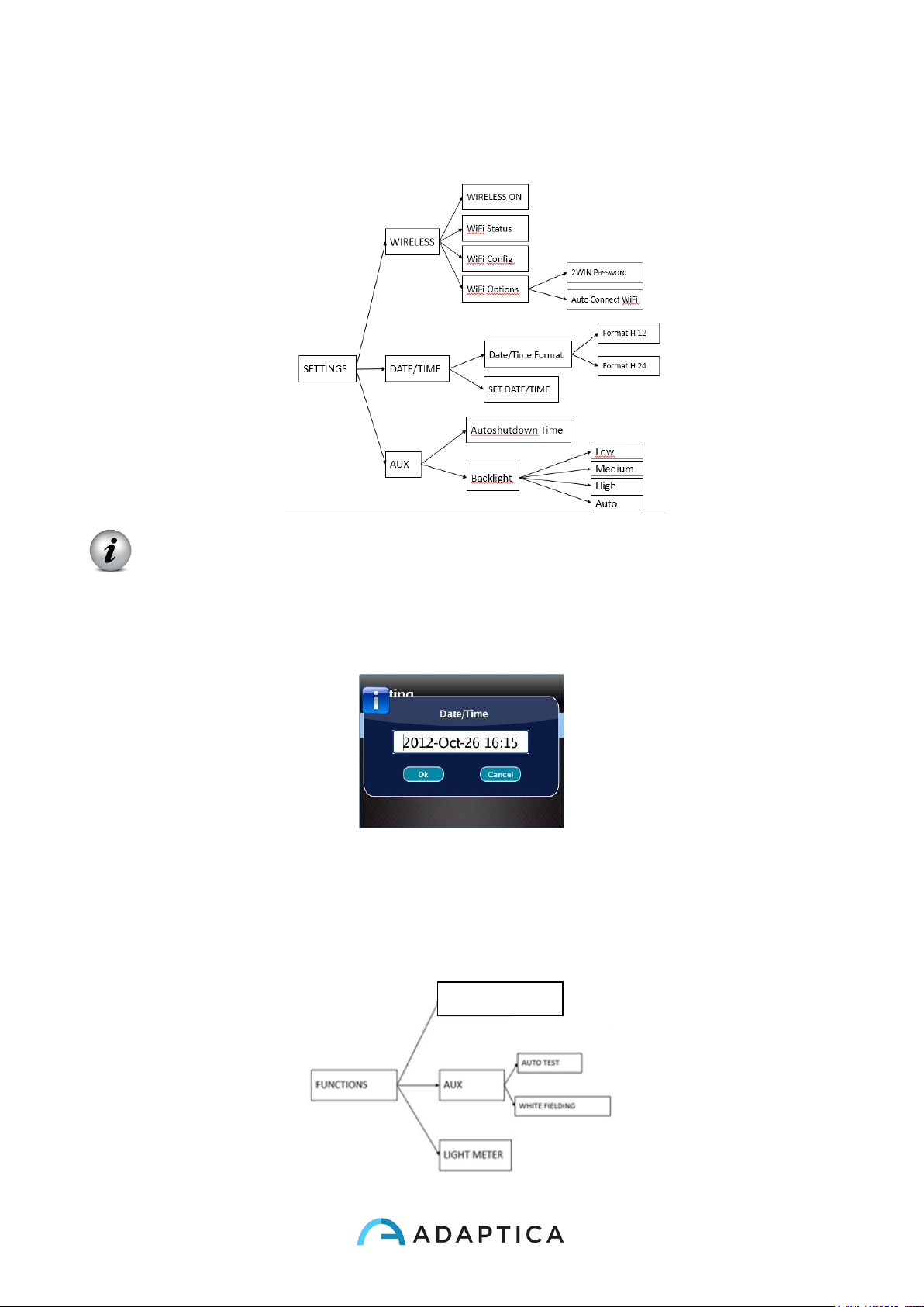
• The menu Settings configures three more features:
Wireless (optional, this item is visible only in devices with the WiFi module
installed) is described in chapter 9.
Date/Time:
Date/Time Format allows to choose between H12 or H24 format.
Set Date/Time allows to set current date and time.
AUX: Autoshutdown sets the autoshutdown timing. Backlight sets the LCD display
backlight intensity, either between low, medium and high levels, or enabling automatic light
dimming, driven by an ambient light sensor. Please notice that the brighter the display, the
faster the battery gets discharged.
The menu Functions configures three feature:
2WIN APPLICATIONS
Page 51
51
From this menu it is possible to activate 2WIN Applications. This functions is
described in chapter 9.
AUX: Auto test allows to make a self hardware test of the device.
White Fielding will enable, on next measurement, a device verification test called white
fielding. See the related paragraph.
Light Meter enables an evaluation of the ambient light.
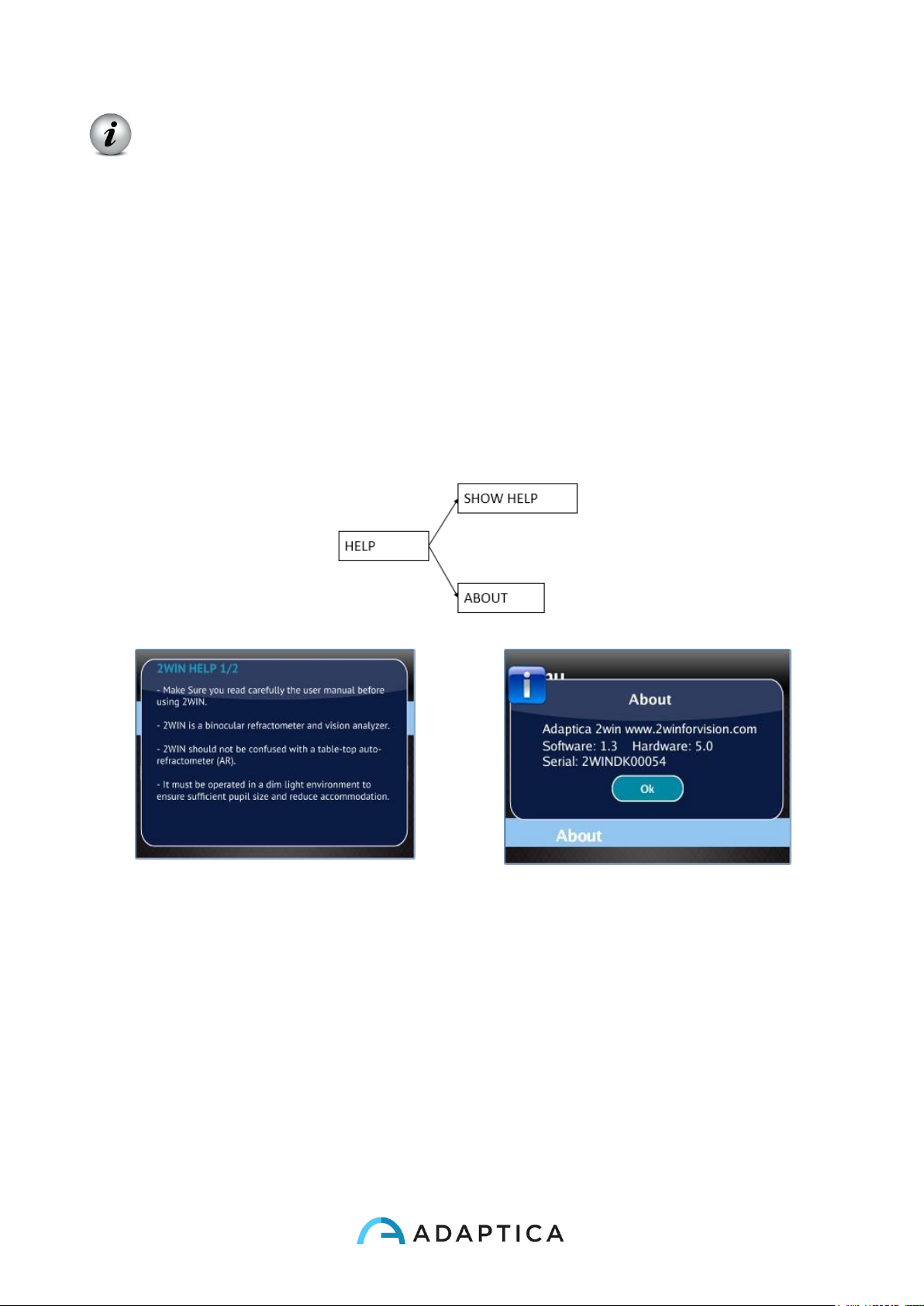
In the Help submenu, it is possible to select the Help page and the menu item About
shows information about the device, such as the software version and the hardware
version.
• In the Help submenu, it is possible to select the page of Help / Help, while the item
About / Info displays information about the device, such as the software version and
the firmware version.
First page of help
About’ message
Those information should be used for the reporting abnormalities to your distributor.
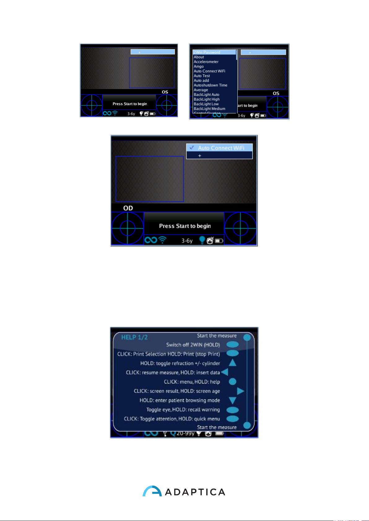
Quick menu
In order to get access to the preferred and most used functions of the 2WIN, it is possible
to activate the Quick Menu. With this Menu is possible to recall rapidly any 2WIN
function/item that is commonly used by the operator. It is enabled by keeping pressed
button D. The Quick Menu items appears top right, the '+' button allows to add new items
(all items from the main menu can be added by pressing the central button) to the quick
menu. Items can be erased and moved pressing long the left arrow.
Page 52
52
How to add an item in the quick-menu.
Possible configuration of the quick-menu.
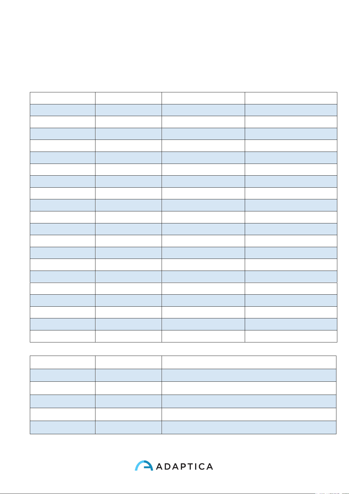
Contextual Help
At any time, holding the menu button, an help page is shown if the page provides one.
Pages with the help option are: Main/Home, Menu, Keyboard, Age Selection, Browsing
Mode, Data and Time Modification.
Example of contextual help. Note that the two light blue circle at the top and at the bottom of the window represent the two frontal
START buttons, while the other symbols all the 2WIN backside butto
Page 53
53
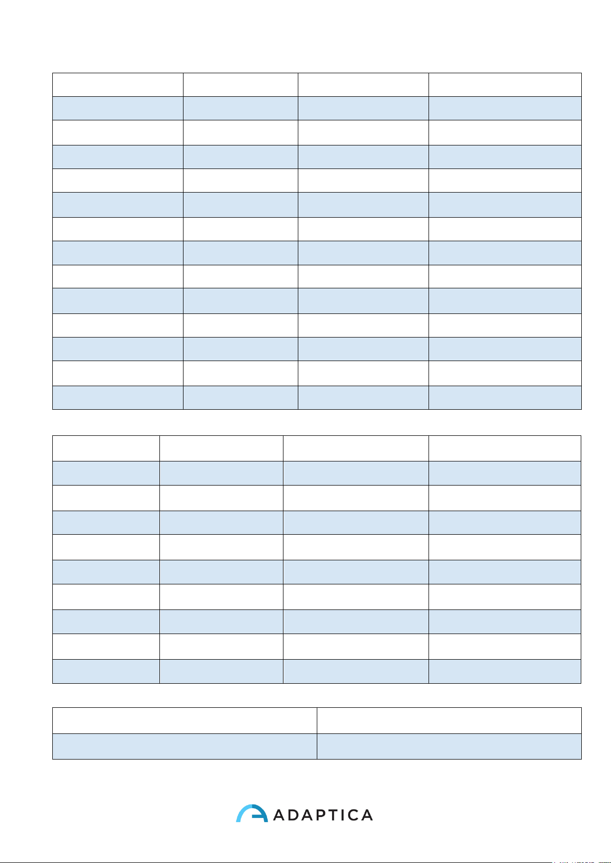
Summary of menu entries
1.0 Measurement
1.1 Display
1.1.1 Refraction
1.1.1.1 Plus Cylinder
1.1.1.2 Minus Cylinder
1.1.2 Gaze
1.1.2.1 Degrees
1.1.2.2 Hirschberg Test
1.2 Sound
1.2.1 Volume
1.2.1.1 Level 1
1.2.1.2 Level 2
1.2.1.3 Level 3
1.2.1.4 Level 4
1.2.2 Jingles
1.2.2.1 Jingle 1
1.2.2.2 Jingle 2
1.2.2.3 Jingle 3
1.2.3 Alerts
1.2.3.1 Ending Beep
1.3 Fixation
1.3.1 Rainbow Fixation
1.3.1.1 Intensity
1.3.1.2 Sequence
1.3.2 Central Fixation
1.3.2.1 Central Fixation
1.4 Screening
1.4.1 Show Current Table
1.4.2 Update User Table
1.4.3 Threshold Settings
1.4.3.1 Screen Displayed
1.4.3.2 Screen Max Axis
1.4.3.3 Screen Min Axis
1.4.4 Show At End
2.0 Print
2.1 Device
2.1.1 IR Printing
2.1.2 Print on SD memory
2.2 Options
2.2.1 Grid on Report
2.2.2 Strip in PDF
2.2.3 Print Screening on IRDA
2.3 Export Patients
Page 54
54
3.0 Settings
3.1 Wireless
3.1.1 Wireless ON
3.1.2 WiFi Status
3.1.3 WiFi Config
3.1.4 WiFi Options
3.1.4.1 2WIN Password
3.1.4.2 Auto Connect WiFi
3.1.5 Connections
3.1.5.1 VisionFit Connection
3.2 Date/Time
3.2.1 Date/Time Format
3.2.1.1 Format H12
3.2.1.2 Format H24
3.2.2 Set Date/Time
3.3 Aux
3.3.1 Autoshutdown Time
3.3.2 BackLight
3.3.2.1 Low
3.3.2.2 Medium
3.3.2.3 High
3.3.2.4 Auto
4.0 Functions
4.1 2WIN Applications
4.1.1 Corneal Reflexes
4.1.1.1 Corneal Reflexes
4.1.1.2 Reset
4.1.1.3 Options
4.1.2 Intermediate Vision
4.1.2.1 Intermediate Vision
4.1.3 Lens Centering
4.1.3.1 Lens Centering
4.1.4 Dynamic Pupillometry
4.1.4.1 Dynamic Pupillometry
4.1.5 Zoom
4.1.5.1 Zoom
4.2 Aux
4.2.1 Auto Test
4.2.2 White Fielding
4.3 Light Meter
5.0 Help
5.1 Show Help
5.2 About
Page 55
55
Print to portable infrared printers
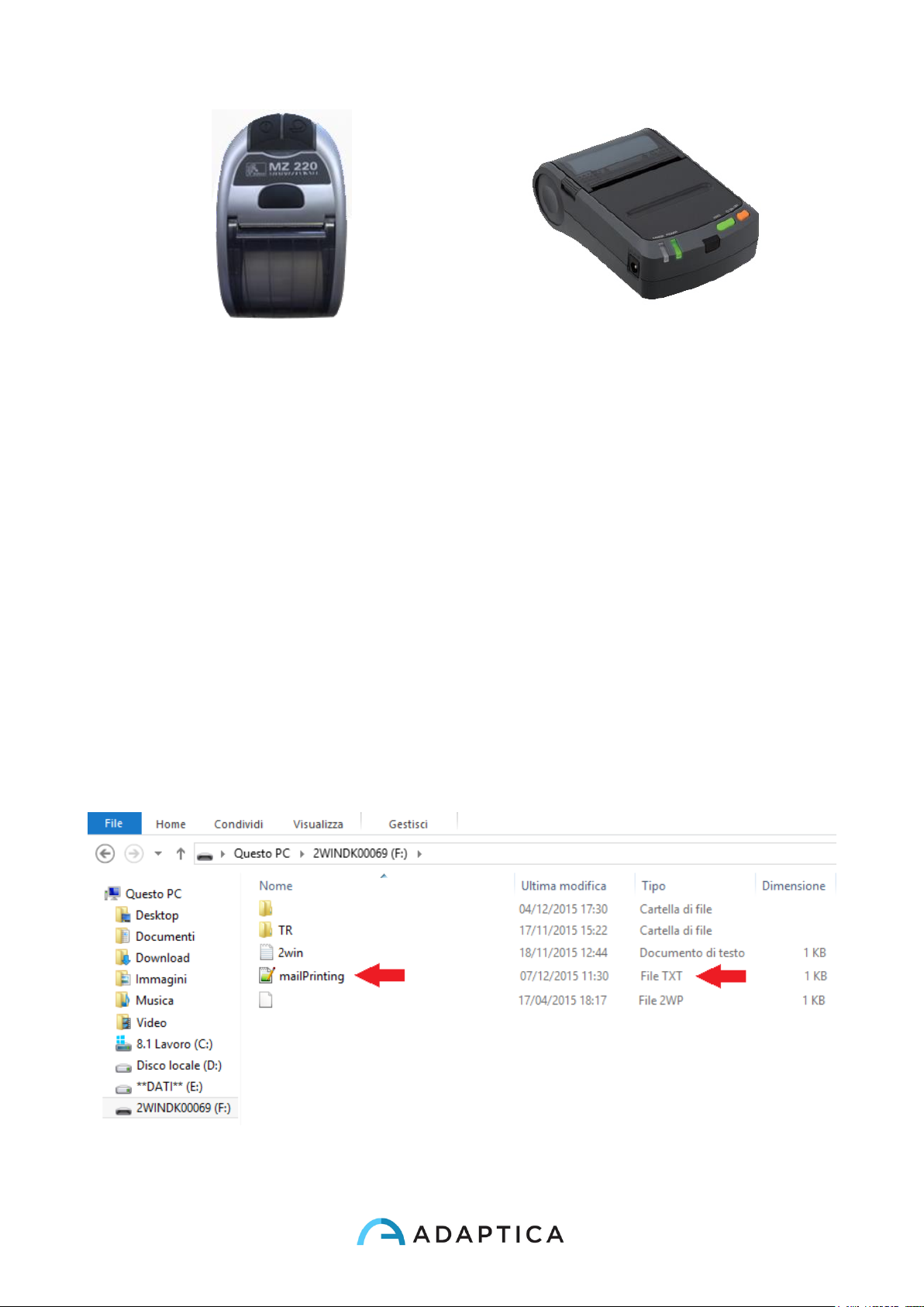
2WIN is compatible with three specific battery operated printers:
1) Manufacturer GEBE – Model 11898 GPT-4378-Flash-79-V.24-IrDA
a. Compatible with 2WIN software version greater than 4.1.161213
b. If bought from Adaptica the printers works out of the box while if the operator
will buy in a different moment, the printer must be configured. See Appendix
B.
2) Manufacturer SEIKO – Model dpu-s_245
a. Compatible with 2WIN software version greater than 4.1.161213
b. If bought from Adaptica the printers works out of the box while if the operator
will buy in a different moment, the printer must be configured. See Appendix
B.
3) Manufacturer ZEBRA – Model MZ220-it
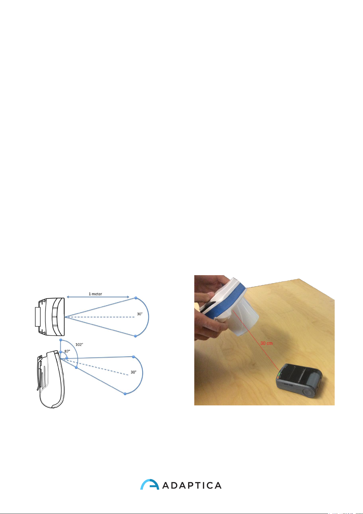
In order to print or to save the data press BUTTON B, once the measurement is done. If
you want to print via the external optional portable IrDA (Infrared Data Association) printer,
remember to point the machine towards the printer according to the following diagram
before pressing the button.
IrDA Printing positioning
Page 56
56
IrDA portable printers
You can print the same exam as many times as needed.
When printing to IrDA printer, the data transmission can be interrupted and aborted by
keeping the BUTTON B pressed for 1 second.
Mail Printing
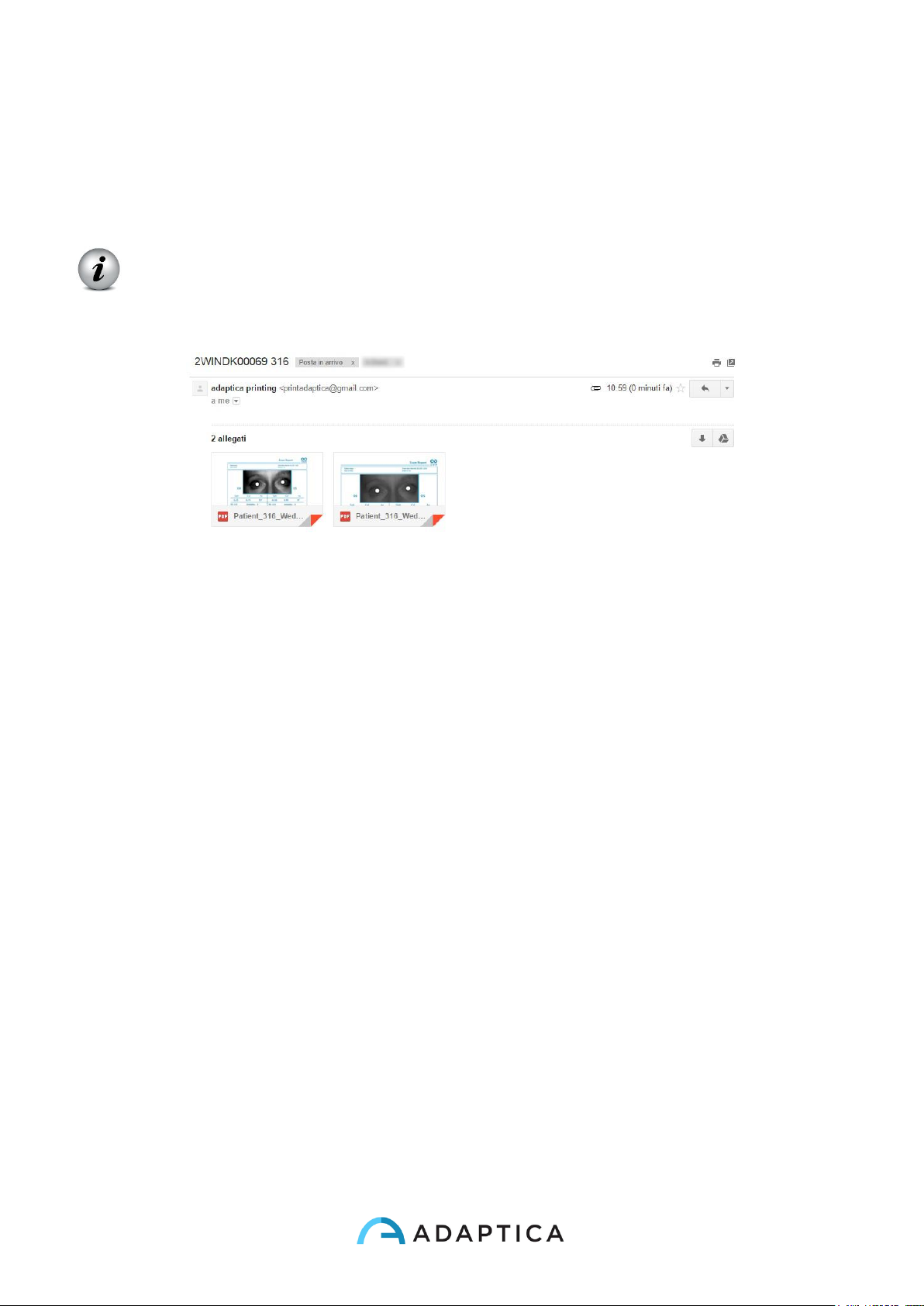
It is possible to send a mail with 2WIN pdf attachment in order to allow mail printing from
2WIN or to receive via email the measurement. In order to activate this service, place a file
(*.txt file) named mailPrinting in the SD root containing the email you want the files to
be sent to (ex. [email protected]).
2WIN Applications
2WIN Exams2
Page 57
57
Reboot the machine and a new menu item will appear under Menu>Print>Device>Mail
Printing. If checked, after the pression of Button B, an email will be sent automatically to
the specified address with attachments. The email can be a personal email or a printer
email. The email service used for email sending is Gmail.
NOTE: Remember to activate WiFi and to be connected to a WiFi network to use
Mail Printing service. If not activated, mail will not be delivered.
Ex. Mail printing
Save exam
If the SD card printing is inserted, a set of 4 files for each examination will be saved into
the SD card, into the folder Patients (“2WIN Exams” if the software version is the 4.0 or
more), there creating a subfolder named 2WINExam _date_number, where date is current
date and number is a sequential number. The same number will be mentioned in the
“Printing: done” message, so enabling the user to connect the examination to the specific
patient.
The subfolder will contain at least 4 file, with the same name as the folder, but different
extensions:
*.pdf = examination results form for a A4 size paper (printable from a personal
computer), other pdf can be written by specific functions.
*.jpg = original picture of the eyes of the patient
*.xml = xml file version of the measurement results
*.2win = binary file (for service purposes only)
For data saved in pdf format., a grid on exam report can be added selecting the option
'Grid on Report' from Menu Print/Options/Grid on Menu.
Page 58
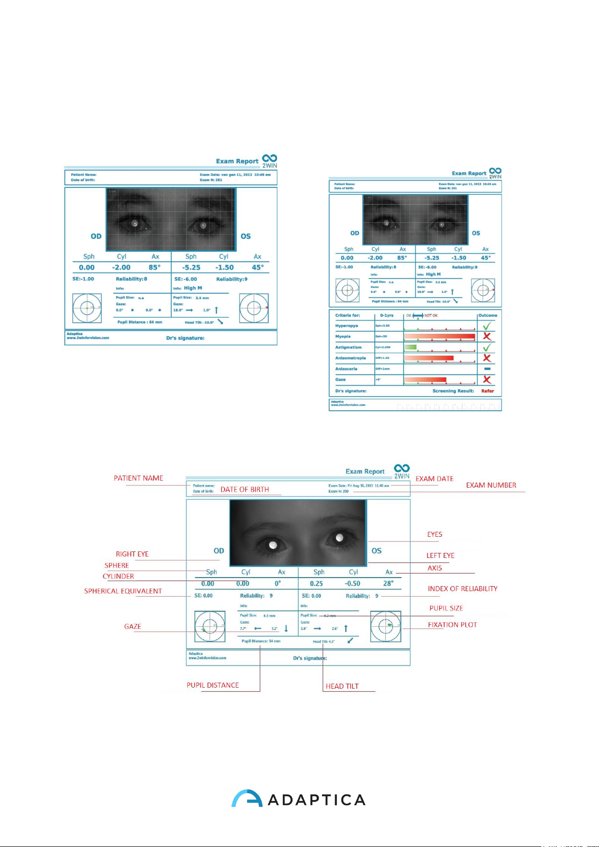
58
An example of the exam report in .pdf
(with Grid on Report option) is shown in
the following Figure
An example of the extended exam
report for screening in .pdf (with Grid on
Report option) is shown in the following
Figure
Exam report in .pdf
Page 59
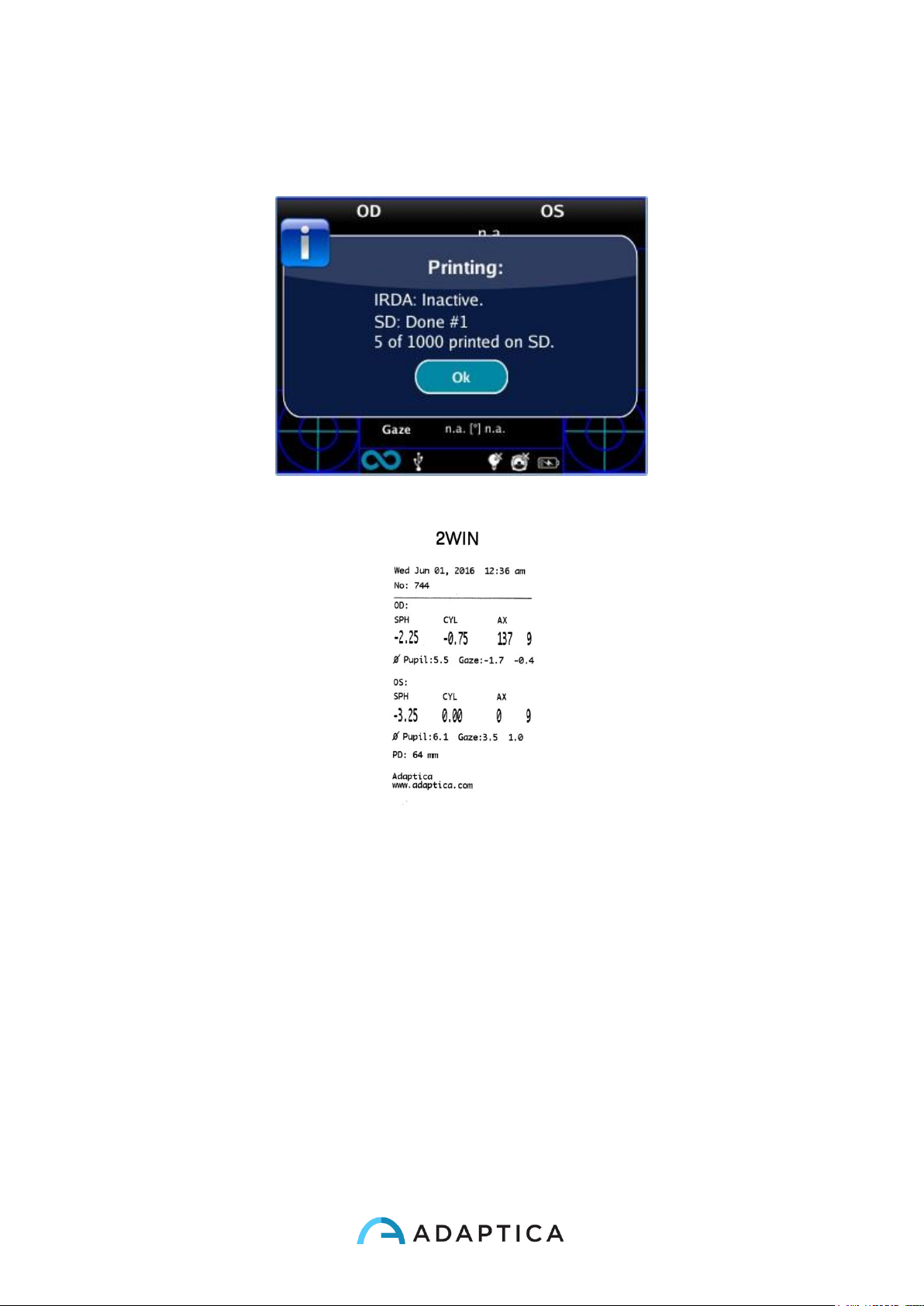
59
There are a limited number of prints before the machine starts rewriting oldest files. When
printing, Printing: done” message will also show the internal memory total exam capacity
(1000 patients).
“Printing: done” message
Printout sample from portable IrDA printer
Data saved in the file Patient_date_number, with the different extensions listed above, can
be extracted from the SD card by connecting the 2WIN to a PC by means of the USB
cable supplied. The 2WIN is seen as an external memory storage, when the USB symbol
appears on the 2WIN display it is possible to copy data from the 2WIN SD card to the PC.
It is important to safely remove (unmount, check the PC Operative System for this) the
external memory storage of the 2WIN from the PC after data have been saved on PC and
before disconnecting the USB cable.
Page 60
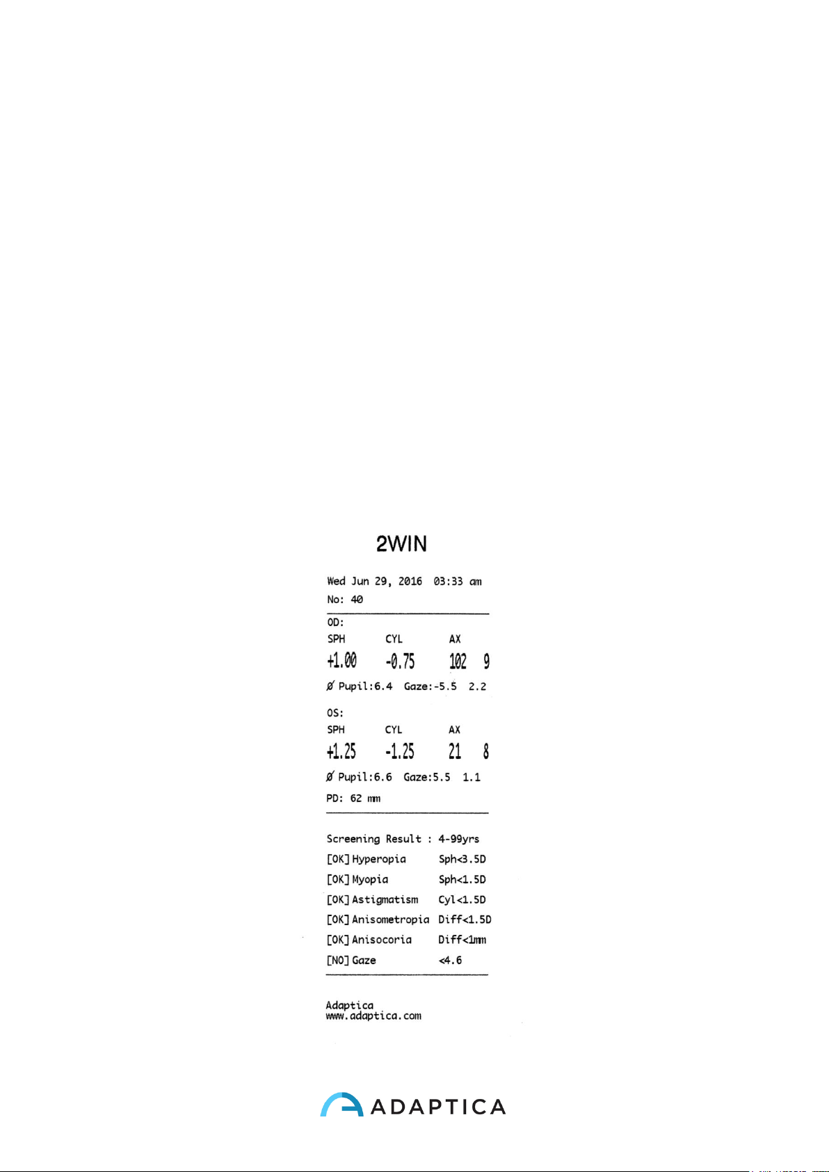
60
Print screening on IRDA
Page 61
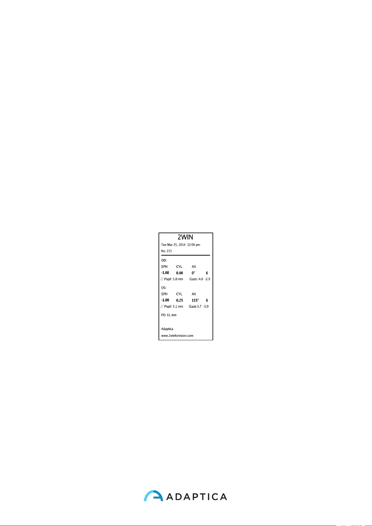
61
This option allows you to print a paper screening report. To activate it:
Menu>Print>Options>Print screening on IRDA
Strip in Pdf
This options allows the creation of a strip similar to the IrDa strip in pdf format. It can be
enabled from Menu>Print>Options>Strip in Pdf.
CVS Exporter Tool
The 2WIN permits to export all the patient data stored in the SD card in a CVS (Comma
Separated Value) file. This text-based file can be used to share data from 2WIN and
spreadsheet documents.
Select “Export Patient” from Menu>Print
Page 62
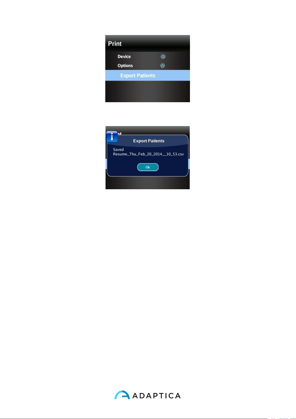
62
Once activated the export patient, the 2WIN will create in the root of the SD memory card
the CVS file with the following name-format: Resume_Date_Hour.
Gaze
The maps indicate the gaze (that is the eye position), not the corneal reflex. The eye
position is calculated on the base of corneal reflex position compensated because the light
is not centered, and the direction of eye movement is opposite compared to movement of
reflex.
The Gaze information on the refraction module shows the displacement of visual axis on
respect to the pupil center. This displacement can be a strabismus factor but it normally
corresponds to the K angle.
This indication on refraction module for a correct diagnosis must be confirmed with the CR
application. In this case the software application is able to determine deviation as an angle
K and as the true strabismus, comparing the binocular fixation with the fixation of a single
eye (right and left).
The CR package shows Angle K (not the gaze) and Tropia / Foria because we can have a
complete measure using the 3 exams (binocular, left and right)
You can find in the 2 exams where a "tropia" and a "foria" are detected.
The CR package is the only type of exam able to verify and calculate the strabismus
information.
Page 63
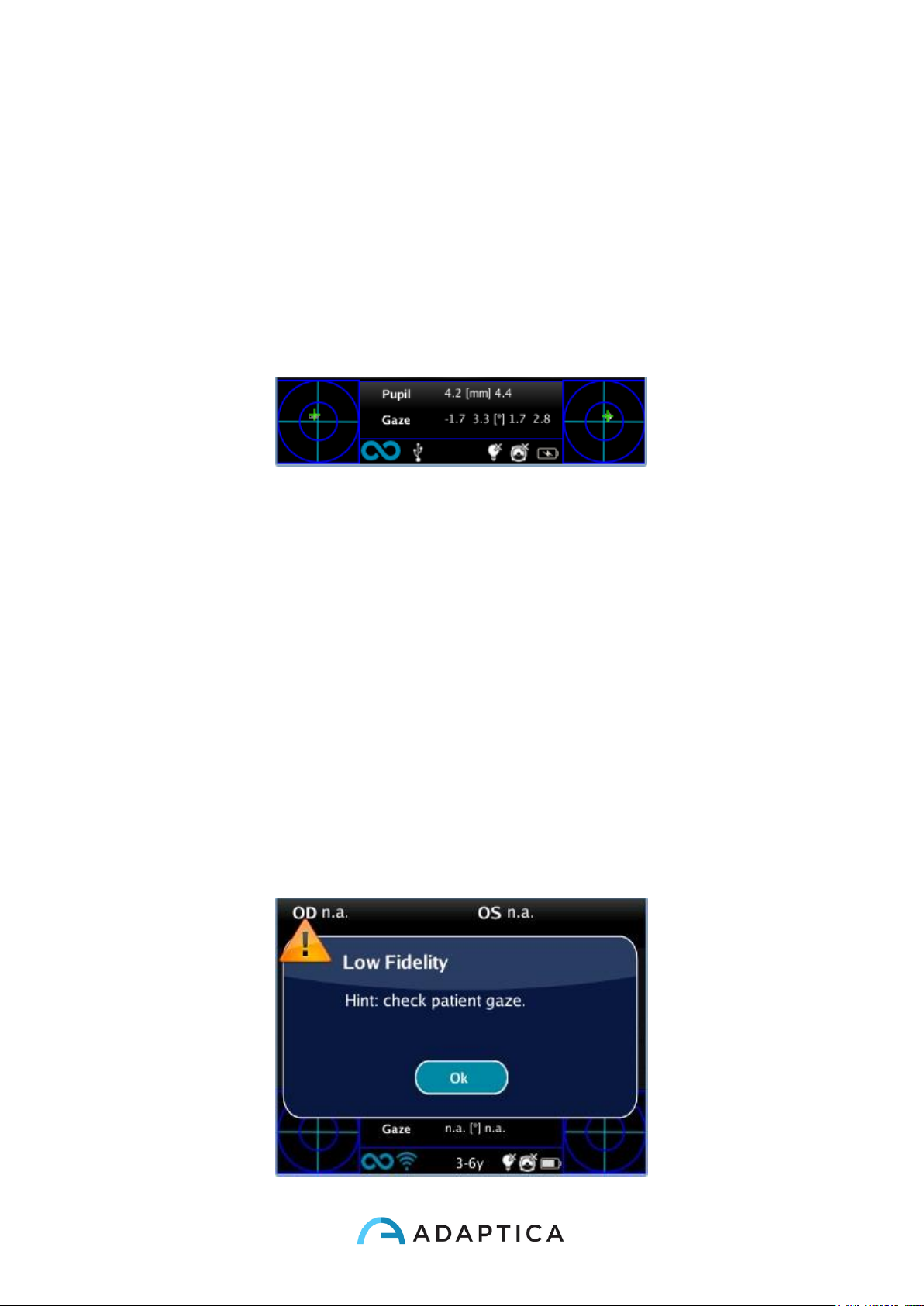
63
In the images you can see the position of eye on maps, and you can easily understand
how Tropia is evidenced simply comparing position in binocular (first line) respect a cover
test (under). During cover test, the only eye the patient are using is fixating perfectly. On
the binocular vision can happens that one eye is not fixating.
Foria is detected comparing position under cover test (position of eye covered) compared
to binocular vision eye position.
The Gaze direction is measured as the distance between the corneal reflex and the
geometric center of the pupil.
Please consider that the corneal reflex is represented on the graph in an inverted position:
if the corneal reflex is nasal to the center, it is represented as temporal in the diagram
time.
The direction of gaze as measured by this tool is not directly related to the measurement in
cover test.
It is a graphical representation that suggests the presence of orthotropia, exo/eso tropia,
hyper/hypo tropia and stability or instability of fixation.
Range: +/-20°;
Out of range:+/- 10° refraction is not displayed (fixation error)
Resolution: 0.1°
The precision is (0.2°) on a standard eye with a corneal radius of 7.75 mm (The value is
calculated on the standard corneal radius, which is assumed to be 7.75 mm).
If a patient doesn’t focus on the central front led a warning will appear on the display:
Page 64
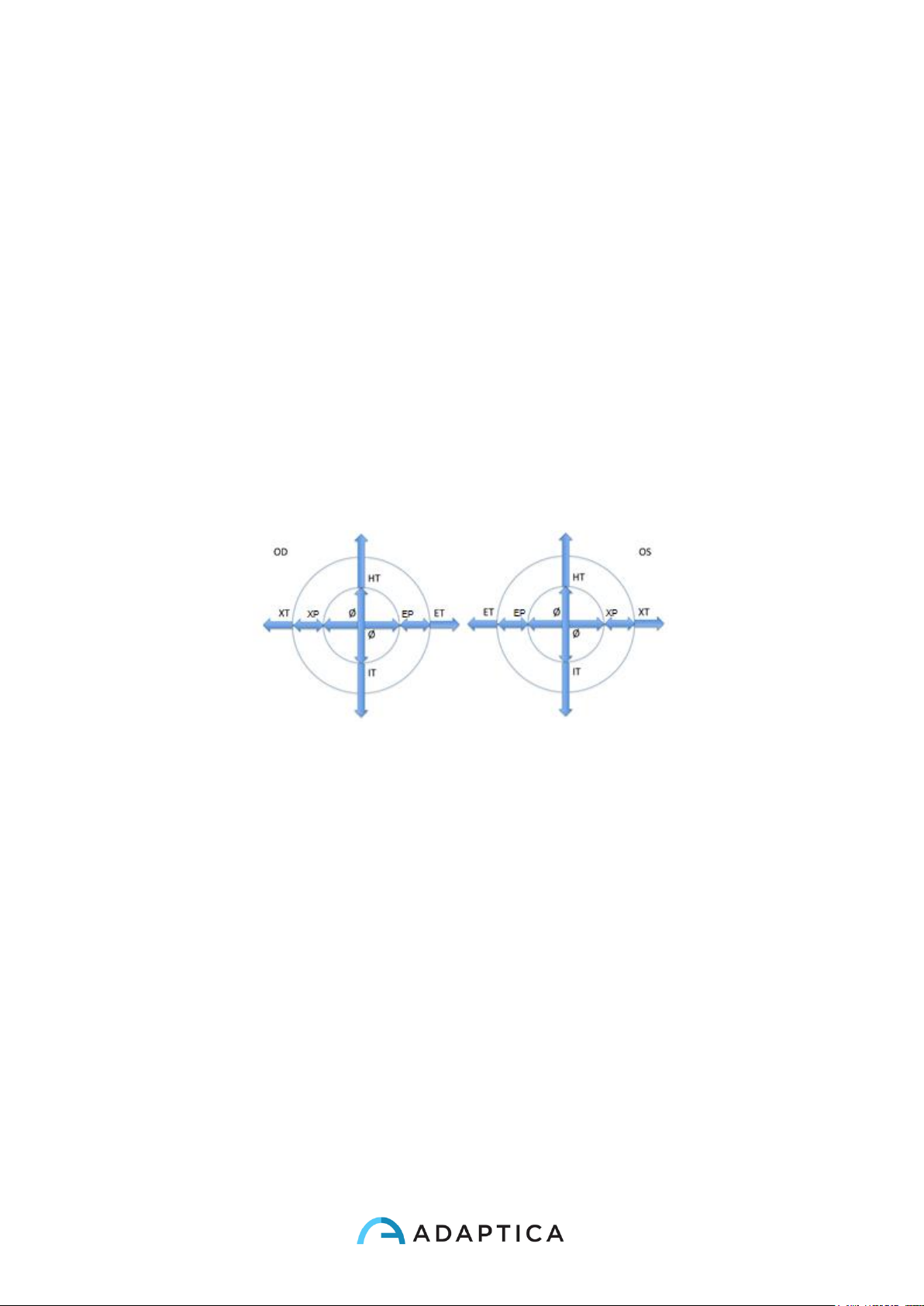
64
Low fidelity message
Hirschberg Test
If “Hirschberg test” is selected for the representation of the gaze, either in the MENU or by
toggling the visualization type via cross button (DOWN arrow), the results for patient's
fixation will be expressed by the Hirschberg test coding:
ET = esotropia
EP = esophoria
HT = ipertropia
IT = ipotropia
XP = exophoria
XT = exotropia
O = ortotropia
The following picture gives a graphical representation of the codes.
Customization
Some features of the device can be customized by the user. To do this the user shall take
the SD card out of the device, write it by means of a personal computer, then reinsert it in
the device.
Please notice that in order to extract and insert the SD card, the device shall be OFF.
Custom printouts
By creating in the root folder of the SD card a file named
printoutPersonalData.txt
Page 65
65
printouts (both to portable printer and to file) will be customized by adding the first three
lines contained in such file.
Sample:
Winning Eye Clinic
5, Trafalgar Sq. London
www.winningeye.com
NOTE: The text file must be saved in UTF-8 codification from your text editor.
Custom RGB sequence
By creating in the root folder of the SD card a file named
rgbCustomSequence.txt
and enabling custom sequences in the menu, the interactivity light can be personalized.
The file shall contain 30 or less rows (exceeding rows will be ignored) coded as follows:
each row contains 4 numbers
• first number must be in the range 0-5 and codes the mode:
0=off
1=rotating rgb
2=fixed white
3=rotating black on blue
4=fixed green
5=flashing red
• second number is a parameter in the range 50-1000: for modes 1 and 3 it represents
the delay, that is the reciprocal of rotational speed
• third number is the intensity, in the range 0-255
• fourth number is the duration (of the mode described by the line), in the range 1-30
For example:
1 100 10 2
0 0 0 1
4 0 15 1
3 500 20 2
3 200 10 2
will perform:
2 seconds rotating with a 100ms delay and intensity 10
Page 66
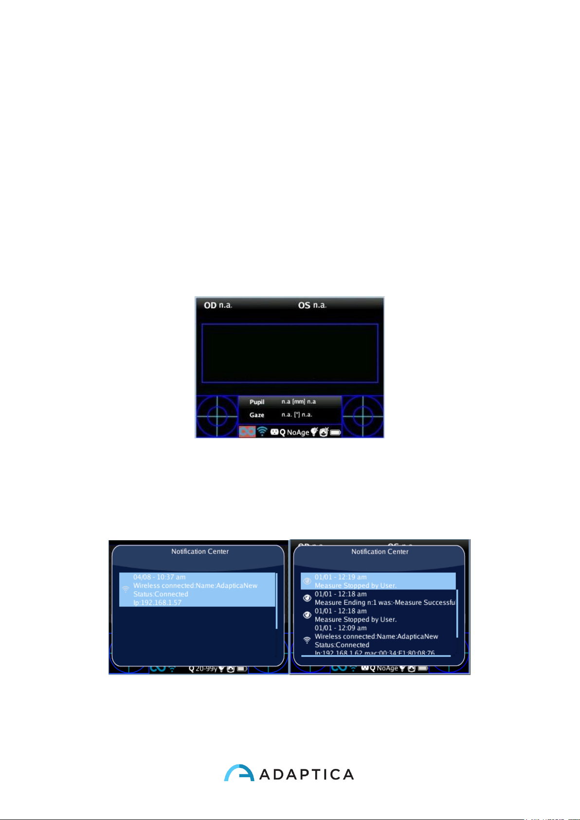
66
1 second OFF
1 second fixed green with intensity 15
2 seconds black rotating on blue with a 500ms delay and intensity 20
2 seconds black rotating on blue with a 200ms delay and intensity 10
Notification Center
This feature allows the real time monitoring of 2WIN messaging and logs. There are
reported 3 different types of information: notifications on the measurements, notifications
on the WiFi networking status and logins and notifications on the additional software
Applications installed.
When a new notification is added to Notification Center, 2WIN logo will be shown with a
red background.
The notifications are stored in the Notification Center in a recursively way, the last 20
information are always showed.
In order to see the Notification Center press and hold the “eye” button, you can then
consult the list of notifications. In order to exit from the center just press the “esc/Power”
button.
Screening Mode
Page 67

67
If date of birth is not inserted, an age interval can be selected: from the home display, in
the Cross button keep pressed the right button to display the “Age Selection”, which is
called Screening Age from software version 4.1 and above.
To select the different Screening modes, use the following buttons:
Cross button, push RIGHT or LEFT, UP or DOWN to switch between the list of age
intervals, the 'Ok' button, and the 'Cancel' button.
Cross button, push CENTRE button to save the selected interval, then choose 'Ok' or
'Cancel'. (NOTE: if the date of birth has been already inserted via the long left press, then
the age interval is automatically set).
The current value selected is saved and the is visualized in the status bar at the bottom of
the display.
When the patient date of birth is inserted via the active keyboard mode, the age selection
range is automatically set.
IMPORTANT NOTE: you can always check the current age interval just looking at the
centre bottom of the instrument's display, and note that during the first seconds of the
measurement the selected age selection is enlighten by means of a red circle in the
bottom center of the display.
Screening Table
Visualization
To display the Screening Table, select 'Show Current Table' from the menu
Measurement>Screening, The current table, either default (based on AAPOS guidelines)
or custom (defined by the user), is displayed. The screening table is the set of thresholds
that are used by the 2WIN to determine if a patient is inside or outside the guideline for
amblyopia detection screenings.
Customization
To insert a custom table (in order to follow regional or different rules compared to the
AAPOS ones), a file 'screeningTable.txt' has to be written and inserted in the SD memory
card.
Data must be written in the first six lines of the file. Each line corresponds to an age
interval (maximum five intervals).
The columns correspond to the following entries:
Page 68

68
Minimum age, Maximum age: age interval
Hyperopia, Myopia, Astigmatism, Anisometropia, Anisocoria, Gaze: numerical thresholds
Last two columns: numerical value set to 0.
A measurement is considered positive (the screening is passed) if the value is compliant to
the following thresholds:
Hyperopia: the measured spherical value on all meridians must be lower than this
threshold [in Measurement>Screening>Threshold Settings there are three possibilities: (a)
Screen Min Axis, (b) Screen Max Axis, (c) Screen Displayed]
(a) Screen Min Axix: you are measuring with a notation that minimize the sphere –
this mode is independent by how the data is displayed;
(b) Screen Max Axis: you are measuring using a notation that maximize the sphere
- sphere –this mode is independent by how the data is displayed;
(c) Screen Displayed: you are measuring what you see on screen - this mode is
dependent by how the data is displayed;
Myopia: the measured spherical value on all meridians must be lower than this threshold
[in Measurement>Settings>Threshold there are three possibilities: (a) Screen Min Axis, (b)
Screen Max Axis, (c) Screen Displayed]
Astigmatism: the measure of the absolute value of the cylinder must be lower than this
threshold
Anisometropia: the difference between absolute value of myopia or astigmatism between
the two eyes must be lower than this threshold
Anisocoria: the difference between the two pupils diameters must be lower than the
threshold
Gaze: if a single eye is measured, the mean gaze position, measured in x and y degrees,
must be lower than this threshold. If both eyes are measured, the evaluation for warning
conditions is performed only on the difference of these values. In other words, the distance
between the two horizontal and vertical Purkinje reflections, normalized to the center, must
lower than the threshold.
The following as an example:
0 1 3.5 2 2.25 1.5 1 6 0 0
1 3 3 2 2 1 1 6 0 0
3 6 2.5 1.25 1.75 1 1 6 0 0
6 20 2.5 0.75 1.5 1 1 6 0 0
20 99 1.5 0.75 1.5 1 1 6 0 0
Page 69
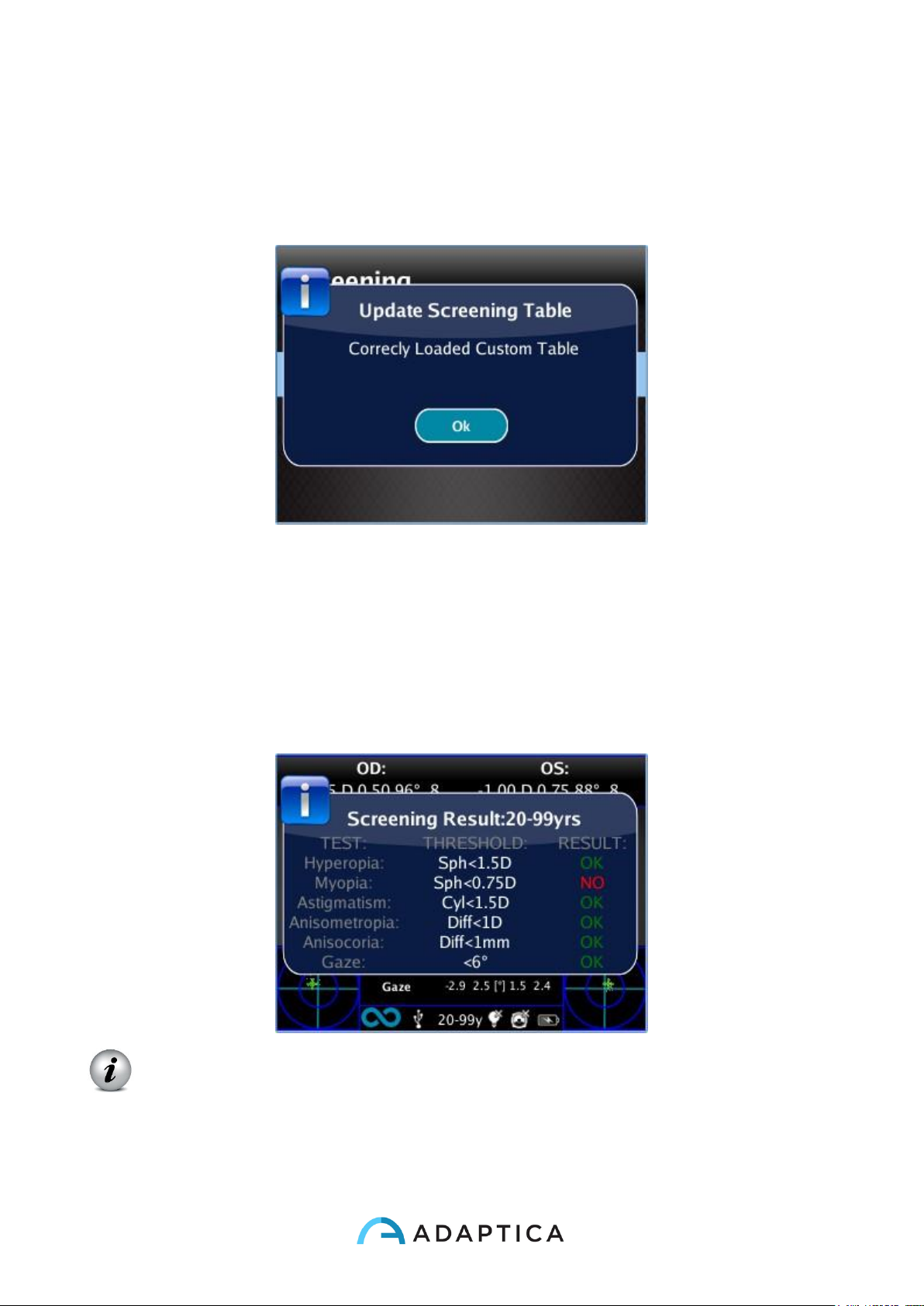
69
Upload
Uploading a table: from the menu Screening, select 'Update User Table', a message
indicates which table is uploaded (default or user) and if the table has been correctly
loaded.
Screening Measurement Result
To display the Screening Measurement result, from the home screen, press the right
button of the Cross button.
The following window is visualized:
NOTE: Screening Measurement Result is an Auxiliary window. Read the relative
paragraph for more information.
Pairing and transferring a 2WIN test to VisionFit
Page 70
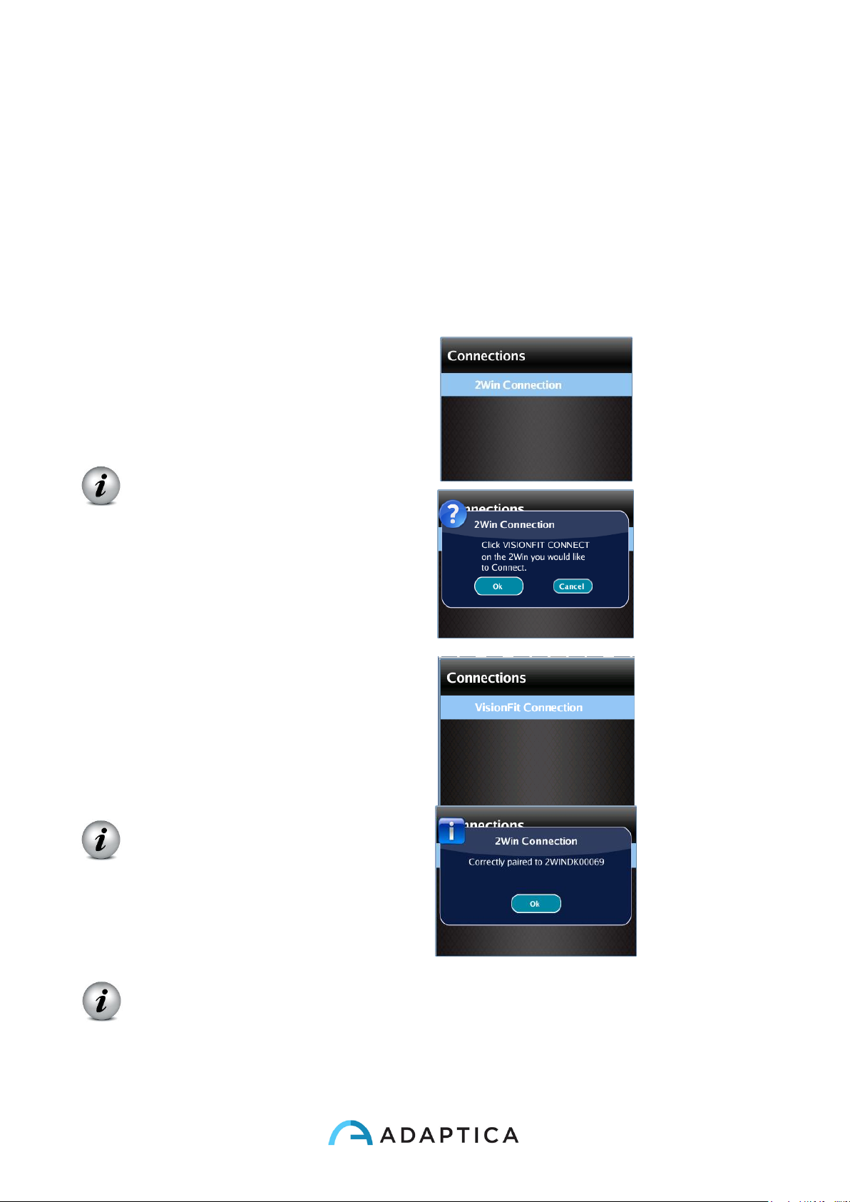
70
The second Adaptica’s product, VisionFit or VisionFit-SC, can be connected to the 2WIN.
Since VisionFit system is a mobile and wearable subjective refractor (phoropter), it’s pos-
sible to transmit 2WIN objective refraction results to the VisionFit in order to speed-up the
refraction process.
a) Pairing VisionFit and 2WIN
1. Activate WI-FI on VisionFit
2. Activate WI-FI on 2WIN and choose the same WI-FI Network as the
VisionFit
3. Select the 2WIN Connection from
Menu > Settings > Wireless >
Connections > 2WIN Connection
Do not close the window.
4. Select VisionFit Connection from
Menu > Settings > Wireless >
Connections > VisionFit
Connections
A new window notifying the
correct pairing will be
displayed
NOTE: pairing does not have a preferred sequence order (VisionFit - 2WIN).
Pairing can also be performed in reverse order (2WIN-VisionFit).
Page 71
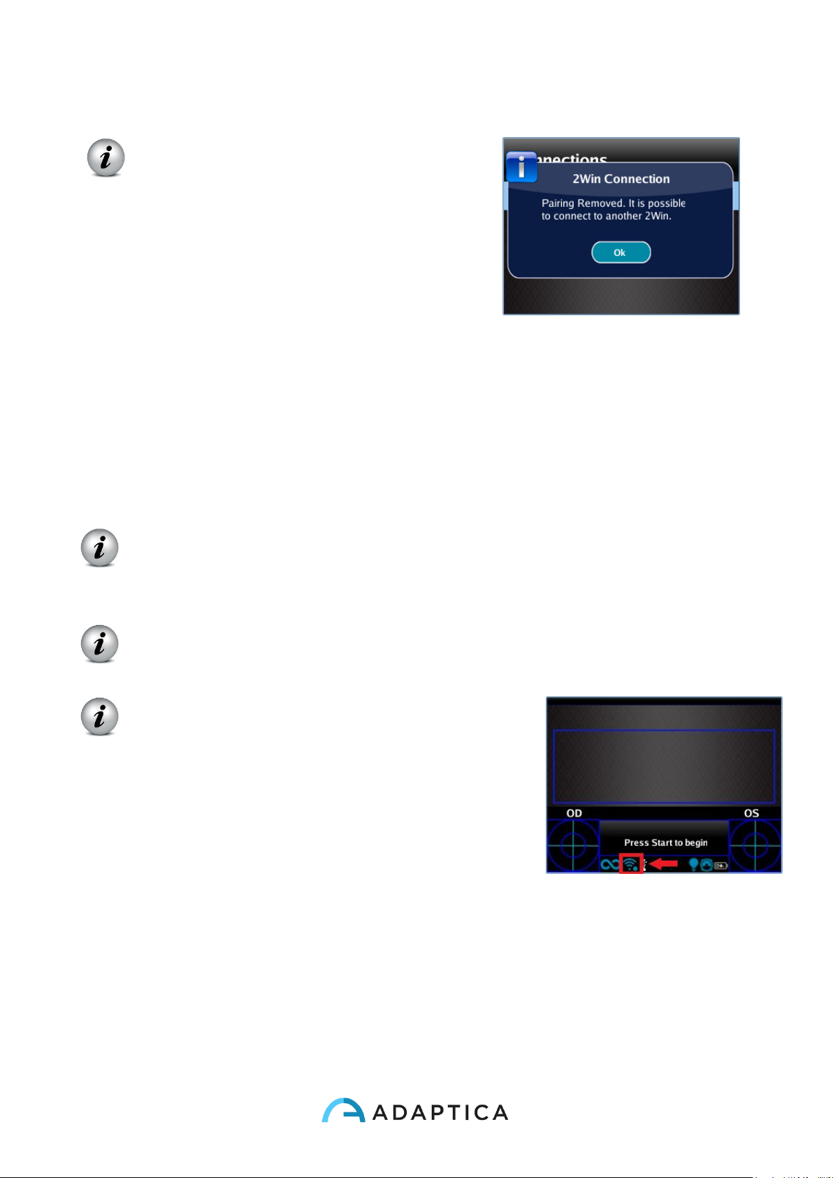
71
NOTE: remove the pairing (from VisionFit)
by selecting:Menu >Settings >Wireless>
Connections> 2WIN Connection.
b) Transferring a 2WIN test to VisionFit
To transfer a 2WIN measurement to VisionFit, follow the steps below:
5. Perform a test using the 2WIN. Press the joystick down in 2WIN. 2WIN data will
appear instantly on the right side in VisionFit (Reference data area). If the 2WIN test
has already been performed, browse the 2WIN “Browsing Mode” and hold the
joystick down. Data will appear in the Reference area in VisionFit data.
6. Press VisionFit joystick (menu button) to the left if you want to add data to the
Subjective Area.
Since two devices (2WIN and VisionFit) are paired, transfer will be performed
following steps 5 and 6. Pairing must be performed again only if you change
devices (2WIN or VisionFit) .
Not available measurement from 2WIN can’t be transferred on VisionFit.
Blue sphere near WiFi symbol indicates the
connection with the VisionFit.
Page 72

72
11. Wireless connections
WiFi connectivity
2WIN equipped with WiFi module (a label under the USB connection
door identifies the presence of module) can be connected to a WiFi
connection.
a) It is possible to download and visualize patient data from the 2WIN to an
external device (e.g. Tablet, smartphone).
This can be done with the use of any SFTP client - Secure File Transfer protocol.
b) You can also insert patient data details such as name, surname, date of birth
from an external keyboard.
This can be done with an application (VNC +SSH software) to be installed in a iOS and
Android smartphone/tablet device or in a personal computer with Windows or MAC OS.
This picture shows that before starting any networking operations the 2WIN must be connected to a wifi Local Area Network. The user
must insert the appropriate credentials in order to log the 2WIn to the Wifi access point present in the office/room. The access point will
assign a IP number to the 2WIN
Page 73
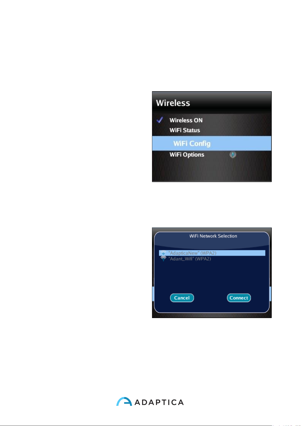
73
In order to enable the wireless (WiFi connectivity) in the 2WIN-W is necessary to follow the
following steps:
In order to enable the wireless (WiFi connectivity) in the 2WIN-W is necessary to follow the
following steps:
1. Click on “Wireless ON” from
Menu > Settings > Wireless >
Wireless ON
You will see the item Wifi
Activation and a tick will be
displayed next to the label
Wireless ON.
2. Select the item ”Wifi Config” and
push the cross button to find the
networks available.
3. Select your favourite Wifi
network, then push the cross
button to make appear the
network password insertion
window.
- Insert the Password of the
network;
- select and push the button
“Done”;
- select and push the button
“Connect”.
Page 74
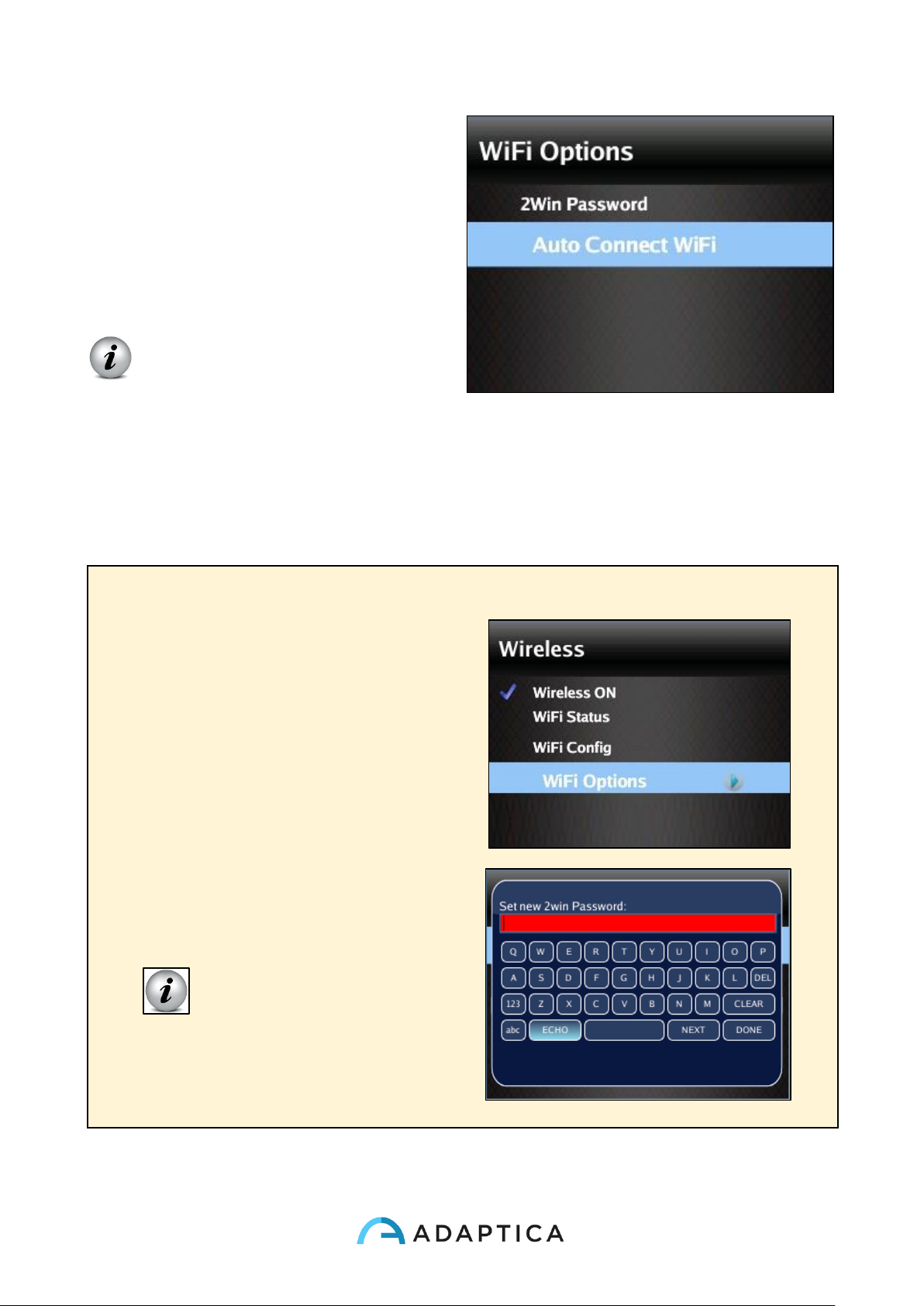
74
If you want, select Autoconnect
in “WiFi Options” (Menu >
Settings > Wireless > WiFi
Options).
In this way, if you lose
connection, 2WIN will reconnect
to the network automatically.
NOTE: if selected, wireless will
be activated automatically after
power-on.
4. Click on the item WiFi Status (or directly from Notification Center) to (1) check if
the 2WIN is connected to your network and to (2) determine the IP of 2WIN.
– WARNING –
The default password of 2WIN for
networking services (SFTP and
VNC + SSH) is adaptica.
The 2WIN password is a security
key for the system.
To change the password, go to
“WiFi Option” and set the new
security key.
NOTE: For security
reasons, It's
recommended to change the
password as the default one is
common to all 2WIN.
Page 75
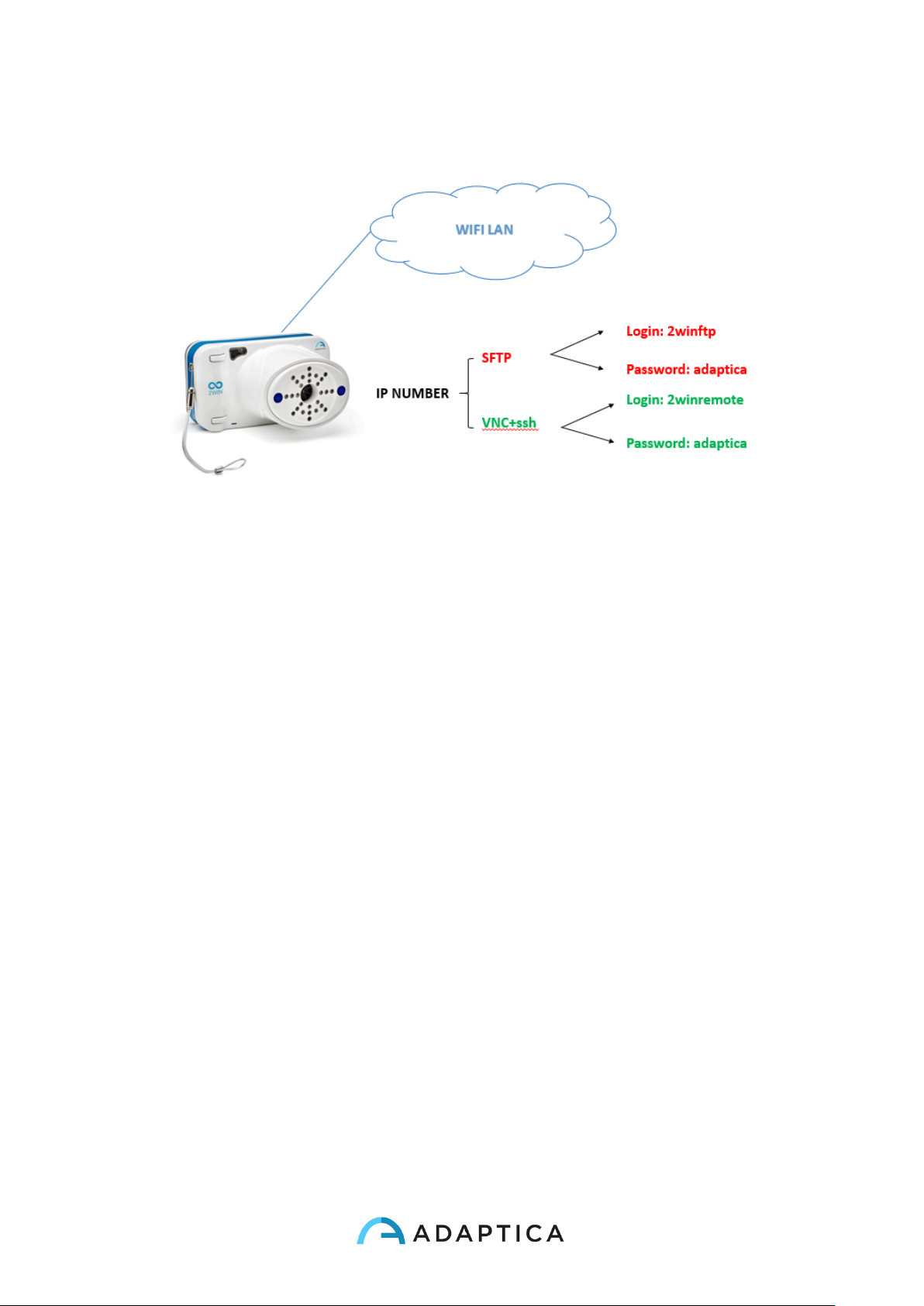
75
Sftp e vnc + ssh access credentials
The sftp access to 2WIN is carried out with the following setting:
User: 2winftp Password: adaptica*
There must be a Micro SD card to view the content.
Port: 22
*adaptica is the default password if not changed by user
--- --- --- --- --- --- --- ---
The VNC+SSH access to 2WIN is carried out with the following setting:
User: 2winremote Password: adaptica*
Port: 5900
*adaptica is the default password if not changed by user
Page 76
76
SFTP and VNC+SSH suggested softwares
MAC OS X
ANDROID
iOS
PC WINDOWS
(computer)
(tablet)
(iPhone – Ipad)
(computer)
SFTP
Filezilla
Turbo ftp
FTP Manager Free
Filezilla
VNC + SSH
TightVNC Java Viewer
BVnc
REMOTER Pro*
TightVNC Java
Viewer
*At the date of this manual review this application is not free
NOTE: Adaptica suggests the use of the above applications/software for
working with the SFTP and VNC + SSH services of the 2WIN.
The specific (1) installation procedure, (2) use and (3) support of these apps
can be acquired reading the specific apps user manuals. The 2WIN user
MUST read those manuals.
Keyboard command for the use of vnc+ssh
Once the VNC + SSH app is connected to the 2WIN, the procedure to input patient data
(after the measurement) is:
1. Type with your virtual keyboard the Enter button.
This will show in the smartphone/tablet and in the 2WIN the KEYBOARD
MODE.
2. In the virtual keyboard you can input data, switching between the data fields
using the “full stop” (.) button.
3. When the input of the data is finished press again the Enter button in your
virtual keyboard.
4. You can continue working on the 2WIN for saving or printing data.
Page 77
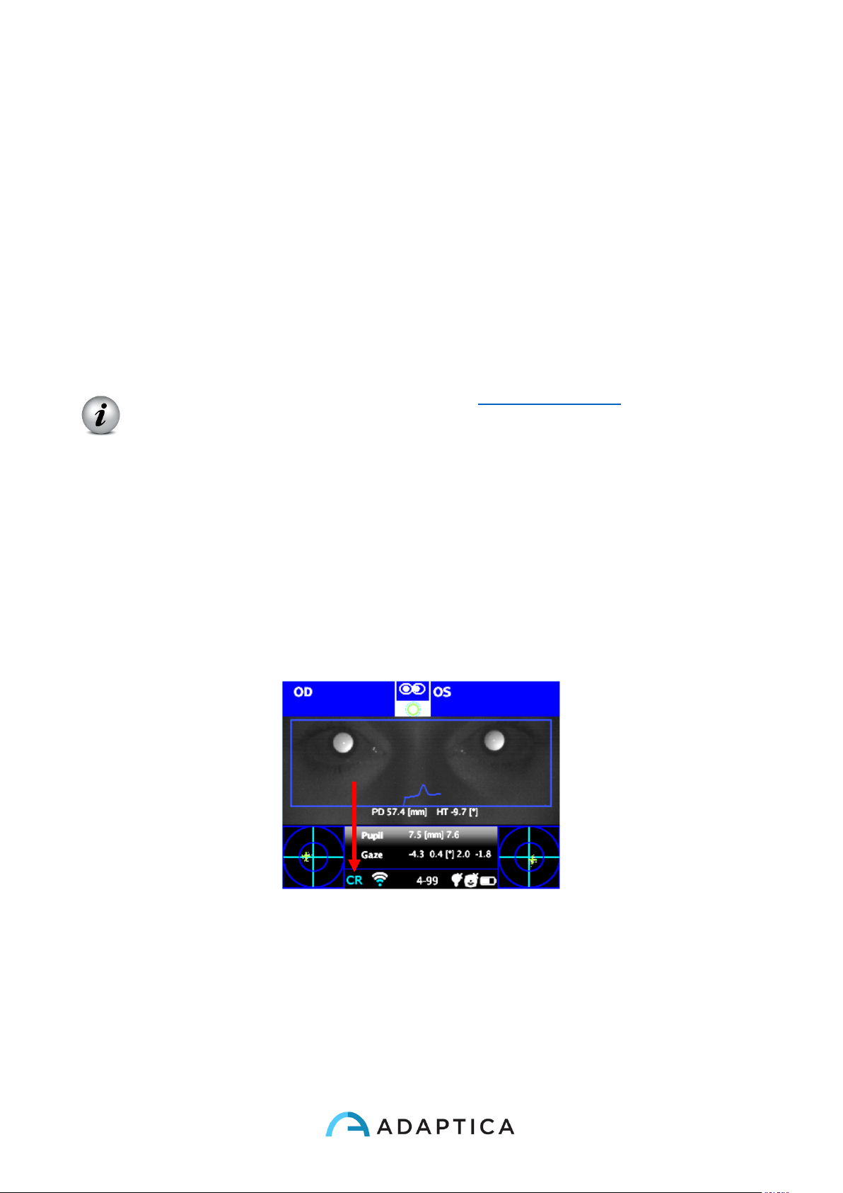
77
12. Applications (Packages)
It is possible to increase the 2WIN capabilities/functions with the installation of additional
software packages (from version 4.0 the new name of these packages is
“APPLICATIONS”);
Each application will be described at the end of this manual. You will be notified via email
about the availability of a new 2WIN software application. In this document it is described
the installation/management of additional applications.
Installation
Send an e-mail for a application request with the serial number of your 2WIN. The
complete list of 2WIN software applications at www.adaptica.com.
A file will be sent to you by mail; copy this file in the root of your SD card. After
copying, restart the 2WIN.
Activation
After the installation, the application will not enabled by default. To activate the application
earlier installed, navigate the menu to Menu>Functions>2WIN Applications and see all
installed applications.
Push right the CROSS button to go into the submenu and select the item that you want to
activate.
Push center the CROSS button to activate the application.
The icon of the main application active for the main visualization window is well visible in
the status bar.
Icon of the main application active
Page 78
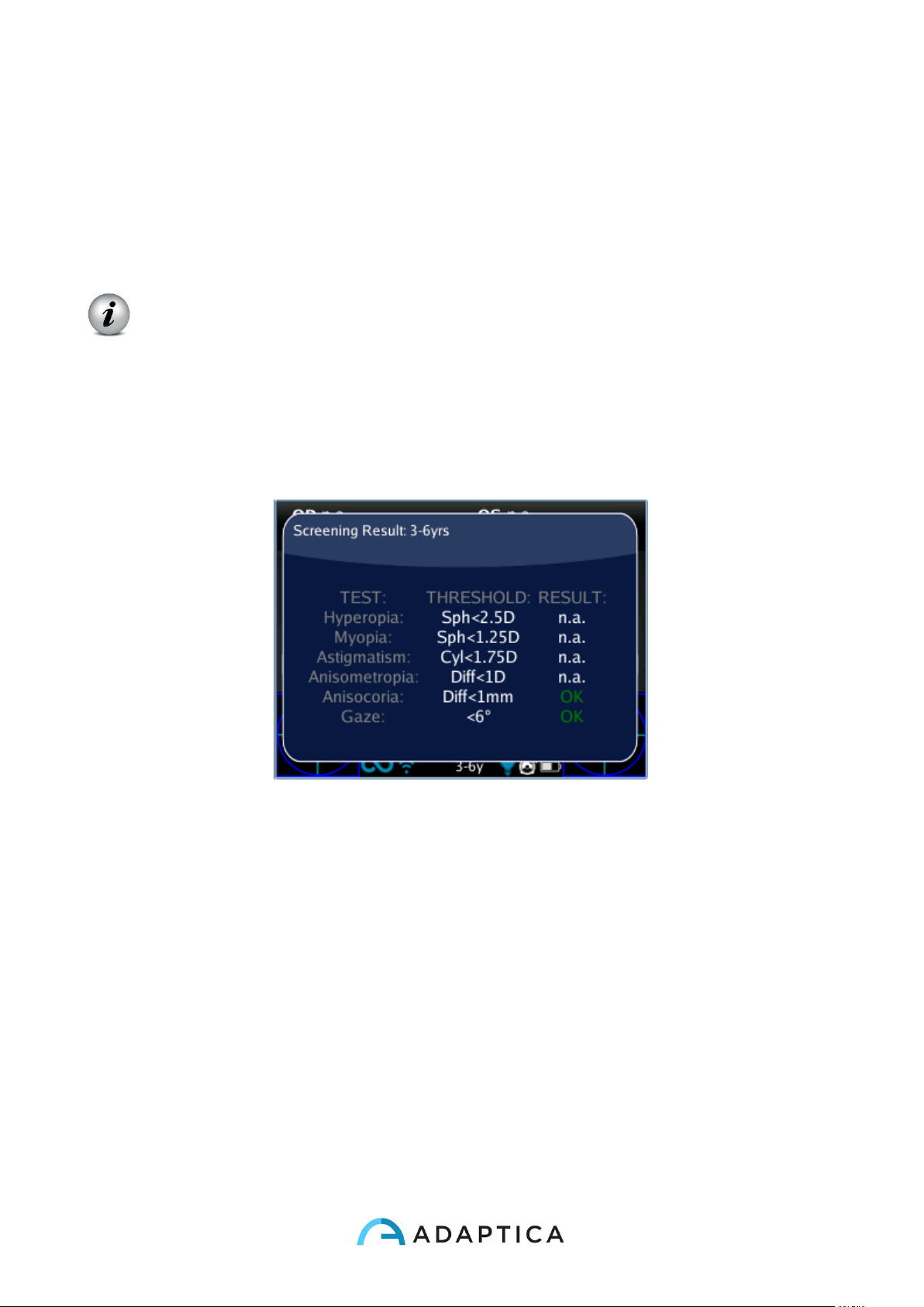
78
Visualization
The application display can impact on three types of display, (1) Wide Display (during
measurement), (2) Main visualization (measurement results), (3) Auxiliary (to display
something more than the result itself (eg screening in normal function.).
The main application is the displayed one that appears in the main visualization at the end
of the measurement.
When you don’t use the default application for refraction measurement, the
main measure window is blue coloured.
Auxiliary Windows
From Main Screen of 2WIN, push right the CROSS button to display the Auxiliary window
(default is screening result).
es. Screening Results
Press BUTTON B (print button) to display the Auxiliary Window choosing tab. With LEFT
and RIGHT button you can choose your preferred window. (Note: you can select the
default Auxiliary Windows to be showed by pressing up the CROSS button. The
application will be highlighted, so that by pushing LEFT or RIGHT you can move it in the
preferred position. The Application on the left is the default Auxiliary window showed.
Press up again to exit the moving option).
Modes (2WIN Applications)
If you click the BUTTON A (On/Off) Modes screen will be shown to display (from version
4.0 this window is called 2WIN Applications)
Page 79
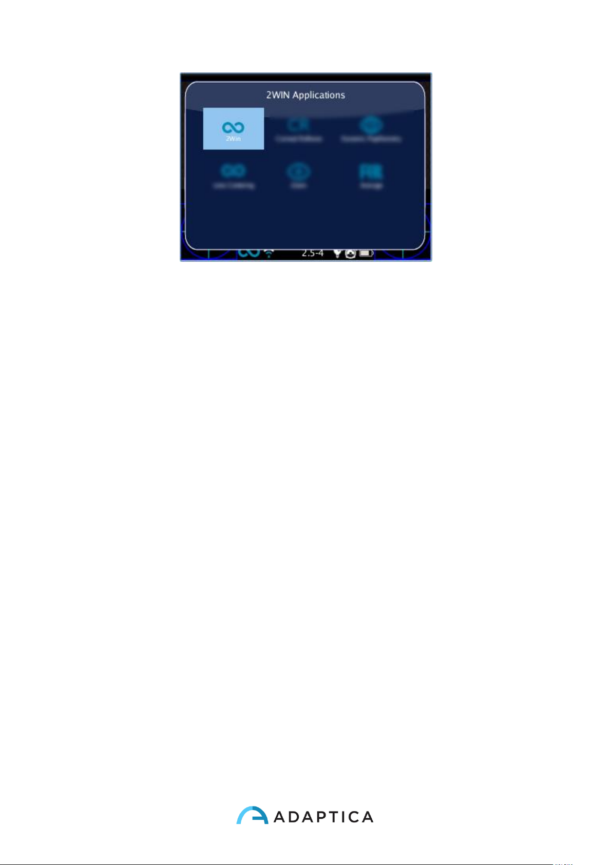
79
It is possible to navigate and to see all installed applications into the device. By clicking
with the cross BUTTON on the application icon, this application will be the principal one in
Main Display and it will be set first in Auxiliary Windows automatically.
Interaction
To change application settings navigate the menu to Menu>Functions>2WIN Applications
and select the item that you want to set into the submenu related to your application.
2WIN Applications notification
When a application generate a notification, the notification center shows a P like icon to
show that the notification comes from applications.
Print
Each application gives you the ability to print data in a combination of 3 modes: irda print,
pdf Strip, pdf.
13. Software upgrade instructions
In case of future software releases to upgrade the 2WIN, the user will be contacted by
means of an information note (email/fax/phone call) containing the description step by step
of the instructions to upgrade the device.
ATTENTION: the operator is not allowed to perform a DOWNGRADE of the 2WIN
software. Adaptica is not responsible for the improper use of the device with a downgraded
software version.
ATTENTION: when the software update procedure will be performed, the 2WIN battery
must be fully charged.
Page 80
80
14. Maintenance and cleaning instructions
No maintenance operations are required by the system.
If the measurement never ends correctly and the hardware test does not reveal any
hardware problem, the system may be periodically verified, by means of a procedure
called “white fielding”. For such verification follow these instruction:
1. take a commonly used A4/letter/legal printer/copy machine white sheet of paper
and place it at 1 m distance from the instrument;
2. turn on the system, enter the menu and then the Functions/Aux sub-menu;
3. select White Fielding option;
4. start an acquisition while pointing the system to the white sheet of paper;
5. a message will appear showing the test result;
If necessary, it is possible to clean the device with a lightly moist microfiber cloth in the
external chassis. In order to clean the frontal camera lens use any cotton-tipped swab and,
if necessary, use also some dust-aid cleaner liquid with no-alcohol.
Do not use sprays or alcohol to clean the system.
Storage instructions
The device needs to be stored under the following environmental conditions:
Temperature: -10 – 60 C° (14 – 140 F°)
Humidity (max): 90% not condensing
Instructions for correct disposal of the device
The device is made of different materials, such as plastics, aluminium, electronic parts: in
case of instrument disposal, please separate the various materials and follow the laws and
regulations regarding disposal or recycling for each material effective in your own country.
Separate collection for electrical and electronic equipment
The European Directive 2002/96/EC establishes the separate collection for Waste of
Electrical and Electronic Equipment (WEEE). The users of Electric and Electronic
Equipment (EEE) have not to dispose of WEEE as unsorted municipal waste, they have to
Page 81
81
collect such WEEE separately. The available return and collection system is defined by the
local public administration, or in alternative an authorized company can recycle the WEEE.
Please refer to public administration about the separate collection, if this information is not
available, contact the manufacturer of the equipment.
Users have a fundamental role in contributing to reuse, recycling and recovery of WEEE.
The potentially dangerous substances contained in the WEEE can pollute the environment
and produce harmful effects to the human health.
Below, there are a few indications of specific dangers of some substances, which may
leach in the environment and in the water system.
• Lead: damages the nervous system of humans, it affects the endocrine system, the
cardiovascular system and kidneys. It accumulates and is very toxic for animals,
plants and micro-organisms.
• Cadmium: accumulates with a half-life of 30 years and can damage the kidneys and
cause cancer.
• Mercury: it is easily accumulated in organisms and concentrates through the food
chain. It has chronic effects and can cause brain damage.
• Chromium (Hexavalent): easily absorbed into cells with toxic effects. The results
can be allergic reactions, asthma and it is considered to be genotoxic (damages the
DNA). Especially dangerous when incinerated.
• Brominated Flame Retardants: widely used to reduce flammability (e.g. cables,
connectors and plastic cases).
Page 82
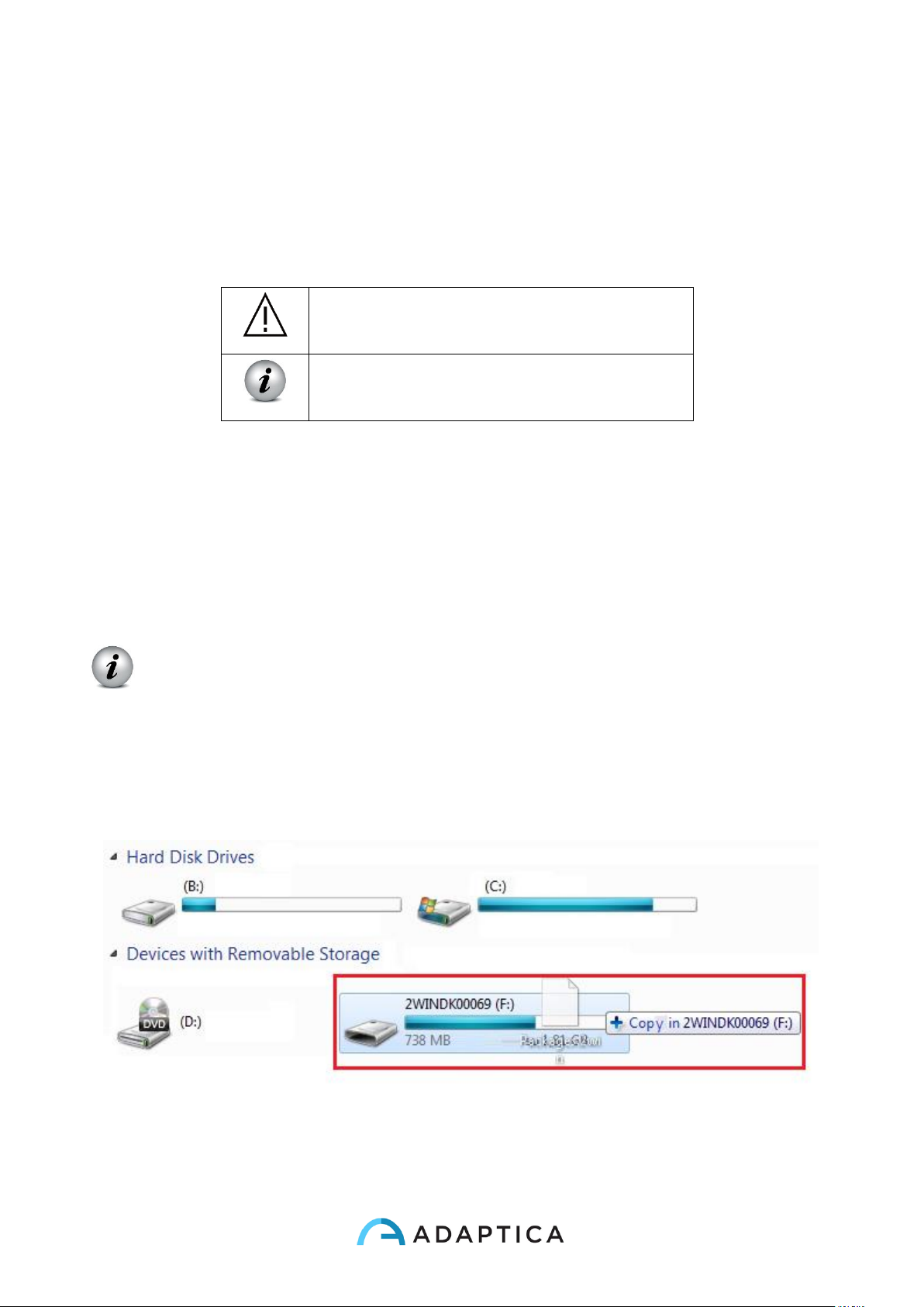
82
15. 2WIN Applications specific manuals
Legends of symbol
Warning: necessary information for safety
Important information
2WIN Applications installation (the same steps for every app)
1) Connect the 2WIN, with MicroSD plugged in, to your computer with the USB cable;
NOTE: if 2WIN is turned off, wait till it turns ON automatically once connected
to USB cable.
2) A new device will appear on the computer where you attached the 2WIN.
- Drag and drop the file “2WIN Applications.2wp” on the new device icon or with the
file Explorer of your computer copy the file “2WIN Applications.2wp” and past it in
the Root directory of the new device.
- safely remove the device from your pc;
- unplug the USB cable from the 2WIN and from the PC;
- turn the 2WIN off;
Page 83
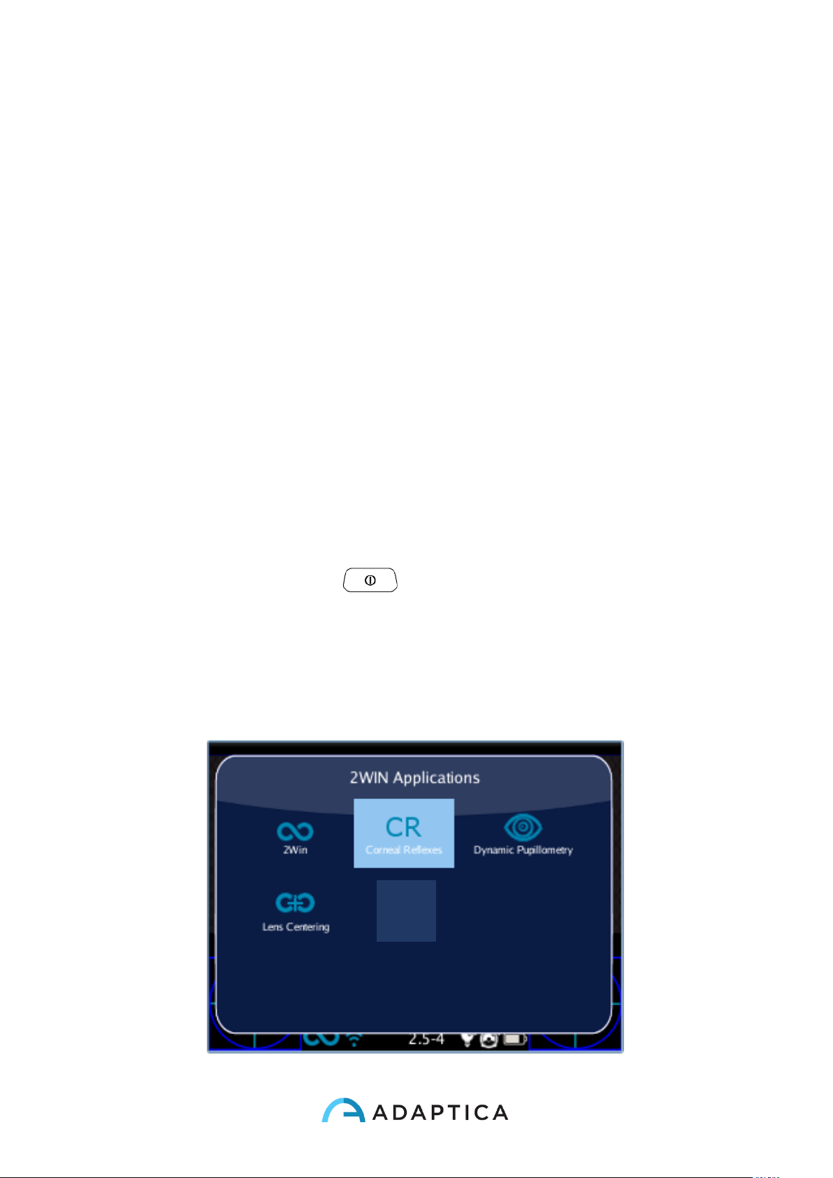
83
3) turn the 2WIN on;
4) the 2WIN Application is now available for activation;
Analysis of Corneal Reflexes Position (CR-App)
This function can provide information regarding the corneal reflexes position.
The App will add the feature to collect data from 3 measurements and analyze the corneal
reflex.
Results are expressed either in prism diopters or in degrees.
Corneal Reflexes App activation
After the installation this App must be activated to be utilized.
Activation: click the BUTTON A ( ) 2WIN Applications screen will be shown to
display.
Doing this, it is possible to navigate and to see all installed applications into the device.
By clicking with the cross BUTTON on the corneal reflexes application icon, this
application will be the principal one in Main Display and it will be set first in Auxiliary
Windows automatically.
Page 84
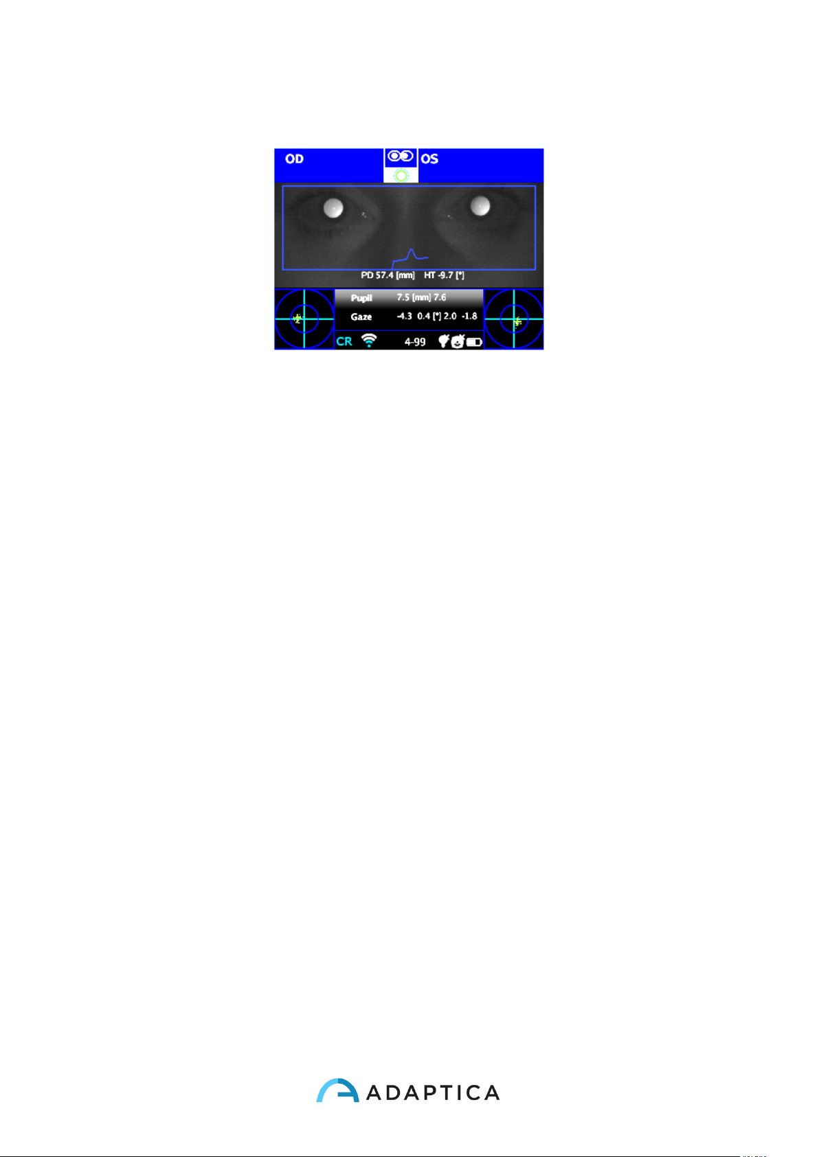
84
Modes screen
Main Visualization - Corneal Reflexes
Page 85
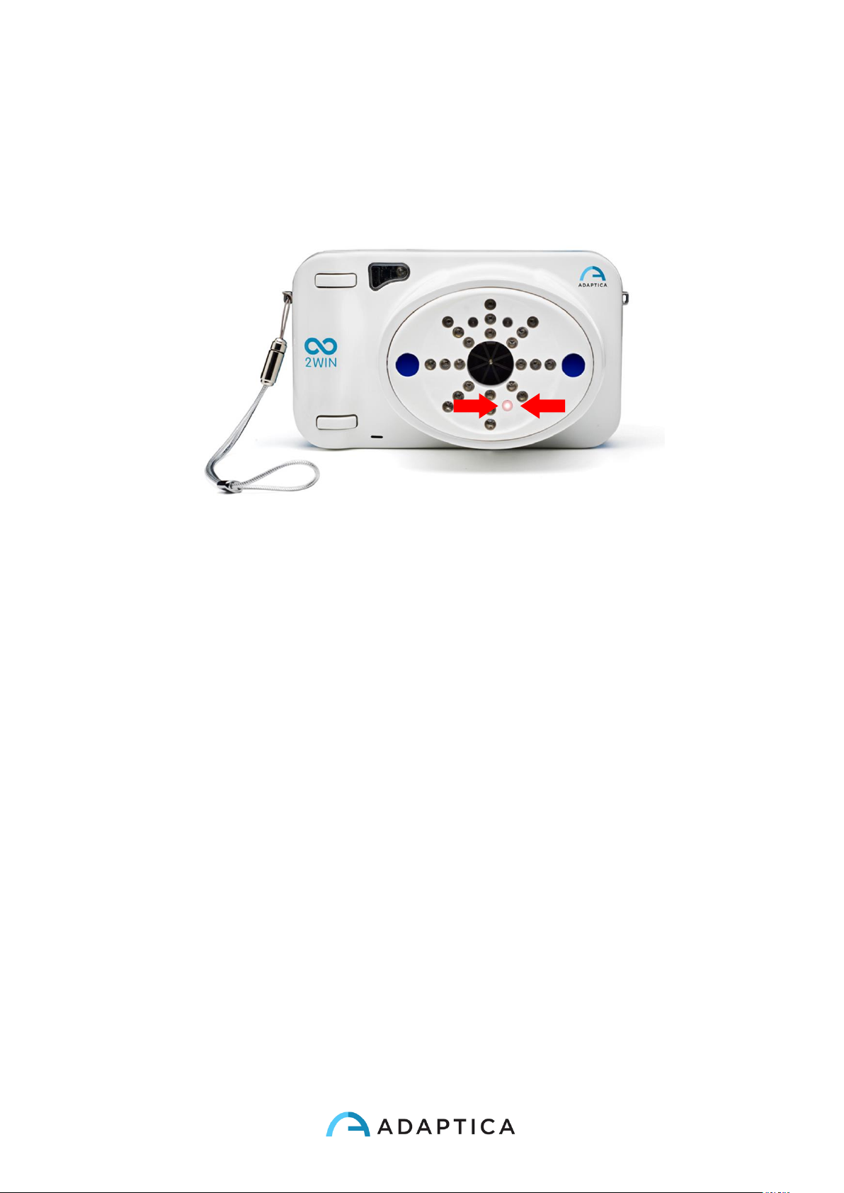
85
Corneal Reflexes exam
Tips for patient
Patient must gaze the White led that turns on during measurement with ‘Corneal Reflexes’.
White led
Exam
The procedure is the same as refraction measurements (the single binocular and
monocular acquisitions are much faster as the application is dedicated to eye alignment
and not to refraction measurement)
Use the top bar that gives feedback on the conditions for measurement: in particular, this
bar becomes red or green. When the bar is red, there are no conditions to acquire the
images correctly, on the contrary, when the bar is green, correct conditions for measuring
are satisfied and images can be acquired and processed correctly.
Measurement tips: usually the RED condition depends on a bad distance between the
2WIN and the patient. When the top bar is RED adjust the distance between the 2WIN and
the patient in order to focus the image and to obtain a GREEN top bar.
The steps to perform a measurement are summarized in the following list:
1. Once the conditions for the measurement are met, hold the device in your hands
and point it towards the patient.
2. Press and hold BUTTON S1 or S2, in order to start the measurement.
Page 86
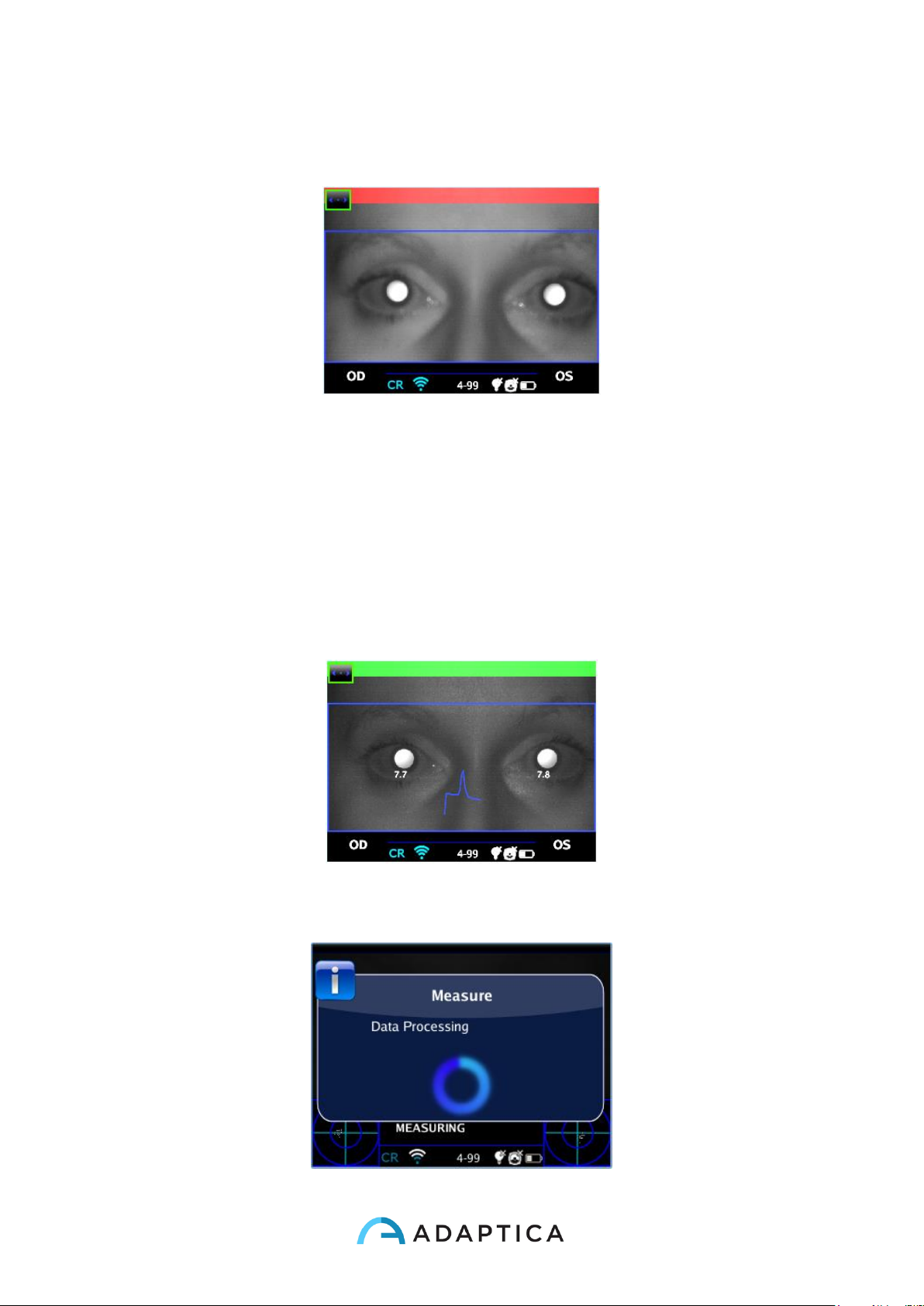
86
3. Center the eye/s of the patient in the display live area, inside the blue rectangle
(measurement area) – the message “FOCUSING” will appear.
Examination screen – bad focus
4. Adjust the distance to focus the image until the top bar is green (for details on
screen tips also see: Verify the position of the subject in 2WIN Operator Manual).
5. When the top bar is STEADILY green release the BUTTON S1/S2 – the message
"MEASURING" " will appear. PLEASE hold the 2WIN position until the message
DATA PROCESSING appears on the display.
Examination screen, top bar green - focus OK
Page 87
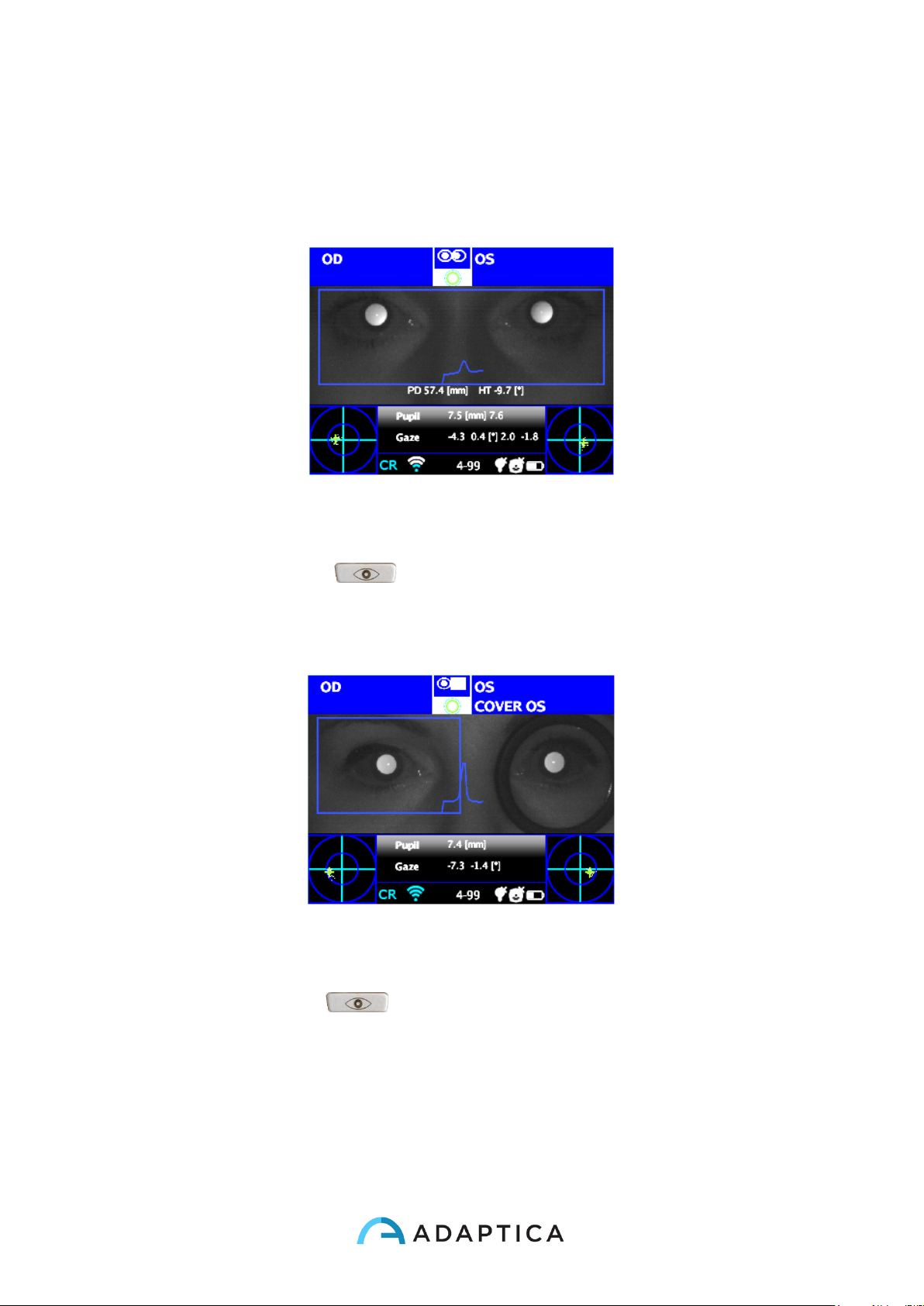
87
Data Processing
6. After the measurement a green indicator on the top bar of the display, at the center,
will give you the feedback of correct measurement:
Green Indicator
7. Click the BUTTON C ( ) and select the eye where you want to perform the
cover test, using the Binocular Occluder provided by Adaptica (NOT OTHER
OCCLUDERS) to cover the contralateral eye.
Cover OD
8. Repeat the steps 1 to 6 to get the measurement.
9. Click the BUTTON C ( ) and repeat the procedure on the other eye, moving
the eye occluder onto the contralateral eye.
Page 88
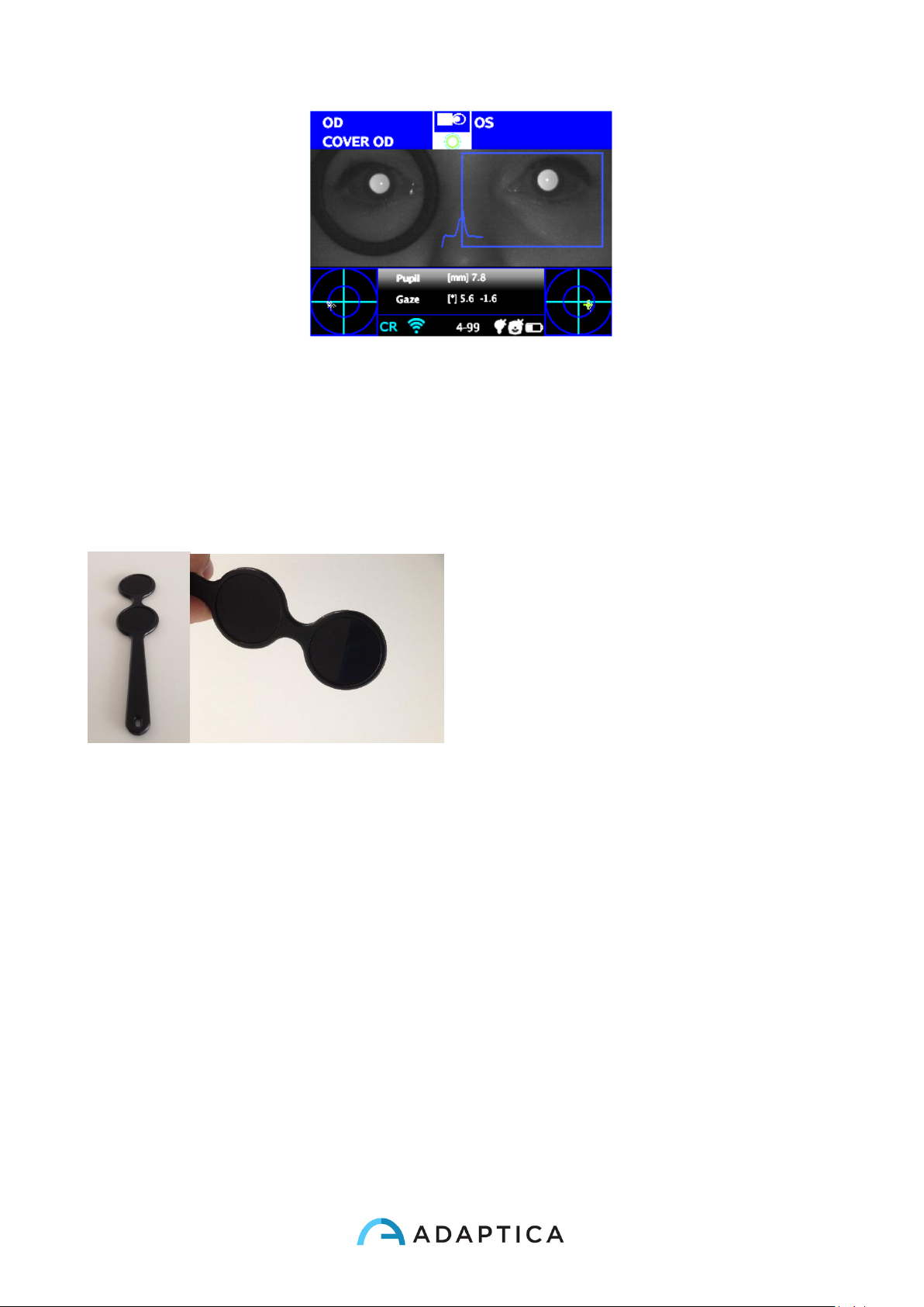
88
Cover OS
10. Repeat the steps 1 to 6 to get the measurement.
Adaptica’s Binocular Occluder. If no
information about phorias is required, a
traditional eye occluder can be
alternatively used.
Adaptica’s Binocular Occluder
Exam Results from ‘Corneal Reflexes’ App
Once completed the test, auxiliary window for the corneal reflexes analysis is
opened automatically (Menu > Functions > 2WIN Applications > Corneal Reflexes >
Options > Show at End).
This is an example of exam results of Reflex Symmetry application.
Page 89
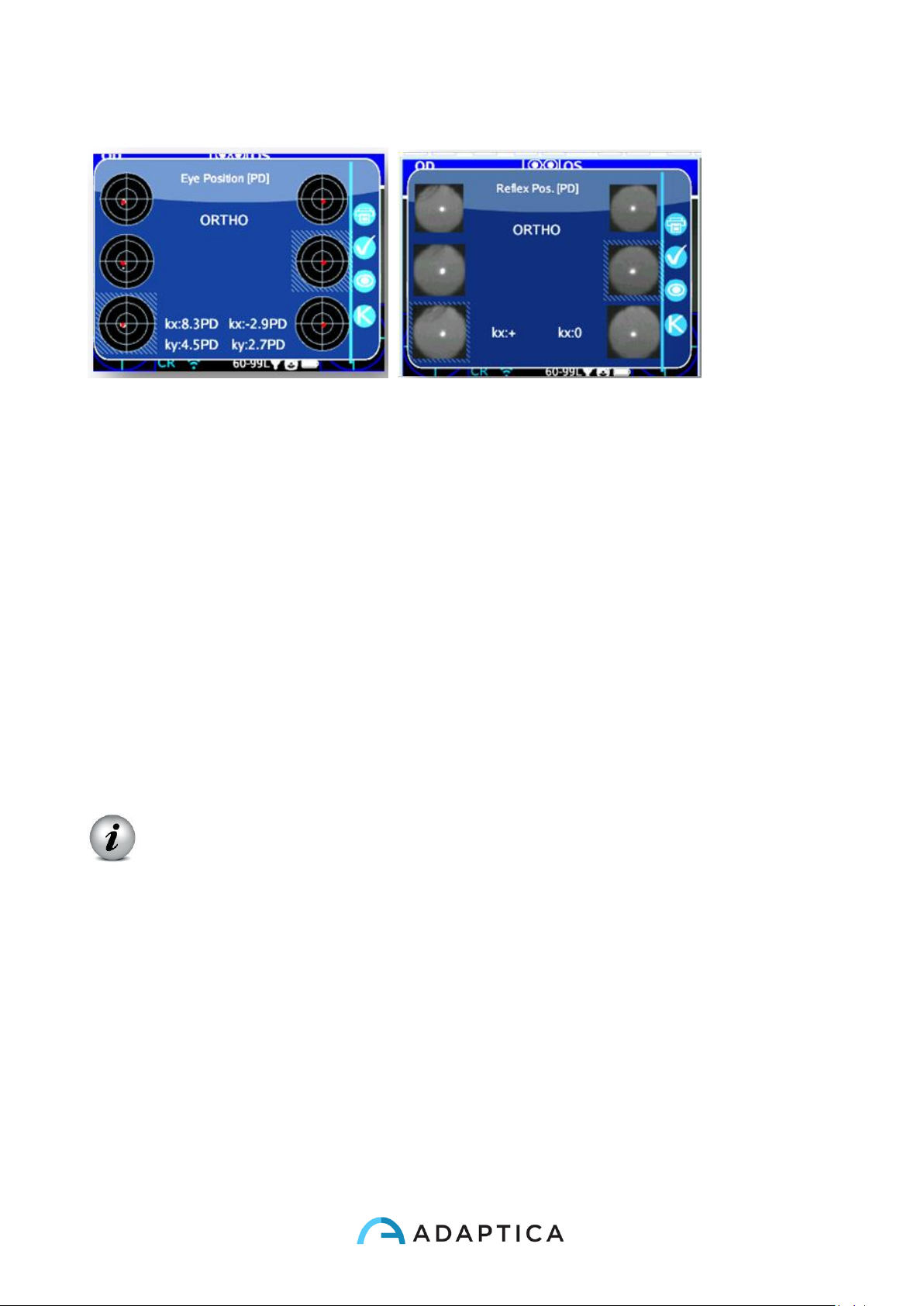
89
There are 2 columns with 3 circles, on the left and right side, related to the left and the
right eye information.
The circles on the columns display the position of the corneal reflex with respect to the
pupillary geometrical centre. The size of the circle is proportional to the pupil size.
The images represent from top to bottom:
- both eyes open
- right eye open, left eye cover
- right eye cover, left eye open
The covered eye is highlighted by a light blue square.
The cloud of points in each image graphically reports each individual corneal reflex
collected during the exam.
The red marker point in the mean of each distribution is the baricentral position of the
corneal reflexes.
Note that the operator can switch between this description (baricentral fixation) to the
simple pictures of the pupils just pressing the EYE button on the 2WIN.
When the position of the corneal reflexes comparing the binocular test with the monocular
infrared cover test of each eye is not significantly changing, that is when the baricenter
Page 90
90
changes its position less than the threshold value (mm) selected in the settings (Menu >
Functions > 2WIN Applications > Corneal Reflexes > Options > Threshold), the output is
"ORTHO".
When a manifest asymmetry of the corneal reflexes is detected without cover test the
output is ET: esotropia; XT: exotropia.
When an asymmetry of the corneal reflexes appears only under “infrared” cover test the
output is EP: esophoria; XP: exophoria.
When a vertical deviation appears the output follows the same rules above exposed (HT:
hypertropia; IT: ipotropia; HP: hyperphoria; IP: ipophoria.
WARNING: the messages ET, XT, EP, XP, HT, IT, HP and IP SHALL NOT be
misunderstood as a diagnosis or an hint for diagnosis. For instance, a loss
of fixation by the patient during the exam could cause an asymmetry not
related to any pathology. The measurement shall in any case be used to
refer the patient to an eye care pratictioner for an evaluation.
The angle of deviation can be expressed either in prism diopter (PD) or in degrees (°): to
change Notation Menu > Functions > 2WIN Applications > Corneal Reflexes >
Options > Notation)
Please note that cover test can be done both with an infrared occluder or
with a conventional occluder. However phorias can be detected and
measured only with the infrared occluder.
K angles values are displayed on the bottom of the auxiliary window.
The default output shows the following:
- Horizontal k angle (labelled as 'kx'): the output is '+' when the corneal reflex lays
nasal to the centre of the pupil, '0' when the corneal reflex coincides with the
geometrical centre of the pupil, '-' when the corneal reflex is on the temporal side.
- Vertical k angle (labelled as 'ky'): the output is 'S/D' when the corneal reflex of the
left eye lays superior to the corneal reflex of the right eye , 'D/S' in the opposite
Page 91
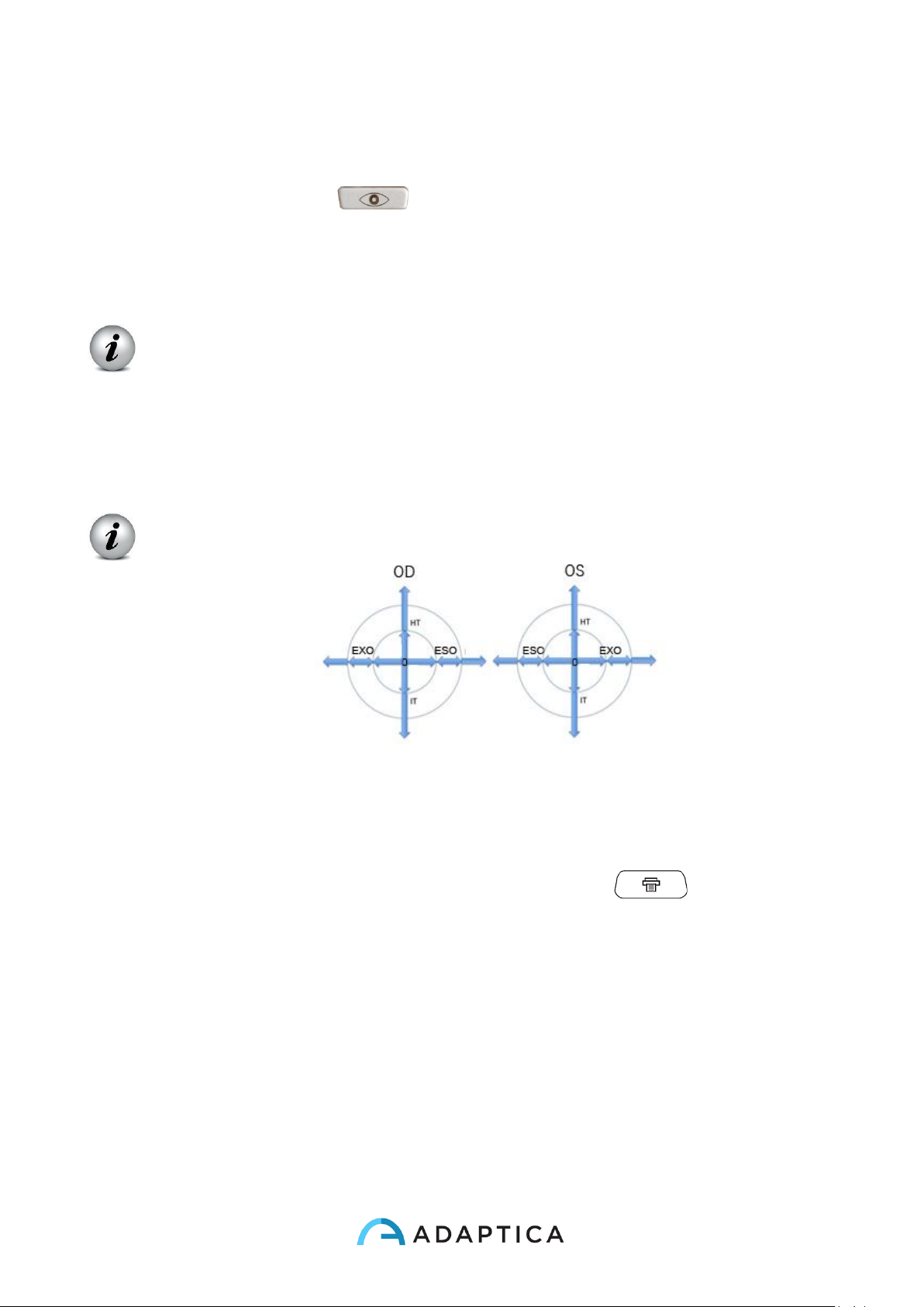
91
case. When there is a vertical disparity inferior or equal to the established threshold,
no vertical disparity message is given.
By clicking on the C button ( ), it is also possible to toggle between this and a
second layout, where k-angle is expressed in terms of its horizontal e vertical coordinates.
Threshold levels can be changed, by default they are factory set to 5DP for
the kx output and to 4DP for the ky output.
Menu > Functions > 2WIN Applications > Corneal Reflexes > Options >
Threshold
The following picture gives a graphical representation of the codes.
Print
Results can be saved on SD memory by clicking the B button ( ) directly from the
Auxiliary windows displayed.
Page 92
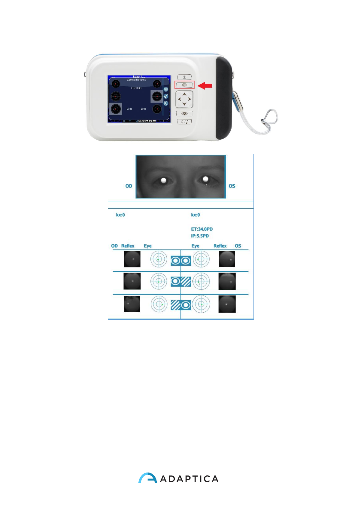
92
An example of Corneal Exam Report (PDF)
In the printout the results are displayed in degrees or prism diopters, the concentric circles
representing 10 units steps of that unit (10, 20, 30 Prism diopters or degrees). The pupil is
sized accordingly and cropped if bigger that 7 mm. In the report is also possible to see all
the pupil pictures.
Page 93
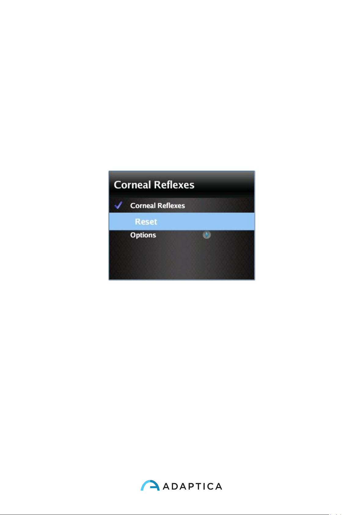
93
Measurement reset
If you want to perform a new examination or to avoid results just made, measurement may
be reset in three ways:
• By saving data on SD memory
• By choosing a new application
• By clicking Reset from Menu > Functions > 2WIN Applications > Corneal Reflexes >
Reset
Reset in Corneal Reflexes
New measurement overwrites old data with new data automatically.
Page 94
94
Dynamic pupillometry application
This function can provide information regarding the pupils response (diameter
during time) when the eyes of the patient are illuminated with a known visible and
programmable white light created by the 2WIN.
The visible stimulus light can be programmed by the operator in intensity and duration.
Results are expressed in a graphical image showing the pupil response to the visible
stimulus and through some numbers showing the estimation of pupil response time,
reaction time and slopes of the change in diameters versus time.
Page 95
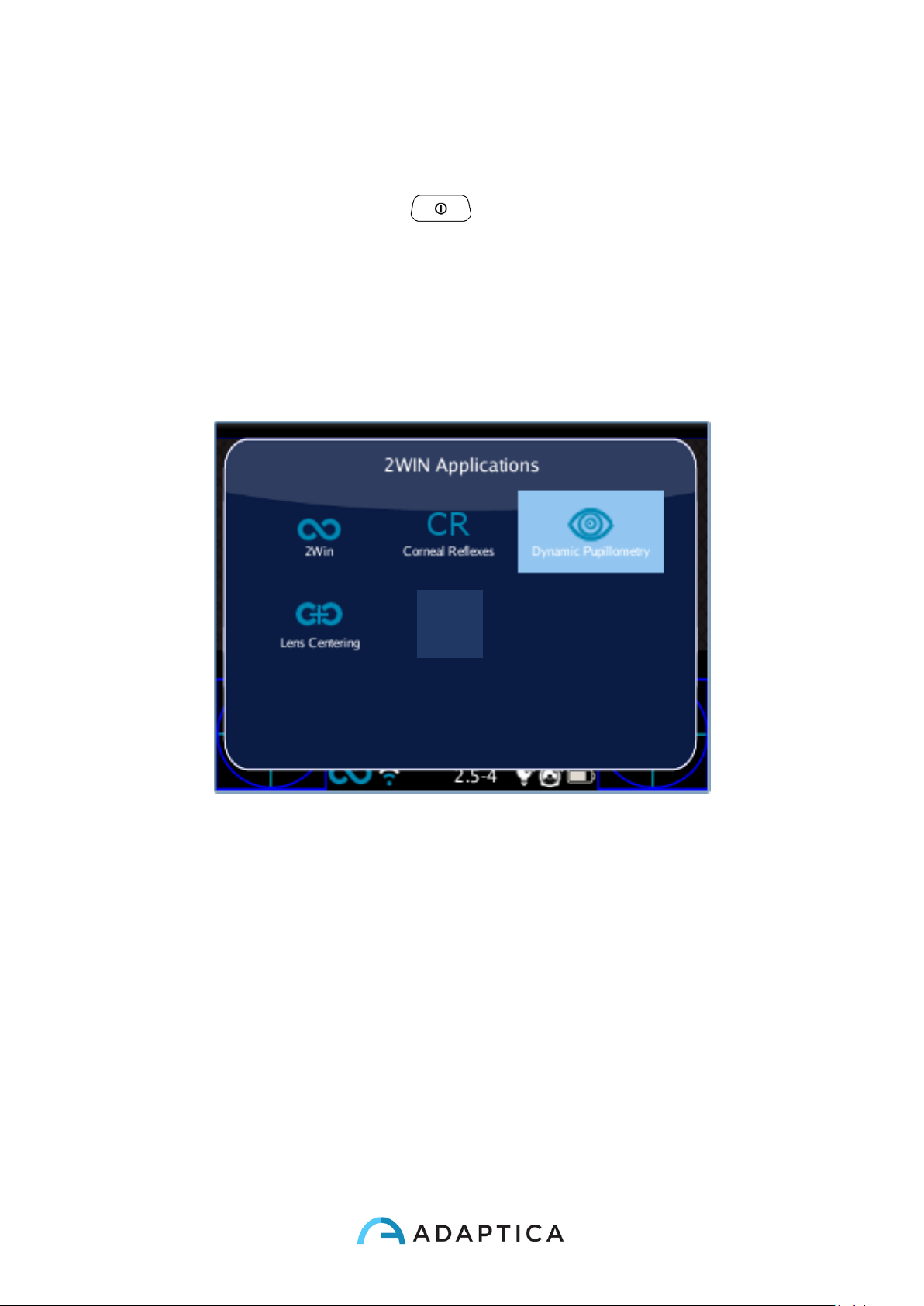
95
Dynamic pupillometry application activation
After the installation this application must be activated to be utilized.
Activation: click the 2WIN BUTTON A ( ) 2WIN Applications screen will be shown to
display.
Doing this, it is possible to navigate and to see all the installed applications into the device.
By clicking with the cross BUTTON on the Dynamic Pupillometry application icon, this
application will be the principal one in Main Display and it will be set first in Auxiliary
Windows automatically.
Page 96
96
Dynamic Pupillometry exam and modes
There are three operative modes for this application:
1) Default mode: This mode makes a first calibration of the eye response values taking
into account also the ambient illumination
2) Manual mode: the operator can configure manually the set of visible light stimuli.
The duration of each stimulus lasts minimum 2 seconds. For configuring this mode,
the operator has to write a TEXT file in a normal text editor in a computer ad save
that file in the SD memory of the 2WIN.
3) Calibration mode: like the Manual mode, this exam mode needs a configuration file
written in the SD card of 2WIN. At the beginning of the exam this mode illuminates
the patient with 4 calibration impulses in order to understand automatically the good
final exam impulse. This final light signal will be used in the last part of the
measurement. 2WIN takes into account also the ambient light, on this base 2WIN
decided to use the 50% of the intensity or not in the first calibration pulses and in
the final one.
The overall measurement lasts 14 seconds in all the modes
Page 97
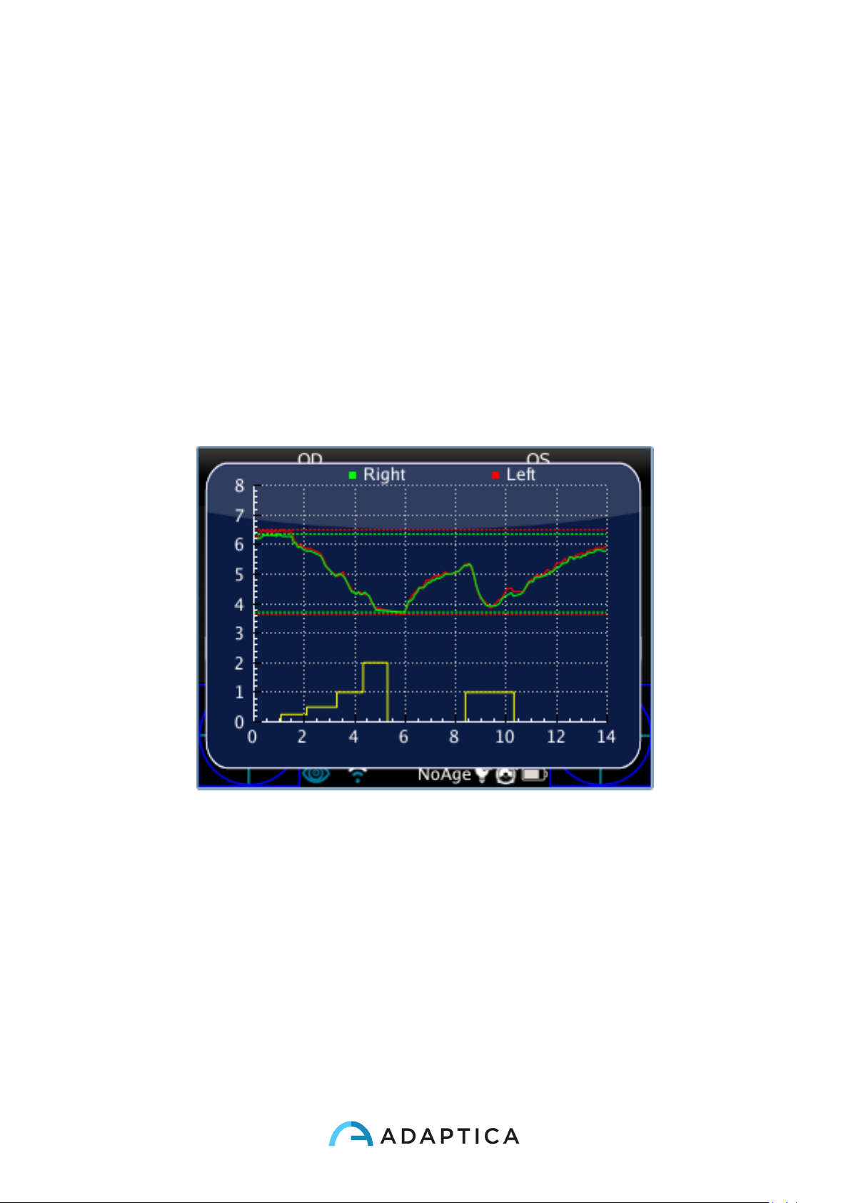
97
Exam
The procedure to take the exam is the same as the normal 2WIN refraction
measurements. There’s a slight difference related only on the 2WIN graphical
interface.
FOCUSING PHASE: start the focusing aiming at the two eyes of the patient keeping
pressed the S1/S2 button of the 2WIN. Move the 2WIN toward or backward and try to
maximize the length of the color moving bar on the bottom of the user interface. When you
reach the maximum, please release the S1/S2 button in order to start the measurement
phase;
MEASUREMENT PHASE: stay in the position
When you released the S1/S2 button till the exam automatically finish (after 14 seconds).
Standard mode
The standard mode is activated in the Dynamic Pupillometry applications only if it’s not
present in the 2WIN SD card the right configuration file or if this file is not edited in the
proper way. The standard mode creates (after a dark second) a sequence of 4 bright light
impulses. During these pulses 2WIN detect the pupillary reaction. If the pupil diameter,
during any of the 4 pulses, decreases below the 10% of the initial state (when the
measurement begins) or it reaches a dimension less than 3.5mm then the initial calibration
Page 98
98
of this mode stops and then a final bright pulse will be turned on (in this case this pulse will
have double intensity compared to the last that caused the stop of the calibration).
Moreover, if the ambient light is too low all the pulses (calibration and final one) will be
reduce by half (in this case in the display of 2WIN the maximum value will be 1 and NOT 2
Manual mode
In order to activate this mode the operator has to write with a text editor a file (named
pupilresponse.txt) and copy it in the SD memory of the 2WIN.
The file must contain 7 rows, each row represents a 2 seconds phase of the
measurement. The numerical value to be written in the raw represents the intensity of light
in a scale spanning from 0 to 100.
Example configuration file
0
8
0
16
0
32
0
This file creates the following sequences of exam phases:
• Phase1 = dark condition (no visible illumination), 2 seconds
• Phase2 = 8% of the maximum visible light is turned on, 2 seconds
• Phase3 = dark condition, 2 seconds
• Phase4 = 16% of the maximum visible light is turned on, 2 seconds
• Phase5 = dark condition, 2 seconds
• Phase6 = 32% of the maximum visible light is turned on, 2 seconds
• Phase7 = dark condition, 2 seconds
Page 99
99
NOTE that any value greater than 100 value will be considered 100%, while 0 stands for
dark condition. The configuration file will not be considered if there will be a different
number of raws or different kind of characters, 2WIN will use the standard measurement
mode in this case.
Calibration mode
In this mode is again necessary to edit a file “pupilresponse.txt” and write it in the SD card
of the 2WIN.
The operator must decide 2 parameters and then 4 intensities of light for the calibration of
the system in this specific mode.
The two parameters are:
• T = is the minimum pupil diameter limit threshold. If during the 4 calibrating
intensities of light the pupil diameter of any patient pupil goes under this value, then
during the last and final measurement phase the 2WIN will use the corresponding
light intensity that caused that specific threshold crossing.
• M = multiplication factor of the calibration impulse
• P = is the desired percentage of pupil diameter variation
The four calibration intensities are written in the configuration file with A,B,C,D letters.
A,B,C,D values must be placed in ascending order.
The 2WIN during this calibration mode will start the exam with a starting 1 second of dark
condition, then it will switch between the 4 A,B,C,D calibration intensities, each of them
turned on for 1 second).
If the pupil diameter percentage variation is greater than the P parameter or if the
minimum pupil diameter is lower than T parameter then 2WIN will store the intensity value
(one of the A,B,C,D) that caused on of the above conditional pupil reaction (T or P
parameter). This value will be used to illuminate the patient in the final phase of the
measurement.
Example (pupilresponse.txt) file in the SD 2WIN card:
T4.2
Page 100
100
P15
M1.5
A8
B16
C32
D64
In this example the 4 light intensities at the beginning of the measurement will be 8%,
16%, 32% and finally 64% of the maximum light intensity. At the end of the measurement it
will be used a final light impulse that will cause a pupil diameter lower than 4.2 mm or will
create a percentage pupil variation that will overcome the 15% value, multiplied finally by a
factor of 1.5.
NOTE: in the case T value is missing in the configuration file, then the standard mode will
be used by the 2WIN. On the other hand if any of the other numerical values (P,A,B,C,D)
are missed in the configuration file (or written in the wrong format), then 2WIN will use the
calibration mode with a default sequence of: T=4, P=10, A=8, B=16, C=32, D=64.
 Loading...