

Adaptec ATA II 1420SA, ATA II 1220SA, ATA II 1430SA User Manual
Serial ATA II
1430SA, 1420SA, 1220SA
HostRAID Controllers
Installation and User’s Guide

● 2
Copyright
©2006 Adaptec, Inc. All rights reserved. No part of this publication may be reproduced, stored in a retrieval system, or transmitted
in any form or by any means, electronic, mechanical, photocopying, recording or otherwise, without the prior written consent of
Adaptec, Inc., 691 South Milpitas Blvd., Milpitas, CA 95035.
Trademarks
Adaptec, Adaptec Storage Manager, SCSISelect, SATASelect, SerialSelect and the Adaptec logo are trademarks of Adaptec, Inc.,
which may be registered in some jurisdictions.
Microsoft and Windows are trademarks of Microsoft Corporation in the US and other countries, used under license.
Red Hat is a trademark of Red Hat, Inc. in the US and other countries, used under license.
Novell and NetWare are trademarks of Novell, Inc. in the US and other countries, used under license.
All other trademarks are the property of their respective owners.
Changes
The material in this document is for information only and is subject to change without notice. While reasonable efforts have been
made in the preparation of this document to assure its accuracy, Adaptec, Inc. assumes no liability resulting from errors or
omissions in this document, or from the use of the information contained herein.
Adaptec reserves the right to make changes in the product design without reservation and without notification to its users.
Disclaimer
IF THIS PRODUCT DIRECTS YOU TO COPY MATERIALS, YOU MUST HAVE PERMISSION FROM THE COPYRIGHT
OWNER OF THE MATERIALS TO AVOID VIOLATING THE LAW WHICH COULD RESULT IN DAMAGES OR OTHER
REMEDIES.
● 3
Adaptec Customer Support
If you have questions about installing or using your Adaptec product, check this document first—you will find answers to most of
your questions. If you need further assistance, use the support options listed below. To expedite your service, have your computer in
front of you.
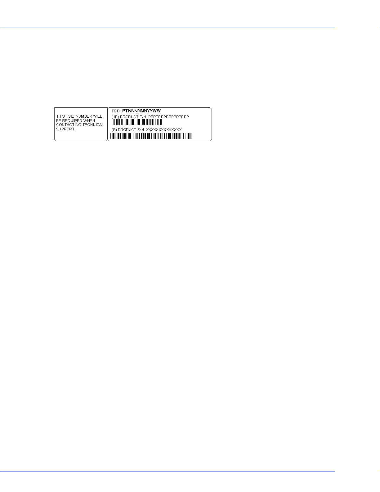
Technical Support Identification (TSID) Number
● Before contacting Technical Support, you need your unique 12-digit TSID number. The TSID number identifies your product
and support status.
● The TSID number is included on a white, bar-coded label, like this example:
● Affix a copy of the TSID label to the CD jacket so that you don’t lose it.
North America
● Visit our Web site at www.adaptec.com.
● Search the Adaptec Support Knowledgebase (ASK) at ask.adaptec.com for articles, troubleshooting tips, and frequently asked
questions for your product.
●
For information about Adaptec’s support options, call +1 408-957-2550,
24 hours per day, 7 days per week. To speak with a Technical Support Specialist,
● For Hardware products call +1 408-934-7274,
Monday to Friday, 5:00
● For RAID and Fibre Channel products call +1 321-207-2000,
Monday to Friday, 5:00
● For support via e-mail, submit your question at ask.adaptec.com.
●
You can order Adaptec products, including accessories and cables, by calling +1 408-957-7274.
www.adaptec.com/buy-cables.
Europe
● Visit our Web site at www.adaptec-europe.com.
● German: Call +49 89 43 66 55 22, Monday to Friday, 9:00 to 17:00, CET. For support via e-mail, submit your question at
ask-de.adaptec.com.
● French: Call +49 89 43 66 55 33, Monday to Friday, 9:00 to 17:00, CET. For support via e-mail, submit your question at
ask-fr.adaptec.com.
● English: Call +49 89 43 66 55 44, Monday to Friday, 9:00 to 17:00, GMT. For support via e-mail, submit your question at
ask.adaptec.com.
● You can order Adaptec cables online at www.adaptec.com/buy-cables.
Japan
● Visit our Web site at www.adaptec.co.jp.
● Call +81-3-3831-5190.
A.M. to 5:00 P.M., Pacific Time.
A.M. to 5:00 P.M., Pacific Time.
Or, you can order cables online at

● 4
Limited 3-Year Hardware Warranty
1. Adaptec, Inc. (“Adaptec”) warrants to the purchaser of this product that it will be free from defects in material and workmanship for
a period of three (3) years from the date of purchase. If the product should become defective within the warranty period, Adaptec, at
its option, will repair or replace the product, or refund the purchaser’s purchase price for the product, provided it is delivered at the
purchaser’s expense to an authorized Adaptec service facility or to Adaptec.
2. Repair or replacement parts or products will be furnished on an exchange basis and will either be new or reconditioned. All
replaced parts or products shall become the property of Adaptec. This warranty shall not apply if the product has been damaged
by accident, misuse, abuse or as a result of unauthorized service or parts.
3.
Warranty service is available to the purchaser by delivering the product during the warranty period to an authorized Adaptec
service facility or to Adaptec and providing proof of purchase price and date. The purchaser shall bear all shipping, packing and
insurance costs and all other costs, excluding labor and parts, necessary to effectuate repair, replacement or refund under this
warranty
4. For more information on how to obtain warranty service, write or telephone Adaptec at 691 South Milpitas Boulevard,
Milpitas, CA 95035, (800) 959-7274.
5. THIS LIMITED WARRANTY DOES NOT EXTEND TO ANY PRODUCT WHICH HAS BEEN DAMAGED AS A RESULT OF
ACCIDENT, MISUSE, ABUSE, OR AS A RESULT OF UNAUTHORIZED SERVICE OR PARTS.
6.
THIS WARRANTY IS IN LIEU OF ALL OTHER EXPRESS WARRANTIES WHICH NOW OR HEREAFTER MIGHT
OTHERWISE ARISE RESPECT TO THIS PRODUCT. IMPLIED WARRANTIES, INCLUDING THOSE OF
MERCHANTABILITY, FITNESS FOR A PARTICULAR PURPOSE AND NON-INFRINGEMENT SHALL (A) HAVE NO
GREATER DURATION THAN 3 YEARS FROM THE DATE OF PURCHASE, (B) TERMINATE AUTOMATICALLY AT THE
EXPIRATION OF SUCH PERIOD AND (C) TO THE EXTENT PERMITTED BY LAW BE EXCLUDED. IN THE EVENT THIS
PRODUCT BECOMES DEFECTIVE DURING THE WARRANTY PERIOD, THE PURCHASER’S EXCLUSIVE REMEDY SHALL
BE REPAIR, REPLACEMENT OR REFUND AS PROVIDED ABOVE. INCIDENTAL OR CONSEQUENTIAL DAMAGES,
INCLUDING WITHOUT LIMITATION LOSS OF DATA, ARISING FROM BREACH OF ANY EXPRESS OR IMPLIED
WARRANTY ARE NOT THE RESPONSIBILITY OF ADAPTEC AND, TO THE EXTENT PERMITTED BY LAW, ARE HEREBY
EXCLUDED BOTH FOR PROPERTY DAMAGE, AND TO THE EXTENT NOT UNCONSCIONABLE, FOR PERSONAL INJURY
DAMAGE
7. SOME STATES DO NOT ALLOW THE EXCLUSION OR LIMITATION OF INCIDENTAL OR CONSEQUENTIAL
DAMAGES FOR CONSUMER PRODUCTS, AND SOME STATES DO NOT ALLOW LIMITATIONS ON HOW LONG AN
IMPLIED WARRANTY LASTS, SO THE ABOVE LIMITATION OR EXCLUSIONS MAY NOT APPLY TO YOU.
8. This warranty gives you specific legal rights, and you may also have other rights which vary from state to state.
.
.

● 5
Regulatory Compliance Statements
Federal Communications Commission Radio Frequency Interference Statement
WARNING: Changes or modifications to this unit not expressly approved by the party responsible for compliance could void the user’s authority to
operate the equipment.
This equipment has been tested and found to comply with the limits for a Class B digital device, pursuant to Part 15 of the FCC rules. These limits are
designed to provide reasonable protection against harmful interference in a residential installation. This equipment generates, uses, and can radiate
radio frequency energy, and if not installed and used in accordance with the instruction manual, may cause harmful interference to radio
communications. However, there is no guarantee that interference will not occur in a particular installation. However, if this equipment does cause
interference to radio or television equipment reception, which can be determined by turning the equipment off and on, the user is encouraged to try to
correct the interference by one or more of the following measures:
■ Reorient or relocate the receiving antenna.
■ Increase the separation between equipment and receiver.
■ Connect the equipment to an outlet on a circuit different from that to which the receiver is connected.
■ Consult the dealer or an experienced radio/television technician for help.
■ Use a shielded and properly grounded I/O cable and power cable to ensure compliance of this unit to the specified limits of the rules.
This device complies with part 15 of the FCC rules. Operation is subject to the following two conditions: (1) this device may not
cause harmful interference and (2) this device must accept any interference received, including interference that may cause
undesired operation.
Adaptec, Inc.
Tes ted t o Comp ly
With FCC Standa rds
FOR HOME OR OFFICE USE
AAR-1430SA/AAR-1420SA/AAR-1220SA
European Union Compliance Statement
This Information Technology Equipment has been tested and found to comply with EMC Directive 89/336/EEC, as amended by 92/31/EEC
and 93/68/EEC, in accordance with:
● EN55022 (1998+A1:2000+A2:2003) Emissions
● EN55024 (1998+A1:2001+A2:2003) Immunity:
– EN61000-4-2 (1995) Electrostatic discharge: ±4 kV contact, ±8 kV air
– EN61000-4-3 (1996) Radiated immunity
– EN61000-4-4 (1995) Electrical fast transients/burst: ±1 kV AC, ±0.5 kV I/O
– EN61000-4-5 (1995) Surges ±1 kV differential mode, ±2 kV common mode
– EN61000-4-6 (1996) Conducted immunity: 3 V
– EN61000-4-11 (1994) Supply dips and variation: 30% and 100%
In addition, all equipment requiring U.L. listing has been found to comply with EMC Directive 73/23/EEC as amended by 93/68/EEC in
accordance with EN60950 with amendments A1, A2, A3, A4, A11.
Australian/New Zealand Compliance Statement
This device has been tested and found to comply with the limits for a Class B digital device, pursuant to the Australian/New Zealand standard
AS/NZS 3548 set out by the Spectrum Management Agency.
Canadian Compliance Statement
This Class B digital apparatus meets all requirements of the Canadian Interference-Causing Equipment Regulations.
Cet appareil numérique de la classe B respecte toutes les exigences du Règlement sur le matériel brouilleur du Canada.
Japanese Compliance (Voluntary Control Council Initiative)
This equipment complies to class B Information Technology equipment based on VCCI (Voluntary Control Council for Interface). This
equipment is designed for home use but it may causes radio frequency interference problem if used too near to a television or radio. Please
handle it correctly per this documentation.

Contents
About This Guide
What You Need to Know Before You Begin ................................................... 11
Terminology Used in this Guide...................................................................... 11
How to Find More Information....................................................................... 11
About Your HostRAID Controller
HostRAID Controller Features ........................................................................ 13
Array Level Features ................................................................................... 13
Upgrading the HostRAID Controller Firmware ............................................. 13
About the Adaptec 1430SA Controller ............................................................ 14
About the Adaptec 1420SA Controller ............................................................ 15
About the Adaptec 1220SA Controller ............................................................ 16
Kit Contents and
System Requirements
Kit Contents ...................................................................................................... 18
System Requirements........................................................................................ 18
Getting Started
Choosing a RAID Level..................................................................................... 20
Selecting Disk Drives ........................................................................................ 20
Disk Drives for Your Controller ................................................................20
Selecting Cables................................................................................................. 20
SATA Cables................................................................................................ 20
Installation Options .......................................................................................... 21
Basic Installation Steps ...............................................................................21
Installing with an Operating System.......................................................... 21
Installing on an Existing Operating System ..............................................21

Contents ● 7
Installing the HostRAID Controller
and Disk Drives
Before You Begin............................................................................................... 23
Installing the HostRAID Controller................................................................. 23
Connecting Disk Drives to SATA HostRAID Controllers.............................. 24
Checking Your Controller and Devices ........................................................... 24
Determining the Boot Controller..................................................................... 24
Next Steps.......................................................................................................... 24
Creating a Bootable Array
Setting the Boot Controller .............................................................................. 26
Creating an Array.............................................................................................. 26
Creating an Array with the ACU...................................................................... 26
Creating an Array with Adaptec Storage Manager.......................................... 27
Making Your Array Bootable ...........................................................................28
Installing the Driver and
an Operating System
Before You Begin............................................................................................... 30
Creating a Driver Disk ...................................................................................... 30
Installing with Windows................................................................................... 30
Installing with Red Hat Linux .......................................................................... 31
Installing with SUSE Linux............................................................................... 31
Installing with NetWare.................................................................................... 32
Installing the Driver on an
Existing Operating System
Before You Begin............................................................................................... 34
Creating a Driver Disk ...................................................................................... 34
Installing on Windows...................................................................................... 34
Installing on Red Hat or SUSE Linux ..............................................................35
Installing on NetWare....................................................................................... 35
Managing Your Storage Space
About Adaptec Storage Manager ..................................................................... 37
Installing Adaptec Storage Manager ................................................................37
About the HRCONF Command Line Utility .................................................. 37
About the ARC Utility ......................................................................................38
About the AFU .................................................................................................. 38
Which Utility Should I Use?............................................................................. 38

Contents ● 8
Understanding Adaptec Storage Manager
Features.............................................................................................................. 40
Overview............................................................................................................ 40
Physical Devices View................................................................................. 41
Logical Devices View ..................................................................................41
Changing How Drives are Displayed ............................................................... 41
Collapsed and Expanded Views ....................................................................... 42
Component Views............................................................................................. 43
Solving Problems
Troubleshooting Checklist ............................................................................... 45
Recovering from a Disk Drive Failure ............................................................. 45
Failed Disk Drive Protected by a Hot Spare.............................................. 45
Failed Disk Drive Not Protected by a Hot Spare ....................................... 46
Failure in Multiple Arrays Simultaneously................................................ 46
Disk Drive Failure in a RAID 0 Array........................................................ 46
Multiple Failures in the Same Array .......................................................... 46
Understanding RAID
RAID Technology Overview............................................................................. 48
Understanding Drive Segments .................................................................48
Stripe-unit Size............................................................................................ 48
Selecting a RAID Level and Tuning Performance..................................... 48
RAID 0 (Non-RAID Arrays) ............................................................................ 49
RAID 1 Arrays ................................................................................................... 50
RAID 10 Arrays ................................................................................................. 50
Using the ARC Utility
Introduction to the ARC Utility....................................................................... 52
Running the ARC Utility .................................................................................. 52
Creating and Managing Arrays ........................................................................ 52
Creating a New Array .................................................................................52
Managing Arrays......................................................................................... 54
Adding/Deleting Hotspares........................................................................ 56
Managing Bootable Arrays and Devices .................................................... 56
Configuring Disk Drives............................................................................. 56
ATAPI Support ...........................................................................................57
Using SATASelect .............................................................................................. 57
SATASelect Options.................................................................................... 58
Formatting and Verifying Disk Drives............................................................. 59

Contents ● 9
Using the AFU for DOS
Introduction ...................................................................................................... 61
System Requirements ................................................................................. 61
Compatibility .............................................................................................. 61
Running the AFU from the GUI ...................................................................... 62
Running the AFU from the Command Line ................................................... 62
HELP ........................................................................................................... 62
LIST .............................................................................................................62
SAVE............................................................................................................ 63
UPDATE...................................................................................................... 64
VERIFY........................................................................................................ 64
VERSION .................................................................................................... 65
Command Switches .................................................................................... 65
AFU Command Line – Step-by-Step ............................................................... 65
Safety Information
Electrostatic Discharge (ESD) ..........................................................................67
Technical Specifications
Environmental Specifications........................................................................... 69
DC Power Requirements .................................................................................. 69
Current Requirements ..................................................................................... 69
Glossary
Index

About This Guide
In this chapter...
What You Need to Know Before You Begin .......................................................................... 11
Terminology Used in this Guide............................................................................................ 11
How to Find More Information ............................................................................................ 11
1
This Installation and User’s Guide explains how to install your Adaptec
It also describes the utilities included in your controller kit, and provides a basic overview of
Serial ATA technology.
These HostRAID controller models are described in this Guide:
● Adaptec 1430SA, see page 14
● Adaptec 1420SA, see page 15
● Adaptec 1220SA, see page 16
®
Serial ATA controller.

What You Need to Know Before You Begin
You should be familiar with computer hardware, data storage, Redundant Array of
Independent Disks (RAID) technology, and the input/output (I/O) technology—SATA—used
by your HostRAID controller.
You should also be familiar with Direct Attached Storage (DAS) and Storage Area Network
(SAN) concepts and technology.
Terminology Used in this Guide
Because you can use your HostRAID controller to manage data storage in a variety of
configurations from DAS to SAN, the generic term “storage space” is used to refer to
controller(s) and disk drives being managed with Adaptec Storage Manager
utilities described in this Guide.
Many of the terms and concepts referred to in this Guide are known to computer users by
multiple names. This Guide uses these terms:
● Controller (also known as adapter, board, or card)
● Disk drive (also known as hard disk, hard drive, or hard disk drive)
Chapter 1: About This Guide ● 11
TM
or the other
● Array (also known as a container or logical drive)
The Adaptec Storage Manager User’s Guide refers to arrays as logical drives. Why?
Note:
Your HostRAID controller creates arrays, which your operating system (and Adaptec Storage
Manager) recognizes as logical drives.
How to Find More Information
You can find more information about your HostRAID controller and the software and utilities
included with it by referring to these documents:
● Readme.txt—Includes updated product information and known issues; located on the
HostRAID Installation CD.
● Adaptec Storage Manager User’s Guide—Describes how to install and use the Adaptec
Storage Manager software (see page 36); located on the Adaptec Storage Manager
Installation CD.
● Adaptec Storage Manager online Help—Describes how to use the Adaptec Storage Manager
software; accessible from the main window of Adaptec Storage Manager.

About Your HostRAID Controller
In this chapter...
HostRAID Controller Features.............................................................................................. 13
Upgrading the HostRAID Controller Firmware................................................................... 13
About the Adaptec 1430SA Controller.................................................................................. 14
About the Adaptec 1420SA Controller.................................................................................. 15
About the Adaptec 1220SA Controller.................................................................................. 16
This chapter provides an overview of standard HostRAID controller features, and describes the
unique features of your SATA HostRAID controller. It also explains how to upgrade your
controller with enhanced features.
2

HostRAID Controller Features
● Flash ROM for updates to controller firmware Adaptec Flash Utility (AFU), BIOS, and the
Array Configuration Utility (ACU).
● Event logging and broadcasting, including messaging for alphanumeric pagers.
● Support for Adaptec Metadata Format (AMF) allowing the migration of simple volumes
and arrays to Adaptec RAID controller cards.
● Multiple options for creating and managing RAID arrays—A full software application
(Adaptec Storage Manager), a BIOS-based utility, a command line utility, and a DOS
utility. See Managing Your Storage Space on page 36 for more information.
● Support for disk drive hot swapping.
● Support for disk drive enclosures with SAF-TE enclosure management hardware.
Array Level Features
Note: For more information, refer to the Adaptec Storage Manager User’s Guide or online
Help.
Chapter 2: About Your HostRAID Controller ● 13
● Support for RAID 0, 1, 10, and simple volume.
● Hot swap rebuild of fault tolerant arrays through the operating system.
● Support for automatic failover, so arrays are automatically rebuilt when a failed disk drive
is replaced (applies to redundant arrays in SES- or SAF-TE-enabled disk drive enclosures
only).
● Global hot spare protecting every fault tolerant array that the drive has enough available
capacity to protect.
● Support for RAID 0 migration.
Upgrading the HostRAID Controller Firmware
To upgrade the firmware on your HostRAID controller, see Using the AFU for DOS on page 60.
Chapter 2: About Your HostRAID Controller ● 14
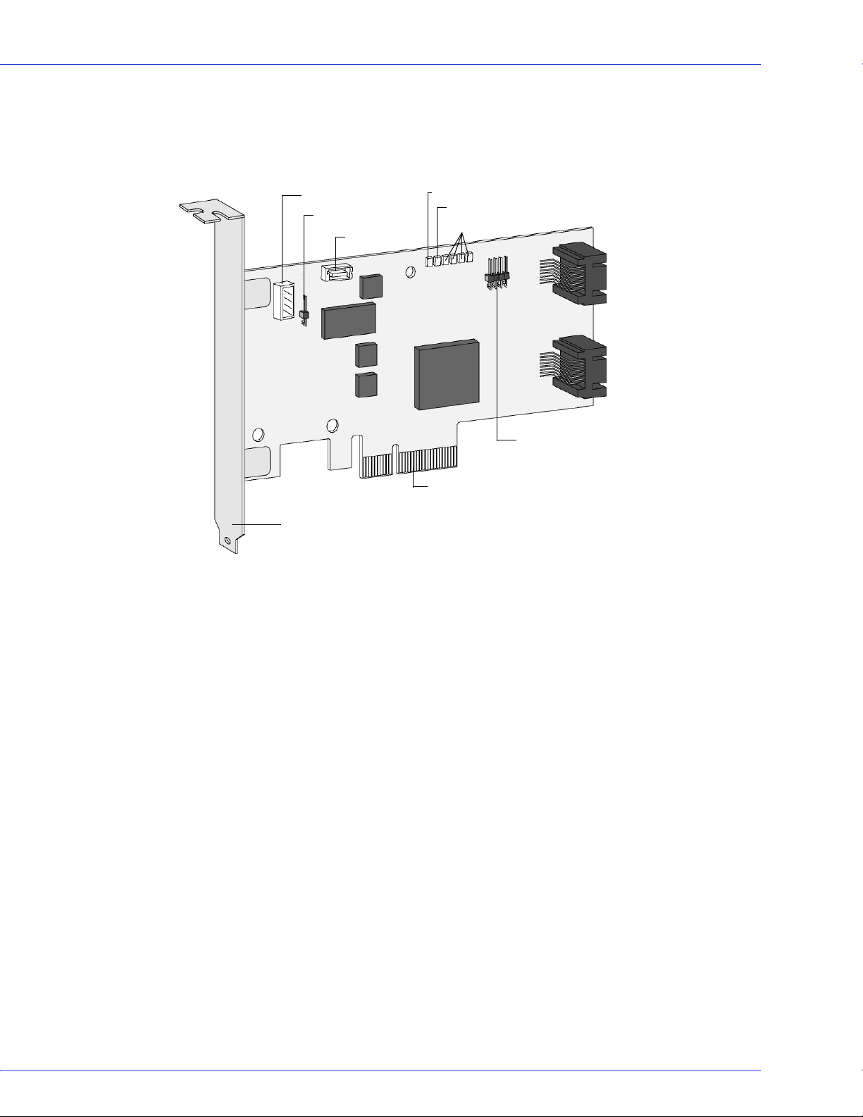
About the Adaptec 1430SA Controller
The Adaptec 1430SA is a low-profile 4-port PCIe SATA II HostRAID controller with these
features:
J1 Connector (I2C)
Aggregate LED
Activity LED
Mounting bracket
Power LED
Aggregate LED
Port Activity LED
Activity LED
PCIe connector
Form factor Low-profile
PCI compatibility PCIe x4
Ports 4 stacked
Connectors 4 internal
RAID levels 0, 1, 10
Simple volume Yes
Disk drives SATA I (1.5Gbps), SATA II (3.0Gbps)
Maximum number of disk drives 4
Hot spares Yes
Enclosure support Yes, SATA II Enclosure Management
using I2C connection
Native Command Queuing (NCQ) Yes
Automatic failover Yes
Audible alarm No
3 (top port)
2 (bottom port)
SATA ports
1 (top port)
0
(bottom port)
Chapter 2: About Your HostRAID Controller ● 15
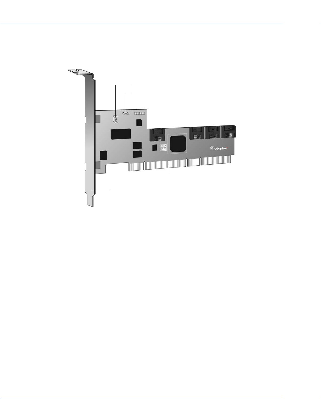
About the Adaptec 1420SA Controller
The Adaptec 1420SA is a low-profile PCI-X to 4 port SATA II HostRAID controller with these
features:
J1 Connector (I2C)
J2 Connector (Activity LED)
SATA ports
3
PCI-X connector
0
2
1
Mounting bracket
Form factor Low-profile
PCI compatibility PCI-X x1
Ports 4
Connectors 4 internal
RAID levels 0, 1, 10
Simple volume Yes
Disk drives SATA I (1.5Gbps), SATA II (3.0Gbps)
Maximum number of disk drives 4
Hot spares Yes
Enclosure support Yes, SATA II Enclosure Management
using I2C connection
Native Command Queuing (NCQ) Yes
Audible alarm No

Chapter 2: About Your HostRAID Controller ● 16
About the Adaptec 1220SA Controller
The Adaptec 1220SA is a low-profile PCIe to 2 port SATA II HostRAID controller with these
features:
0
SATA ports
1
PCIe connector
Mounting bracket
Form factor Low-profile
PCI compatibility PCIe
PCI bus width (max) 64-bit
PCI bus speed (max) 133 MHz
Ports 2
Connectors 2 internal
RAID levels 0, 1
Simple Volume Yes
Disk drives SATA I (1.5Gbps), SATA II (3.0Gbps)
Maximum number of disk drives 2
Hot spares Yes
Enclosure support No
Native Command Queuing (NCQ) Yes
Audible alarm No

Kit Contents and System Requirements
In this chapter...
Kit Contents............................................................................................................................ 18
System Requirements .............................................................................................................18
This chapter lists the contents of your HostRAID controller kit and the system requirements
that must be met for you to successfully install and use your controller.
3

Kit Contents
● Adaptec SATA HostRAID controller
● HostRAID Installation CD (bootable), including controller drivers, and this Guide
● Adaptec Storage Manager Installation CD (not bootable), including user guides for
Adaptec Storage Manager and the Adaptec HRCONF (HostRAID Configuration)
command line utility
● Readme Files
● Cables (type and quantity vary for cable information about your HostRAID controller, see
About Your HostRAID Controller on page 12)
● Low-profile bracket
● Serial ATA II 1430SA, 1420SA, 1220SA HostRAID Controllers Quick Start Guide
System Requirements
● PC-compatible computer with Intel Pentium, or equivalent, processor
● A motherboard with these features:
Chapter 3: Kit Contents and System Requirements ● 18
● Complies with the PCI Local Bus Specification, Revision 2.2 and higher.
● Supports multifunction devices where one of the devices is a PCI bridge.
● Large memory-mapped address ranges.
● One of these operating systems:
● Microsoft® Windows®2000, Server 2003, XP
● Red Hat Linux
● SUSE Linux
● Novell® NetWare®
For up-to-date operating system version support, refer to the Adaptec Web Site
Note:
at www.adaptec.com.
● At least 256 MB (or more) of RAM
● Available compatible PCI/PCI-X/PCIe slot (depending on your controller model-see About
Your HostRAID Controller on page 12)
● 40 MB of free drive space
● 16-bit SVGA color monitor with a resolution of at least 800 x 600
● CD drive (that is not part of the HostRAID you are installing)
● SATA interface cables

Getting Started
In this chapter...
Choosing a RAID Level.......................................................................................................... 20
Selecting Disk Drives.............................................................................................................. 20
Selecting Cables ...................................................................................................................... 20
Installation Options ............................................................................................................... 21
This chapter provides the basic information you need to set up your disk drives and arrays the
way you want them. It also describes the options you have for installing your HostRAID
controller and disk drives, and creating arrays for data storage.
Note:
Before you begin, familiarize yourself with your HostRAID controller’s physical
features and the RAID levels that it supports (see page 12).
4

Choosing a RAID Level
This section provides a brief overview of the RAID levels supported by your HostRAID
controller, including the minimum and maximum number of disk drives required by each.
RAID 0 (Non-redundant Array)—Stripes data across multiple disk drives. Improved
performance but no redundancy (see page 49).
RAID 1 Array—Created from two disk drives where one disk drive is a mirror of the other (the
same data is stored on each disk drive). Redundancy, but reduced capacity (see page 50).
RAID 10 Array—Built from two or more equal-sized RAID 1 arrays, stripes and mirrors data
across multiple disk drives. Redundancy and improved performance (see page 50). Not
supported on the 1220SA controller.
Use the table on page 49 to see how many disk drives you must connect to your HostRAID
controller to support the RAID level you want.
Selecting Disk Drives
When selecting disk drives for your RAID array, ensure that all the disk drives have the same
performance level. You can use different-sized disk drives in the array, but the array will be
limited to the capacity of the smallest and slowest disk drive.
Chapter 4: Getting Started ● 20
For more information, refer to the Adaptec Storage Manager User’s Guide or Adaptec Storage
Manager online Help.
Disk Drives for Your Controller
Your SATA controller supports both SATA (Serial ATA) I and II disk drives. For cable
information, see next section.
Selecting Cables
This section describes the cable options and requirements for your HostRAID controller.
SATA Cables
You need one straight connector to straight connector SATA cable for each disk drive you are
connecting to your Adaptec SATA RAID controller. SATA cables are included in the kit.
All SATA straight connector to straight connector cables have the same connectors, as shown in
the following figure, and the connectors are keyed so that you can’t insert them incorrectly.
Adaptec recommends using only Adaptec SATA cables. For more information or to purchase
cables, visit the Adaptec Web site at www.adaptec.com.

Installation Options
When you install your HostRAID controller, you can choose to create a bootable array and
then install your operating system and the controller driver on that array.
Alternatively, you can complete a standard installation, where the controller driver is installed
on an existing operating system.
Basic Installation Steps
This section describes the installation process. Follow the steps for the installation option
you’ve chosen.
Installing with an Operating System
1 Install and connect your controller and internal disk drives (see page 22).
2 Set the boot controller (see page 26).
3 Create a bootable array (see page 25).
4 Install your operating system and the driver (see page 29).
Chapter 4: Getting Started ● 21
5 Install Adaptec Storage Manager and begin to manage your data storage (see page 36).
Installing on an Existing Operating System
1 Install and connect your controller and internal disk drives (see page 22).
If your controller has an external connector, you can connect external disk drives as well
(or instead).
2 Install the controller driver (see page 34).
3 Install Adaptec Storage Manager and begin to manage your data storage (see page 36).

Installing the HostRAID Controller and Disk Drives
In this chapter...
Before You Begin .................................................................................................................... 23
Installing the HostRAID Controller...................................................................................... 23
Connecting Disk Drives to SATA HostRAID Controllers.................................................... 24
Checking Your Controller and Devices................................................................................. 24
Determining the Boot Controller.......................................................................................... 24
Next Steps ............................................................................................................................... 24
This chapter explains how to install your HostRAID controller, and how to install and connect
internal and external disk drives.
5
Before You Begin
● Read the Safety Information on page 67.
● Familiarize yourself with your HostRAID controller’s physical features and the RAID levels
that it supports (see page 12).
● Ensure that you have the right quantity of disk drives for the RAID level you want to use
for your arrays (see page 47).
● Ensure that you have the proper cables for your controller and disk drives (see page 12).
● If you have a low-profile computer cabinet, replace the original full-height bracket with the
low-profile bracket supplied in the controller kit.
Chapter 5: Installing the HostRAID Controller and Disk Drives ● 23
Caution:
!
Handle the controller by its bracket or edges only.
Installing the HostRAID Controller
This section describes how to install your HostRAID controller into your computer cabinet.
1 Turn off your computer and disconnect the power cord. Open the cabinet, following the
manufacturer’s instructions.
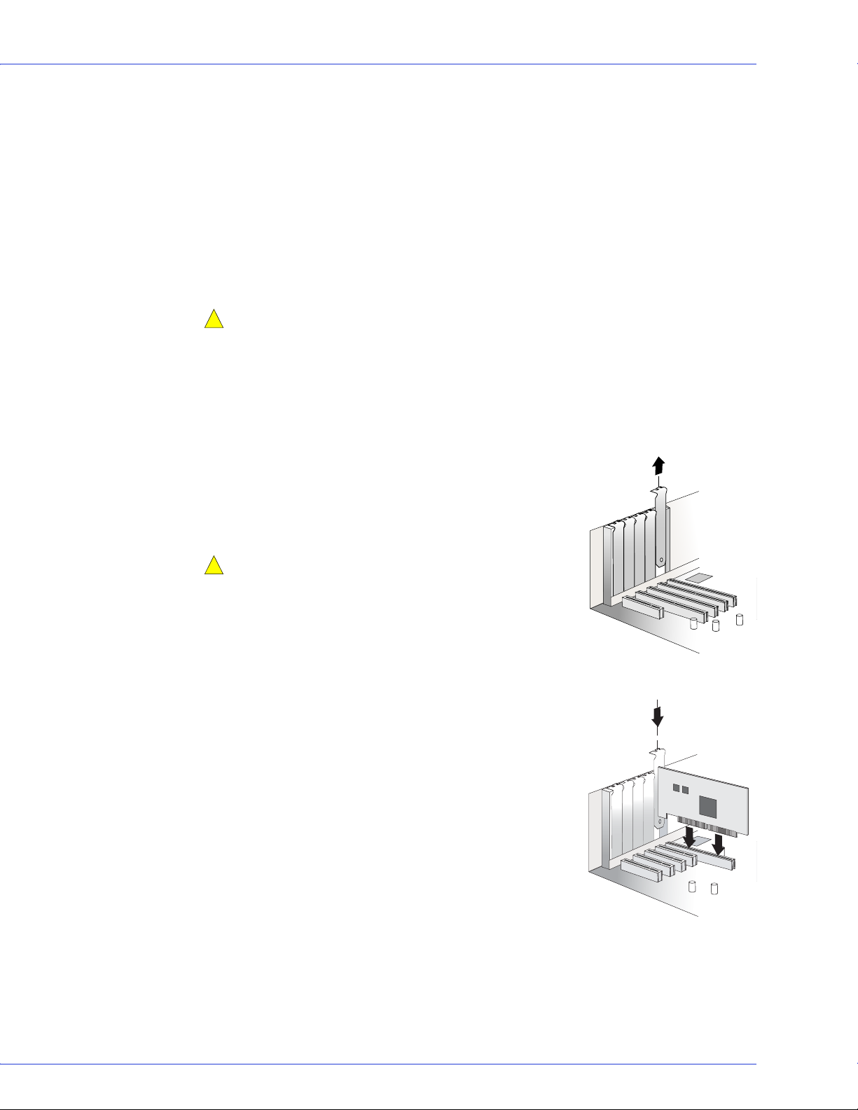
2 Select an available PCI or PCI-X expansion slot and remove
the slot cover, as shown at right. (see page 12.)
For the best performance, use the available 64-bit slot that’s
compatible with your HostRAID controller.
Caution:
!
handling the HostRAID controller.
3
As shown at right, insert the HostRAID controller into the
PCI or PCI-X expansion slot and press down gently but
firmly until it clicks into place. When installed properly, the
HostRAID controller should appear level with the
expansion slot.
4 Secure the bracket in the PCI slot, using the retention
device (for instance, a screw or lever) supplied with your
computer.
Touch a grounded metal object before
5 Connect your computer’s disk activity LED cable to the
LED connector on the controller (see page 12).
Ensure that the positive lead of the LED cable (usually a red
wire or a wire marked with a red stripe) is attached to pin 1.
6 Optional—Connect your HostRAID controller’s I2C
connector (not available on all models) to an I2C
connector on an internal backplane or enclosure, using an
I2C cable.
7 Install your disk drives, following the instructions on page 24.

Chapter 5: Installing the HostRAID Controller and Disk Drives ● 24
Connecting Disk Drives to SATA HostRAID Controllers
You can connect SATA disk drives to your HostRAID controller. There are no jumpers or
switches to set before installation. The cable ends are identical, so you don’t need to worry
about which end to attach to the controller and which end to attach to the drive.
The interface cable connectors, controller connectors, and disk drive connectors are all keyed
so that you can insert them in only one direction.
If you plan to build a bootable array using internal disk drives, ensure you install at least the
minimum number disk drives required to support the RAID level you want. See page 47 for
more information.
Checking Your Controller and Devices
Now that you have installed your controller and connected your Serial ATA disk drives, you are
ready to use the ARC utility to check your controller and devices, as described below:
1 Turn on y ou r com pu ter.
2 When the Adaptec banner appears, enter the ARC utility by pressing Ctrl+A.
3 If your drives have already been used in another system (even if not part of an array), select
Disk Utilities and format the drive. Otherwise, skip to Step 4.
If a drive appears to be missing, power down the computer and check the
Note:
connections.
4
Select SATASelect to verify the hardware configuration of the controller and the drives.
Verify that all drives and controllers are shown. If anything appears to be missing, power
down the computer and check the connections.
Determining the Boot Controller
Your Adaptec Serial ATA II RAID 1430SA, 1420SA, and 1220SA are bootable controllers. If
your computer already contains a bootable disk drive with an installed operating system, you
can set up your computer to boot a second operating system from the new controller.
To add a second bootable controller, you may need to enter Setup and change the hard disk
boot sequence so that the Adaptec Serial ATA II RAID controller heads the list. If Setup does
not allow this change, your system BIOS may not be configurable to allow the Adaptec Serial
ATA II RAID controller to act as a second boot device.
Next Steps
If you are installing the driver and an operating system onto a bootable array, continue with
Creating a Bootable Array on page 25.
If you are completing a standard installation onto an existing operating system, continue with
Installing the Driver on an Existing Operating System on page 33.
 Loading...