

Page 1

U
SER’S
G
UIDE
OVER FOR PREPRINTED SHELL
C
511589-00 REV D
D
URA
LAN™ F
AST ETHERNET
NICS
ANA™-69000/62000 F
AMILY
Page 2

R
Adaptec, Inc.
691 South Milpitas Boulevard
Milpitas, CA 95035
© 1999 Adaptec, Inc.
All rights reserved. Adaptec, and the Adaptec logo are
trademarks of Adaptec, Inc. which may be registered in
some jurisdictions.
Printed in Singapore
STOCK NO.: 512293-00, Rev. A DK4/99
Page 3

R
DuraLAN™ Fast Ethernet NICs
Including Duralink64™ Software
ANA-69000/62000 Family
User’s Guide
Page 4

Copyright
© 1999 Adaptec, Inc. All righ ts reserved. No part of this publication may be reproduced,
stored in a retrieval syste m , or t ransmitted in any form or by an y me ans, electronic, mechani cal, photocopying, recording or otherwise, without the prior written consent of Adaptec, Inc.,
691 South Milpitas Blvd., Milpitas, CA 95035.
Trademarks
Adaptec, the Adaptec logo, ANA, Duralink, and DuraLAN are trademarks of Adaptec, Inc.
which may be registered in some jurisdictions.
Windows NT is a trademark, Windows, Windows 95, and Windows 98 are registered trademarks of Microsoft Corporat ion in th e U. S. a nd ot he r countries used under license.
EtherChannel is a registered trademark of Cisco Systems, Inc.
NetWare is a registered trademark of Novell, Inc.
All other trademarks are owned by their respective owners.
Changes
The material in thi s d ocument is for inform at ion only and is subject to change without n otice.
While reasonable efforts have been made in the preparation of this document to assur e it s
accuracy, Adaptec, Inc. assumes no liability resulting from errors or omissions in this do cument, or from the use of the information contain ed herein.
Adaptec reserves the right to make changes in the product design without reservation and
without notification to its users.
Adaptec Technical Support and Services
If you have questions about installing or using your Adaptec product, check this user’s guide
first—you will find answers to most of your questions here. If you need further assistance,
please contact us. We offer the following support and information services:
Electronic Support
Technical infor mation, including product literature, answe rs to commonly asked quest ions,
information on software upgrades and other topics is available electronically through the
following:
■ Adaptec World Wid e Web ( WWW) site at
■ File Transfer Protocol (FTP) server at
■ Adaptec USA Bulletin Board Se rvi ce (BBS) at 408-945-7727; supports up to 28,800 bps
(bits per second), 8 data bits, 1 stop bit, no parity. No product literature is available on the
Adaptec BBS.
■ Interactive Fax System at 303-684 -3400; available 24 hours a day, 7 days a week.
http://www.adaptec.com
ftp.adaptec.com
.
ii
.
Page 5

Technical and Product Support
■ For technical support and information about many of Adaptec’s electronic support ser-
vices, call 800-959-7274 or 408-945-2550, 24 hours a day, 7 days a week. The system
prompts you with questions regarding your problem and then provides step-by-step troubleshooting instructions.
■ To submit your electronic mail message to Adaptec Technical Support use the product sup-
port information Webmail form at http://www.adaptec.com / s upport/webmail.html.
■ To speak with a product support representative, call 408-934-7274, M–F, 6:00
P.M
5:00
., Pacific Time. After hours, on weekends, and on holidays, product support is also
A.M
. to
available for a fee at 800-416-8066.
Sales and Ordering Information
■ For sales information, call 800-959-7274 or 408-945-2550, M–F, 6:00
Pacific T ime.
■ To order Adaptec software and SCSI cables, call 800-442-7274 or 408-957-7 274,
M-F, 6:00
■ To request additional documentatio n for Adaptec products, call 800-9 34-2766 or
510-732-3829, M–F, 6:00
A.M
. to 5:00 P.M., Pacific Time.
A.M
. to 5:00 P.M., Pacific Time.
A.M
. to 5:00 P.M.,
Class B Device Certification Statements
Federal Communications Commission Radio Frequency Interference Statement
WARNING: Changes or modifications to this unit not expressly approved by the party responsible for compliance could void the user’s authority to operate the equipment.
This equipment has been tested and found to comply with the limits for a Class B digital device, pursuant to
Part 15 of the FCC rules. These limits are designed to provide reasonable prot ecti on again st harm ful inte r ference in a residential installation. This equipment generates, uses, and can radiate radio frequency energy,
and if not installed and used in accordance with the instruction manual, may cause harmful interference to
radio communications. However, there is no guarantee that interference will not occur in a particular installation. However, if this equipment does cause interference to radio or television equipment reception, which
can be determined by turning the equipment off and on, the user is encouraged to try to correct the interference by one or more of the following measures:
Reorient or relocate the receiving antenna.
■
Increase the separation between equipment and receiver.
■
Connect the equipment to an outlet on a circuit different from that to which the receiver is connected.
■
Consult the dealer or an experienced radio/television technician for help.
■
Use a shielded and properly grounded I/O cable and power cable to ensure compliance of this unit to the
■
specified limits of the rules.
iii
Page 6

This device complies with part 15 of the FCC rules. Operation is subject to the following two conditions: (1)
this device may not cause harmful interference and (2) this device must accept any interference received,
including interference that may cause undesired operation.
Adaptec, Inc.
ANA-62011
ANA-69011
ANA-62022
ANA-62044
Tested To Comply With FCC Standards
FOR HOME OR OFFICE USE
Canadian Compliance State ment
This Class B digital apparatus meets all requirements of the Canadian Interference-Causing Equipment
Regulations.
Cet appareil numérique de la classe B respecte toutes les exi gen ces du Règlement sur le matérial brouilleur
du Canada
European C om pliance Statemen t
WARNING: This is a Class B product. In domestic environments this product may cause radio interference
in which case the user may be required to take adequate measures.
Safety Standards
These products meet the following national and international regulations:
■ UL 1950 Standard for Safety of Information Processing and Business Equipment
■ IEC 950 Safety of Information Technology Equipment in Electrical Business Equipment
■ CAN/CSA-C22.2 # 950 Safety of Information Technology Equipment including Electrical Business
Equipment
To ensure safe operating conditions, it is recommended that these products be installed in UL Listed
computers.
iv
Page 7

Limited Warranty
SOFTWARE. Adaptec, Inc. warrants to you that for a period of ninety (90) days from the date you receive
this software Product the magnetic media contains an accurate reproduction of the Software. This limited
warranty covers only the original user of the Product. If the Product media should become defective within
the warranty period, Adaptec at its option, will repair or replace the Product media , prov ided it is deliver ed
at your expense to Adaptec as provided below. Adaptec does not warrant that the product will be free from
error or will meet your specific requirements. Except for the warranties set forth above, the Product is
licensed “AS IS”, and ADAPTEC DISCLAIMS ALL OTHER WARRANTIES, EITHER EXPRESS OR
IMPLIED, INCLUDING BUT NOT LIMITED TO IMPLIED W ARRANTIES OF MERCHANTABILITY
AND FITNESS FOR A PARTICULAR PURPOSE.
HARDWARE . Adaptec, Inc. warrants to the original purchaser of this hardware Pr oduct that it will be free
from defects in workmanship and materials, under normal use and service, for the lifetime of the personal
computer in which it is installed from the date of purchase from Adaptec or its authorized dealer. In order
for this warranty to be valid, this Product must remain in its original personal computer and be registered
with Adaptec within one year of purchase. Otherwise, Adaptec warrants to the original purchaser of this
Product that it is to be free from defects in workmanship and materails, under normal use and service, for a
period of five (5) years from the date of purchase from Adaptec or an authorized dealer. Should this Product,
in Adaptec’s opinion, fail to meet this warranty during the applicable warranty period, Adaptec will, at its
expense and option, repair the defective Product or part or replace the defective item with an equivalent
product or part, or refund the purchase price. All returned Products will become the property of Adaptec. At
Adaptec’s option, replacement Products or parts may be new or reconditioned. Any replaced Product or part
has a ninety (90) day warranty or the remainder of the initial warranty period, whichever is longer. Such
remedy is your sole and exclusive remedy for breach of the above warranty.
LIMITED WA RR ANTY SERVICE. Products requiring limited warranty service during the applicable war-
ranty period should be delivered to Adaptec’s U.S. headquarters with proof of purchase. Products returned
to Adaptec must be pre-authorized with a Return Material Authorization (RMA) number marked on the out-
side of the package, and packaged in the original (or equivalent) packaging material. If the delivery is by
mail, you agree to insure the Product or assume the risk of loss or damage in transit. You also agree to pre-
pay shipping charges to Adaptec. The repaired or replaced item, or refund, will be shipped to the Customer,
at Adaptec’s expense, not later than thirty (30) days after receipt by Adaptec.
GENERAL. This limited warranty does not extend to any Product which has been damaged as a result of
accident, misuse, abuse, or as a result of unauthorized service or parts. Incidental or consequential damages,
including without limitation loss of data, arising from breach of any express or implied warranty are not the
responsibility of Adaptec and, to the extent permitted by law, are hereby excluded both for property damage,
and, to the extent not unconscionable, for personal injury damage. Some states do not allow the exclusion or
limitation of incidental or consequential damages for consume r produ ct s, so the above limitation or exclu-
sion may not apply to you. This warranty gives you specific legal rights, and you may also have other rights
which vary from state to state.
For more information on how to obtain warranty service, write or telephone Adaptec at 691 South Milpitas
Boulevard, Milpitas, CA 95035, (800) 959-7274.
v
Page 8

Page 9

▼ ▼ ▼ ▼
Part 1 Introduction to DuraLAN
1 Getting Started
System Requirements ..............................................................1-2
Hardware Requirements ...................................................1-2
Software Requirements .....................................................1-2
Fast Ethernet ........................................ ..... ...... ...... ...................1-3
Adaptec DuraLAN NICs ..........................................................1-3
Duralink64 Failover .................................................................1-6
Duralink64 Port Aggregation ...................................................1-7
FEC (Fast EtherChannel) .........................................................1-8
Advisories ............................................................. ...................1-9
2 Introduction to Duralink64
Port Aggregation
Traditional Network Configurations ........................................2-2
Servers with Duralink64 Port Aggregation ...................... ...... ..2-5
Duralink64 Port Aggregation Example ............................2-5
Contents
Part 2 Installing the
DuraLAN NIC
3 DuraLAN NIC Installation
Important Note for Windows 95 Users! ...................................3-2
Installing the Appropriate NIC ................................................3-3
Installing the DuraLAN NIC ...................................................3-4
vii
Page 10

DuraLAN Fast Ethernet NICs User’s Guide
Connecting the Network Cable ............................................. ...3-6
Installing the Appropriate NIC Driver .....................................3-7
4 Network Configuration Examples
Network Without Duralink64 Failover Protection ..................4-2
Single Hub or Switch on an Ethernet Segment .......................4-3
Dual Hubs ...................................................... ..........................4-4
Dual Hubs with an Ethernet Switch ...................................... ...4-5
Dual Hubs with Routers ...........................................................4-6
Dual Hubs with a Four-Port NIC .............................................4-7
Part 3 The DuraLink64
Driver for Windows
5 Duralink64 Driver Installation for Windows
Before You Begin ....................................................................5-2
Note on DuraLAN NIC Ports ...........................................5-2
Installing the DuraLAN Driver ................................................5-3
Windows NT 4.0 ..............................................................5-3
Windows NT 3.51 ............................................................5-6
Windows 98 ......................................................................5-8
Windows 95 ......................................................................5-9
Windows 95 OSR2 .................................................... 5-9
Windows 95 OSR1 .................................................. 5-10
Installation Tips .....................................................................5-11
Windows 95 ....................................................................5-11
Windows 98 ....................................................................5-12
Windows Clients Using Novell Client32 .......................5-12
Removing Previously Installed Drivers .................................5-13
Windows NT 4.0 ............................................................5-13
Windows NT 3.51 ..........................................................5-14
Windows 98 and 95 OSR1/OSR2 .................................. 5-14
viii
Page 11

6 Duralink64 Standard
Driver for Windows
Configuring the Standard Driver Ports
in Windows NT 4.0 and 3.51 ................................................6-2
Configuring the Ports in Windows 98/95 ................................6-4
7 Duralink64 Failover for Windows NT
Configuring the Ports ...............................................................7-2
Creating the Failover Pair ........................................................7-3
Windows NT 4.0 ...............................................................7-3
Windows NT 3.51 .............................................................7-6
Monitoring Failover Pairs ........................................................7-8
Note on DuraLAN NIC Ports ..................................................7-8
8 Duralink64 Port Aggregation
for Windows NT
Configuring the Ports ...............................................................8-2
Creating Port Aggregation Groups ..........................................8-4
Creating Fast EtherChannel Groups ........................................8-8
Assigning the TCP/IP Address ..............................................8-11
Modifying Groups ..................................................................8-13
Renaming Groups ...........................................................8-13
Adding or Removing Ports .............................................8-14
Checking System Status .........................................................8-17
Understanding the Status Tab .........................................8-18
Field Descriptions ....................................................8-18
Viewing the Groups .................................................8-19
Windows NT Performance Monitor ......................................8-20
Contents
ix
Page 12

DuraLAN Fast Ethernet NICs User’s Guide
Part 4 The Duralink64
Driver for NetWare
9 Duralink64 Standard Driver for NetWare
Before you Begin .....................................................................9-2
Note on NetWare ....................................................... ..... ...... ...9-2
Install of Duralink64 Driver during
NetWare 5.0 Operating System
Installation ............................................................................9-3
Installing the NetWare Standard Driver ..................................9-4
Configuring the Ports ...............................................................9-5
Assigning the Protocols ...........................................................9-7
Viewing the Configuration .................................................... 9-10
Restarting the Server ..............................................................9-11
Troubleshooting Tip .......................................................9-11
Removing Drivers ............................... ...................................9-12
Removing the DuraLAN Standard Driver ......................9-12
10 Duralink64 Failover
for NetWare
Before you Begin ...................................................................10-2
Note on NetWare ....................................................... ..... ...... .10-2
Installing the NetWare Failover Driver .................................10-3
Configuring the Ports .............................................................10-4
Creating the Failover Pairs ....................................................10-6
Assigning the Protocols .........................................................10-9
Viewing the Configuration ..................................................10-12
Copying and Saving the Configuration ...............................10-13
Viewing the System Status ..................................................10-14
Element Descriptions ....................................................10-15
F Keys ...................................................................10-15
Modifying the Driver Configuration ...................................10-16
Removing Drivers ................................................................10-17
Removing the Duralink64 Failover Driver ...................10-17
x
Page 13

Contents
11 Duralink64 Port Aggregation for NetWare
Before you Begin ...................................................................11-2
Note on NetWare ...................................................................11-2
Installing the NetWare Port Aggregation Driver ...................11-3
Configuring Ports ...................................................................11-4
Creating Port Aggregation Groups ........................................11-6
Creating Fast EtherChannel Groups ......................................11-9
Assigning Protocols .............................................................11-12
Verifying Configuration .......................................................11-15
Copying and Saving the Configuration ........................11-16
Viewing System Status ........................................................11-17
System Status Data .......................................................11-17
Setting Time Intervals ...................................................11-18
Modifying Driver Configurations ........................................11-18
Removing Drivers ...................................................... ..........11-19
Removing the Duralink64 Port Aggregation Driver ....11-19
12 Installing Duralink64 NetWare Client
Installing Novell Client32 ......................................................12-2
DOS ................................................................................12-2
Selecting Options .............................. .......................12-3
Editing startnet.bat ...................................................12-4
Connecting Clients to the NetWare Server .............12-4
Windows .........................................................................12-5
Connecting Clients to the NetWare Server .............12-5
Connecting Clients to the NetWare Failover Server ..............12-6
Connecting Clients to the NetWare
Port Aggregation Server .....................................................12-7
xi
Page 14

DuraLAN Fast Ethernet NICs User’s Guide
Part 5 Appendices
A Cables and LEDs
Connection Types ................................................ ...... ..... ...... ..A-2
Full Duplex Support ........................................................A-2
Cable Requirements ................................................................A-3
Straight-through Cable ............................................................A-4
Pinout and Color Requirements .............................................. A-5
Diagnostics Loop-Back Cable .........................................A-5
Diagnostic LEDs .....................................................................A-6
LED Functions ....................... ...... ...... ..... ......................... A-7
B Troubleshooting Tips
Isolating Faulty Hardware ...................................................... B-2
Troubleshooting ...................................................................... B-2
Configuring the BIOS .............................................................B-4
Frequently Asked Questions ................................................... B-5
Duralink64 Software And DuraLAN NICs -
General Questions ........................................................ B-5
Duralink64 v4.2 Failover Software Questions ................B-7
Duralink64 v4.2 Port Aggregation Software Questions .. B-8
Duralink64 v4.2 Windows NT - General Questions ..... B-10
Duralink64 v4.2 Windows 95 and Windows 98 -
General Questions ...................................................... B-11
Windows 95 ............................................................B-11
Windows 98 ............................................................B-12
Duralink64 v4.2 NetWare - General Questions ............ B-12
C Duralink SNMP Agents
Monitoring the NICs by SNMP ..............................................C-2
SNMP Support ........................................................................C-2
xii
Page 15

D The Diagnostics Utility
Running the Diagnostics ....................................... ..... .............D-2
From the Hard Drive ........................................................D-2
From the Floppy Drive ....................................................D-2
Diagnostic Tests ......................................................................D-3
Index
Contents
xiii
Page 16

Page 17

▼ ▼ ▼ ▼
Part 1
Introduction to DuraLAN
Page 18

Page 19

▼▼▼▼
Getting Started
In This Chapter
System Requirements 1-2
Fast Ethernet 1-3
Adaptec DuraLAN NICs 1-3
Duralink64 Failover 1-6
Duralink64 Port Aggregation 1-7
FEC (Fast EtherChannel) 1-8
Advisories 1-9
1
This user’s guide describes how to install and configure Adaptec
DuraLAN™ Fast Ethernet network interface cards (NICs). Please
review the system requirements before you begin.
User’s guide summary:
■
Part 1,
Adaptec DuraLAN NIC.
■
Part 2,
and configure the DuraLAN Standard NIC driver in NetWare
and Windows
■
Part 3,
Duralink64 Failover adds v alue to your network and provides
installation instructions for Windows
servers.
Introduction to DuraLAN
Installing the DuraLAN NIC
environments.
The DuraLink64 Driver for Windows
, describes how to install your
, describes how to install
NT and NetWare-based
, describes how
1-1
Page 20

DuraLAN Fast Ethernet NICs User’s Guide
■ Part 4,
The Duralink64 Driver for NetWare
, describes how to
create a virtual port by grouping ports to maximize bandwidth
for your mission-critical applications.
■ Part 5,
Appendices
, provides supplemental information that
may be required for a proper installation.
System Requirements
Hardware Requirements
The minimum hardware system requir ements for using the Adaptec
DuraLAN NIC are as follows:
System Component Requirements
NIC
Two and Four Port NICs
■ Available bus mastering PCI slot.
■ The most recent PCI system BIOS is
recommended.
■ Intel x86 platform with single or
multiprocessor.
■ 16-MByte RAM.
■ System BIOS supporting PCI-to-PCI
bridge chip.
■ Multiport NICs require PCI 2.1
compliant bus.
Software Requirements
The minimum software system requirements are as follows:
1-2
Windows
■
Windows
NetWare
■
—Windows NT 3.51 or 4.0 Workstation or Server,
95, or Windows 98.
—NetWare 4.x or 5.0.
Page 21

Getting Started
Fast Ethernet
Fast Ethernet is a networking standard defined by the Institute of
Electrical and Electronic Engineers (IEEE) in the IEEE 802.3u
Specification. Fast Et he rnet runs at 100 Mbps, or at 200 Mbps in Full
Duplex mode.
Fast Ethernet uses the same Carrier Sense Multiple Access with
Collision Detection (CSMA/CD) architecture used on 10BASE-T
and 10BASE-2 10 Mbps network specifications, which allows for
easy integration with existing networks.
Adaptec DuraLAN NICs
Note: 64-bit NICs will also work in 32-bit PCI slots.
Adaptec provides the following PCI 10/100 DuraLAN Fast Ethern et
NIC models:
■ ANA-69011/
TX
Single32™—a single-port 32-bit NIC supporting
autosensing between 10 and 100-Mbps line speeds.
Single RJ-45
Por
t
32-bit PCI 2.1 Bus
Figure 1-1. ANA-69011
TX
/
Single32™
DuraLAN NIC
1-3
Page 22

DuraLAN Fast Ethernet NICs User’s Guide
■
ANA-62011/TX Single64™—a single-port 64-bit/32-bit NIC
supporting autosensing between 10 and 100-Mbps line
speeds.
Single RJ-45 Port
64-bit PCI 2.1 Bus
Figure 1-2. ANA-62011
■ ANA-62022—a two-port NIC that offers two high-performance
/TX Single64
DuraLAN NIC
10/100 Fast Ethernet ports on a single 64-bit/32-bit NIC. Each
port runs at independent speeds for maximum flexibility. This
NIC supports Full Duplex to deliver speeds up to 400-Mbps
cumulative throughput.
RJ-45 Port 1
RJ-45 Port 2
64-bit PCI 2.1 Bus
Figure 1-3. ANA-62022 DuraLAN NIC
1-4
Page 23

Getting Started
■
ANA-62044—a four-port NIC that offers four high performance
10/100 Fast Ethernet ports on a single 64-bit/32-bit NIC. Each
port runs at independent speeds for maximum flexibility. This
NIC supports Full Duplex to deliver speeds up to 800-Mbps
cumulative throughput.
RJ-45 Port 1
RJ-45 Port 2
RJ-45 Port 3
RJ-45 Port 4
Figure 1-4. ANA-62044 DuraLAN NIC
1-5
Page 24

DuraLAN Fast Ethernet NICs User’s Guide
Duralink64 Failover
Duralink64 Failover software provides protection from network-link
failures on Fast Ethernet servers running mission-critical
applications. During a port failure, Duralink64 Failover keeps the
connection to the server live by moving all traffic on the affected
segment to a backup port. When a failur e is detected on the primary
port, that port is disabled and the backup port takes over to continue
data transmission, keeping the connection running without
interruption.
Duralink64 Failover is often used in a troubled environment to
provide failover capabilities when any of the following conditions
exist:
■ An Ethernet link loss
■ A watchdog timer expires
■ An abnormal hardware interrupt occurs
■ Abnormal Send/Receive counters, such as too many collisions
or errors occur on the segment
Duralink64 Failover supports Windows NT 4.0 and 3.51, and Novell
NetWare 4.x and 5.0 based servers.
Duralink64 Failover is compatibl e with Adaptec ANA
TX
and ANA-6201 1/
single-port NICs, ANA-62022 two-port NICs,
and ANA-62044 four-port NICs.
™
-69011/TX
1-6
Page 25

Getting Started
Duralink64 Port Aggregation
Duralink64 Port Aggregation is a softw are package th at provides
network path redundancy and increased bandwidth for Fast
Ethernet servers running mission-critical applications. Duralink64
Port Aggregation works by load balancing the throughput over
multiple ports.
With Duralink64 Port Aggregation, you can create a virtual port by
grouping multiple ports together. This grouping distributes the
network load by sharing the resources of all ports in a group. In the
Port Aggregation group, one port becomes the “primary” port and
its MAC address is given to the protocol. Thus, the group behaves as
a single interface, allowing the software to manage the combined
resources of the group efficiently. In the event of a port failure, the
remaining ports carry the load and keep the network running and
uninterrupted.
Duralink64 Port Aggregation supports Windows NT 4.0 and 3.51,
and Novell NetWare 4.x and 5.0 -based servers.
Duralink64 Port Aggregation is compatible with Adaptec
TX
ANA-69011/
dual-port NICs, and ANA-62044 quad-port NICs.
and ANA-62011/TX single-port NICs, ANA-62022
1-7
Page 26

DuraLAN Fast Ethernet NICs User’s Guide
FEC (Fast EtherChannel)
Fast EtherChannel® (FEC) is a technology developed by Cisco
Systems based on standard Fast Ethernet used in parallel to pr ovide
the additional bandwidth network backbones required today. FEC
combines two or four Fast Ethernet links to single logical connection
capable of carrying 800 Mbits/sec of aggregate full-duplex
throughput. In addition to scalable bandwidth , the technology also
provides fault tolerance and resiliency, protecting the network from
outages due to failed links.
Fast EtherChannel allows grouping of DuraLAN ports or NICs
allowing full utilization of available band width (up to
800 Mbits/sec). Up to four single port NICs, 2 two port NICs, or 1
four port NIC can be grouped. This technology also provides load
balancing and management of each link by distributing traffic across
multiple links in the channel. In addition, FEC technology provides
redundancy in the event of link failure.
Duralink64 v4.2 software and all of Adaptec DuraLAN NICs
support Fast EtherChannel technology, allowing redundancy and
high-speed aggregation between switches and servers.
Fast EtherChannel is available on select Cisco Catalyst switches and
Cisco routers.
For additional information on Cisco’s Fast EtherChannel technology ,
visit the Cisco Systems web site:
http://www.cisco.com/warp/public/729/fec
1-8
Page 27

Getting Started
Advisories
This document includes three kinds of advisories.
Note: Notes are reminders, tips, or suggestions that might
simplify the procedures included in this document.
Caution: Cautions alert you to actions that might cause damage
to your system or your data.
!
WARNING: Warnings alert you to actions that might cause
injury to you or someone else.
To avoid injury to people or damage to equipment and data, be sure
to follow the cautions and warnings in this document. Adaptec does
not claim to have included in this document every condition or
situation that might require a caution or warning notice. Be sure to
consult the documentation for your computer and any connected
equipment when you are installing the equipment or changing its
configuration.
❒
WARNING: Always use caution when handling electrical
equipment!
1-9
Page 28

Page 29

2
▼▼▼▼
Introduction to Duralink64 Port Aggregation
In this Chapter
Traditional Network Configurations 2-2
Servers with Duralink64 Port Aggregation 2-5
This chapter compares traditional Ethernet configurations to
Ethernet servers using Duralink64 Port Aggregation. These
examples show the impact Duralink64 Port Aggregation has on
network performance and hardware investment.
2-1
Page 30

DuraLAN Fast Ethernet NICs User’s Guide
Traditional Network Configurations
The following three examples show some typical configuration
methods.
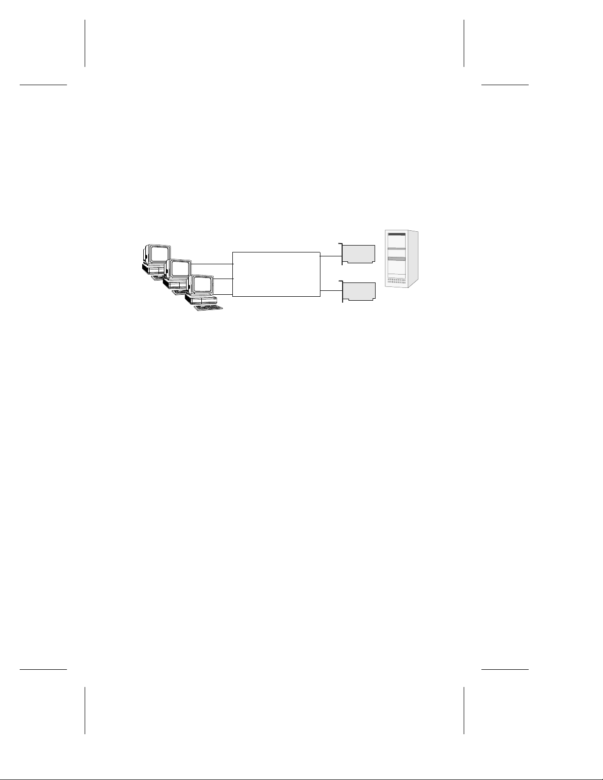
The figure below illustrates a single segment server initialized at 100
Mbps with Full Duplex Ethernet (FDE). In this example, the
segmented server is limited to 200 Mbps. In addition, if the
connection to the server fails, the network may go down.
Clients
Central switching area
with lines to workgroups
Ethernet Switch
Server
Router
2-2
Clients
Ethernet Switch
Figure 2-1. Single Segment Server
Page 31

Introduction to Duralink64 Port Aggregation
The next traditional method provides network Fault Tolerance
through doubling the hardware and addition of a special version of
NetWare (SFT3). Data is kept curr ent between servers via a Mirr ored
Server Link (MSL). In the illustration below, one server is active
while the other is ready to take over all duties if the other fails.
Primary Server
Clients
Central switching area
with lines to workgroups
Ethernet Switch
MSL
Secondary Server
Figure 2-2. Fault Tolerance Using NetWare
2-3
Page 32

DuraLAN Fast Ethernet NICs User’s Guide
The illustration below illustrates a configuration with Windows NT
Server (Wolfpack).
Clients
Central switching area
with lines to workgroups
Ethernet Switch
Storage
Devices
Figure 2-3. Fault Tolerance Using NT
Primary Server
Ethernet
Link
Secondary Server
2-4
Page 33

Introduction to Duralink64 Port Aggregation
Servers with Duralink64 Port Aggregation
A server with Duralink64 Port Aggregation can use up to 12
Adaptec PCI Fast Ethernet ports in one aggregated group (at 1.2
Gbps per group).
If any of the contributing members of a specific aggregated group
should fail, that member is e xcluded from the group. The remaining
ports balance the existing load.
Duralink64 Port Aggregation Example
The illustration below illustrates a server with 12 ports from three
Adaptec ANA-62044 NICs. With this configuration, the server has a
cumulative bandwidth of 1.2 Gbps on its single virtual segment (200
Mbps per port). Further, the network segment is fault tolerant,
enabling the network to remain alive shoul d any port fail.
Clients
❒
Central switching area
with lines to workgroups
Ethernet Switch
6 ports
6 ports
Ethernet Switch
Shared workgroup hub
Ethernet Hub
Figure 2-4. Port Aggregation
Server
3x ANA-62044
2-5
Page 34

Page 35

▼ ▼ ▼ ▼
Part 2
Installing the
DuraLAN NIC
Page 36

Page 37

3
▼▼▼▼
DuraLAN NIC Installation
In This Chapter
Important Note for Windows 95 Users! 3-2
Installing the Appropriate NIC 3-3
Installing the DuraLAN NIC 3-4
Connecting the Network Cable 3-6
Installing the Appropriate NIC Driver 3-7
This chapter provides instructions on installing your Ada ptec
DuraLAN NIC. If you are a Windows 95 user, please read
Note for Windows 95 Users!
before proceeding with this installation.
Important
3-1
Page 38

DuraLAN Fast Ethernet NICs User’s Guide
Important Note for Windows 95 Users!
Before installing the DuraLAN NIC, verify which version of
Windows 95 is installed. (You either have OSR1 or OSR2.) You will
need to know which version you have if you install the DuraLAN
Standard driver. Use the following instructions for help:
Start Windows 95.
1
.
Start
menu, point to
System
Windows 95 Versions
4.00.950 OSR1
4.00.950A OSR1
4.00.950B OSR2
4.00.950C OSR2
Installing the DuraLAN NIC
Click the
2
Panel
Double-click the
3
version of Windows 95.
Click OK to exit the General tab.
4
Shut down the system, and then turn OFF power.
5
Continue with
6
Settings
icon. The General tab displays your
, and then click
on page 3-4.
Control
3-2
Page 39

DuraLAN NIC Installation
Installing the Appropriate NIC
The following table describes which DuraLAN NIC to install for
your operating system and Adaptec driver.
Duralink64 Port
DuraLAN
Standard
driver
Duralink64
Failover
Aggregation/Cisco’s
Fast Ethernet
Channel
/TX
/TX
/TX
/TX
/TX
/TX
Windows 95
1
OSR1
Windows 95
1
OSR2
ANA-69011
ANA-62011
ANA-62022
ANA-62044
ANA-69011
ANA-62011
ANA-62022
ANA-62044
ANA-69011
ANA-62011
ANA-62022
Windows 98
Windows NT
Workstation
Windows NT
Server
3.51/4.0
NetWare 4.x
and 5.0
1
Windows 95 OSR1 and OSR2 use two diffe rent Ad apte c drive r s, see the appropriate installation
instructions.
2
Requires at least two DuraLAN NICs.
ANA-62044
ANA-69011
ANA-62011
ANA-62022
ANA-62044
ANA-69011
ANA-62011
ANA-62022
ANA-62044
ANA-69011
ANA-62011
ANA-62022
ANA-62044
/TX
/TX
/TX
/TX
/TX
/TX
ANA-69011
ANA-62011
ANA-62022
ANA-62044
ANA-69011
ANA-62011
ANA-62022
ANA-62044
ANA-69011
ANA-62011
ANA-62022
ANA-62044
/TX
/TX
/TX
/TX
/TX
/TX
2
2
2
2
2
2
ANA-69011
ANA-62011
ANA-62022
ANA-62044
ANA-69011
ANA-62011
ANA-62022
ANA-62044
ANA-69011
ANA-62011
ANA-62022
ANA-62044
/TX
/TX
/TX
/TX
/TX
/TX
2
2
2
2
2
2
3-3
Page 40

DuraLAN Fast Ethernet NICs User’s Guide
Installing the DuraLAN NIC
WARNING: Before you begin, turn O
disconnect the power cord!
Ground yourself by touching an unpainted surface of the PC
1
case.
Remove the cover from your computer. Refer to the
2
manufacturer’s documentation for h elp.
Locate an unused PCI expansion slot.
3
– For best performance, install the 64-bit DuraLAN NIC in a 64-bit
PCI expansion slot . (32 -bi t PCI expansion slots may be used also.)
– Some noncompliant 32-bit PCI expansion slots do not support
64-bit NICs. This is because the slot’s outside notch is not deep
enough to allow the bus contact s to fit aro und the slot. I f the 64- bit
DuraLAN NIC does not fit in the slot, please return to your
purchase location for replacement with a 32-bit DuraLAN NIC.
Unscrew the bracket screw, and then remove the expansion
4
slot bracket cover.
FF
power to the PC, and
Note: PCI slots and NIC s come in two v arieties : 3 .3-vol t,
and the more common 5-volt. All Adaptec PCI NICs support
5-volt and 3.3-volt slot s.
Carefully remove the DuraLAN NIC from its antistatic
5
container.
Verify the model name on the NIC (such as, ANA-69011/TX,
6
ANA-62011/TX, etc.).
Check the NIC for any visible signs of damage which may
7
have occurred during shipment. If you find a problem,
immediately notify your network supplier and the shipping
service which delivered your NIC.
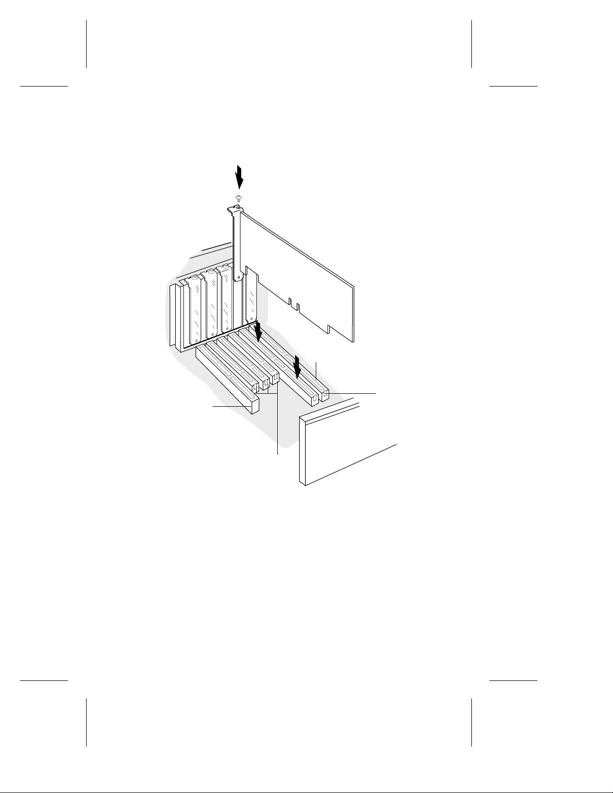
Insert the NIC into the expansion slot, pressing down firmly
8
until the bus contacts are seated in the slot.
3-4
Page 41
DuraLAN NIC Installation
9 Replace the screw that was removed in step 4, see the figure
below.
64-bit PCI Expansion
Slots
ISA Expansion
Notch
Slot
32-bit PCI
Expansion
Slots
Figure 3-1. Install the DuraLAN NIC in a 64-bit PCI expansion slot.
10 Replace the computer cover.
11 Continue with Connecting the Network Cable on page 3-6.
3-5
Page 42

DuraLAN Fast Ethernet NICs User’s Guide
Connecting the Network Cable
Cable requirements for Adaptec DuraLAN NICs vary according to
network speed, cabling standard, and the connector to be used. See
Appendix A, Cables and LEDs for detailed information on cabling.
Determine the appropriate cabling for your network.
1
Connect the cable to the NIC connector. (For multiport NICs,
2
connect a cable to each port.)
Connect the other end of the cable to your hub, switch, or
3
client.
Continue with Installing the Appropriate NIC Driver.
4
3-6
Page 43

DuraLAN NIC Installation
Installing the Appropriate NIC Driver
After installing the DuraLAN NIC, you must install the appropriate
DuraLAN NIC driver. You may install one of three drivers: the
DuraLAN Standard driver, Duralink64 Failover, or Duralink64 Port
Aggregation. Please note that you may install one type only.
The Adaptec Duralink64 diskettes provide the following drivers:
Disk 1 Disk 2
Windows NT 4.0 Standard
Driver
Windows NT 3.51 Standard
Driver
Windows 95 Standard Driver NetWare Failover
Windows 98 Standard Driver DOS Diagnostics
Windows NT 4.0 Failover Driver NetWare
Windows NT 3.51 Failover
Driver
Windows NT 4.0
Port Aggregation\Fast
EtherChannel Driver
Windows NT 3.51
Port Aggregation\ Fast
EtherChannel Driver
NetWare 4.x and 5.0
Standard Driver
Client32 for DOS
Driver
Port
Aggregation\Fast
EtherChannel Driver
3-7
Page 44

DuraLAN Fast Ethernet NICs User’s Guide
■ DuraLAN Standard driver
The Standard driver uses each DuraLAN port independently.
Note: Windows 95, Windows 98, and Novell Client32 do
not support Duralink64 Failover. Install the DuraLAN
Standard driver for these operating systems.
■ Duralink64 Failover driver
The Duralink64 Failover driver groups two ports in a failover
combination, one as the primary port and the other as the backup
port. The ports may be connected to a hub or switch. describes this
software.
■ Duralink64 Port Aggregation\Fast EtherChannel driver
The Duralink64 Port Aggregation driver groups up to twelve ports
together and must be used with a switch. Fast EtherChannel can be
grouped in groups of two or four. This grouping requires a swit ch that
supports Fast EtherChannel.
Always use the latest software version available for your DuraLAN
NIC. Drivers are updated regularly on Adaptec’s World Wide Web,
FTP, and BBS sites to provide enhanced performance and new
features. See Technical and Product Support on page iii.
❒
3-8
Page 45

▼▼▼▼
Network Configuration Examples
In This Chapter
4
Network Without Duralink64 Failover
Protection
Single Hub or Switch on an Ethernet Segment 4-3
Dual Hubs 4-4
Dual Hubs with an Ethernet Switch 4-5
Dual Hubs with Routers 4-6
Dual Hubs with a Four-Port NIC 4-7
This chapter describes the benefits of using Duralink64 Failover and
some typical network configurations. The primary and backup
Adaptec DuraLAN Fast Ethernet NICs or ports reside in the server.
Duralink64 Failover operates on these NICs to provide redundancy
on the server. The backup port does not operate until the primary
port fails.
4-2
4-1
Page 46

DuraLAN Fast Ethernet NICs User’s Guide
Network Without Duralink64 Failover Protection
This configuration uses one NIC connected to a hub or switch on an
Ethernet segment. If the NIC fails, all network traffic is stopped.
Ethernet Switch or
Ethernet Hub
Server
Clients
Figure 4-1. Network without Duralink64 Failover protection
4-2
Page 47
Network Configuration Examples
Single Hub or Switch on an Ethernet Segment
This configuration uses two NICs connected to a hub or switch on
an Ethernet segment. Duralink64 Failover provides failover
capability if one NIC fails.
Ethernet Switch or
Ethernet Hub
Clients
Figure 4-2. Single hub or switch on an Ethernet segment
Primary
Backup
Server
4-3
Page 48
DuraLAN Fast Ethernet NICs User’s Guide
Dual Hubs
In this example, each NIC is connected to a separate hub to provide
redundancy. If the hub port being used by the primary NIC fails, the
backup NIC becomes active and all network traffic is immediately
directed through it.
Clients
Ethernet Hub
Primary
Server
Ethernet Hub
Backup
4-4
Clients
Figure 4-3. Two NICs connected to separate hubs
Page 49

Network Configuration Examples
Dual Hubs with an Ethernet Switch
This example shows how Duralink64 Failover provides network
redundancy to a switched network. Ethernet switches provide
network traffic segmentation.
Clients
Ethernet Hub
Ethernet Switch
Ethernet Hub
Primary
Server
Backup
Clients
Figure 4-4. Duralink64 Failover on a network with
dual hubs and an Ethernet switch
4-5
Page 50

DuraLAN Fast Ethernet NICs User’s Guide
Dual Hubs with Routers
The following example shows how to set up Duralink64 Failover in
a network configuration using routers. Rout ers provide WAN and
LAN connectivity and allow physical network protocol redundancy .
Router
Uplink
Router
Figure 4-5. Duralink64 Failover in a network configuration using routers
Ethernet Hub
Ethernet Hub
Primary
Server
Backup
4-6
Page 51

Network Configuration Examples
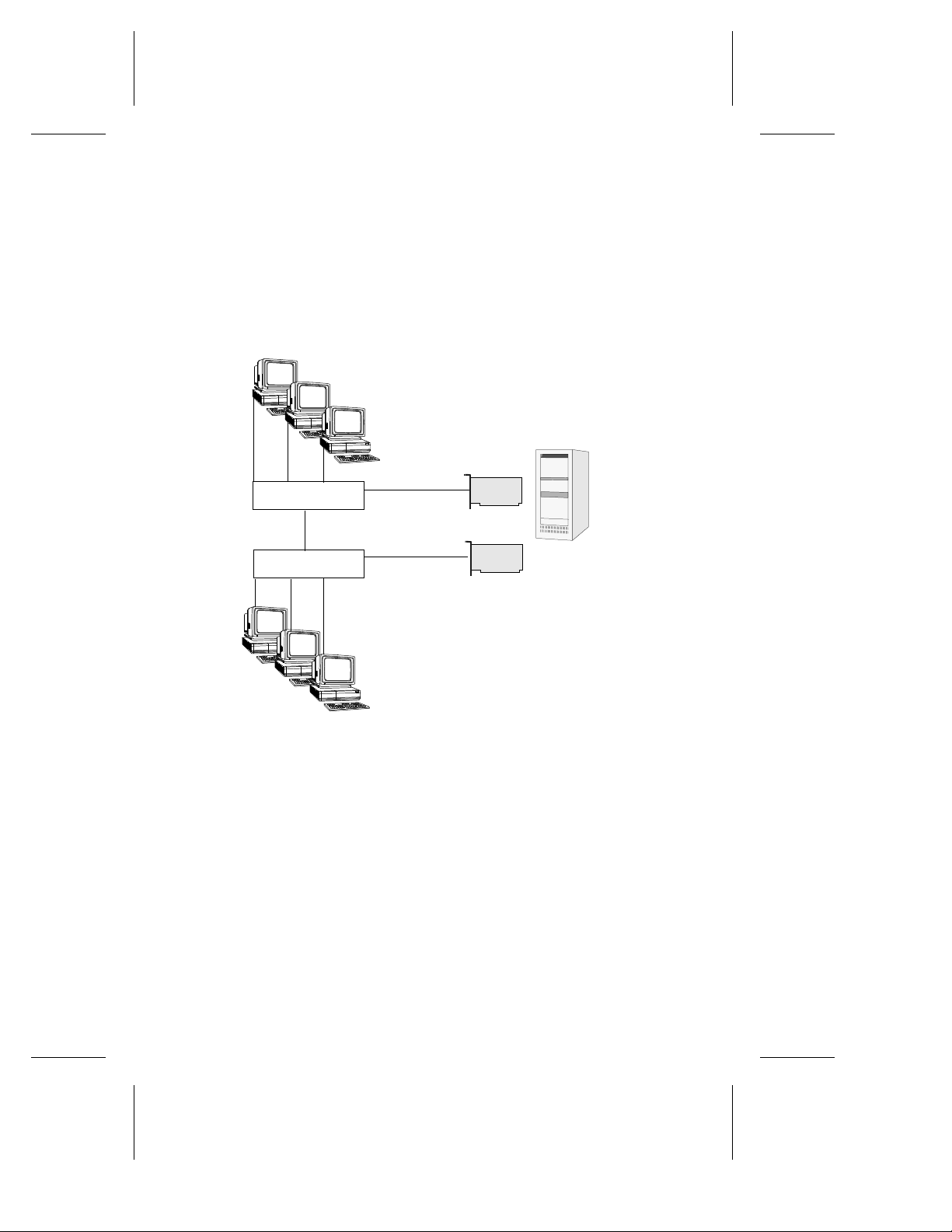
Dual Hubs with a Four-Port NIC
This example shows port redundancy, using Duralink64 Failover,
within a 4-port NIC. As shown in the illus tration below, Ports 1 and
3 are used as the primary ports to each Ethernet hub. Ports 2 and 4
are backup ports connected to each hub.
Clients
❒
Port1
Ethernet Hub
Ethernet Hub
Clients
Figure 4-6. A 4-Port NIC provides port redundancy
Port2
Port3
Port4
Primary
Backup
Server
4-7
Page 52

Page 53

▼ ▼ ▼ ▼
Part 3
The DuraLink64
Driver for Windows
Page 54

Page 55

5
▼▼▼▼
Duralink64 Driver Installation for Windows
In This Chapter
Before You Begin 5-2
Note on DuraLAN NIC Ports 5-2
Installing the DuraLAN Driver 5-3
Installation Tips 5-11
Removing Previously Installed Drivers 5-13
This chapter provides instructions for installing the DuraLink64 ®
driver of your choice on a server running Windows NT versions 4.0
and 3.51.
5-1
Page 56

DuraLAN Fast Ethernet NICs User’s Guide
Before You Begin
■ Verify that all system, memory, and NIC requirements are met, see
System Requirements on page 1-2.
■ Verify that the new Adaptec DuraLAN NIC is installed properly in
the server, see Chapter 3, DuraLAN NIC Installation.
■ Check your system for installed DuraLAN NIC drivers. If a
DuraLAN Standard driver, Duralink64 Failover driver, or Duralink64
Port Aggregation driver exists, remove it! See Removing Previously
Installed Drivers on page 5-13.
Caution: This procedure is critical. Only one DuraLAN
driver may exist in a system!
Note on DuraLAN NIC Ports
When you are installing Adaptec DuraLAN NICs, it is a good idea
to document where each port physically resides in the server,
especially when two or more identical NICs exist. This is important
because ports are identified by generic port names, such as Adptsf1,
Adptsf2, Adptsf3, etc.
Port names are assigned to ports in the order that the system scans
these ports at boot time. Consequently, whenever you physically
rearrange the network cards , the port names change as well.
5-2
Page 57

Duralink64 Driver Installation for Windows
Installing the DuraLAN Driver
Windows NT 4.0
If you are installing Windows NT at this time, start with step 6 when
prompted for the DuraLAN NIC.
T o install the DuraLAN driver on a W indo ws NT 4.0 platform follow
these steps:
Start Windows NT.
1
From the Start menu, point to Settings, and then click Control
2
Panel.
In the Control Panel, double-click Network.
3
In the Network window, click the Adapters tab.
4
In the Adapters tab, click Add.
5
In the Select Network Adapter window, click Have Disk.
6
Figure 5-1. Select Network Adapter
5-3
Page 58
DuraLAN Fast Ethernet NICs User’s Guide
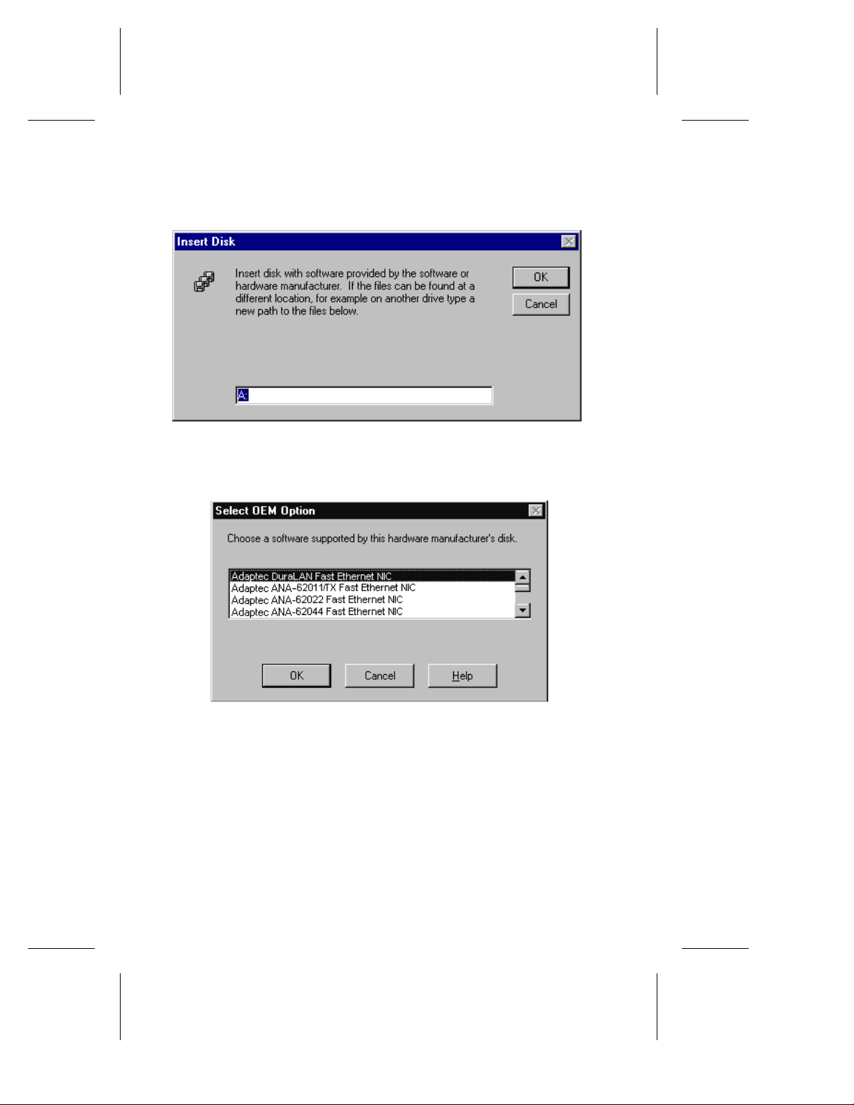
7 At the Insert Disk window, insert the Duralink64 for Windows
diskette, and then click OK.
Figure 5-2. Insert Disk Window
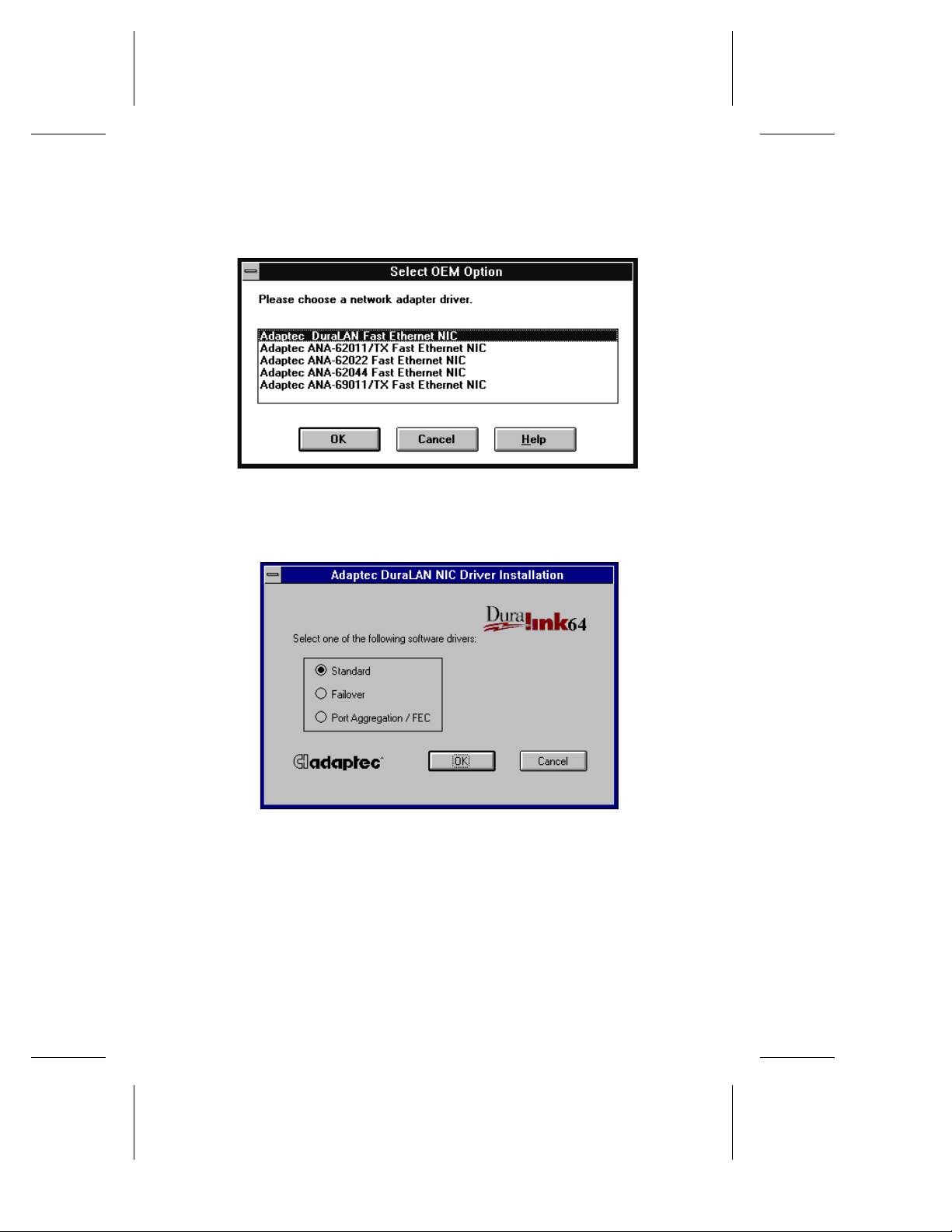
8 In the Select OEM Option window, click the DuraLAN NIC model
that is installed and then click OK.
5-4
Figure 5-3. Select OEM Option Window
Page 59

Duralink64 Driver Installation for Windows
9 In the Adaptec DuraLAN NIC Driver Installation window, select the
driver and then click OK.
Figure 5-4. Adaptec NIC Driver Installation Window
10 Continue to the appropriate configuration chapter:
– Chapter 6, Duralink64 Standard Dr iver f or Windows.
– Chapter 7, Dur alink64 Failover for Windows NT.
– Chapter 8, Duralink64 Port Aggregation for Windows NT.
5-5
Page 60

DuraLAN Fast Ethernet NICs User’s Guide
Windows NT 3.51
If you are installing Windows NT at this time, start with step 6 when
prompted for the DuraLAN NIC.
To install the DuraLAN driver on a Windows NT 3.51 platform,
follow these steps:
Start Windows NT.
1
From the Main Group menu click Control Panel.
2
In the Control Panel, double-click Network.
3
In the Network Settings window, click Add Adapters.
4
Figure 5-5. Network Settings Window
In the Add Network Adapter window, select (Other) Requires disk
5
from manufacturer.
Figure 5-6. Add Network Adapter
At the Insert Disk window, insert the Duralink64 for Windows
6
diskette and then click OK.
5-6
Page 61
Duralink64 Driver Installation for Windows
7 In the Select OEM Option window, click the DuraLAN NIC model
that is installed and then click OK.
Figure 5-7. Select OEM Option Window
8 In the Adaptec DuraLAN NIC Driver Installation window, select the
driver and then click OK.
Figure 5-8. Adaptec DuraLAN Driver Installati on
9 Continue to the appropriate configuration chapter:
– Chapter 6, Duralink64 Standard Dr iver f or Windows.
– Chapter 7, Dur alink64 Failover for Windows NT.
– Chapter 8, Duralink64 Port Aggregation for Windows NT.
5-7
Page 62

DuraLAN Fast Ethernet NICs User’s Guide
Windows 98
To install the DuraLAN Driver on the Windows 98 platform, follow
these steps:
Start Windows 98, and wait for the New Hardware window to open.
1
In the first screen, click Next.
2
In the next window, click Search for the best driver for your
3
device. (Recommended), and then click Next.
In the next window, select Floppy Disk Drives.
4
Insert the Duralink64 for Windows Disk, and then click Next.
5
Note:
If you do not insert the floppy disk, this message
appears: Windows was unable to locate a driver for this
device. If you do not want to install a driver now, click
Next. To search again, click Back.
The system indicates that the driver file was found. Insert the CD you
6
used to install Windows 98, and then click Next.
Note:
You may receive the following Version Conflict
message: A file being copied is older than the file currently
on your computer. It is recommended that you keep your
existing file. Do you want to keep the file? Click Yes.
1
Click Finish.
7
Remove the fl oppy disk.
8
If the System Settings Change window appears, click Yes to restart
9
the system.
Continue to Chapter 6, Duralink64 Standard Driver for Windows.
10
1
If the wizard does not open, refer to the Installation Tips on
5-8
page 5-12
.
Page 63

Duralink64 Driver Installation for Windows
Windows 95
This section provides instructions for installing the DuraLAN
Standard driver in Windows 95 OSR1 and OSR2. To verify which
version of Windows 95 is installed, see Important Note for W indows 95
Users! on page 3-2.
Windows 95 OSR2
To install the DuraLAN Standard driver on a Windows 95 OSR2
platform, follow these steps:
Start Windows 95. The Update Device Driver wizard opens.
1
Insert the Duralink64 for Windows diskette.
2
In the wizard, click Next.
3
Click Finish.
4
In the Insert Disk window, click OK.
5
Type a:\ and then click OK.
6
In the Insert Disk window, insert the Windows 95 CD, then click OK.
7
Enter the path to the Windows 95 installation directory, and then click
8
OK. (For example d:\win95.
documentation for help.)
1
Consult your Microsoft Windows 95
Remove the floppy disk from the floppy drive.
9
At the System Settings Change window, restart the system.
10
Optional. To verify the driver installation, see Installation Tips
11
starting on page 5-11.
Note:
As the system restarts, Windows 95 applies the
driver files to each additional port detected.
Continue to Chapter 6, Duralink64 Standard Driver for Windows.
12
1
In this example,
represents the CD-ROM drive letter.
d:\
5-9
Page 64

DuraLAN Fast Ethernet NICs User’s Guide
Windows 95 OSR1
To install the DuraLAN Standard Driver Windows 95 OSR1
platform, follow these steps:
Start Windows 95. The New Hardware Found wizard opens.
1
In the wizard, click Driver from disk provided by hardware
2
manufacturer, and then click OK.
Insert the Duralink64 for Windows Disk.
3
In the Install from Disk window, type a:\win95a and then click OK.
4
Caution:
will copy the wrong files which will cause errors in
!
Windows 95 OSR1 version.
In the Copying Files... window, insert the Windows 95 CD, and then
5
click OK.
Enter the path to the Windows 95 directory, and then click OK. (For
6
example, d:\win95.
documentation for help.)
Remove the floppy disk from the floppy disk drive.
7
If the System Setting Change window appears, click Yes to restart the
8
system.
Note:
driver files to each additional port detected.
Optional. To verif y the driver i nstallati on, see Install ation Tips starting
9
on page 5-11.
Continue to Chapter 6, Duralink64 Standard Driver for Windows.
10
If you accept the default path, a:\, the system
1
Consult your M icrosoft Windows 95
As the system restarts, Windows 95 applies the
1
In this example, d:\ represents the CD-ROM drive letter.
5-10
Page 65

Duralink64 Driver Installation for Windows
Installation Tips
This section provides tips to assist you in the DuraLAN driver
installation.
Windows 95
How do I verify that the DuraLAN Standard driver is installed
properly?
From the Start menu, point to Settings, then click Control Panel.
1
In the Control Panel, double-click System.
2
In the Device Manager tab, look under Network adapters.
3
Figure 5-9. The DuraLAN NIC appears under Network adapters
The DuraLAN NIC appears under Network Adapters. Click OK.
4
5-11
Page 66

DuraLAN Fast Ethernet NICs User’s Guide
A yellow exclamation ! appears bes ide the DuraLAN NIC. What
should I do?
Remove the current DuraLAN Standard driver and then reinstall it.
See Windows 98 and 95 OSR1/OSR2 on page 5-14.
In the Device Manager, the new NICs replace the older NICs, but the
Network window lists both. What should I do?
Remove the older NIC(s).
1 In the Network window, click the old NIC and then click Remove.
Repeat this step for each appropriate NIC.
2 Click OK when you are done.
Windows 98
How do I access the Add New Hardware wizard if it does not open?
1 Click the Start menu, point to Settings, and then click the Control
Panel.
2 In the Control Panel, double-click Add New Hardware.
Windows Clients Using Novell Client32
Connecting clients to the NetWare Duralink64 server requires the
NDIS driver. Do not use an ODI driver! See Installing Duralink64
NetWare Client on page 12-1.
5-12
Page 67

Duralink64 Driver Installation for Windows
Removing Previously Installed Drivers
This section provides instructions for removing the previously
installed DuraLAN Standard driver which is necessary if you are
installing the new Duralink64 driver included with your DuraLAN
NIC.
Windows NT 4.0
To remove the previously installed DuraLAN driver from a
Windows NT 4.0 platform, follow these steps:
Double-click My Computer .
1
Double-click Control Panel.
2
Double-click Network.
3
In the Network window, click the Adapters tab.
4
In the Network Adapters list, click the Adaptec DuraLAN NIC you
5
want to remove, and then click Remove.
When asked if yo u w ish to continue, click Yes.
6
Repeat step 5 until all Adaptec DuraLAN drivers are removed.
7
When you are done, click OK.
8
Click Close to close the Network window.
9
Click Yes to restart your computer.
10
Note:
When you restart Windows NT, a message may indicate
that at least one service failed to start. This message will not
appear after you add the new driver. Click OK.
5-13
Page 68

DuraLAN Fast Ethernet NICs User’s Guide
Windows NT 3.51
To remove the previously installed Duralink64 driver from the
Windows NT 3.51 platform, follow these steps:
In the Main window, double-click Control Panel.
1
In the Control Panel, double-click Network to enter the Net wor k
2
Settings window.
In the Installed Adapters Cards box, click the DuraLAN NIC, and
3
then click Remove.
Repeat step 3 until all DuraLAN NICs have been removed.
4
Click OK when you are done.
5
Restart the system.
6
Windows 98 and 95 OSR1/OSR2
To remove the previously installed DuraLAN driver from the
Windows 98 and Windows 95 OSR1/OSR2 platform, follow these
steps:
From the Start menu, point to Settings, and then click Control
1
Panel.
In the Control Panel, double-click System.
2
Select the Device Manager tab, then click Network Adapters.
3
Select Adaptec DuraLAN NIC to remove, then click Remove.
4
Repeat steps 3 and 4 for each existing DuraLAN NIC.
5
Restart the system.
6
❒
5-14
Page 69

▼▼▼▼
Duralink64 Standard Driver for Windows
In This Chapter
6
Configuring the Standard Driver Ports in
Windows NT 4.0 and 3.51
Configuring the Ports in Windows 98/95 6-4
This chapter describes how to configure the DuraLAN Standard
driver for Windows.
6-2
6-1
Page 70

DuraLAN Fast Ethernet NICs User’s Guide
Configuring the Standard Driver Ports in Windows NT 4.0 and 3.51
In the Adaptec New Hardware Found window, each port is
assigned to Autodetect, the default connection type that will always
detect port connection and negotiate a compatible speed and
transmission mode.
Note: If you are required to insert t he W ind ows NT CD, you mu st
re-install the latest version of the Microsoft Windows NT Service
Pack, and then restart the system.
In the Adaptec New Hardware Found window, make sure all the
1
DuraLAN NIC ports appear.
Figure 6-1. This window identifies each port’s PCI bus and PCI slot
In the New Adaptec NIC Port(s) Available for DuraLAN NIC box,
2
click the appropriate port.
In the Connection Types list, click the connection type for your
3
network or us e
see Connection Types on page A-2.
6-2
Autodetect Default Connection
. For descriptions,
Page 71

Duralink64 Standard Driver for Windows
4 Click Apply.
5 Repeat steps 1 through 4 for each existing port.
6 When you are done, click OK.
7 When you are done, click Close in the Network window.
8 Restart the system.
6-3
Page 72

DuraLAN Fast Ethernet NICs User’s Guide
Configuring the Ports in Windows 98/95
To configure ports in Window 98 and Windows 95 OSR2 or OSR1,
follow these steps:
From the Start menu, point to Settings, and then click Control
1
Panel.
In the Control Panel, double-click Network.
2
In the Network window, click the appropriate DuraLAN NIC, and
3
then click Properties.
Figure 6-2. Windows 95 Configuration Tab
In the Properties window, click the Advanced tab.
4
In the Property box, click Connection Type .
5
6-4
Page 73

Duralink64 Standard Driver for Windows
6 In the Value list, click the appropriate connection type. (Connection
Types on page A-2 provides descriptions.)
Figure 6-3. Advanced Tab
7 Click OK.
8 In the Configuration tab, click OK.
9 Restart your system.
❒
6-5
Page 74

Page 75

7
▼▼▼▼
Duralink64 Failover for Windows NT
In This Chapter
Configuring the Ports 7-2
Creating the Failover Pair 7-3
Monitoring Failover Pairs 7-8
Note on DuraLAN NIC Ports 7-8
This chapter provides instructions for installing Duralink64 Failover
on a server running Windows NT versions 4.0 and 3.51.
7-1
Page 76

DuraLAN Fast Ethernet NICs User’s Guide
Configuring the Ports
In the Adaptec New Hardware Found window, each port is
assigned to Autodetect, the default connection type that will always
detect port connection and negotiate a compatible speed and
transmission mode.
In the Adaptec New Hardware Found window, make sure all the
1
DuraLAN NIC ports appear.
Figure 7-1. This window identifies each port’s PCI bus and PCI slot
Note: Generally, PCI Bus 0 is the PCI Bus on the
motherboard. PCI Bus 1 or above is an ANA-62022 or
ANA-62044 NIC. The PCI Slot represents the port on the
NIC starting from the top. The top port starts at PCI Slot 4.
In the New Adaptec NIC Ports Available box, click the appropriate
2
port.
In the Connection Types list, click the connection type for your
3
network or us e
see Connection Types on page A-2.
Click
4
7-2
Apply
Autodetect Default Connection
.
. For descriptions,
Page 77

Duralink64 Failover for Windows NT
5 Repeat steps 1 through 4 for each existing port.
6 When you are done, click OK.
7 Continue with Creating the Failover Pair.
Creating the Failover Pair
You can create Failover pairs in the Conf iguration tab. A Failover
pair consists of two ports only—the primary port and the backup
port.
Windows NT 4.0
To create Failover pairs, follow these steps:
1 From the Available Adaptec Ports box, click a port to be designated
as a primary port.
Figure 7-2. Failover Configuration Tab
2 Click Add. The port is added under Primary Port in the Failover Pair
list.
3 To assign a backup to the primary port, click the appropriate port
from the Available Adaptec Ports box, and then click Add. The port
is added in the Backup Port field.
7-3
Page 78

DuraLAN Fast Ethernet NICs User’s Guide
4 Click Apply.
PTIONAL
5 O
6 O
PTIONAL
. Repeat steps 1 through 5 to create another Failover pair.
. To remove a Failover pair:
a Click the port from the Primary Ports list, and then click Remove.
Both ports return to the Available Adaptec Ports box.
b Click Apply.
7 When you are done, click OK. you will return to the Adapters tab.
7-4
Figure 7-3. <Backup NIC1> indicates that Port 2
is the backup port for Port 1
Note:
The Adapters tab identifies one model only, even
when several DuraLAN NIC models are installed. The
DuraLAN NIC model displayed is the same as the first
model you chose in step 8 during the driver installation.
Page 79

Duralink64 Failover for Windows NT
8 If SNMP is not set up, you will receive the Setup Message below.
Click OK.
Figure 7-4. This message may be ignored during this installation.
9 Enter the protocol in formati on. Con sult you r Microsof t Windows NT
4.0 documentation for help configuring the protocol.
10 When you are done, remove the floppy disk from the floppy drive.
11 Restart the system.
Note:
If you were required to insert the Windows NT CD, you
must re-install the latest version of Microsoft Windows NT
Service Pack, and then restart the system.
7-5
Page 80

DuraLAN Fast Ethernet NICs User’s Guide
Windows NT 3.51
To create Failover pairs, follow these steps:
From the Available Adaptec Ports box, click the port you want as the
1
primary port.
Figure 7-5. Configuration Tab
Click Add. The port is added under Primary Port in the Failover Pair
2
list.
To assign a backup to the primary port, click the appropriate port
3
from the Available Adaptec Ports box, and then click Add. The port
is added in the Backup Port field.
Click Apply.
4
PTIONAL
7-6
5
6
O
PTIONAL
O
Click the port from the Primary Ports list, and then click Remove.
a
Both ports return to the Available Adaptec Ports box.
Click Apply.
b
. Repeat steps 1 through 5 to create another Failover pair.
. To remove a Failover pair
Page 81

Duralink64 Failover for Windows NT
7 When you are done, click OK. you will return to the Network
Settings Window.
Figure 7-6. Network Setting Window
8 Click OK.
Note:
The Adapters tab identifies one model only, even
when several DuraLAN NIC models are installed. The
DuraLAN NIC model displayed is the same as the first
model you chose in step 8 during the driver installation.
9 If SNMP is not set up, you will receive the Setup Message below.
Click OK.
Figure 7-7. This message may be ignored during this installation.
7-7
Page 82

DuraLAN Fast Ethernet NICs User’s Guide
10 Consult your Microsoft Windows NT 3.51 documentation fo r help
configuring the protocol (such as entering values for TCP/IP).
11 When you are done, remove the floppy disk from the floppy disk
drive.
12 In the Network Setting Change window, click Restart Now.
Note:
If you were required to insert the Windows NT CD, you
must re-install the latest Microsoft Windows NT Service Pack,
and then restart the system again.
Monitoring Failover Pairs
There are three ways to monitor the status of the Failover Pairs:
■ SNMP Manager—when failover occurs SNMP traps are sent to
network management stations and error logs are updated through the
operating system event log. In order to manage SNMP agents,
compile the following MIB file on the SNMP management station:
a:\snmpmibs\duralink.mi b
■ Event Viewer Dialog Box—the local Event Viewer dialog box will
log port failures in Windows NT.
■ Duralink64 Failover window —the Status tab monitors the traffic and
health of the failover pairs.
Note on DuraLAN NIC Ports
When you are installing Adaptec DuraLAN NICs, it’s a good idea to
document where each port physically resides in the server,
especially when two or more identical NICs exist. This is important
because ports are identified by generic port names, such as Adptsf1,
Adptsf2, Adptsf3, etc.
Port names are assigned to ports in the order that the system scans
these ports at boot time. Consequently, whenever you physically
rearrange the network cards , the port names change as well.
❒
7-8
Page 83

8
▼▼▼▼
Duralink64 Port Aggregation for Windows NT
In This Chapter
Configuring the Ports 8-2
Creating Port Aggregation Groups 8-4
Creating Fast EtherChannel Groups 8-8
Assigning the TCP/IP Address 8-11
Modifying Groups 8-13
Checking System Status 8-17
Windows NT Performance Monitor 8-20
This chapter provides instructions for configuring Duralink64 Port
Aggregation on a server running Windows NT.
8-1
Page 84

DuraLAN Fast Ethernet NICs User’s Guide
Configuring the Ports
In the Adaptec New Hardware Found window, each port is
assigned to Autodetect, the default connection type that will always
detect port connection and negotiate a compatible speed and
transmission mode.
In the Adaptec New Hardware Found window, make sure all
1
the DuraLAN NIC ports appear.
Figure 8-1. This window identifies each port’s PCI bus and PCI slot
Note: Generally, PCI Bus 0 is the PCI Bus on the
motherboard. PCI Bus 1 or above is an ANA-62022 or
ANA-62044 NIC. The PCI Slot represents the port on
the NIC starting from the top. The top port starts at
PCI Slot 4.
In the New Ava ilable NIC Ports Availa ble box, click the
2
appropriate port.
8-2
Page 85

Duralink64 Port Aggregation for Windows NT
3 In the Connection Types list, click the connection type for your
network or use Autodetect Default Connection. For
descriptions, see Connection Types on page A-2.
4 Click Apply.
5 Repeat steps 1 through 4 for each existing port.
6 When you are done, click OK.
7 Continue to Creating Port Aggregation Groups.
8-3
Page 86

DuraLAN Fast Ethernet NICs User’s Guide
Creating Port Aggregation Groups
This section explains how to assign ports to a group, thus, creating a
virtual port. If you have installed Duralink6 4 Port Aggregation
already and wish to add or modify existing group or stand-alone
port configurations, see Modifying Groups on page 8-13.
In the Group(s) field, click Create New Group, and then type
1
the new group name.
Note: The group name may be up to 20 characters. If you skip
this step, the system assigns a default group name (GroupX).
Figure 8-2. Duralink64 Port Aggregati on Configuration Tab
In the Link Aggregation Type field, click the appropriate link
2
type. For a description of Adaptec’s Port Aggregation, see
Chapter 2, Introduction to Duralink64 Port Aggregation.
Note on Cisco’s Fast Ether Channe l. This option allows you
to fully aggregate two or four ports over transmit and
receive under all protocols. The ports that are configured as
the Fast EtherChannel group must be physically connected
to the Fast EtherChannel ports on the Cisco switch. See your
8-4
Page 87

Duralink64 Port Aggregation for Windows NT
Cisco switch documentation to configure the ports in Fast
EtherChannel mode.
If you select Fast EtherChannel on the server, th e connection
type for each port is automatically configured to 100 Mbps
TX/Full Duplex. You must also configure the ports on the
Cisco switch (used by the Fast EtherChannel group) to
either Auto Negotiation or 100 Mbps/Full Duplex mode.
Figure 8-3. The Link Aggregation Type Options
8-5
Page 88

DuraLAN Fast Ethernet NICs User’s Guide
3 In the Available Adaptec Ports box, click the available port to
add to the group, and then click Add.
4 Repeat step 3 for each additional port.
Note: You must assign the same connection type to
each port in the same group.
O
PTIONAL
appropriate port from the Group Ports box, and then click
Remove.
. To remove a port from the grou p, click the
5 When you are finished configuring the group, click Apply.
6 To create another group, repeat steps 1 through 5.
7 If you want to rename a group:
a Select the default group name in the Group(s) list box.
b Type the new name.
c Click Apply.
8 When you are finished configuring all groups, click OK.
9 If SNMP is not set up on the computer, you will receive the
message below. Click OK.
Figure 8-4. This message may be ignored during this
installation.
8-6
Page 89

Duralink64 Port Aggregation for Windows NT
10 In the Network window, click Close.
Figure 8-5. Ports and Groups Listed in Adapters Tab
11 Continue to Assigning the TCP/IP Address on page 8-11.
8-7
Page 90

DuraLAN Fast Ethernet NICs User’s Guide
Creating Fast EtherChannel Groups
Fast EtherChannel (FEC) allows you to fully aggregate two or four
ports over transmit and receive under all protocols. The ports that
are configured as the FEC group must be physically connected to the
FEC ports on the Cisco switch. See your Cisco switch documentation
to configure the ports in FEC mode.
If you select Fast EtherChannel on the server, the connection type for
each port is automatically configured to 100 Mbps TX/Full Duplex.
You must also configure the ports on the Cisco switch (used by the
FEC group) to either Auto Negotiation or 100 Mbps/Full Duplex
mode
This section explains how to assign ports to a Fast EtherChannel
group, thus, creating a virtual port. If you have installed Duralink64
Port Aggregation/FEC already and wish to add or modify existing
group or stand-alone port configurations, see Modifying Groups on
page 8-13.
In the Group(s) field, click Create New Group, and then type
1
the new group name.
8-8
Figure 8-6. Duralink64 Port Aggregati on Configuration Tab
Page 91

Duralink64 Port Aggregation for Windows NT
Note: The group name may be up to 20 char ac ters. If
you skip this step, the system assigns a default group
name (GroupX).
2 In the Link Aggregation Type field, click the appropriate link
type. For a description of Adaptec’s Port Aggregation, see
Chapter 2, Introduction to Duralink64 Port Aggregation.
3 In the Available Adaptec Ports box, click the available port to
add to the group, and then click Add.
4 Repeat step 3 for each additional port.
Note: You must assign the same connection type to
each port in the same group.
O
PTIONAL
appropriate port from the Group Ports box, then click Remove.
. To remove a port from the grou p, click the
5 When you are finished configuring the group, click Apply.
6 To create another group, repeat steps 1 through 5.
7 If you want to rename a group:
a Select the default group name in the Group(s) list box.
b Type the new name.
c Click Apply.
8 When you are finished configuring all groups, click OK.
9 If SNMP is not set up, you will receive the Setup Message
below. Click OK
Figure 8-7. This mes sage may be ignored during this installati on
.
8-9
Page 92

DuraLAN Fast Ethernet NICs User’s Guide
10 In the Network window, click Close.
Figure 8-8. Ports and Groups Listed in Adapters Tab.
11 Continue to Assigning the TCP/IP Address on page 8-11.
8-10
Page 93

Duralink64 Port Aggregation for Windows NT
Assigning the TCP/IP Address
Note: If you are an Windows NT 3.51 user, please refer to the
Windows NT 3.51 documentation for help configuring protocols.
Once you have configured Duralink64 Port Aggregat ion, Windows
NT prompts you to configure the protocol. IP addresses to groups
and stand-alone ports are assigned in the IP Address tab, such as
shown in the following figure. Ports assigned to a group use the
same IP address; therefore, it must be entered only once.
To assign a TCP/IP Address follow these steps.
Figure 8-9. IP Address Tab
In the IP Address tab, click the DuraLAN NIC port from the
1
Adapter list.
In the IP Address field, type the IP address.
2
8-11
Page 94

DuraLAN Fast Ethernet NICs User’s Guide
3 In the Subnet Mask field, type the subnet mask number.
4 Click Apply.
5 Repeat steps 1 through 4 for any other port or group.
6 Click OK when you are finished configuring all groups.
7 Restart your computer to complete the changes.
8 Click Yes at the message prompt to restart your computer.
9 Continue to Checking System Status on page 8-17.
Once Duralink64 Port Aggregation is installed, you may update
group and port configurations using the instructions in the
Modifying Groups section.
8-12
Page 95

Duralink64 Port Aggregation for Windows NT
Modifying Groups
This section provides instructions for modifying the group or port
configurations. You may rename groups, as well as add or remove
ports from existing groups.
Renaming Groups
In the Duralink64 Port Aggregation window, go to the
1
Configuration tab.
Figure 8-10. Modified groups in the Configuration tab
From the Gro up(s) field, select the appr opriate gr oup, and then
2
type the new name.
Click Apply.
3
8-13
Page 96
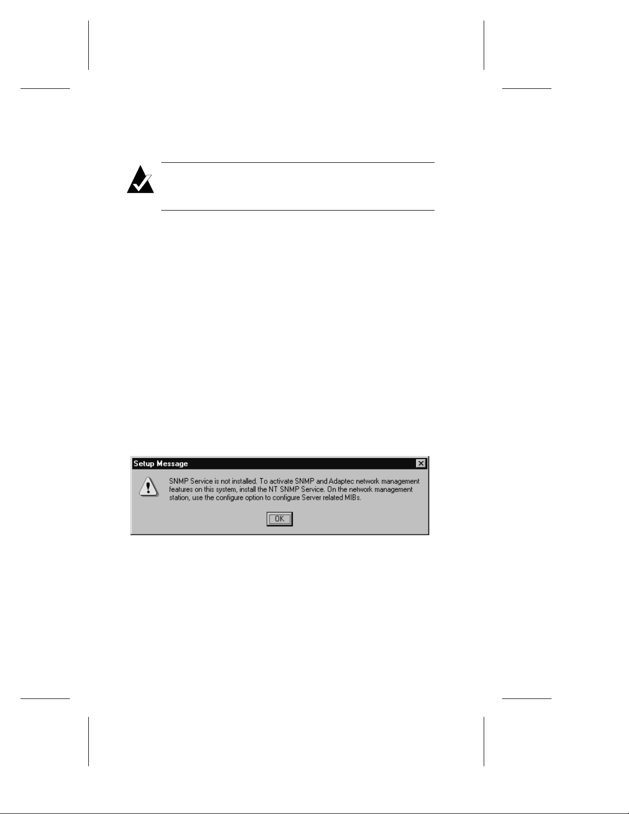
DuraLAN Fast Ethernet NICs User’s Guide
Adding or Removing Ports
Note: If you add or remov e a port to o r from a group, any existi ng
group or port IP address is removed automatically. Keep track of
any IP addresses you plan to use again.
In the Duralink64 Port Aggregation window, go to the
1
Configuration tab.
In the Group(s) field, click Create New Group, and then type
2
the new group name, or select the appropriate group you want
to modify.
– To add ports to the group, click the appropriate port from the
Available Adaptec Ports box, and then click
– To remove ports from the group, click the appropriate port from
the Group Ports box, and then click
Repeat step 2 for each appropriate port.
3
To save changes, click Apply.
4
When you are finished, click OK.
5
Remove
Add
.
.
If SNMP is not set up on the computer, you will receive the
6
message below. Click OK.
Figure 8-11. This message may be ignored during this installation.
8-14
Page 97

Duralink64 Port Aggregation for Windows NT
7 When adding or deleting a group or port, you will receive a
message such as shown below. Click OK.
Figure 8-12. This message appears when you add ports with IP Addresses
Figure 8-13. This message appears when you add ports with IP Addresses
to Group2 with an existing IP Address.
to a new group.
8-15
Page 98

DuraLAN Fast Ethernet NICs User’s Guide
8 In the Network window, click Close.
8-16
Figure 8-14. Ports and Groups Listed in Adapters Tab
Page 99

Duralink64 Port Aggregation for Windows NT
Checking System Status
You can view group and independent port status. See Field
Descriptions on page 8-18 for details.
From the Start menu, point to Settings, and then click Control
1
Panel.
In the Control Panel, double-click Network.
2
In the Network window, click the Adapters tab.
3
In the Adapters tab, select the Adaptec DuraLAN NIC. The
4
Duralink64 Port Aggregation window appears.
Click Properties.
5
Click the Status tab to view the group and independent port
6
information, such as shown in below.
Click OK to exit.
7
Figure 8-15. Status Tab
8-17
Page 100

DuraLAN Fast Ethernet NICs User’s Guide
Understanding the Status Tab
Field Descriptions
Model
a
Port No.
b
Trans Kbps
c
Load
d
Status
e
a
Figure 8-16. Status Tab Fields
Adaptec DuraLAN NIC model number.
Port identification assigned by the system.
T otal Kilobits per second (Kbps) transmitted per port
(stand-alone and group). The Kbps sum of
aggregated ports in a group equals the total Kbps
transmitted by their group.
The percentag e of transmit load carried by each po rt
in a group. The percentage of a stand-alone port is
always 100%. The percentage for a group is
calculated as a percentage of bytes tr ansmitted by
the port over bytes transmitted by the g roup d u ring
the last screen refresh interval.
If the link is up and has transmitted data with in the
last screen refresh interval, ACTIVE is displayed.
If the link is up but the port has not transmitted any
data within the time interval, IDLE is displayed.
If the link is down, DOWN is displayed.
b
c
d
e
h
f
g
8-18
 Loading...