


▼ ▼ ▼ ▼
ANA-5910/5930/5940
PCI-to-ATM Adapter
User’s Guide
R
Copyright
© 1997 Adaptec Inc. All rights reserved. The user may
print one copy for personal use. Production of multiple
copies, or copies for sale is strictly prohibited
.

Trademarks
Adaptec, the Adaptec logo, and ANA are trademarks of Adaptec, Inc. which may be
registered in some jurisdictions.
Windows NT is a trad e mark, and Windows and Windows 95 are registered
trademarks of Microsoft Corporation in the U.S. and other countries used under
license.
All other trademarks are owned by their respective owners.
Changes
The material in t his document is for information only and is subject to change
without notice. While reasonable efforts have been made in the preparation of this
document to assure its accuracy, Adaptec, Inc. assumes no liability resulting from
errors or omissions in this document, or from the use of the information contained
herein.
Adaptec reserves th e right to mak e changes in the pro duct design with out reser vation
and without notification to its users.
Disclaimer
IF THIS PRODUCT DIRECTS YOU TO COPY MATERIALS, YOU MUST HAVE
PERMISSION FROM THE COPYRIGHT OWNER OF THE MATERIALS TO AVOID
VIOLATING THE LAW WHICH COULD RESULT IN DAMAGES OR OTHER
REMEDIES.
Adaptec Technical Support and Servic e s
If you have questions about installing or using your Adaptec product, check this
document first—you will find answers to most of your questions here. If you need
further assistance, please contact us. We offer the following support and information
services:
Electronic Support
Technical inf o rmation, including product literature, answers to commonly asked
questions, information on software upgrades and other topics is available
electronic ally through the following:
Adaptec World Wide Web (WWW) site at http://www.adaptec.com.
■
File Transfer Protocol (FTP) server at ftp.adaptec.com
■
Adaptec USA Bulletin Bo ard Service (BBS) at 408-945-7727; sup p orts up to 28,800
■
bps (bits per second), 8 data bits, 1 stop bit, no parity. No produc t literature is
available on the Adaptec BBS.
Interactive Fax System at 408-957-7150; available 24 hours a day, 7 days a week.
■
T echnical and Product Support
For technical support and information about many of Adaptec’s electronic
■
support services, c all 800-959- 7274 or 408 -945-2550, 24 hours a d ay, 7 days a week.
To use the Adaptec I nteractive Support System, call 800-959-7274 or
■
408-945- 2550, 24 hours a da y, 7 days a week. The system prompts you with
questions regarding your problem and then provides step-by-step
troubleshooting in structions.
.
ii

To speak with a product sup p ort representative, call 408 -9 34-7274, M–F, 6:00 A.M.
■
to 5:00
., Pacific Time. After hours, on weekends, and on holidays, product
P.M
support is also available for a fee at 800-416-8066.
Sales and Ordering Information
For sales information, call 800-959-7274 or 408-945-2550, M–F, 6:00A.M. to 5:00
■
., Pacific Time.
P.M
To order Adaptec s oftware and SCSI cables, call 800- 442-7274 o r 408-957-727 4, M–
■
F, 6:00
To reques t additional docum e ntation for Adapte c p roducts, call 800-934-2766 o r
■
510-732-3829, M– F, 6:00
. to 5:00 P.M., Pacific Time.
A.M
A.M
. to 5:00 P.M., Pacific Time.
Federal Communications Commission Radio Frequency Interference Statement
WARNING: Changes or modifications to this unit not expressly approved by the party responsible for compliance could void the user’s authority to operate the equipment.
This equipment has been tested and found to comply with the limits for a Class B digital device,
pursuant to Part 15 of the FCC rules. These limits are designed to provide reasonable protection
against harmful interference in a residential installation. This equipment generates, uses, and can
radiate radio frequency energy, and if not installed and used in accordance with the instruction
manual, may cause harmful interference to radio communications. However, there is no guarantee that interference will not occur in a particular installation. However, if this equipment does
cause interference to radio or telev ision equipment re ception, which can be determined by turni ng
the equipment off and on, the user is encouraged to try to correct the interfere nce by one or more
of the following measures:
• Reorient or relocate the receivi ng antenna.
• Increase the separation between equipment and recei ver.
• Connect the equipment to an ou tl et on a circuit different fr om that to which the receiver is connected.
• Consult the dealer or an experienced radio/television technician for help.
Use a shielded and properly grounded I/O cable and power cable to ensure compliance of this
unit to the specified limits of the rules.
This device complies with part 15 of the FCC rules. Operation is subject to the following two conditions: (1) this device may not cause harmful interference and (2) this device must accept any
interference received, including interference that may cause undesired operation.
Canadian Compliance Statement
This Class B digital apparatus meets all requirements of the Canadian Interfer ence-Causing
Equipme n t Reg u la ti o n s.
Cet appareil numérique de la classe B respecte toutes les exigences du Règlement sur le matérial
brouilleur du Canada.
iii


▼ ▼ ▼ ▼
1 Gett ing Started
System Requirements 1-1
Hardware Require ments 1-1
Document Overview 1 -3
How to Use This Document 1-3
2 Introducing ATM Networking
How ATM Wo rks 2-1
Wide Area Connectivity 2-2
Scaleable bandwidth 2-3
Bandwidth guarantees 2-3
Node I de ntificatio n 2-3
Virtual Channe l Con nections (VCCs) 2-4
ATM SONET/SDH Support 2-4
25.6 Mbit/sec ATM 2-5
Classical TCP/ I P 2- 5
Classical IP Operati onal Summary 2-6
Classical IP over ATM 2-7
LAN Emula ti on 2 -8
LAN Emulati on Cl ients (L EC s) 2-8
LAN Emulation Configuration Server (LECS) 2-9
LAN Emula ti on Se rv er (L ES ) 2-9
Broadcast and Unk nown S er v e r (BUS) 2-9
Contents
3 Installing the Adapter
Connecting the ANA-5910/5930/5940 Adapter to the
Network 3-4
Connecting to the ANA-5910 3-4
Connecting to the ANA-5930 3-5
v

ANA-5910/5930/5940 User’s Guide
Connecting to the AN A-5940 3-5
4 Installing ATM Version 4.0x Software for
Windows NT
Install ation for Windows NT (version 4.0) 4-1
Installing LANE Device Drivers 4-2
Installing The ATM Utilities 4-7
Install ation for Windows NT (version 3.51) 4-8
Installing LANE Device Drivers 4-8
Installing The ATM Utilities 4-13
Using Device Drivers and Utilities 4-14
Stopping ATM Drivers 4-14
Starting ATM Drivers 4-14
Locating Files and Director ies 4 -19
5 Insta lli ng A TM Ver si on 2 .0x D ri vers f or Wi n dows
NT
Install ation for Windows NT (version 4.0) 5-1
Installing CIP Client Drivers 5-2
Installing LANE Device Drivers 5-5
Installing the CIP ARP Server (Optional) 5-9
Install ation for Windows NT (version 3.51) 5-13
Installing CIP Client Drivers 5-13
Installing LANE Device Drivers 5-17
Installing the CIP ARP Server (Optional) 5-21
Using Device Drivers and Utilities 5-25
Stopping ATM Drivers 5-25
Starting ATM Drivers 5-25
Locating Files and Director ies 5 -30
6 Installing ATM Software for DOS/Windows 3.1
Configuring the Novell Net Ware Cli e nt Kit for DOS/
Windows 6 -1
Installing Adaptec ATM Software for DOS/Windows 6-2
vi

Using Frame Types with Novell NetWare 6-4
7 Installing ATM Software for Windows 95
Automatically Installing Adaptec ATM Software for
Windows 95 7- 1
Installing Adaptec ATM Client Drivers for Windows 95 7-3
Configuring the Adapter 7 -4
Removing Adaptec ATM Softwar e for Windows 95 7-5
8 Installing ATM Software for Novell NetWare
Installing Adaptec ATM Software for NetWare 3.12 8-1
Installing the ATM Software 8-1
Configuring the ATM Softwar e 8-3
Automatically Loading the ATM Driver 8-6
Automating ATM Software Installation 8-7
Installing, Configuring, and Loading Adaptec ATM
Software for NetWare 4.1 8-7
Installing and Configuring the ATM Software While
Installing NetWare 4.1 8-7
Installing and Configuring the ATM Software After
Installing NetWare 4.1 8-10
Automatically Loading the ATM Driver 8-14
Manually Loading the ATM Driver 8-14
Removing ATM Software 8-15
Removing ATM Software for NetWare 3.12 8-15
Removing ATM Software for NetWare 4.1 8-16
Updating ATM Softwa r e 8-1 7
Updating ATM Software for NetWare 3.12 8-17
Updating ATM Softwa r e for NetWa re 4.1 8-17
Troubleshooting 8-18
Status Commands 8-18
Status/Error Mes sages 8-18
Identifying Files 8-19
Installing Patches 8-19
Contents
vii

ANA-5910/5930/5940 User’s Guide
A Product Features and Specifications
Features A-1
ANA-5910/5930/5940 Hardware A-1
ANA-5910/5930/5940 Software A-3
Features Summary A-4
Specifications A-5
Environmen t A-5
PCI Interface A-5
UTP and STP Interface (ANA-5910/5930) A-6
MMF Optical Interface (ANA-5940) A-7
B Windows NT Specific Error Messages and
Diagnostics
Error Mes sa ge s B-1
Diagnostics Error Messages B-3
Driver Console Error Messages B-4
Diagnostics B-11
Database File Parameters B-14
SNMP Agent B-16
viii
Glossary
Index

▼▼▼▼
Getting Started
1
This document contains information on installing and configuring
the Adaptec
provide the interface between your computer’s PCI bus and a
network that uses Asynchronous T ransfer Mode (ATM). Pr oc edures
in this document describe installing the adapter, installing and
configuring the adapter drivers, and perform ing administrat ive and
management functions for your ATM network.
®
ANA™-5910/5930/5940 adapter s. These adapters
Note:
The procedures in this document assume that you are
connecting the adapter to an external ATM local area
network ( LAN) switch.
System Requirements
Certain hardware and software components are required to use the
ANA-5910/5930/5940 adap ters.
Hardware Requirements
The minimum hardware system requirements are as follows:
■
PCI rev. 2.0-compliant computer with +5V PCI slots f or the
ANA-5910 and +5V/+12V PCI slots for th e ANA-5930/5940
■
An available PCI b u s master slot
1-1

ANA-5910/5930/5940 User’s Guide
■
Connecting cable (see Appendix A, Product Features and
Specifications, for additional cable spec i f i cations):
Adapter Model Cable
ANA-5910 STP, UTP 3, or better
ANA-5930 UTP 5
ANA-5940 MMF
Adaptec does not claim to have included in this document every
condition or situation that might require a caution or warning
notice. Be sure to consult the documentation for your computer and
any connected equipment when you are installing the equipment or
changing its config uration.
WARNING:
equipment!
Always use caution when handling electrical
1-2

Getting St a rted
Document Overview
How to U se This Document
To use this do cument, firs t sca n this chapter for a n o verview o f th is
document .
Next read Chapt e r 2, Introducing ATM Networking, for a description
of ATM and how the ANA-5910/5930/5940 adapters fit into an
ATM network.
Then follow the instructio ns in Chapt er 3, Installing the Adapter, for
installing the adapter and connecting ATM UTP/STP or MMF.
After you install the hardware, install and configure the ATM
software for the operating system you are running, as follows:
Chapter 4, Installing ATM Version 4.0x Software for Windows NT.
Chapter 5, Installing ATM Version 2.0x Drivers for Windows NT.
Chapter 6, Installing A TM So ft ware for DOS/Windows 3.1.
Chapter 7, Installing ATM Soft ware for Windows 95.
Chapter 8, Installing ATM Soft ware for Novell Net Ware
For specifications on environment, cables, or the PCI-bus interface,
see Appendix A, Product Features and Specifications.
For error messages and diagnostics sp e ci f ic to W indows NT, refer to
Appendix B, Windows NT Specif ic Error Messag es and Diag nos tics
If you do not understand some of t he terms discussed in this
document, refer to the Glossary.
❒
1-3


2
▼▼▼▼
Introducing ATM
Networking
As a technology, ATM represents a sharp departure from LAN
alternatives such as traditional Ethernets that typically rely on
shared transmission me di a. That is, with Ethernet, severa l nodes
often contend for the right to transmit over shared cable segments
that support only one transmission at a time. When a node
successfully captures the media, it transmits its message at the
maximum allowed spee d, complet e ly consuming the media.
However, even in the best of circumstances, it is not unusual for two
or more nodes to begin transmitting at the same time and interfere
with each othe rs transmiss ion. Ethernet’s design anticipates and
compensates for unpredictable trans miss ion co llision s that occur.
How ATM Works
In cont rast to ot he r method s, ATM isolates netwo rk no des by fo rc i ng
them to attach to ATM switches using dedicated connections. ATM
switches the n intercon nect and cooperate with e a ch other to form a
network and p rovide commun ication conne ctions. While an ATM
node has full use of its switch attachment link, nodes share the
capacity of the links connecting the swi t ches. Unlike Ethernet
networks, this sharing is largely in visible to the nodes. Because of
this and other considerations, A TM provides numerous advantages
and capabilities that are difficult or impossible to obtain with legacy
LAN approaches. Perhaps the most important ATM benefits are its
2-1

ANA-5910/5930/5940 User’s Guide
native wide area connectivity, scaleable bandwidth, and bandwidth
guarantees.
Figure 2-1. ATM Networking
Wide Ar ea C o nnectivity
International telephon e companies have standardized ATM to
support their domestic telephone voice traffic. As nations deploy
their i ndividual ATM networks, ATM’s standard de f inition makes it
easy to in te rconnect th e se various ATM networks into a coop e rative
integrated global network.
2-2

Introducing ATM Networking
Scaleable bandwidth
ATM defines how ATM end-stations, such as your PC or
workstation, connec t to ATM switches and how ATM switches
interconnect with each other. Because these various co nne ctions
consist of dedicate d links, their construction (metal wire or fiber
optic) and the transmission speed they support may vary from link
to link. When connections require higher speed, it is usually easy to
upgrade the connection without disrupting other network nodes
and switches, upgrading transmission bandwidth only where
necessary.
Bandwidth guarantees
Whenever one ATM node communicates with another, it uses a
virtual connection that disguises the fact that connections actually
traverse shared media. In this way, ATM networks make it appear
that conne ctions are dedicated. Only if the necessary bandwidth is
available along the entire r oute does the connection setup complete
successfully. AT M’ s guarant eed bandw id th allo ws conne c tions to
transport audio, video, an d i mag e data that is sensit ive to time
delays that occur when bandwidth is unpredictable as it is with
Ethernet.
To further improve transmission predictability, ATM networks
transmit small, 53 byte messages, called cells. A cell contains 48 data
bytes and a five-byte head er. Since ATM tr ansmission media only
transport only one cell at a time, the small message size allows
switches and nodes to transmit high priority cells with minimum
delay. If switches are transmitting lower priority cells when a high
priority cell arrives, higher priorit y cell transm ission quic kly
commences when the lower priority transmission completes.
Node Identification
ATM end stations (nodes such as workstations) each have a unique
connection to any ATM switch to whic h they connec t. The
connection point at the switch is called a switch port and the switch
is a local sw itc h for the node. A T M nodes each have a globally-unique
network address. Ther e are various address schemes but, in most
cases, n odes r eceiv e their assigne d networ k addre ss fr om the switch .
2-3

ANA-5910/5930/5940 User’s Guide
To communicate with anot her node , an initiat ing node must initiat e
a signaling r eq uest to the signali ng Virtual Channel Connection (VCC)
residing within the local switch.
Virtual Channel Connections (VCCs)
Virtual Channel Connections (VCCs) are either constr ucted manual l y
or constructed by both nodes and all interv e ning switches.
Manually constructed connec tions are called Permanent V irtual
Circuits (PVCs) and must be manually deconstructed. With Switched
Virtual Connections (SVCs), one node ini tiates the VCC s e tu p p rocess
which proceeds switch-by-switch until the desired node is reached.
ATM networks that provide SVCs are considered signaling
environments. Finally VCCs can be point-to-po int, allow ing one
transmitter and receiver for any cell, or multicast VCCs that allow
one node to transmit a cell that many nodes receive.
An initiating node sends a connect ion setup re quest to its switch via
a special signaling VCC. The signal ing VCC is an example of a
control VCC - a VCC that re mains constan tly active. The switch then
cooperates with other nodes to construct a virtual conn e ction that
provides the appropriate Quality of Service (QoS). Link by link, the
procedure r eserves t he bandwidth r equir ed by the connection. If the
connection setup is successful, the nodes communicate using the
VCC which is represented by a Virtual Channel Identi fier (VCI) and a
Virtual Path Identifier (VPI). Together, the VCI and VPI identify the
VCC for its duration, and communicating nodes reference the VPI/
VCI pair within each transmitted cell, permitting subsequent cell
switching activity. When the communicat ion process is complete,
one of the co mmunicating nodes initiates the SVC tear-down.
ATM SONET/SDH Support
SONET is an acronym for Synchr onous Optical Net work - the
contemporary technology many North American telephone
companies use to bundle and transport domestic voice data within
Synchron ous Transport Signal (STS) data frames SDH is an acr onym
for Synchronous Digital Hierarchy - the contemporary technology
many European telephone companies use to bundle and transport
domestic voice data Synchronous Transport Module (STM) data
frames. Thro ugh i nt ern ational standardi zation efforts, SONET and
SDH are essentially identical except that the smallest STM frame
(STM-1) i s three times larger than the smallest STS frame (STS-1).
2-4

Introducing ATM Networking
ATM uses SONET and SHD technology to reduce costs while
achieving high transmissio n rates. Es sen tially, ATM combines
multiple STS-1 frames into STS superframes (STS-Nc, where N
stands for some integer value) and li k ewise for STM-1 frames.
Transmitting 8,000 single STS-1 frames at telephone company in a
second, referr ed to a s STS -1 tr ansmi ssi on, produces a 51.84 Mbit /sec
transmission rate.
An STS-3C transmission transmits 8,000 STS-3c superfram es in a
second, each composed of three concatenated (combined) STS-1
frames. This produces a 155.52 Mbit/sec transmiss ion rate which is
conve n ti o n a lly roun de d to 155 M b its/sec. The STS-3 c transm i s sion
rate is identical to the STM-1 tr ansmission rat e . ATM supports, or
will eventually support the following:
■
STS-1: 51.84 Mbits/sec
■
STS-3c: 155.52 Mbits/sec
■
STS-12c: 622.08 Mbits/sec
■
STS-24c: 1244.16 Mbits/sec
■
STS-48c: 2488.32 Mbits/sec
■
STS-192c: 9953.28 Mbits/sec
Adaptec ATM products currently support the STS-3C/STM-1
transmission rate of 155.51 Mbits/sec.
25.6 Mbit/sec ATM
ATM also supports 25.6 Mbit transmission speeds. Adaptec
products pr ov iding this tran smission speed at tach t o switc hes which
can subs eque n tly transpor t the data at any ATM transmissi on speed
necessary to reach a nother switch or node.
Classical TCP/IP
A data communication protocol is a set of conventions that
communicating entities observe to achieve unambiguous data
exchange and the TCP/IP suite of p rotocols is the most commonly
used data communication protocol suite. TCP/IP has prevailed
because it is an extensible, effective data communication protocol
suite des igned from the ground up to integrate disparate networks
with het e rogeneous comp uters. Because of its interconnectivi ty
origins, TCP/IP is essential to the Internet, which itself consists of
2-5
ANA-5910/5930/5940 User’s Guide
numerous interconnected n e tworks. This se ction introduces the
TCP/IP protocol suite which ATM necessarily supports untouched.
Application Native App.
UDP TCP
IP
LAN Emulation Classical IP
Signalling
ATM Adaptation Layer (AAL)
ATM Layer
Physical Layer
SONET and SDH
MMF STPUTP
ATM Model
25.6-Mbit/sec ATM
accesses
AAL
directly
For example,
an MPEG-II
application
accesses
AAL 5 directly
for video
transmission
Classical IP Operational Summary
Within workstations, a TCP/IP commun ication protocol stack
recei ves application data streams an d fragments the flows into
datagram s. These datagrams can be up to 64 Kbytes long, thou gh
they are usually much smaller to accommodate physical media
constraints. Within the stack, IP components prepend datagram
headers and deliver the datagram to MAC components, such as
Ethernet components, for transmissi on. Intermediate routers route
the IP datagrams to destinations, further fragmenting the datagrams
into smaller datagrams if necessary. When datagrams arrive,
perh a p s out of order, receiving host IP components reassemble the
datagram s a nd corresponding TCP components re construct the
original data stream before delivering the da ta to an applic atio n. IP
prov id e s a connectionless, datagram transmission and routing
conduit while TCP superimposes necessary guaranteed data
delivery considerations between applications using mechanisms
such as exponential back off and slow start up transmission rate
flow controls as well as message receipt acknowledgments.
Within popular implementations, IP receives and delivers data fr om
and to two widely available higher level layers, TCP and UDP. UDP
2-6

Introducing ATM Networking
stands for User Datagram Protocol. Both TCP and UDP have
associated processes and applications that produce the messages
and streams TCP and UDP receive and deliver. While TCP provides
a reliable data transport mechanism to host applications including
checksums, UDP provides applications-specific IP addresses but
only provides its applic ations access onl y to IP’s connection less,
unreliable de livery.
Classical IP over ATM
Within contemporary networks, host IP software and IP routers get
datagram s fr om net work sour ces t o ne twork des tinati ons . Within an
ATM network, the ATM adaptation layer inte rcepts and converts IP
datagrams to and from cells. This spans the message transmission
differences inherent within each commu nication design. However,
it does not address the behavorial differences between components
above this layer. For instance, unlike A TM, the legacy delivery
process does not itself guarantee reli able, in-order delivery.
Because TCP/IP applications were designed in LAN environments
that naturall y provided broadcast services that are unavailable with
native AT M, other differences also require consideration before ATM
can sea m l e s sly transp ort IP da ta g r ams. The s e m e ch a nisms reso lve
IP addresses to ATM network addresses and provide TCP/IP’s
Address Resolution Protoco l (ARP) support. Many of these
considerations are re solve d in the Internet Engineering Task Force
(IETF) Request For Comment 1577 (RF C 1577). This document
prov id e s p rotocols, collectively referred to as Classical IP over ATM,
that introduce the concept of a Logical IP Subnet (LIS) - a group of
ATM no des, LIS cl ients, that belong to the same IP subnet.
Within each LIS , a si ngle ATM ARP (ATMARP) re solves ATM
addresses for the LIS clients. As nodes becom e opera tio na l, they
contact their ATMARP server and provide ATM and IP address
information to the ATMARP server. The server maintains a table
containing this information and references it whene ver a LIS client
requests IP ARP address resolution. When a LIS client obtain s the
ATM addr ess of an other c li ent, it can esta blis h di r ect c ommun ica tion
with the other LIS client using a conventio nal ATM connection. To
ensure table accuracy and station mobility, the ATMARP server
periodically dis ca rds old ent ries .
2-7

ANA-5910/5930/5940 User’s Guide
LAN Emulation
Clearly, ATM’s connection-oriented approach for communication is
distinctly different from the broadcast-oriented approach traditional
LANs use. ATM LAN Em ula tion, an industry-standard facility all
Adaptec ATM adapters support, provides necessary mechanisms to
address this requirement.
LAN emulation allows ATM networks to provide all services
available within legacy LA N e nvi ronment s. With LAN emulation,
ATM networks use their facilities to mimic communic ation
establishment procedures occurring within broadcast-oriented
legacy LANs. Once communication is established, ATM uses
normal ATM connections to exchan ge messages , usually many ti mes
faste r than with legacy LANs. Emulated LANs may con sist entirely
of ATM e n d st ations , i nclude transpa rent bridges that connect exiting
LANs to ATM networks, or both.
ATM LAN Emulation facilities consist of
■
LAN Emulation Clients (LECs)
■
LAN Emulation Configuration Server (LECS)
■
LAN Emulation Server (LES)
■
Broadcast and Unknown Server (BUS)
The fol lowing sections describe these components.
LAN Emulation Clients (LECs)
A LEC is an internal control VCC within end stations. LECs
communicate with other LAN emu lation components and LECs to
establish and provide LAN Emulation services. A LEC wholly
comprises the interface between legacy applications and ATM
networks. Therefore it must support various interfaces such as
NDIS and ODI.
When co mmunica ting with ano ther LE C, Data Direct VCCs transport
the data. For outbound data frames, LECs convert the LAN MAC
addresses that legacy LAN applications use into ATM network
addres ses and pass th e typic ally lar ge appli cati on data fr ames to the
correct ATM layer (AAL5) for conversion into cells for transmission.
For inbound cells, LECs reverse the process.
2-8

Introducing ATM Networking
LAN Emulation Configuration Server (LECS)
A LECS usually resides within an A T M switch. When queried by a
LEC over a Control Direct VCC, a LECS indicates what LAN(s) a L EC
can participate in base d on inp ut from a networ k administrat or.
LECs use the LECS to obtain the network address of the LES. A
temporary VCC, that transports this information, is the Configuration
Direct VCC.
LAN Emulation Server (LES)
The LES maintains a table of all ATM nodes participating within a
LAN and can return appropriate values to querying nodes. The LES
usually resides within a node’s local switch and helps determine
node addresses.
To determi ne appropriate ATM addresses, a LEC main tains a table
of recently determined conversion values. When a value is not
within the table, a LEC contacts the LES using the LAN Emulation
Address Resolution Protoco l (LEARP).
If a target n ode is an ATM end-station, the LES returns its address
and the process is complete. Otherwise the node is connected to a
legacy LAN which attaches to the ATM network using a transparent
bridge. If the LES does not have the appropriate MAC conversion
information to resolve addresses, the LES transmits associated
LEARP messages to the LES in any known transparent bridge using
Control Distribute VCCs. If a transparent bridge LEC recognizes the
specified MAC address, it provides the address to the original
requesting LEC and provide s neces sa ry mes s age -pas si ng facilit ies.
Broadcast and Unknown Server (BUS)
Occasionally, applications sen d LECs messages intende d to be
broadca st to all LAN mem bers . In this instan ce, the LEC p asses the
message to the BUS using a multicast VCC. The BUS then tran smits
the message to each participating LAN node using a multicast using
A TM multicast facilities. Receiving LECs filter these messages using
the node address and pass survi ving messages to in te nded
recipients.
❒
2-9


3
▼▼▼▼
Installing the Adapter
This chapter explains how to install the ANA-5910/5930/5940
adapt e r an d ho w to connect ATM cab le s .
To install the adapter in a computer:
1
2
3
4
OFF
Turn
disconnect all power cords.
Detach all cables from the b a ck of the computer.
Remove the cov e r from the computer case. Refer to your
computer user documentation for instructions.
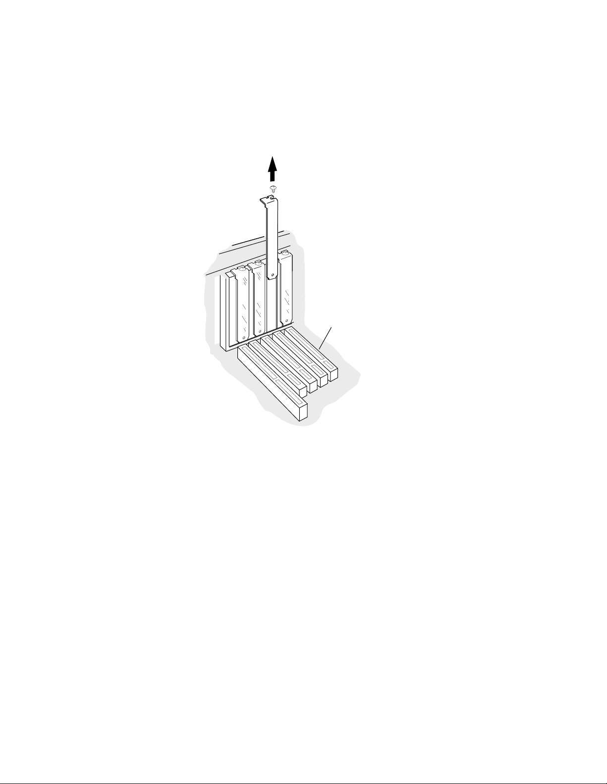
Locate an available PCI slot, and remove the slot cover, as
shown in Figure 3-1. (Refer to the computer user
documen t ation for more information .)
The PCI slot must support bus mastering and conform to PCI
Rev. 2.0 or higher specifications. If th e slot does not meet PCI
Rev 2.0 specifi cations, dedicate an IRQ channel to the slot and
specify le vel trigge ring for the slot.
the computer and any attached devices, and
Caution:
any comput er co mpone nts , to uch th e met a l part of the
!
computer’s power supply to discharge any static
electricity from your clothes and body. (Use a wri st
ground in g strap if you have one.)
To avoid possible damage to the adapter or
3-1
ANA-5910/5930/5940 User’s Guide
.
PCI Slot
Figure 3-1. Removing the Expansion Slot Cover from the
Back of the Computer
5
Care f ully remove the card from i ts antistatic packaging. Hold
the adapte r b y its edges to avoid touching the componen ts or
the conn e c tors.
3-2

Installing the Adapter
6
Align the adapter with the PCI expansion sl ot, and inse rt the
adapter f irmly into the socket, as shown in Fig u re 3-2.
Figure 3-2. Inserti ng the Adapter into the Socket
7
Attach the adapter bracket to the computer chassis. If needed,
use the screw you removed in step 4 on page 3-1.
8
Reassemble the computer and replace the cover on the
comput er case. Refer to the computer user documentation for
instructions.
3-3
ANA-5910/5930/5940 User’s Guide
Connecting the ANA-5910/5930/5940 Adapter to
the Network
Before you can use your ANA-5910/59 30/ 5940 adapter, you must
connect it to an ATM switch.
Connecting to the ANA-5910
Note:
The RJ-45 con nector pinout on the adapter conforms
with th e IBM de fact o s ta ndard. If you r sw i t ch co nn e c to r
pinout is not compatible with this standard, obtain or create
a cable to convert to the required pinout.
To connect the ANA-5910 to an AT M swit ch:
1
Obtain the connecting cable.
2
Connect the RJ-45 c onnector at one en d of t he cable to the R J-45
socket on the ANA-5910.
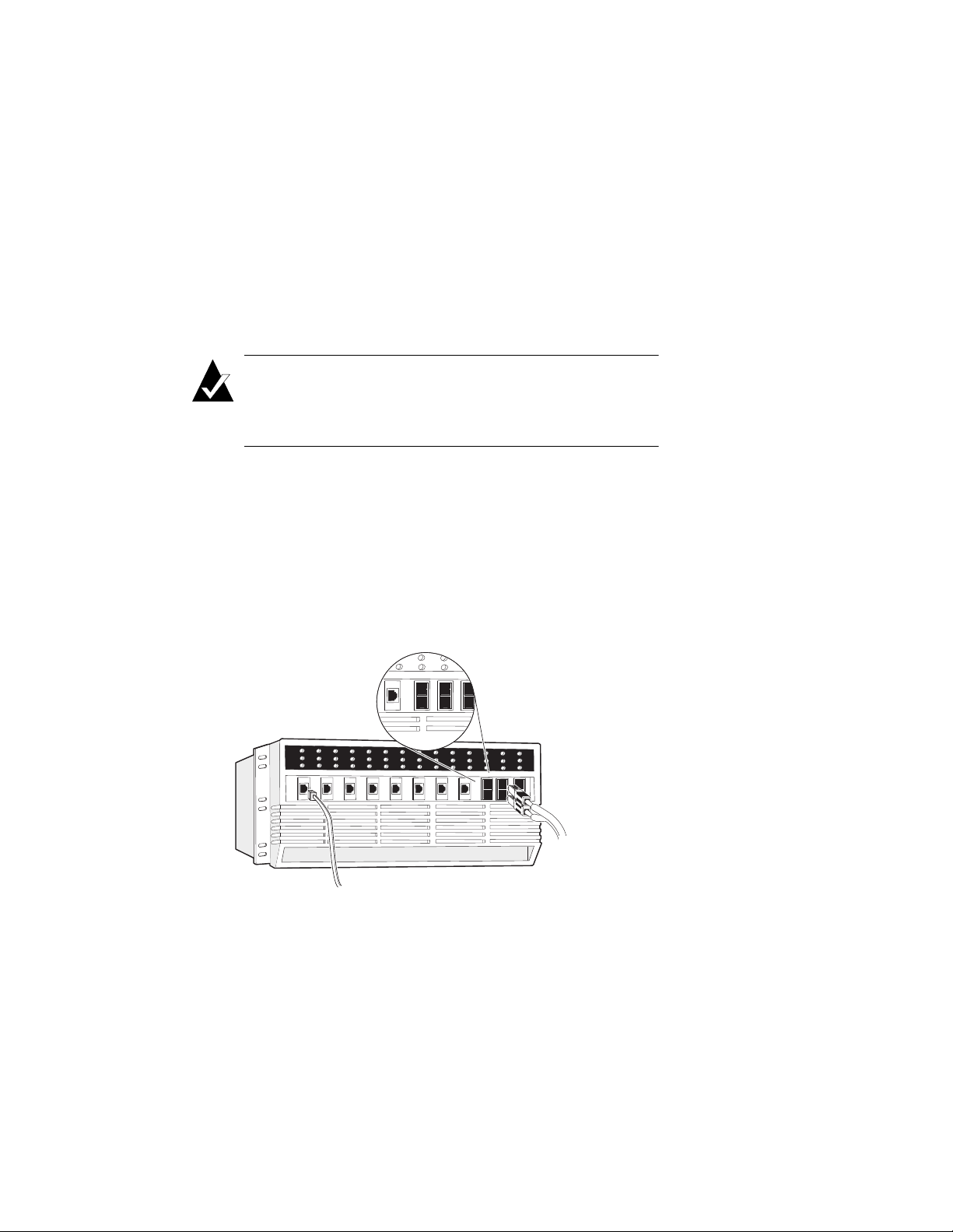
3
Connect the RJ-45 connector at the other end of the cable to the
ATM wall port or di rectly to the RJ- 45 socket on the ATM
switch, as illustr ated in Figure 3-3. See your system
admi ni s tr ator for as sistan ce .
3-4
Figure 3-3. Connecting the UTP/STP Cable to the ATM Switch

Installing the Adapter
Connecting to the ANA-5930
To connect the ANA-5930 to an AT M swit ch
Obtain the connecting cable.
1
Connect the RJ-45 c onnector at one en d of t he cable to the R J-45
2
socket on the ANA-5930.
Caution:
Connect only a UTP 5 cable to the ANA-5930.
!
Connect the RJ-45 connector at the other end of the cable to the
3
ATM wall port or di rectly to the RJ- 45 socket on the ATM
switch, as illustr ated in Figure 3-3. See your system
admi ni s tr ator for as sistan ce .
Connecting to the ANA-5940
To connect the ANA-5940 to an AT M swit ch
Obtain an MMF cable with an SC connector on one end and a
1
connector that matche s your A TM switch on the other end.
Remove the soft rubber cover on the back bracket of the
2
ANA-5940.
Caution:
dust might impair transmissions.
!
Remove the rubber termin ators from the e nds of the MMF
3
cable.
Attach the SC connector on the MMF cable to the MMF
4
connector on the back bracke t of the ANA-5940, as shown in
Always cover open MMF cable connectors, as
3-5

ANA-5910/5930/5940 User’s Guide
Figure 3-4. The connector is keyed and can be attached in one
way onl y .
(
U
L
)
E
1
0
3
6
9
5
M
A
D
E
I
N
U
S
A
Figure 3-4.
5
Attach the oth er end of the MMF cabl e to the ATM wall port or
Attaching the SC Connector of the MMF Cable to the
directly to an MMF connector on the ATM switch (F igure 3-5).
Section of MMF
ATM Adapter ATM Switch
TX
RX
Cable with Markings
RX
TX
Figure 3-5. Connect ing the MMF Cable to the ATM Switch
❒
3-6
ANA-5940

4
▼▼▼▼
Installing ATM Version 4.0x
Software for Windows NT
This chapter explains how to install, use, reconfig ure, and remove
Adaptec ATM software (versions 4.0x) for Windows NT
workstati ons and servers (with versions 4.0 or 3.51).
Installation for Windows NT (version 4.0)
The proce dures below describe installation of LAN Emulation
(LANE) client device drivers and ATM Utilities for a server using
Windows NT 4.0
Note:
For information on how to install these dri vers to
Windows NT 3.51, refer to the
(version 3.51)
section later in this chapter.
Installation for Windows NT
To ensure correct device configuration, install these options in the
following order:
■
LANE drivers
■
A T M Utilities
4-1
ANA-5910/5930/5940 User’s Guide
Install ing LANE Device Drivers
LANE client drivers are installed from the Network Settings dialog
box in the Control Panel. Up to 4 clients (numbered 0 to 3) can be
installed at one time. To configure multiple clients, you must install
the first client (0) before you can install any additional client.
Installing a LANE Client Driver
Follow these procedures for installing a LANE client driver. If you
are installing the Adaptec LANE Client device driver for the first
time, your configuration address number (ELAN numb er) must be
assigne d to (0). Additional drivers can be installed with unique
numbers 1 to 3.
From the Control Panel window, double-click on the Network
1
icon.
Select the Adapters tab fr om the Network Settin g s di alog box.
2
Click on the Add button to add a device driver.
3
Insert th e ALANE Drivers for Windows NT diskette in the
4
diskette drive. Select the Have Di sk button.
Type the drive letter of the diskette drive that contains the
5
ALANE Drivers for Windows NT diskette, and sel ect OK.
Select Adaptec Inc. ATM LANE Adapter, and select OK.
6
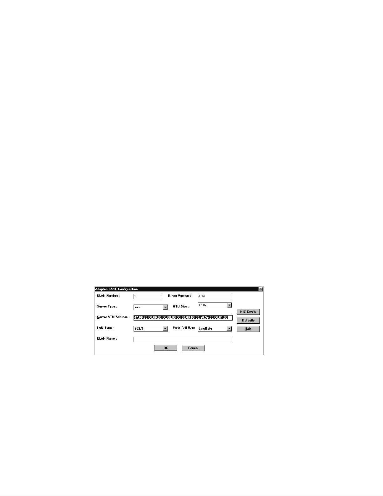
The Adaptec LANE Configuration dialog box appears.
4-2

Installing ATM Version 4.0x Software for Windows NT
Set the editable parameters in the table below (as required),
and se le ct OK when complete.
Parameter Setting
ELAN Number This read-only field contains the
number automatically assigned to the
LAN during installation. The
ANA-5910/5 930/5940 supports up to
four emulated LANs, numbered 0–3.
Driver Version Displays the current version of th e
Adaptec LANE driver.
Server Type Select lecs if the server is a
Configuration Server; select les if the
server is a LAN Emulation Server.
MTU Size Stands for maximum transfer unit .
Select 9234 or 1516. Note tha t 9234
works only if the LES and BUS for this
ELAN also support this selection.
Server AT M Address Enter the A TM address o f the LECS or
of the LES; 20 digit (hex) address,
separated by dots (.). The default
setting is WELL-KNOWN LECS
ADDRESS.
LAN Typ e Select 802.3 if the Ethernet LAN
emulation is to be enabled in the
LANE driver; select 802.5 if Token-
ring LAN emulation is to be enabled.
Peak Cell Rate The default is the Line Rate of the
NIC. The PCR can be stepped down
from the Line Rate. This value is
specified in Mbits/second.
ELAN Name This field is optional. Specify a
character string if the switch supports
this feature. No [space] characters are
allowed in the string.
To change the NIC configuration, select the NIC Config
button.
4-3

ANA-5910/5930/5940 User’s Guide
Enter the following parameters and click OK.
NIC Number Network Interface Card number. The
only available number is (0) at this
time.
UNI Signalling Version Select 3.0 from the drop-down list if
the switch software supports UNI 3.0
signaling; select 3.1 if th e swit ch
supports UNI 3.1 signaling.
Is this a 155 Mbs NIC
Serving 25 Mbs Clients
Select Yes if you have a 155 Mbs NIC
serving 25 Mbs clients. Select No
(default ) i f you are not at 155 Mbs
serving 25 Mbs clients.
The Network Settings dialog box displays the installed
Adaptec LANE adapter in the Installed Adapter Cards lis t b ox.
7
Select OK to exit the Network Settings dialog box.
4-4

Installing ATM Version 4.0x Software for Windows NT
8
Enter Bus Type and Number fr om the dialog box and selec t
OK.
Type Set the Type to PCI when using the
Adaptec card. Default is ISA.
Number Select the bus number slot that the
card is plugged into. The total number
available depends on how your
hardware is configured.
9
Select Close from the Network Control Panel window.
10
If IPX/SPX i s installed on your workstation, the NWLink IPX/
SPX Protocol Configuration dialog box appears. If IPX/SPX is
not installed, this dialog will not appear.
■
Select the adapter that will support the IPX/SPX protocol
from the Ad apter drop-down list.
■
Select Auto Detected from the Frame Type drop-down
list.
■
Select OK.
11
If TCP/IP is installed on your workstation, the TCP/IP
Configuration dialog box appears, requiring that you set other
protocol addresses and informati on. Refer to your Windows
NT user documentation for information about setting up your
TCP/IP configuration, and when you have entered the
necessary TCP/IP data , se lect OK. If you do not have TCP /IP
installed, these configuration screens will not appear.
12
Add additional client s (1 to 3) by follow ing the abov e
procedur es, or select Yes to save and initialize cha nges.
4-5

ANA-5910/5930/5940 User’s Guide
Reconfiguring a LANE Client
To reconfigure a LANE clien:
1
From the Control Panel window, double-click on the Network
icon.
2
From the Network Settings dialog box, select the Adapters tab.
3
Select the LANE adapter you want to re configure, for example,
Adaptec LANE Adapter (ELAN 0), and then select Properties.
4
Change any editable parameter as described in the installation
procedures previously in this chapter.
Removing a LANE Client
To remove the LANE client:
1
From the Control Panel window, double-click on the Network
icon.
2
From the Network Settings dialog box, select the Adapters tab.
3
Select the LANE adapter you want to remove, such as Adaptec
LANE Adapter (ELAN 0), from the I n s ta l le d Adap te r Cards
drop-down list, and then select Remove.
4
Select Yes.
5
In the Network Se ttings dialog box, select Close.
6
Select Yes.
7
If you want to reinstall the adapter you just removed, you
must rest a rt Windows NT a n d f ollow th e pro ce d u res fo r
installing additional clients.
4-6

Installing ATM Version 4.0x Software for Windows NT
Installing The ATM Utilities
To install the Adaptec ATM Utilities
Select Start , Settings, then Control Panel.
1
From th e Control P anel window, click on the Network icon.
2
Select the Protocols tab from the N e t work Se t ti ngs dia lo g b ox.
3
Click the Add button to add a devi ce driver.
4
Insert th e ALANE Utilities for Windows NT diskette in the
5
diskette drive and select Hav e Disk.
Type the drive letter of the diskette, and select OK.
6
Select Ad aptec ATM Utilities, and sel ect OK.The following
7
message appears in the Setup Message dialog box:
Install the NT SNMP service and use configure option to
configure Adaptec ATM SNMP
Select OK. The installation stops, and the Network Settin g s
dialog box appears.
Select Close.
8
4-7

ANA-5910/5930/5940 User’s Guide
Installation for Windows NT (version 3.51)
This sectiondescribes installation of Lan Emulation (LANE) client
device drivers for a Windows NT ATM server using version 3.51.
Install ing LANE Device Drivers
LANE client drivers are installed from the Network Settings dialog
box in the Control Panel. Up to 4 drivers (numbered 0 to 3) can be
installed at one time. To install multiple drivers, you must install
driver 1 (0) before any additional drivers.
Installing a First or Single LANE Client Driver
To install the LANE driver for the first emulated LAN
1
In the Control Panel window click on the Network icon.
2
From the Network Settings di alog box, select Add Adapter .
3
Select <Other> Requires disk from manufacturer from the
bottom of t h e Networ k Adap ter Car d dr o p-do wn lis t, an d th en
select Continue.
4
Insert th e ALANE Drivers for Windows NT diskette in the
diskette drive.
5
Type the drive letter of the diskette drive that contains the
ALANE Drivers for Windows NT diskette, and then select OK.
6
Select Adaptec Inc. ATM LANE Adapter, and then select OK.
The Adaptec LANE Configuration dialog box appears.
4-8

Installing ATM Version 4.0x Software for Windows NT
Set the editable parameters as follows, and select OK when
complete.
Parameter Setting
ELAN Number This read-only field contains the
number automatically assigned to the
LAN during installation. The
ANA-5910/5 930/5940 supports up to
four emulated LANs, numbered 0–3.
Driver Version Displays the current version of th e
Adaptec LANE driver.
Server Type Select lecs if the server is a
Configuration Server; select les if the
server is a LAN Emulation Server.
MTU Size Stands for maximum transfer unit .
Select 9234 or 1516. Note tha t 9234
works only if the LES and BUS for this
ELAN also support this selection.
Server AT M Address Enter the A TM address o f the LECS or
of the LES; 20 digit (hex) address,
separated by dots (.). The default
setting is WELL-KNOWN LECS
ADDRESS.
LAN Typ e Select 802.3 if the Ethernet LAN
emulation is to be enabled in the
LANE driver.
Peak Cell Rate The default is the Line Rate of the
NIC. The PDR could be stepped down
from the Line Rate. This value is
specified in Mbits/second.
ELAN Name This field is optional. Specify a
character string if the switch supports
this feature. No [space] characters are
allowed in the string.
To change the NIC configuration, select the NIC Config
button.
4-9

ANA-5910/5930/5940 User’s Guide
Enter the following parameters and click OK
NIC Number Network Integrated Controller
number. Only available number is (0)
at this time.
UNI Signalling Version Select 3.0 from the drop-down list if
the switch software supports UNI 3.0
signaling; select 3.1 if th e swit ch
supports UNI 3.1 signaling.
Is this a 155 Mbs NIC
Serving 25 Mbs Clients
Select Yes if you have a 155 Mbs NIC
serving 25 Mbs clients. Select No
(default ) i f you are not at 155 Mbs
serving 25 Mbs clients.
The Network Settings dialog box displays the installed
Adaptec LANE adapter in the Installed Adapter Cards lis t b ox.
7
Select OK to exit the Network Settings dialog box.
4-10

Installing ATM Version 4.0x Software for Windows NT
8
Enter Bus Type and Number fr om the dialog box and selec t
OK.
Type Set the Type to PCI when using the
Adaptec card. Default is ISA.
Number Select the bus number slot that the
card is plugged into. The total number
available depends on your hardware
configuration.
9
Select OK from the Network Control Panel window .
10
If IPX/SPX i s installed on your workstation, the NWLink IPX/
SPX Protocol Configuration dialog box appears. If IPX/SPX is
not installed, this dialog box will not appear.
■
Select the adapter that will support the IPX/SPX protocol
from the Ad apter drop-down list.
■
Select Auto Detected from the Frame Type drop-down
list.
■
Select OK.
11
If TCP/IP is installed on your workstation, the TCP/IP
Configuration dialog box appears, requiring that you set other
protocol addresses and informati on. Refer to your Windows
NT user documentation for information about setting up your
TCP/IP configuration. When you have entered the necessary
TCP/IP data, select OK. If you do not have TCP/IP installed,
these configuration screens will not appear.
4-11

ANA-5910/5930/5940 User’s Guide
12
Add additional client s (1 to 3) by follow ing the abov e
procedur es, or Select Restar t Now to save and initialize
changes.
reconfiguring a LANE Client
To reconfigure a LANE client:
1
In the Program Manager’s Main group window, select the
Control Pan el icon.
2
Select the Network icon.
3
Select the LANE adapter you want to re configure, for example,
Adaptec LANE Adapter (ELAN 0), and then select Configure.
4
Change any editable parameter as described in the installation
procedures earlier in this chapter.
5
Select Restart Now to save and initia li ze changes.
Removing a LANE Client
1
In the Program Manager’s Main group window, select the
Control Pan el icon.
2
Select the Network icon.
3
Select the LANE adapter you want to remove, such as Adaptec
LANE Adapter (ELAN 0), from the I n s ta l le d Adap te r Cards
drop-down list, and then select Remove.
4
Select Yes.
5
In the Network Se ttings dialog box, select OK.
6
Select Restart Now to save and initialize cha nges.
4-12

Installing ATM Version 4.0x Software for Windows NT
Installing The ATM Utilities
To install the Adaptec ATM Utilities
In the Program Manager’s Main group window, select the
1
Control Pan el icon.
Select the Network icon.
2
Select Add Adapt er from the Network Settings dialog box.
3
Select <Other> Requires disk from manufacturer from the
4
bottom of t h e Networ k Adap ter Car d dr o p-do wn lis t, an d th en
select Continue.
Insert th e ALANE Utilities for Windows NT diskette in the
5
diskette drive.
Type the drive letter of the diskette drive that contains the
6
diskette with the ATM utilities, and then select OK.
Select Adaptec ATM Utilities, and then select OK.The
7
following message appears in the Setup Message dialog box:
Install the NT SNMP service and use configure option to
configure Adaptec ATM SNMP
When you select OK, the inst allation stops, and the Network
Setting s di alog box appears.
Select Close.
8
4-13

ANA-5910/5930/5940 User’s Guide
Using Device Drivers and Utilities
Stopping ATM Drivers
To stop AT M drivers:
1
If your p a th is no t se t u p , ch a nge to the followi ng direc to ry :
\win n t\sy stem 3 2\adptaatm\bin
2
Stop the driver using the appropriate command below and in
the fol l ow i ng order:
alancnfg -s stops the
aatmcnfg -s stops the
alane.sys
atmo.sys
driver
driver
Starting ATM Drivers
To star t the A TM drivers
1
In the Program Manager’s Main group window, select the
MS-DOS Co mm a nd Pro mpt icon.
The Command Prompt window appears.
1
If your p a th is no t se t u p , ch a nge to the followi ng direc to ry :
\win n t\sy stem 3 2\adptaatm\bin
2
Start the drivers you need by entering the commands in the
following order:
aatmcnfg starts the
you
want to register with an ATM switch (for
example, in back-to-bac k connections); use the
(-a) option if your switch does not support ILMI
address registration
alancnfg starts the
atmo. sys
do not
want to use SVCs and if you do not
alane.sys
driver; use the -q option if
driver
Various command-li ne options are available for each utilit y. You can
get help for any of the commands listed in this appendix by typing
-h after the utility, for example:
aatmcnfg -h
4-14

aatmcnfg.exe
Installing ATM Version 4.0x Software for Windows NT
aatmcnfg.exe
The
utility is used for configuring the
atmo.sys
driver.
The following is the syntax for using this utility:
aatmcnfg [-f ConfigFile] -[x n] -[s | d | p | q | a]
Options:
-s shutdown
-d debug
-p pri nt status
-q no signall ing
-a no address registration
-x n delete PVC channel n
Use the -q option only if you do not want to use SVCs and if you do
not want to register with a switch, as in back-to-back connec tions or
when running diagnostics. Use the -a option if your switch does not
support address registration. Use the -f Conf igF i le option to start the
atmo.sy s
driver with a database file othe r than the default
for example,
Note:
trial.db
.
When you run the utility
aatmcnfg
without op tions,
base.db
,
the driver registers with the switch. If the driver fails to
register with the switch, enter aa t mc n fg -s to stop the driver
then try starting it again.
4-15

ANA-5910/5930/5940 User’s Guide
aatmdiag.exe
aatmdiag.exe
The
following is the syntax for using this utility:
aatmdiag [-option “[command][; command]”]
Options:
-c number specifies the controller number
-d <0-1> indicates the log level for loop command
-f <filename>1 specifies the input file (i.e., if you created
-l <log Filename> specifies the log file to use
-h display this infor mation
Commands:
Any command listed with the 'help' command when in
'aatmdiag'. Type 'aatmdiag help' for the list of valid commands.
utility is used to diagnose the ATM adapter. The
1
0 = Inhibit pass messages (default)
1 = Print pass messages
a batch file with the tests listed in the file)
Type help at the ADM:x> prompt for addi tional help in the
aatmdiag.ex e
utility.
ADM:0> help
1
Use the -f option and the file name if you created a batch file with the tests
listed in the file.
4-16

Installing ATM Version 4.0x Software for Windows NT
General comm a nds supported:
info Displays network interface controller
general information.
log_level Set the diagnostics log level.
loop Loop on specified list of diagnostic
commands.
quit | exit Quit ATM diagnostic program.
Specific diagnostic test commands supported:
selftest Execute Self Test diagnostic tests.
sar_mem_e Execute extended SAR Memory
diagnostic tests.
atm_external Execute ATM External Loopback tests
(loopback cable required).
alanecnfg.exe
alanecnfg.exe
the
The following is the syntax for using this utility.
utility is used to start the alane.sys driver.
-s stop LEC
-p LEC status
-pv VCC status
-pa arp status
-t Statistics
4-17

ANA-5910/5930/5940 User’s Guide
aatmcons.exe
atmoconsole.exe
The
messages on an MS-DOS screen. The following is the syntax for
using this utility (no online help is available for this utility):
aatmcons starts the console on the current MS-DOS
start aatmcons starts the console on the separate MS-DOS
Ctrl + C stops atmoconsole and exits the separate
utility is used to display console error
screen
screen
MS-DOS screen
4-18

Locating Files and Directories
The following table lists the files that are copied onto your hard
drive when you install the LA N Em ulati on (LANE ) client dr iver s.
The specific files that are installed depend on which driver you
installed.
The following files are copied and subdirectories created:
Default Directory Structure File Description
systemroo t
\
systemroot
\
\drivers
winroot
\
atm\bin
(These files must be in
this directory.)
winroot
\
atm\config
\
system32
\system32
\system32\adpta
\system32\adpta
aatmsnmpd. dll
adptcnfg.d ll
oemnadx.i nf
oemnxpn.i nf
adptalan. dl l
atmo.sys
natm.sys
alane.sys
aatmcnfg.exe
alancnfg.exe
aatmdiag.exe
aatmcons.exe
aatmndd.exe
aatmui.exe
console.ico
diagcmd1.ico
selftest.ico
base.db
alanex.db
SNMP agent driver
A TM configuration driver
ATM OEM installation file
Utilities OEM installation
file
LANE configuration driver
ATM driver; includes CIP
The link for the
driver
LANE driver
ATM startu p p rogram
LANE startup program
ATM adapter diagnost ic
program
Displays console error
messages
Debug utility
GUI interface for A TM
services, start/stop services
Icon files for executables.
Yo ur workstation’s specific
database files for the
drivers
atmo.sys


5
▼▼▼▼
Installing ATM Version 2.0x
Drivers for Windows NT
This chapter explains how to install, use, reconfig ure, and remove
Adaptec ATM software (versions 2.0x) for Windows NT
workstati ons and servers (with versions 4.0 or 3.51).
Installation for Windows NT (version 4.0)
The proce dures below describe installation of ATM, Classical IP
(CIP), and Lan Emulation (LANE) client device drivers when setting
up a Windows NT ATM server using version 4.0.
Note:
For information on how to install these dri vers to
Windows NT 3.51, refer to the
(version 3.51)
section later in this chapter.
Installation for Windows NT
To ensure correct device configuration, install these drivers in the
following order:
■
Classical IP (CIP) client drivers
■
LANE drivers
■
CIP ARP server (optional drivers, purchased separately)
5-1

ANA-5910/5930/5940 User’s Guide
Installing CIP Client Drivers
Install these drivers before instal ling the LANE drivers and the CIP
ARP server.
From the Control Panel window, double-click on the Network
1
icon.
Select the Adapters tab from the Networ k Settings dialog box.
2
Insert Device Driver for Windows NT Disk 1 in the diskette drive.
3
Select the Have Disk butt on.
Type the drive letter of the diskette drive that contains Device
4
Driver for Windows NT Disk 1, and then sele ct OK.
Select Adaptec Inc.ATM ANA-59x0 Adapter(CIP), and then
5
select OK.
The Adaptec A T M Base Driver/CIP Configuration dialog box
appears.
Add PVCs as follows:
6
5-2

Installing ATM Versi on 2.0x Drivers for Windows NT
Select Add next to the PVCs list box. The PVC Configuration
dialog box appears.
Set the parameters in the dialog b ox as follows, and sele ct OK:
Parameter Setting
VCI Typ e a number from 32 to 1023.
Null Encapsulation Select the check box to access another
ATM adapter that uses null
encapsulation or VC multiplexing. If
you do not select this check box, the
default transmission method, LLC/
SNAP (RFC 1577), is used.
Remote IP address If you selected the Null Encapsulation
check box, the Remote IP address
parameter appears. Ent e r th e IP
address of the other ATM adapter with
which you want to communicate.
7
Change any of the editable parameters in the Adaptec ATM
Base Driver/CIP Configuration dialog box, and select OK.
Parameter Setting
Directory This read-only field contains the
directory where th e ATM softwar e is
located.
Port Index Leave this parameter at its 0 default
setting;
implemented at this time.
IBM Concentrator 8282 Select the check box if you have an
ANA-5910 and are connecting to an
IBM Concentra to r 8282.
Autostart Base driver Select the check box to automatically
start the base driver at boot-up.
the Port Index parameter is not
5-3

ANA-5910/5930/5940 User’s Guide
Parameter Setting
Autostart CIP Select the check box to automatically
start the CIP client driver at boot-up.
Back to Back PVC Selec t the chec k box to use the CIP
client in back-to-back mode without
involving the switch.
AARP server address Ent er the address of the CIP ARP
server; 20-byte, 40 hex characters. If
the ARP server address has not been
established, use the default setting.
PVCs Use the PVCs list box to add, change
or remove PVCs.
8
Select PCI from the Bus Type drop-down list in the Bus
Location di alog box, and select the bus number to which the
ATM adapte r is at tach ed fr om th e Bus Numb er dr o p-down li st.
Then select OK.
The installer copies the base driver to the following directory:
drive:\systemroot
\System32\drivers
where
drive = boot drive letter
systemroot = SystemRoot directory
9
When the Setup Message dialog box appears, insert Device
Driver for Windows NT Disk 2 in the diskette drive, and select
OK.
10
If NT SNMP has not been in stalled on your work station, the
Setup Message dialog box appears advising you to install the
NT SNMP service and to configure the Adaptec ATM SNMP
agent. Select OK.
When the Network Settings dialog box appears, the ATMO
(base) Driver appears in the Installed Network Software list
box, and the Adaptec ATM adapter appears in the Installed
Adapter Car ds list box.
11
Select Close to exit the Network Settings dialog box.
5-4

Installing ATM Versi on 2.0x Drivers for Windows NT
12
If TCP/IP is installed on your workstation, the TCP/IP
Configuration dialog box appears, requiring that you set other
protocol addresses and informati on. Refer to your Windows
NT user documentation for information about setting up your
TCP/IP configuration, and when you have entered the
necessary TCP/IP data , se lect OK. If you do not have TCP/IP
installed, these configuration screens will not appear.
13
Select Yes to sav e and init ializ e chan ges .
Install ing LANE Device Drivers
Ensure that CIP drivers have been installed
Note:
bef o re LANE client drivers. If no CIP drivers have
been installed, follow the procedures in the previous
section to install them.
LANE client drivers are installed from the Network Settings dialog
box in the Control Panel. Up to 4 clients (numbered 0 to 3) can be
installed at one time.You must install the first cli e nt (0) before you
can install any additional client.
Installing a LANE Client Driver
1
From the Control Panel window, double- click on the Network
icon.
2
From the Network Settings dialog box, select the Adapters tab.
3
Click on the Add button to add a device driver.
4
Insert th e LAN Emulation Client diskette in the diskette drive.
5
Select the Have Disk butt on.
6
Select the drive letter of the di skette drive that contains the
LAN Emulation Client diskette, and then select OK.
7
Select Ad apt ec Inc . ATM LANE Adapter, and then select OK.
5-5

ANA-5910/5930/5940 User’s Guide
The Adaptec LANE Configuration dialog box appears.
Set the editable parameters as follows, and select OK.
Parameter Setting
ELAN Number This read-only field contains the
number automatically assigned to the
LAN during installation. The
ANA-5910/5 930/5940 supports up to
four emulated LANs, numbered 0–3.
Server AT M Address Enter the A TM address o f the LECS or
of the LES; 20-digit (hex) address,
separated by dots (.). The default
setting is WELL-KNOWN LECS
ADDRESS.
Server Type Select lecs if the server is a
Configuration Server; select les if the
server is a LAN Emulation Server.
Switch Type Select 3.0 from the drop-down list if
the switch software supports UNI 3.0
signaling; select 3.1 if th e swit ch
supports UNI 3.1 signaling.
LAN Typ e Select 802.3 from the dr op-d ow n lis t i f
Ethernet LAN emulation is to be
enabled in the LANE driver; select
802.5 if Token-ring LAN emulat io n is
to be enabled .
5-6

Installing ATM Versi on 2.0x Drivers for Windows NT
Parameter Setting
MTU Size Stands for maximum transfer unit .
Select 9234 or 1516 from the dro p-
down list.
Peak Cell Rate The peak cell rate is the rate, in
Mbits/sec, at which cells are
transferred. Ent e r a number from 0
through 353208. The 0 val u e defaults
to the full line rate of the NIC. Use
58962 for 25 Mbits/sec; use 353208 for
155 Mbits/sec.
ELAN Name Enter a name if the client’s LECS
requires ELAN name regist ration;
32 characters maximum; no spaces.
Autostart ELAN Select the check box to automatically
start the LANE driver at boot-up.
The Network Settings dialog box displays the installed
Adaptec LANE adapter in the Installed Adapter Cards lis t b ox.
8
Select OK to exit the Network Settings dialog box.
9
If IPX/SPX i s installed on your workstation, the NWLink IPX/
SPX Protocol Configuration dialog box appears. If IPX/SPX is
not installed, this dialog will not appear.
■
Select the adapter that will support the IPX/SPX protocol
from the Ad apter drop-down list.
■
Select Auto Detected from the Frame Type drop-down
list.
■
Select OK.
10
If TCP/IP is installed on your workstation, the TCP/IP
Configuration dialog box appears, requiring that you set other
protocol addresses and informati on. Refer to your Windows
NT user documentation for information about setting up your
TCP/IP configuration, and when you have entered the
necessary TCP/IP data , se lect OK. If you do not have TCP/IP
installed, these configuration screens will not appear.
11
Add additional client s (1 to 3) by follow ing the abov e
procedur es, or select Yes to save and initialize changes.
5-7

ANA-5910/5930/5940 User’s Guide
Reconfiguring a LANE Client
To reconfigure a LANE client:
1
From the Control Panel window, double-click on the Network
icon.
2
From the Network Settings dialog box, select the Adapters tab.
3
Select the LANE adapter you want to re configure, for example,
Adaptec LANE Adapter (ELAN 0), and then select Properties.
The Adaptec LANE Configuration dialog box appears.
4
Set the editable parameters as described in the sections above.
Removing a LANE client
1
From the Control Panel window, double-click on the Network
icon.
2
From the Network Settings dialog box, select the Adapters tab.
3
Select the LANE adapter you want to remove, such as Adaptec
LANE Adapter (ELAN 0), from the I n s ta l le d Adap te r Cards
drop-down list, and then select Remove.
4
Select Yes.
5
In the Network Se ttings dialog box, select Close.
6
Select Yes to save and initializ e change s .
5-8

Installing ATM Versi on 2.0x Drivers for Windows NT
Installing the CIP ARP Server (Optional)
If your workstation will function as the ATM CIP ARP server, you
must install the CIP client software (which must be purchased
separately) and the ATM CIP ARP server driver. Follow the
procedures below to install the ATM CIP ARP server software.
From the Control Panel window, double-click on the Network
1
icon.
From the Network Settings di alog box, select the Protocol tab.
2
Click on Add to add a protocol.
3
Select the Have Disk butt on.
4
Insert th e RF C 1577 CIP ARP Server diskette i n the di skette
5
drive.
Type the drive l etter of the diskette drive that contains the RFC
6
1577 CIP ARP Server diskette, and then select OK.
Select Ada pte c ATM ARP Server, and then select OK.
7
The Adaptec A T M ARP Server Configuration dialog box
appears.
5-9

ANA-5910/5930/5940 User’s Guide
Set the parameters in the dialog b ox as follows, and sele ct OK:
Parameter Setting
IP Address Enter the logical IP subnet where this
ATM ARP server resides; 15
characte r s maxi mum; 4 bytes, dotted
decimal format; for example,
192.9.200.0
Subnet Mask Enter the IP subnetwork mask for the
ATM adapter; 15 characters
maximum; 4 bytes, dotted decimal
format; for example, 255.255.255.0
Autostart ARP Server Select the check box to automatically
start the ARP server driver at boot-up.
8
Remove the RFC 1577 CIP ARP Server diskette fr om the
diskette drive.
9
Select Close to exit the Network Settings dialog box.
10
Select Yes to save and initialize changes .
Determining the CIP ARP Server Address
Enter co mma nds such as aatmcnfg should be entered
Note:
from the MS-DOS command prompt, which you can access
by selecting the MS-DOS Command Prompt icon in
Program Manager’s Main group window.
To obtain th e 2 0-b y t e , ATM ARP se rver ad d res s
The ATM driver should be started and re gistered to
Note:
the switch.
1
On the ARP server, enter the fo llowing command from the
directory (
\etc\opt\adptaatm\bin
) where the ATM CIP software
was installed:
aatmcnfg -p
The ATM address for the ARP server appears, for example,
39.11.22.11.22.11.22.00.00.11.22.11.22.00.00.d1.00.04.45.00
5-10

Installing ATM Versi on 2.0x Drivers for Windows NT
2
Write this address down. Then replace the 20th byte (the final
byte, which is 00 ) with 03. Use this altered ad dress as the ATM
ARP server address when you install the CIP client software
on all clie nt workstations in the LIS.
The ATM ARP server address consists of the following:
■
The firs t 1 3 b y t e s are fro m the ATM switch. (R e f e r to th e
switch do cumen tat i on .)
■
The next 6 bytes are the MAC address (E SI address) of the
adapter installed in the ATM ARP server.
The MAC address also appears when you use the
aatmcnfg -p command.
■
The 20th byte (the A TM ARP sele ctor) must be diff erent th an
the CIP clien t selector and the ATM selector. Adaptec ATM
drivers use the followi ng default selectors:
– ARP selector (
– CIP clien t selector (
–ATM selector (
aarp.sys
aatm
acip
): 00
): 03
): 02
Reconfiguring the CIP ARP Server
To reconfigure the CIP ARP server:
1
From the Control Panel window, double-click on the Network
icon.
2
From the Network Settings di alog box, select the Services tab.
3
Select AARP Server, and then select Properties.
The Adaptec A T M ARP Server Configuration dialog box
appears.
5-11

ANA-5910/5930/5940 User’s Guide
Make changes as described in the installation section.
4
Select Close to exit the Network Settings dialog box.
5
Select Yes to save and initialize changes .
Removing the CIP ARP Server
1
From the Control Panel window, double-click on the Network
icon.
2
From the Network Settings di alog box, select the Service tab.
3
Select AARP Server and then select Remove.
4
Select Yes.
5
In the Network Se ttings dialog box, select Close.
6
Select Yes to save and initialize changes .
5-12

Installing ATM Versi on 2.0x Drivers for Windows NT
Installation for Windows NT (version 3.51)
The procedures below describe installation of ATM, Classical IP
(CIP), and Lan Emulation (LANE) client device drivers for a
Windows NT ATM server using vers ion 3.51. To ensure correct
device configuration, instal l these dr iver s in the following order:
■
Classical IP (CIP) client drivers
■
LANE drivers
■
CIP ARP server (optional drivers, purchased separately)
Installing CIP Client Drivers
To install CIP client drivers
1
In the Program Manager’s Main group window, select the
Control Pan el icon.
2
Select the Network icon.
3
Select Add Adapt er.
4
Select <Other> Requires disk from manufacturer from the
Network Adap ter Card drop-down list, and then select
Continue.
5
Insert Device Driver for Windows NT Disk 1 in the diskette drive.
6
Type the drive letter of the diskette drive that contains Device
Driver for Windows NT Disk 1, and then sele ct OK.
7
Select Adaptec Inc.ATM ANA-59x0 Adapter(CIP), and then
select OK.
5-13

ANA-5910/5930/5940 User’s Guide
The Adaptec A T M Base Driver/CIP Configuration dialog box
appears.
8
Add PVCs as follows:
Select Add next to the PVCs list box. The PVC Configura tion
dialog box appears.
Set the parameters in the dialog b ox as follows, and sele ct OK:
Parameter Setting
VCI Typ e a number from 32 to 1023.
5-14

Installing ATM Versi on 2.0x Drivers for Windows NT
Parameter Setting
Null Encapsulation Select the check box to access another
ATM adapter that uses null
encapsulation or VC multiplexing. If
you do not select this check box, the
default transmission method, LLC/
SNAP (RFC 1577), is used.
Remote IP address If you selected the Null Encapsulation
check box, the Remote IP address
parameter appears. Ent e r th e IP
address of the other ATM adapter with
which you want to communicate.
9
Change any of the editable parameters in the Adaptec ATM
Base Driver/CIP Configuration dialog box, and select OK, or,
to accept the default values, simply select OK. To reset to
default p a rameters , se lect Defaults.)
Parameter Setting
Directory This read-only field contains the
directory where th e ATM softwar e is
located.
Port Index Leave this parameter at its 0 default
setting;
implemented at this time.
IBM Concentrator 8282 Select the check box if you have an
ANA-5910 and are connecting to an
IBM Concentra to r 8282.
Autostart Base driver Select the check box to automatically
start the base driver at boot-up.
Autostart CIP Select the check box to automatically
start the CIP client driver at boot-up.
Back to Back PVC Selec t the chec k box to use the CIP
client in back-to-back mode without
involving the switch.
AARP server address Enter the address of the CIP ARP
server; 20-byte, 40 hex characters. If
the ARP server address has not been
established, use the default setting.
PVCs Use the PVCs list box to add, change
or remove PVCs.
the Port Index parameter is not
5-15

ANA-5910/5930/5940 User’s Guide
10
Select PCI from the Bus Type drop-down list in the Bus
Location di alog box, and select the bus number to which the
ATM adapte r is at tach ed fr om th e Bus Numb er dr o p-down li st.
Then select OK.
The installer copies the base driver to the following directory:
drive:\systemroot
where
drive = boot drive letter
systemroot = SystemRoot directory
11
When the Setup Message dialog box appears, insert Device
Driver for Windows NT Disk 2 in the diskette drive, and select
OK.
12
If NT SNMP has not been in stalled on your work station, the
Setup Message dialog box appears advising you to install the
NT SNMP service and to configure the Adaptec ATM SNMP
agent. Select OK.
When the Network Settings dialog box appears, the ATMO
(base) Driver appears in the Installed Network Software list
box, and the Adaptec ATM adapter appears in the Installed
Adapter Car ds list box.
13
Select OK to e xi t the Network Settings dialog box .
14
If TCP/IP is installed on your workstation, the TCP/IP
Configuration dialog box appears, requiring that you set other
protocol addresses and informati on. Refer to your Windows
NT user documentation for information about setting up your
TCP/IP configuration, and when you have entered the
necessary TCP/IP data , se lect OK. If you do not have TCP /IP
installed, these configuration screens will not appear.
\System32\drivers
15
Select Restart Now.
5-16

Installing ATM Versi on 2.0x Drivers for Windows NT
Install ing LANE Device Drivers
Ensure that CIP drivers have been installed prior
Note:
to LANE client drivers. If no CIP drivers have been
installed, follow the procedures in the previous
section to install them.
LANE client drivers are installed from the Network Settings dialog
box in the Control Panel. Up to 4 drivers (numbered 0 to 3) can be
installed at one time. Yo u must install the first driver (0) before you
can install an additional driver .
Installing a LANE Client Driver
In the Program Manager’s Main group window, select the
1
Control Pan el icon.
Select the Network icon.
2
Select Add Adapt er from the Network Settings dialog box.
3
Select <Other> Requires disk from manufacturer from the
4
bottom of t h e Networ k Adap ter Car d dr o p-do wn lis t, an d th en
select Continue.
Insert th e LAN Emulation Client diskette in the diskette drive.
5
Type the drive lett er of the dis kette drive that contai ns the LAN
6
Emulation Client disk e t te , an d th e n se l ect OK.
Select Adapte c Inc . ATM LANE Adapter, and then select OK.
7
5-17

ANA-5910/5930/5940 User’s Guide
The Adaptec LANE Configuration dialog box appears.
Set the following editable parameters as follows, and select
OK:
Parameter Setting
ELAN Number This read-only field contains the
number automatically assigned to the
LAN during installation. The
ANA-5910/5 930/5940 supports up to
four emulated LANs, numbered 0–3.
Server AT M Address Enter the A TM address o f the LECS or
of the LES; 20-by te, 40 hex characters;
dotted decimal format. The default
setting is WELL-KNOWN LECS
ADDRESS.
Server Type Select lecs from the drop-down list if
the server is a LAN Emulation
Configuration Server; select les if the
server is a LAN Emulation Server.
Switch Type Select 3.0 from the drop-down list if
the switch software supports UNI 3.0
signaling; select 3.1 if th e swit ch
supports UNI 3.1 signaling.
5-18

Installing ATM Versi on 2.0x Drivers for Windows NT
Parameter Setting
LAN Typ e Select 802.3 from the dr op-d ow n lis t i f
Ethernet LAN emulation is to be
enabled in the LANE driver; select
802.5 if Token-ring LAN emulat io n is
to be enabled .
MTU Size Stands for maximum transfer unit .
Select 9234 or 1516 from the dro p-
down list.
Peak Cell Rate The peak cell rate is the rate, in
Mbits/sec, at which cells are
transferred. Ent e r a number from 0
through 353208. The 0 val u e defaults
to the full line rate of the NIC. Use
58962 for 25 Mbits/sec; use 353208 for
155 Mbits/sec.
ELAN Name Enter a name if the client’s LECS
requires ELAN name regist ration;
32 characters maximum; no spaces.
Autostart ELAN Select the check box to automatically
start the LANE driver at boot-up.
The Network Settings dialog box displays the installed
Adaptec LANE adapter in the Installed Adapter Cards lis t b ox.
8
Select OK to exit the Network Settings dialog box.
9
If IPX/SPX i s installed on your workstation, the NWLink IPX/
SPX Protocol Configuration dialog box appears. If IPX/SPX is
not installed, this dialog box will not appear.
■
Select the adapter that will support the IPX/SPX protocol
from the Ad apter drop-down list.
■
Select Auto Detected from the Frame Type drop-down
list.
■
Select OK.
10
If TCP/IP is installed on your workstation, the TCP/IP
Configuration dialog box appears, requiring that you set other
protocol addresses and informati on. Refer to your Windows
NT user documentation for information about setting up your
TCP/IP configuration, and when you have entered the
5-19

ANA-5910/5930/5940 User’s Guide
necessary TCP/IP data , se lect OK. If you do not have TCP/IP
installed, these configuration screens will not appear.
11
Add additional clients by following the above procedures, or
select Restart Now to save and initialize changes.
reconfiguring a LANE Client
To reconfigure a LANE client:
1
In the Program Manager’s Main group window, select the
Control Pan el icon.
2
Select the Network icon.
3
Select the LANE adapter you want to re configure, for example,
Adaptec LANE Adapter (ELAN 0), and then select Configure.
The Adaptec LANE Configuration dialog box appears.
4
Set the editable parameters as described in the above sections.
5
Select Restart Now to save and initia li ze changes.
Removing a LANE client
1
In the Program Manager’s Main group window, select the
Control Pan el icon.
2
Select the Network icon.
3
Select the LANE adapter you want to remove, such as Adaptec
LANE Adapter (ELAN 0), and then select Remove.
4
Select Yes.
5
In the Network Se ttings dialog box, select OK.
6
Select Restart Now to save and initialize changes.
5-20

Installing ATM Versi on 2.0x Drivers for Windows NT
Installing the CIP ARP Server (Optional)
If your workstation will function as the ATM CIP ARP server, you
must install the CIP client software (purchased separately) and the
ATM CIP ARP server driver.
To install the ATM CIP ARP server software
In the Program Manager’s Main group window, select the
1
Control Pan el icon.
Select the Network icon.
2
Select Add Softwa re from th e Ne t work Se t tings di al o g b o x.
3
Select <Other> Requires disk from manufacturer from the
4
bottom of the Network Software drop-down list, and then
select Continue.
Insert th e RF C 1577 CIP ARP Server diskette i n the di skette
5
drive.
Type the drive l etter of the diskette drive that contains the RFC
6
1577 CIP ARP Server diskette, and then select OK.
Select Ada pte c ATM ARP Server, and then select OK.
7
The Adaptec A T M ARP Server Configuration dialog box
appears.
5-21

Set the parameters in the dialog b ox as follows, and sele ct OK:
Parameter Setting
IP Address Enter the logical IP subnet where this
ATM ARP server resides; 15
characte r s maxi mum; 4 bytes, dotted
decimal format; for example,
192.9.200.0
Subnet Mask Enter the IP subnetwork mask for the
ATM adapter; 15 characters
maximum; 4 bytes, dotted decimal
format; for example, 255.255.255.0
Autostart ARP Server Select the check box to automatically
start the ARP server driver at boot-up.
8
Remove the RFC 1577 CIP ARP Server diskette fr om the
diskette drive.
9
Select OK to exit the Network Settings dialog box.
10
Select Restart Now to save and initiali ze changes.

Installing ATM Versi on 2.0x Drivers for Windows NT
Determining the CIP ARP Server Address
Commands su ch as aatmcnfg should be entered from
Note:
the MS-DOS command prompt, which you can access by
selecting the M S -D O S C om m and Prompt icon in P rogram
Manager’s Main group window.
To obtain th e 2 0-b y t e , ATM ARP se rver ad d res s
The ATM driver should be started and re gistered to
Note:
the switch.
1
On the ARP server, enter the fo llowing command from the
directory (
\etc\opt\adptaatm\bin
was installed:
aatmcnfg -p
The ATM address for the ARP server appears, for example,
39.11.22.11.22.11.22.00.00.11.22.11.22.00.00.d1.00.04.45.00
2
Write this address down. Then replace the 20th byte (the final
byte, which is 00 ) with 03. Use this altered ad dress as the ATM
ARP server address when you install the CIP client software
on all clie nt workstations in the LIS.
) where the ATM CIP software
The ATM ARP server address consists of the following:
■
The firs t 1 3 b y t e s are fro m the ATM switch. (R e f e r to th e
switch do cumen tat i on .)
■
The next 6 bytes are the MAC address (E SI address) of the
adapter installed in the ATM ARP server.
The MAC address also appears when you use the
aatmcnfg -p command.
■
The 20th byte (the A TM ARP sele ctor) must be diff erent th an
the CIP clien t selector and the ATM selector. Adaptec ATM
drivers use the followi ng default selectors:
– ARP selector (
aarp.sys
– CIP clien t selector (
–ATM selector (
aatm
acip
): 00
): 03
): 02
5-23

ANA-5910/5930/5940 User’s Guide
Reconfiguring the CIP ARP Server
To reconfigure the CIP ARP server:
1
In the Program Manager’s Main group window, select the
Control Pan el icon.
2
Select the Network icon.
3
From th e Installed Network Softwar e lis t, select AARP Ser ver,
and then select Configure.
The Adaptec A T M ARP Server Configuration dialog box
appears.
4
Select OK to exit the Network Settings dialog box.
5
Select Restart Now to save and intialize changes.
5-24

Installing ATM Versi on 2.0x Drivers for Windows NT
Using Device Drivers and Utilities
Stopping ATM Drivers
To stop AT M driver:
Note:
PVCs and other configuration information not stored
in the database files are lost when you stop the drivers.
1
If your p a th i s not set up, cha n ge to the di re ct o ry where you
install e d the sof tware.
2
Stop the driver using the appropriate command below and in
the fol l ow i ng order:
alanecnfg -s stops the
acipcnfg -s stops the Classical IP port ion of the
atmo.sys
aarpcnfg -s stops the
the ATMARP server)
aatmcnfg -s stops the
alane.sys
driver
aarp.sys
atmo.sys
driver
driver (only needed on
driver
Starting ATM Drivers
To star t the A TM driver:
1
In the Program Manager’s Main group window, select the
MS-DOS Co mm a nd Pro mpt icon.
The Command Prompt window appears.
2
Change to the directory where you installed the software.
5-25

ANA-5910/5930/5940 User’s Guide
3
Start the drivers you need to use by entering th e command and
in the following order:
aatmcnfg starts the
do not
you
atmo. sys
want to use SVCs and if you do not
driver; use the -q option if
want to register with an ATM switch (i.e., in
back-to-back connections); use the -a option if
your switch does not support ILMI address
registration
aarpcnfg starts the
aarp.sys
driver (only needed on the
ATMARP server)
acipcnfg starts the Classical IP part of
alanecnfg starts the
alane.sys
driver.
atmo.sys
Various command-li ne options are available for each utilit y. You can
get help for any of the commands listed in this appendix by typing
-h after the utility, for example:
aatmcnfg -h
aarpcnfg.exe
aarpcnfg.exe
The
utility is used for configuring the
The following is the syntax for using this utility:
aarpcnfg [-f ConfigFile] -[s | d]
Options:
-s shut down
-d debug
aarp.sys
driver.
Use the -f ConfigFile option to start the
database f ile other than th e def a u lt
5-26
aarp.db
aarp.sys
.
driver with a

aatmcnfg.exe
Installing ATM Versi on 2.0x Drivers for Windows NT
aatmcnfg.exe
The
utility is used for configuring the
atmo.sys
driver.
The following is the syntax for using this utility:
aatmcnfg [-f ConfigFile] -[x n] -[s | d | p | q | a]
Options:
-s shutdown
-d debug
-p pri nt status
-q no signall ing
-a no address registration
-x n delete PVC channel n
Use the -q option only if you do not want to use SVCs and if you do
not want to register with a switch, as in back-to-back connec tions or
when running diagnostics. Use the -a option if your switch does not
support address registration. Use the -f Conf igF i le option to start the
atmo.sy s
driver with a database file othe r than the default
for example,
Note:
trial.db.
When you run the utility
aatmcnfg
without op tions,
base.db
,
the driver registers with the switch. If the driver fails to
register with the switch, enter aa t mc n fg -s to stop the driver
then try starting it again.
aatmdiag.exe
aatmdiag.exe
The
The following is the syntax for using this utility:
aatmdiag [-option “[command][; command]”]
1
Use the -f option and the file name if you created a batch file with the tests
listed in the file.
utility is used for diagnosing the ATM adapter.
1
5-27

ANA-5910/5930/5940 User’s Guide
Options:
-c number specifies the controller number
-d <0-1> indicates the log level for loop command
0 = Inhibit pass messages (default)
1 = Print pass messages
-f <filename>1 specifies the input file (i.e., if you created
a batch file with the tests listed in the file)
-l <log Filename> specifies the log file to use
-h display this infor mation
Command s:
Any command listed with the 'help' command when in
'aatmdiag'. Type 'aatmdiag help' for the list of valid
commands.
Type help at the ADM: x> prompt for additional help while in the
aatmdiag.exe
utility.
ADM:0> help
General comm a nds supported:
info Displays network interface controller
general information.
log_level Set the diagnostics log level.
loop Loop on specified list of diagnostic
commands.
quit | exit Quit ATM diagnostic program.
Specific diagnostic test commands supported:
selftest Execute Self Test diagnostic tests.
sar_mem_e Execute extended SAR Memory
diagnostic tests.
atm_external Execute ATM External Loopback tests
(loopback cable required).
5-28

Installing ATM Versi on 2.0x Drivers for Windows NT
aatmcons.exe
atmoconsole.exe
The
utility is used to display console error
messages on an MS-DOS screen. The following is the syntax for
using this utility (note that there is no online help available for this
utility):
atmoconsole st arts the console on the current MS-DOS screen
start
atmoconsole
star ts the console on the separate MS-DOS
screen
Ctrl + C stops atmoconsole and exits the separate
MS-DOS screen
acipcnfg.exe
acipcnfg.exe
The
portion of the
this utility:
acipcnfg [-f Co nf ig F ile ] -[s | d]
Options:
-s shut down
-d debug
utility is used for configuring the Classical IP
atmo. sys
driver. The following is the syntax for using
Use the -f ConfigFile option to start Classical IP with a database file
other than the default
acip.db
.
alanecnfg.exe
The alanecnfg.exe utility is used to configure the alane.sys driver.
The following syntax is used
-s st op LE C
-p LEC status
-pv VCC status
-pa arp status
-t Statistics
5-29

ANA-5910/5930/5940 User’s Guide
ndd.exe
ndd.exe
The
server information on the
utility is used for displaying Classical IP and ATMARP
atmoconsole
. Open an
atmoconsole
window (see aatmcons.exe on page 5-29), then execute the ndd
command with the appropriate options at a separate MS-DOS
command prompt window. The following is the syntax for using
this utility:
NDD Usage: ndd <optio n <values>>
-r <other switches> for ARP server statistics
-a for arp cache entries
-v for vcc entries
-l for lis configuration details
Locating Files and Directories
The following table lists the files that are copied onto your hard
drive when you install the Adaptec ATM Classical IP (CIP) and/or
LAN Emulation (LANE) software. The specific files that are installed
depend on which driver you installed.
The following files are copied and subdirectories created:
Default Directory
Structure File Description
systemroot
\
systemroot
\
\drivers
5-30
\
system32
\system32
aatmsnmpd.dll
adptaatm.dll
oemnadx.inf
oemnxdx.inf
adptalan.dll
aatmsrv.exe
aarp.sys
atmo.sys
alane.sys
SNMP agent driver
ATM configuration driver
ATM OEM installation file
ARP OEM installation file
LANE configuration driver
ARP base driver
ATM driver; includes CIP
LANE driver

Installing ATM Versi on 2.0x Drivers for Windows NT
Default Directory
Structure File Description
\etc\opt\adptaatm\bin
(These files must be in
this directory.)
aarpcnfg.exe
acipcnfg.ex e
aatmcnfg.exe
alancnfg.exe
aatmdiag.exe
ATM ARP startup program
Classical IP startup
program
ATM startup program
LANE startup program
ATM adapter diagnostic
program
atmoconsole.exe
Displays console error
messages
aarp_1.db
acip_1.db
base_1.db
aarp.db
acip.db
base.db
alanex.db
ilmi.snm.mib
Basic database files for the
drivers
Your workstation’s specific
database files for the
drivers
ILMI MIB file for SunNet
Manager
ndd.exe
Classical IP and ATMARP
information utility
program
5-31


6
▼▼▼▼
Installing ATM Software for
DOS/Windows 3.1
This chapter describes how to install and configure Adaptec ATM
software for DOS/Windows 3.1. In addition, this chapter pro vides
information on using frame types with Novell NetWare .
Configuring the Novell NetWare Client Kit for
DOS/Windows
This section explains how to configure the Novell NetWare Client
Kit for DOS/Windows to sup p ort Adaptec’s ATM software.
To configure the NetWare Client Kit
1
Start the Novell NetWare Client installation, as explained in
your Novell NetW are user documentation.
2
In the NetWare Client Install screen, select
when prompted to “Select the driv er for your network board,”
and then press
3
Remove the [NWClient] diskette from the flop p y disk drive,
insert the
4
From the Network Board screen, select
Enabler
There are no configuration options for this driver.
5
Complete the Novell NetWare installation.
6
Reboot your system.
.
Enter
.
ANA-59x0 DOS WIN
diskette, and press
OTHER DRIVERS
Enter
DOS ODI2NDI
.
6-1

ANA-5910/5930/5940 User’s Guide
Installing Adaptec ATM Software for DOS/
Windows
To install Adaptec ATM softwa re fo r DOS/Window:
1
Insert th e ANA-59x0 DOS WIN diskette into a floppy disk
drive.
2
Change to the d r i ve that co n ta ins the ANA-59x0 DOS WIN
diskette, type the following command, and press Enter:
Install
3
At the W elcome To ATM Installation Utility! screen, press
Enter.
4
To accept the default drive:\directory installation location for
the Adapte c ATM software (C:\ADPT25LE), press Enter, or
type a different drive:\directory name at the ADPT> prompt,
and press Enter.
The installation utility creates the directory you specified
above and copies the ATM files to your hard drive.
5
At the INSTALLATION COMPLETE! screen, press Enter.
6
At the W elcome To ATM Installation Utility! screen, press
Enter.
6-2

Installing ATM Software for DOS/Windows 3.1
7
At the LEC_AU TO_CFG screen, select one of the following :
■
To use the LECS (at the ATM Forum defined Well-Known
LECS Address), press 1.
■
To use an LES (via an address you provide), press 2.
■
To exit the installation utility, press 3.
8
If you selected options 1 or 3 in the previous step, go to step 9.
If you selected option 2, type the LES ATM address at the
ADPT> prompt.
A series of messages appears, advising you that the following
files will be or have been modified:
PROTOCOL.INI
CONFIG.SYS
9
If C:\WINDOWS is th e name of your Windows dire ctory, press
Enter at the ADPT>C:\WINDOWS prompt. If Windows is
located in a different place, type the correct drive:\directory
name, and press Enter.
The installation utility advises you that the
been modified.
10
If C:\NWCLIENT is the name of your NetWare Client directory,
press Enter at the ADPT>C:\NWCLIENT prompt. If NetWare
Client is located in a different place, type the correct
drive:\directory name, and press Enter.
The installation utility advises you that the
been modified.
11
At the CONFIGURATION COMP LETE! sc reen, press Enter.
system.ini
startnet.bat
file has
file has
6-3

Using Frame Types with Novell NetWare
If your Novell network uses a frame type other than the default
802.2, you must edit the
C:\ADPT25LE directory ) .
To support more than one frame type, you must edit the batch fil e i n
the Novell NetWare Client directory to properly find the multiple
frame ty p es.
ATM drivers are NDIS drivers that use an ODI-to-NDIS enabler to
work with th e Novell NetWare client.You cannot se t the frame type
net.cfg
in the
file in the NetWare Client directory.
PROTO COL.INI
❒
file (usually located in

7
▼▼▼▼
Installing ATM Software for
Windows 95
This chapter describes how to install and configure Adaptec ATM
softwar e f or Windows 95.
Automatically Installing Adaptec ATM Software
for Windows 95
Your computer should automatically detect and configure your
Adaptec LANE adapter.
After you install the adapter in your computer, do the following:
1
Start Windows 95.
The New Hardware Found dialog box appears.
2
3
4
5
Driver from disk provided by hardware manufacturer
Select
and click OK.
The Install From Disk dialog box appears.
Insert the
and click OK.
A Copying Files… dialog box appears.
Insert your Windows 95 CD-ROM in a CD-ROM drive or your
Windows 95 diskette i n a disk e tte drive, and click OK.
A Copying Files… dialog box appears.
Type the following command in the Copy files from text box
Adaptec LANE Driver Windows 95
diskette in Drive A,
,
7-1

ANA-5910/5930/5940 User’s Guide
drive:
\win95
drive:
where
click OK.
A Copying Files… progress indicator appears followed by the
Syste m Settin gs Change help me s s age box.
6
Click Yes to restart your computer.
is the location of the CD-ROM/disk e tte, and
7-2

Installing ATM Software for Windows 95
Installing Adaptec ATM Client Drivers for
Windows 95
1
Click the Start button, click Settings, and then click Control
Panel.
2
Double-click the Network icon.
The Network dialog box appears.
3
Click Add.
A Select Network Component Type dialog box appears.
4
Select Ad apter from the list, and click Add.
The Select Network adapters dialog box appears.
5
Click Have Dis k.
The Install From Disk dialog box appears.
6
Insert th e Adaptec ALANE Drivers for Windows 95 diskette in
Drive A, and click OK.
A Select Network adapters dialog box appears.
7
Select one of the following from the Models list, and then click
OK:
Adaptec LANE Adapter - ANA 59x0 (ELAN 1
Adaptec LANE Adapter - ANA 59x0A (ELAN 1)
The Network dialog box appears again. Note that the Adaptec
LANE adapter you selected appears in the list of installed
network components.
8
Click OK.
A Copying Files… progress indicator appears followed by the
Insert Disk critical me ssage box.
9
Insert your Windows 95 CD-ROM in a CD-ROM drive or your
Window s 9 5 diske t te in a diske t te drive, and click OK.
A Copying Files… dialog box appears.
7-3

ANA-5910/5930/5940 User’s Guide
10
Type the following command in the Copy files from text box
drive:
\win95
drive:
where
OK.
A Copying Files… progress indicator appears followed by the
Syste m Settin gs Change help me s s age box.
11
Click Yes to restart your computer.
is the location of the CD-ROM/diskette, and click
Configuring the Adapter
To configure the Adaptec LANE adapter
1
Click, Start button, click Settings, and then click Control
Panel.
2
Double-click the Network ic on.
The Network dialog box appears.
3
Click Properties.
One of the following dialog boxes appears:
Adaptec LANE Adapter - ANA 59x0 (ELAN 1) Properties
Adaptec LANE Adapter - ANA 59x0A (ELAN 1) Properties
4
Click the Advanced tab, select a setting from the Property list,
and specify values as follows:
Property Va lue
ELAN Name Provide a name if the client’s LECS requires
ELAN name registration. If the switch
supports this feature, select the text box and
type a character string (no spaces);
otherwise, select Not Present.
ELAN Number The list contains the number automatically
assigned to the LAN during installation. The
ANA-5910/5 930/5940 supports up to four
emulated LANs, numbered 0–3. You cannot
change this value.
LAN Ty pe Select a value from the list. Only Ethernet
(802.3) is currently supported.
7-4

Installing ATM Software for Windows 95
Property Va lue
MTU Size Select a maximum transfer unit of 1516 or
9234 from the list. Use 9234 only if the LES/
BUS supports it.
Peak Cell Rate The peak cell rate is the rate, in Mb/sec, at
which cells are transferr ed. Type a number
from 0 to 353208 in the text box. The 0 value
defaults to the full line rate of the NIC. Use
58962 for 25 Mb/sec; use 353208 for 155
Mb/sec.
Port Index The default value is 0.
is not implemented at this time.
Server Address Type the address of the LECS or LES in the
text box; 20-byte, 40 hex characters in dotted
decimal format. The default value is the
ATM Forum Well-Known Address.
Server Type Select LECS from the list if the server is a
configuration server; select LES if the server
is the LAN Emulation Server .
UNI Version Select a User-Network Interface (UNI)
version from the list. (The UNI version
specified must be compatible with the
switch or concentrator.)
The Port Index setting
Removing Adaptec ATM Software for
Windows 95
To remove Windows 95 drivers
1
Click the Start button, click Se ttings, and then click Control
Panel.
2
Double-click the Network icon.
3
Select the Adaptec LANE Adapter you want to remove, click
Remove, and click OK.
The System Settings Change help message box appears.
4
Click Yes to restart your comp u t e r.
❒
7-5


8
▼▼▼▼
Installing ATM Software for
Novell NetWare
The Adaptec ATM software is designed to r u n under Novell
NetWare versions 3.12 and 4.1 and supports up to four Emulated
LANs (ELANs) with the well-known/configurable LAN Emulation
Configuration Server (LECS).
This chapter explains how to install, configure, load, remove, and
update Adaptec ATM software for Novell NetWare.
Installing Adaptec ATM Software for NetWare
3.12
This section contains instructi on s for installing a nd configur ing
Adaptec ATM software for Novell NetWare 3.12 and for loading the
software automatically on system boot.
Note:
You must install NetWare 3.12 before installing the
Adaptec ATM software.
Installing the ATM Software
To install the Adaptec ATM software for Novell NetWar e 3.12:
1
Boot the server.
2
Inse r t th e
diskette dri v e.
ALANE Driver for Novell NetWare v1.0
diskette in a
8-1

ANA-5910/5930/5940 User’s Guide
3
At the server system console prompt, type the following
command and press Enter:
search add a:
The following line appears:
Search 2: [DOS Path ] A:
4
Enter the following command, and press Enter:
load nwsetup
5
In the Install screen, press Esc to install the ATM software.
6
From th e Selec t Oper ation menu , sele ct Defa ult Installatio n and
press Enter.
7
When the Install screen appears
a
To speci f y a path other than the SYS:\SYSTEM directory,
press F3
b
To install the Adaptec ATM files in the SYS:\SYSTEM
directory , press Enter
The syste m copi es the f il es fr o m the dis ke tte o nto th e h ard dis k
drive, and the Install screen appears advising you of the
following:
■
Installation is complete.
■
You must modify your
Loading the ATM Driver on page 8-6 and Automating A TM
Software Installation on page 8-7.)
8
To exit the installation pro g ram, press Esc.
8-2
autoex ec.ncf
file. (See Automatically

Installing ATM Software for Novell NetWare
Configuring the A TM Sof tware
To configure the Ad a pt e c ATM softwa re for N o ve ll Ne t Ware 3.12
Type the following command at the system prompt, and press
1
Enter:
load edit
In the File Edit screen, type the following command at the
2
system prompt and press Enter:
sys:\system\atms.ncf
8-3

ANA-5910/5930/5940 User’s Guide
The File SYS:\SYSTEM\ATMS.NCF screen appears.
File SYS:\SYSTEM\ATMS.NCF
load alane name=alane_1_E82 frame=Ethernet_802.2
elan_id=0 lecs_nw=47007900000000000000000000
lecs_esi=00a03e00000100
Four frame
type s for
ELAN 0
Four frame
types for
ELAN 1
load alane name=alane_1_EII frame=Ethernet_II
elan_id=0 lecs_nw=47007900000000000000000000
lecs_esi=00a03e00000100
load alane name=alane_1_E83 frame=Ethernet_802.3
elan_id=0 lecs_nw=47007900000000000000000000
lecs_esi=00a03e00000100
load alane name=alane_1_ESP frame=Ethernet_SNAP
elan_id=0 lecs_nw=47007900000000000000000000
lecs_esi=00a03e00000100
bind ipx alane_1_E82 net=105
bind ipx alane_1_EII net=106
bind ipx alane_1_E83 net=107
bind ipx alane_1_ESP net=104
;load alane name=alane_1_E82 frame=Ethernet_802.2
elan_id=1 lecs_nw=47007900000000000000000000
lecs_esi=00a03e00000100 elane_name=eng1
;load alane name=alane_1_EII frame=Ethernet_II
elan_id=1 lecs_nw=47007900000000000000000000
lecs_esi=00a03e00000100 elane_name=eng1
;load alane name=alane_1_E83 frame=Ethernet_802.3
elan_id=1 lecs_nw=47007900000000000000000000
lecs_esi=00a03e00000100 elan_name=eng1
;load alane name=alane_1_ESP frame=Ethernet_SNAP
elan_id=1 lecs_nw=47007900000000000000000000
lecs_esi=00a03e00000100 elan_name=eng1
;bind ipx alane_1_E82 net=108
;bind ipx alane_1_EII net=109
;bind ipx alane_1_E83 net=110
;bind ipx alane_1_ESP net=111
;...elan_id=2 ...
;...elan_id=3 ...
;Donot delete This line
load adptcnf.nlm
3
Comme nt out load commands for any frame types you do not
use.
8-4

Installing ATM Software for Novell NetWare
4
Configure the LANE Client by changing the p arameters listed
in the following table, as needed. If you do not change a
parameter, the default is used.
To change the parameters, for each load command, type
configuration values using the following syntax:
parameter1=value parameter2=value ...parameter
n
Separate parameters with a space.
For example, the following command disables dynamic
channel sharing and specifies an ELAN name of “Novell” for
ELAN 0 emulating Ethernet 802.2:
load alane name=alane_1_E82 frame=Et hernet_802.2
elan_id=0 dcs=off elan_name=novell
=value
Parameter
elan_id
dcs
qsaal
q93
les_req
Default
Value
on on, off Enables dynamic
30 30, 31 Specifies the ATM
30 30, 31 Specifies the ATM
no no, yes Specifi es if the LEC has to
Possible
Values Description
0 0,1,2,3 Identifies the slot
occupied by the ELAN .
The ANA-5910/5 930/
5940 support s up t o 4
emulated LANs,
numbered 0–3.
channel sharing (DCS),
which allows ATM to
transmit channels to
load-balance network
traffic.
signaling adaptati on
layer or QSAAL version
number.
signaling stack or Q93B
version number.
register directly to the
LES.
8-5

ANA-5910/5930/5940 User’s Guide
Default
Parameter
les_nw
les_esi
lecs_nw
lecs_esi
elan_name
1
47007900000000000000000000
2
00a03e00000100
Value
1
Wellknown
LECS
address
2
Wellknown
LECS
address
default Up to 25
Possible
V alues Description
Network
NSAP; up
to 26
characters
ESI
NSAP; up
to 14
characters
Network
NSAP; up
to 26
characters
ESI
NSAP; up
to 14
characters
character s
Specifies the first 13-byte
network portion of the
NSAP address for the
LES. This value is
required if
LES_REQ=yes.
Specifies the last 7-byte
end system identifier
(ESI) portion of the NSAP
address for the LES. This
value is required if
LES_REQ=yes.
Specifies the first 13-byte
network portion of the
NSAP address for the
LECS.
Specifies the last 7-byte
ESI portion of the NSAP
address for the LECS.
Specifies the ELAN name
for the LES.
5
Save and exit the file.
Automatically Loading the ATM Driver
To automatically load the Adaptec AT M driver at system boot, you
must modify your autoexec.ncf file as follows:
1
Type the following command at the system prompt, and press
Enter:
load edit
2
In the File Edit screen, type the following command at the
system prompt and press Enter:
sys:\system\autoexec.ncf
The File SYS:\SYSTEM\AUTOEXEC.NCF screen appears.
8-6

Installing ATM Software for Novell NetWare
3
Add the following command as th e last line of the file:
sys:\syst e m\atms.ncf
4
Save and exit the file.
Automating ATM Software Installation
To automate Adaptec ATM software installation, you must modify
your autoexec.ncf file as follows:
1
Type the following command at the system prompt, and press
Enter:
load edit
2
In the File Edit screen, type the following command at the
system prompt and press Enter:
sys:\system\autoexec.ncf
The File SYS:\SYSTEM\AUTOEXEC.NCF screen appears.
3
Add the following command line:
search add a:
4
Save and exit the file.
Installing, Configuring, and Loading Adaptec
ATM Software for NetWare 4.1
This section contains instructions for installing and configuring
Adaptec ATM software for Novell NetWare 4.1 and for loading the
software automatic a ll y on system boot.
Installing and Configuring the ATM Software While
Install ing NetWare 4.1
To install the Adaptec ATM software while installing Novell
NetWare 4.1
1
Begin the procedure for installing Novell NetWare 4.1, as
explained in your NetWare documentation.
2
When the Choose the Server Drivers - Network Driver screen
appears, press Insert to install an unlisted driver.
8-7

ANA-5910/5930/5940 User’s Guide
3
Insert th e ALANE Driver for Novell NetWare v1.0 diskette in a
diskette drive.
4
If the diskette is in drive A, press Enter. If the diskette is in a
different location, press F3 to specify another path.
The system scans for available drivers.
5
From th e Se lect a driver to in stall menu, select ALANE.LAN
and press Enter.
6
From the Board ALANE_1 (Driver ALANE) Actions menu,
select Select/Modify driver parameters and protocols and press
Enter.
7
Press F3 to man u ally set IPX frame t ypes.
8
From the Frame Type List, select the appr opriat e frame type(s)
and press F10.
9
In the AL ANE_1 Parameters section, config ure the LANE
Client by changing the following parameters, as needed.
Default
Parameter
MAXIMUM
TRANSFER
RATE
ELANE ID 0 0, 1, 2, 3 Identifies the slot
DCS_FEATUR
E
Value
1516 1516,
on on, off Enab les dyna mic
Possible
Values Description
Specifies the maximum
4544,
9234,
18190
transfer size the ELANE
supports.
occupied by t he
ELANE. The
ANA-5910/5930/5940
supports up to 4
emulated LANs,
numbered 0– 3.
channel sharing (DCS),
which allows ATM to
transmit channels to
load - balan ce ne twork
traffic .
8-8

Installing ATM Software for Novell NetWare
Default
Parameter
Signalling
Value
30 30, 31 Specifies the AT M
ATM
Adaptation
layer version
number
Signalling
30 30, 31 Specifies the AT M
Stack version
number
Want to
no no, yes Specifies if the LEC has
Specify
LES_ADDR?
LECS
Address
(Network Port)
1
Wellknown
LECS
address
LECS
Address (ESI
Port)
2
Wellknown
LECS
address
LES Address
(Network Port)
LES Address
(ESI Port)
ELAN Name
1
47007900000000000000000000
2
00a03e00000100
default Up to 25
Possible
Values Description
signaling adaptation
layer, or QSAAL
vers i on number.
signaling stack , or Q93B
vers i on number.
to register directly to
the LES.
Network
NSAP; up
to 26
characters
ESI
NSAP; up
to 14
characters
Specifies the first 13byte network portion
of the NSAP addr ess for
the LECS.
Specifies the last 7-byte
end system identifier
(ESI) portion of the
NSAP address for the
LECS.
Network
NSAP; up
to 26
characters
ESI
NSAP; up
to 14
Specifies the first 13byte network portion
of the NSAP addr ess for
the LES.
Specifies the last 7-byte
ESI portion of the NSAP
address for the LES.
characters
Specifies the ELAN
characters
name for the LES.
8-9

ANA-5910/5930/5940 User’s Guide
10
From the Board ALANE_1 (Driver ALANE) Actions menu,
select Save parameters and continue and press Enter.
The following message appears:
Do you want to select an additional Network driver?
11
Complete one of the following steps:
a
If you do not want to install additional drivers, select No
and press Enter.
b
If you want to in stal l addit ion al dr iver s, se lect Yes and press
Enter.
The Select a driver to install menu appears. Refer to your
Novell NetWare documentation for information about
installing drivers from other manufacturers.
12
In the Choose the Server Driver - Summary screen, select
Continue installation from the Dr iver Options menu a nd
press Enter .
13
Continue with the Nov ell NetWare 4.1 installation procedure.
Installing and Configuring the A TM Software After Installing
NetWare 4.1
To install the Adaptec ATM software for Novell NetWare 4.1
1
Boot th e se r ve r.
2
At the server system console prompt, type the following
command and press Enter:
load install
3
From the Instal lation Options menu, select Driver options and
press Enter.
4
From th e Dr iver Options menu , se lect Configur e network
drivers and press Enter.
5
From the Additional Driver Actions list, select Select a driver
and press Enter.
6
At the Select a driver menu, press Insert to install an unlisted
(the Adaptec ATM) drive r.
7
Press F3 to specify anot her path.
8-10
 Loading...