

Page 1
Installation Guide
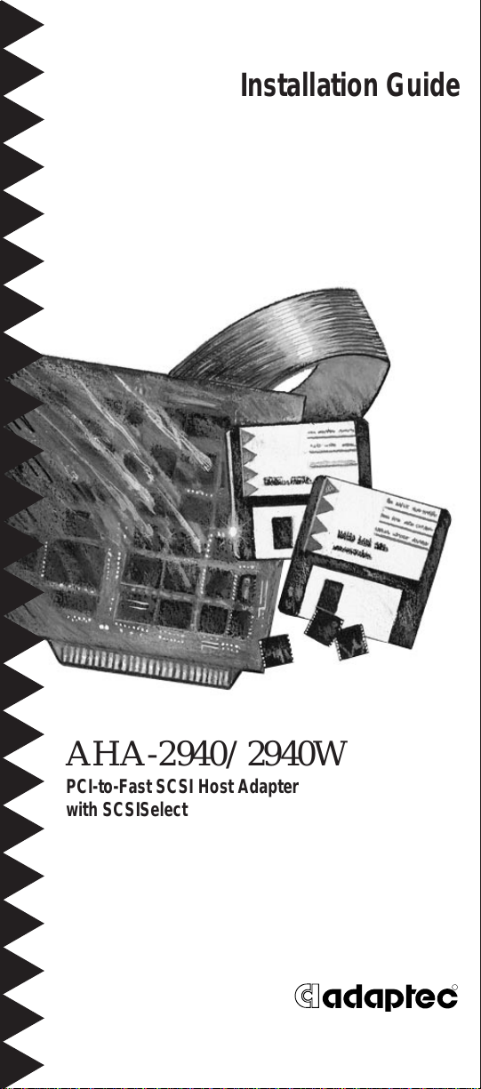
AHA-2940/2940W
PCI-to-Fast SCSI Host Adapter
with SCSISelect
R
Page 2
Introduction
Host Adapter LED
LED Connector
68-pin 16-bit
1
The Adaptec AHA®-2940 and AHA-2940W PCI-toFast SCSI host adapters prov ide a power ful mult itasking interface between you r compu ter’s PCI bus
and SCSI devices (disk dri ves , CD-RO M dri ves ,
scanners, tape backups, removable media drives,
etc.). Collectively, both host adapter s are referred to
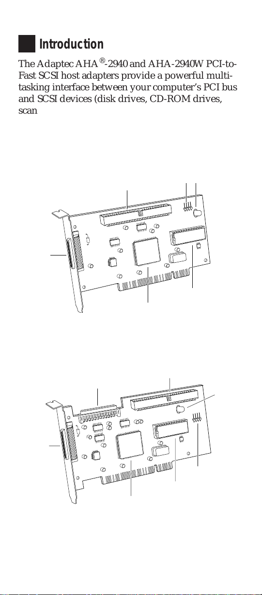
as the AHA-2940/2940W. The following figures
show the major compon ents on the AHA-2940 and
AHA-2940W.
50-pin 8-bit Internal
SCSI Connector
50-pin 8-bit
External
SCSI
Connector
Host Adapter BIOS
AIC-78xx SCSI Protocol Chip
68-pin 16-bit
External
SCSI
Connector
Adaptec AHA-2940
Internal SCSI
Connector
Adaptec AHA-2940W
50-pin 8-bit Internal SCSI Connector
AIC-78xx SCSI Protocol Chip
Host Adapter BIOS
1
Host
Adapter
LED
LED Connector
Page 3
Installing the AHA-2940/2940W
2
Follow these ins truct io ns to ins tall th e AHA-2940/
2940W:
1 Turn OFF power to the computer and peripheral
devices and disconnec t the pow er cords.
2 Remove the cover from the computer case.
3 Locate an unused 32-bit PCI expansion slot (the
slot must support Bus Master data transfers);
unscrew and remove the metal bracket that covers
the card-slot opening. (Save the screw to use when
securing the host adapter in your computer.)
PCI slots are shorter than ISA or EISA slots and
are typically white. Usually there are three PCI
slots. (One of thes e may be a shared slot int o
which you can insert either an ISA/EISA board or
a PCI board.)
4 Insert the AHA-2940/2940W in the PCI expansion
slot. Press it down firmly so that the contacts are
securely seated in the slot.
5 When the AHA-2940/2940W is firmly seated in
the expansion slot, secure the metal bracket of the
host adapter with the screw you removed in step 3.
Do not replace the computer cover or rec onnect your
computer and peripherals to their power sources y et!
SCSI Configuration Guide lin es
3
Before installin g your SCSI devices , you sho uld
understand the basic SCSI concepts described in this
section. The infor mat ion wil l help you set up your
host adapter and devices so they function proper ly.
SCSI ID Numbers
Each device attached to the AHA-2940/2940W, as
well as the AHA-2940/2940W itself, must have a
unique SCSI ID number (0 to 7 for the AHA-2940,
and 0 to 15 for the AHA-2940W).
We recommend that you leave the AHA-2940/
2940W set to its default setting of SCSI ID 7. If you
need to change the AHA-2940/2940W SCSI ID, see
2
Page 4
Configuring the Host Adapter on page 8. To change the
SCSI ID on your hard disk and other SCSI devices,
refer to the device’s documen tat ion .
The AHA-2940/2940W supports the SCSI Configured AutoMatically (SCAM) protocol, which
assigns SCSI IDs dynamically and resolves SCSI ID
conflicts automatically at bootup. If your system
includes SCSI disk drives or other devices that support SCAM, you do not need to manually assign
SCSI IDs to these devices. To disable SCA M support,
see Configuring the Host Adapter on page 8.
Most SCSI devices cur rent ly in use, how ever , do not
support SCAM. Th e SCSI IDs on these devic es mu st
be set manually. To change the SCSI IDs on these
devices, refer to the device’s docu men tat ion .
Note: If y ou plan to boot your computer from
a SCSI device attached to the AHA-2940/
2940W, set the Boot Target ID setting in the
SCSISelect utility to correspond to the SCSI
ID of the device you are booting from (see
Configuring the Host Adapter on page 8).
SCSI Terminators
To ensure reliable communication, the SCSI bus must
be properly terminated. Termination is controlled by
a set of electrical resistors, called termi nato rs. Terminators must be placed (or enabled) at the two
extreme ends of the SCSI bus. All devices that lie
between the ends must have their ter mi nato rs
removed (or disabled).
Terminating the AHA-2940
Termination on the AH A-2 940 itself is cont rolled by
software commands via the SCSISelect utility. The
default setting is Automatic, which wor ks like this:
■ If the AHA-2940 detects that a cable is connected
to either its internal or external SCSI con nect or,
then it enables its terminators (the AHA-2940 is at
the end of the SCSI bus).
3
Page 5
■ If the AHA-2940 detects that a cable is connected
to both its internal and external SCSI connector,
then it disables its terminators (the AHA-2940 lies
between the ends of the SCSI bus).
We recommend that you leave the AHA-2940 set to
its default setting of Automatic. If you want to manually enable or disable the AHA-2940 termination
settin g, s ee C onfigur ing the Host Adapter on page 8.
Terminating the AHA-2940W
Termination on the AHA-2940W itself is also controlled by software commands via the SCSISelect utility. The default setting is set to Low ON/High ON .
This means that terminat ion is enabl ed for bo th the
low and the high bytes of the 16-bit Wide SCSI bus.
The low byte controls the 8-bit SCSI; the low and
high bytes together control 16-bit Wide SCSI.
If you are using both internal connector s on the
AHA-2940W, or an internal connec tor and the external connector, you must change the termination setting from the default setting. The following table
lists the termination configurations.
AHA-2940W
Termination
Devices Connected to AHA-2940W Low High
68-pin internal connector only ON ON
68-pin external connector only ON ON
68-pin internal and 68-pin external connectors OFF OFF
50-pin internal connector only ON ON
50-pin and 68-pin internal connectors OFF ON
50-pin internal and 68-pin external connectors OFF ON
Terminating SCSI Devices
Read the device’s documentation to determine how
to enable or disable termination on your particular
SCSI device(s). On most internal SCSI devices the termination setting is controlled by a jumper or a
switch. On other intern al SCSI devices you mu st
physically remove or install resis tor module(s). On
most external SCSI devices , a terminatin g plug (a
resistor pack embedded in a small plug) is installed
or removed to control termination.
4
Page 6
Installing SCSI Devices
4
You can connect up to a total of seven internal and
external 8-bi t SCS I devices to the AHA-2940, and up
to 15 devices (seven 8-bit internal and eight Wide (16bit) internal or external SCSI devices, or 15 Wide internal and external SCSI devices) to the AHA-2940W.
Choosing SCSI Cables
The cables required to connect SCSI devices are
determined by the type of devices you are installing,
as described in the following table.
SCSI Device Type AHA-2940 AHA-2940W
8-bit Internal SCSI 50-pin internal
SCSI cable
8-bit External SCSI 50-pin high-density
external SCSI cable
16-bit Internal Wide SCSI — 68-pin internal
16-bit External Wide SCSI — 68-pin external
If you purchased your AHA-2940/2940W in an
Adaptec kit, the kit includes an intern al SCSI cable
that allows you to connect up to two internal SCSI
devices (th e AHA-2940 kit includes a 50-pin internal
SCSI cable, and the AHA-2940W kit includes a
68-pin internal SCSI cable). If you are connecting
more than two internal SCSI devic es , you must
obtain an internal SCSI cable with enough connectors to accommo d ate all of yo ur dev ices.
50-pin internal
SCSI cable
—
SCSI cable
SCSI cable
Adaptec sells high-quality internal and external SCSI
cables. If your reseller does not stock these cables,
call Adaptec direct ly at the number for ordering
Adaptec software and cables listed on page 12.
When Fast SCSI devices are connected to the host
adapter, the total length of all cables (internal and
external) must not exceed 3 meter s (9.8 ft.) to ensure
reliable operation. If no Fast SCSI devices are connected, the total length of all cables must not exceed
6 meters (19.7 ft). See your device’s documentation
to determine if it is a Fast SCSI device.
5
Page 7
Connecting Internal SCSI Devices
If you are connecting internal SCSI devices, make
sure you have an internal SCSI cable with enough
connectors to accom mod ate all of your devices .
1 Prepare each SCSI device for installation; confi g-
ure the device SCSI ID and terminators (terminate
the last internal device attac hed to the cable). For
instructions, see the device’s documentation as
well as SCSI Configuration Guidelines on page 2.
2 Install the SCSI device in your com puter. Refer to
your computer and device documentation for
instructions.
3 Plug the connector at one end of the internal SCSI
cable into the host adapter’s internal SCSI
connector.
Make sure the colored stripe on one side of the
cable is aligned with pin-1 of the host adapter ’ s
connector. Pin-1 of the connector is usually designated by a small triangle (
connector.
4 Plug the remaining connectors on the cable into
the connector s on the bac ks of the devic es.
▲), or a “1” on th e
Make sure the colored stripe on the cable is
aligned with pin-1 of the device’s connect or.
5 Connect a DC power cable (from your com-
puter’s power supply) to the power connector on
the SCSI device.
Connecting External SCSI Devices
If you are connecting external SCSI devices to your
host adapter, you must obtain an external SCSI cable
for each external device you install.
1 Prepare each SCSI device for installation; confi g-
ure the SCSI ID and attach a terminating plug into
the last external devi ce. Fo r ins truc tio ns , see the
device’s documentation as well as SCSI Configura-
tion Guidelines on page 2.
2 Plug the connector at one end of the external SCSI
cable into the host adapter’s extern al SCSI
connector.
6
Page 8
3 Plug the connector at the other end of the cable to
either one of the SCSI connectors on the external
SCSI device.
4 To connect other external SCSI devices, daisy-
chain each device to the previous device unt il all
external SCSI devices have been co nnected.
Using the LED Connector
5
(Optional) Most computers have an LED disk activity
light on the front panel. If you disconnect the cable
from the LED connector on the motherboard and
connect it to the LED connector on the host adapter,
the LED on the front panel of the computer will light
whenever there is activity on the SCSI bus.
Reassembling the Computer
6
Be sure all power switch es ar e OFF, then replace the
computer chassis cover and reconnect the power
cables to your computer and peripherals. Before
turning on your computer and peripherals , review
the follow ing section , Configuring the Host Ada pter. It
may be necessary to configure the host adapter.
Configuring the Host Adapter
7
The AHA-2940/2940W includes the onboard, menudriven SCSISele ct configuration utility, which allows
you to change host adapter settings without opening the computer or handling th e board. SCSI Sele ct
also contains SCSI disk utilities that let you low-level
format or verify the disk media of your SCSI hard
disk drives .
SCSISelect Default Settings
The AHA-2940/2940W has the default settings
shown in the table on the following page. The default
settings are appropriate for most PCI systems. If you
do not need to change any of the default settings,
there is no need to run SCSISelect. Your host ad apter
is ready for operation and you can proceed to Install-
ing Device Drivers on page 10.
7
Page 9

For situations wher e you mi ght want or need to
change the settings, see the descriptions of each setting in the user’s guide. If you need to change any of
the default settings, or if you would like to format or
verify a disk, see Starting the SCSISelect Utility on
page 9 to start the utility.
Basic Host Adapter Settings Default
Host Adapter SC SI ID 7
SCSI Parity Checking Enabled
1
Host Adapter SCSI Termination Automatic
Low ON/
High ON
Boot Device Settin gs Default
Boot Target ID 0
Boot LUN Number
3
0
SCSI Device Settings Default
Initiate Sync Negotiation Yes (Enabled)
Maximum Sync Transfer Rate 10 MBytes/sec
Enable Disconnection Yes (Enabled)
Initiate Wide Negotiation
2
Send Start Unit SCSI Comm a nd
4
Yes (Enabled)
No (Disabled)
Advanced Host Adapter Settings Default
Plug and Play SCAM Support Disabled
Host Adapter BIOS Enabled
4
4
4
Boot only
Enabled
Enabled
Disabled
Enabled
Enabled
Enabled
Support Removable Disks Under BIOS as Fixed Disks
Extended BIOS Translation for DOS Drives > 1 GByte
Display <Ctrl-A> Message During BIOS Initialization
Multiple LUN Support
BIOS Support for More Than 2 Drives
BIOS Support for Bootable CD-ROM
BIOS Support for Int 13 Extensions
1
Applies to AHA-2940 only
2
Applies to AHA-2940W only
3
Setting is valid only if Multiple LUN Support is enabled
4
Settings are valid only if host adapter BIOS is enabled.
4
4
4
4
;
2
8
Page 10

Starting the SCSISelect Utility
You can start the SCSISelect utility by pressing Ctrl-A
when the following prompt appears at boot time:
Press <Ctrl><A> for SCSISelect (TM) Utili ty!
The first menu that appears display s the optio ns
Configure/View Host Adapter Settings and SCSI
Disk Utilities.
Using SCSISelect Menus
SCSISelect uses menus to list optio ns you can sel ect.
To select an option, use the ↑ and ↓ keys to move the
cursor to the option, then press Enter.
In some cases, selecting an option displays another
menu. You can return to the previous menu at any
time by pressing Esc. To restor e the original SCSISelect
default values, press F6. To toggle the display
between color and monochrome modes, press F5 (this
feature may not work on some kinds of monitors).
Exiting SCSISelect
To exit SCSISelect, press Esc until a message prompts
you to exit (if you changed any AHA-2940/2940W
settings, you are prompted to save the changes
before you exit). At the prompt, select Yes to exit,
then press any key to reboot the computer. Any
changes you made in SCSISele ct take effect after the
computer boots.
Using the SCSI Disk Utilities
To access the SCSI disk utilities, select the SCSI Disk
Utilities option f r om the menu tha t appear s after sta rt-
ing SCSISelect. Once the option is selected, SCSISelect
immediately scans the SCSI bus and di splays a list of
all SCSI IDs and the devices assigned to each ID.
When you select a specific ID and device, a small
menu appears, displaying the options Format Disk
and Verify Disk Medi a.
■ Form at Disk—This utili ty al low s you to perfor m
a low-level format on a hard disk drive. Most
SCSI disk devices are preformatted at the factory
and do not need to be formatted again. The
Adaptec Form at Dis k utilit y is compatible w ith
the vast majority of SCSI disk drives.
9
Page 11

■ Verify Disk Media—This utility allows you to
scan the media of a hard disk drive for defects. If
the utility finds bad blocks on the media, it
prompts you to reassign them; if you select yes,
those blocks are no longer used. Y ou can press Esc
at any time to abort the utility.
8
Installing Device Drivers
Some operating systems embed (include) the
AHA-2940/2940W device driver as part of thei r installation software. These drivers work fine with your
AHA-2940/2940W; however, the most recent version
of the driver should be installed in order for your
AHA-2940/2940W to perform at its optimum level.
If you purchased your AHA-2940/2940W in a kit, the
kit includes the latest Adaptec EZ-SCSI and Adaptec
7800 Family Manager Set software.
■ Adaptec EZ-SCSI—allows you to install software
drivers for DOS/Windows and several additional
utilities. Refer to the EZ-SCSI User’s Guide.
■ Adap tec 7800 Family Manager Set—allows you
to install software drivers for NetWare, OS/2,
Windows NT, and UNIX. Refer to the 7800 Family
Manager Set User ’s Guide.
If you need to order EZ-SCSI or the 7800 Family
Manager Set, call the number for ordering Adaptec
software and cables listed on page 12.
T roubleshooting Checklist
9
If you have a problem during installation, check
these items first:
■ Hav e you ins talled the host adapter into a PCI
Rev 2.0 compliant computer?
■ Are all SCSI devices powered?
■ Are all SCSI bus cables and power cables properly
connected? Is pin 1 oriented co rrect ly?
■ Does the host adapter and all devices on the SCSI
bus have unique SCSI IDs?
10
Page 12

■ Are all devices on the SCSI bus terminated
properly?
■ Do es your sys tem CM OS set up require you to
enable PCI bus parameters? If so, see your
computer’s docum ent atio n. Ch eck that IRQ
channel assignm ent, board, and BIOS settings
have been made.
■ Did you install your host adapter in a bus master
PCI slot? Refer to your comput er’s docum ent a tion or try another slot.
Computer Will Not Boot from a SCSI Disk Drive
If both SCSI and non-SCSI disk drives are installed,
then the non-SC SI disk dr ive is always th e boot
device. If the system has only SCSI disk drives, do
the follow ing:
1 Make sure the drive type in your computer’s
CMOS setu p is set to No Drives Installed.
2 Make sure the boot hard disk SCSI ID corre-
sponds to the Boo t Target ID setting in SCSISelect
(see page 8). The SCSI ID is normally set with
jumpers or switches on the drive.
3 If this does not solve the problem, back up all data
on the SCSI hard disk and perform a low-level
format with the SCSISelect Format Disk
See the MS-DOS docum entation for inst ruct io ns
on partitioning th e disk after for m att ing.
option.
11
Page 13

Adaptec Customer Support
10
If you have questions about installing or using your Adaptec
product, check this guide first—you will find answers to most of
your questions here. If you need further assistance, please contact
us. We offer the following support and information services:
■ For technical support (answers to technical questions, informa-
tion about the Adaptec BBS, FTP and WWW Servers, and
access to the Interactive Fax system), call 800-959-SCSI (7274)
or 408-945-2550, 24 hours a day, 7 days a week. To speak with a
product support representative, call 408-934-SCSI (7274),
M–F: 6:00 a.m. to 5:00p.m., Pacific Time.
■ To order Adaptec software and SCSI cables, call 800-442-SCSI
(7274) or 408-957-SCSI (7274), M–F: 6:00 a.m. to 5:00 p.m.,
Pacific Time.
■ The Adaptec Electronic Bulletin Board Service (BBS) provides
information on software upgrades, answers to common questions, and other topics. The BBS is available 24 hours a day,
7 days a week, at 408-945-772 7 ; 12 00/2400/9600/14,400/28,800
baud, 8 data bits, 1 stop bit, no parity.
■ The Adaptec FTP and WWW Servers provide information on
software upgrades, product literature, answers to common
questions, and other topics. The FTP and WWW Servers are
available from the Internet 24 hours a day, 7 days a week, at
ftp.adaptec.com and http://www.adaptec.com.
■ The Adaptec Interactive Fax system provides answers to com-
mon questions, product literature, and current information
about Adaptec products and services. The Adaptec Interactive
Fax system is available 23 hours a day, 7 days a week. The Fax
system is out of service 1 hour each day. You can call this service directly at 408-957-7150.
■ To request additional documentation for Adaptec products,
call 800-934-2766 or 510-732-38 29, M–F: 6:00 a.m. to 5:00 p.m.,
Pacific Time.
12
Page 14

FCC Compliance Statement
NOTE: This equipment has been tested and found to comply with the limits
for a Class B digital device, pursuant to Part 15 of the FCC rules. These limits are designed to provi de reasonable protection against harmful interference in residential installations. This equipment generates, uses, and can
radiate radio frequency energy, and if not installed and used in accordance
with the instructions, may cause harmful interference to r adi o communications. However, there is no guarantee that interference will not occur in a
particular installation .
If this equipm e nt does cause interference to radio or television equipment
reception, which can be determined by turning the equipment off and on,
the user is encouraged to try to correct the interference by one or more of the
following measures:
• Reor ient or relocat e the receiving antenna
• Move the equipment away from the receiver
• Plug the equipment into an outlet on a circuit different from that to
which the receiver is powered
• If necessary, the user should consult the dealer or an experienced radio/
television technician for additional suggest ions
CAUTION: Only equipment certified to comply with Class B (computer
input/output devices, ter min als, printers, etc.) should be attached to this
equipment, and must have shielded interface cables.
Finally, any changes or modifications to the equipment by the user not
expressly approved by the grantee or manufacturer could void the user's
authority to operate such equipment.
Each host adapter is equipped with an FCC compliance label which shows
only the FCC Identification number. The full text of the associated label
follows:
This device complies with part 15 of the FCC rules. Operat ion is subject to
the following two conditions: (1) this device may not cause harmful interference and (2) this device must accept any interference received, including
interference that may cause undesired operation.
Adaptec, Inc.
691 South Milpitas Blvd.
Milpitas, CA 95035
Copyright © 1995, Adaptec, Inc. All rights reserved. Adaptec, the
Adaptec logo, AHA, EZ-SCSI, and SCSISelect are trademarks of
Adaptec, Inc. which may be registered in some jurisdictions. All
other trademarks are owned by their respective owners.
Printed in Singapore
Stock No.: 510881-00, Rev. A RQ 7/95
Information subject to change without notice.
13
 Loading...