


AHA-2740/2742
Single-Channel
AHA-2740T/2742T
TwinChannel
EISA-to-Fast SCS I Host Adapters
User’s Manual
Adaptec AHA-2740 Series User’s Manual
Stock Number: 510381-00 / Rev. C (Page A-1)
Print Spec Number: 491709-00 Rev C
Current Date: 9/1/93 ECN Date: 9/14/93

Adaptec, Inc.
691 South Milpitas Boulevard
Milpitas, CA 95035
Copyright © 199 3, Ada ptec , In c.
All rights reserved. Adaptec and the Adaptec logo
are registered trademarks of Adaptec, Inc.
Printed in Singapore
STOCK NO.: 510381-00 Rev. C LL 9/93
Information subject to change without notice.
Adaptec AHA-2740 Series User’s Manual
Stock Number: 510381-00 / Rev. C (Page A-2)
Print Spec Number: 491709-00 Rev C
Current Date: 9/1/93 ECN Date: 9/14/93

AHA-2740/2742
Single-Channel
AHA-2740T/2742T
TwinChannel
EISA-to-Fast SCS I Host Adapters
User’s Manual
▲
▲ ▲ ▲ ▲ ▲ ▲ ▲ ▲ ▲ ▲ ▲
Adaptec AHA-2740 Series User’s Manual
Stock Number: 510381-00 / Rev. C (Page 0-i)
Print Spec Number: 491709-00 Rev C
Current Date: 9/1/93 ECN Date: 9/14/93

Copyright
Copyright © 1993 Adaptec, Inc. All rights reserved. No part of this publication may
be reproduced, stored in a retrieval system, or transmitted in any form or by any
means; electronic, mechanical, photocopying, recording or otherwise, without the
prior written consent of Adaptec, Inc., 691 South Milpitas Blvd., Milpitas, CA 95035.
Trademarks
All product names mentioned below and in this manual are trademarks or registered
tradem arks o f th eir re spec tive ow ners .
Adaptec and the Adaptec logo are registered trademarks, and AHA, TwinChannel,
and PhaseEngine are trademarks of Adaptec, Inc.
AT&T is a registered trademark of American Telephone and Telegraph Company.
Bernoulli is a registered trademark of Iomega Corporation.
IBM, OS/2, AT, and Micro Channel are registered trademarks of International Busi-
ness Machines Corporation.
MS-DOS is a registered trademark of Microsoft Corporation.
NetWare is a registered trademark of Novell, Inc.
SCO is a registered trademark of the Santa Cruz Operation, Inc..
UNIX is a registered trademark and USL is a trademark of Unix Systems Laboratories.
Changes
The material in this manual is for information only and is subject to change without
notice. While reasonable efforts have been made in the preparation of this manual to
assure its accuracy, Adaptec, Inc. assumes no liability resulting from errors or omissions
in this manual, or from the use of the information contained herein.
Adaptec reserves the right to make changes in the product design without reservation
and without notification to its users.
ii
Adaptec AHA-2740 Series User’s Manual
Stock Number: 510381-00 / Rev. C (Page 0-ii)
Print Spec Number: 491709-00 Rev C
Current Date: 9/1/93 ECN Date: 9/14/93

FCC Compliance Statement
NOTE: This equipment has be en tested and foun d to comply with the limits for a
Class B digital device, pursuant to Part 15 of the FCC rules. These limits are
designed to provide reasonable protection against harmful interference in residential
installations. This equipment generates, uses, and can radiate radio frequency
energy, and if not installed and used in accordance with the instructions, may cause
harmful interference to radio communications. However, there is no guarantee that
interference will not occur in a particular installation.
If this equipment does cause interference to radio or television equipment reception,
which can be determined by turning the equipment off and on, the u ser is encouraged to try to correct the interference by one or more of the following measures:
Reorient or relocate th e receivi ng ant enna
•
Move the equipment aw ay from the rec eiver
•
Plug the equipment into an ou tlet on a circuit differen t from that to
•
which t he re cei ver is pow ere d
If necessary, th e user s hou ld cons ult the deal er or an exp eri enc ed
•
radio/television technician for additional suggestions
CAUTION: Only equipment certified to comply with Class B (computer input/output
devices, terminals, printers, etc.) should be attached to this equipment, a nd must
have shielded interface cables.
Finally, any change or modifications to the equipment by the user not expressly
approved by the grantee or manufacturer could void the user’s authority to operate
such equipment.
Each AHA-2740 Series host adapter is equipped with an FCC compliance label
which shows only the FCC identification number. The full text of the associated label
follows:
This device complies with part 15 of the FCC rules. Operation is subject to the following two conditions: (1) this device may not cause harmful interference and (2) this
device must accept any interference received, including interference that may cause
undesired operation.
Adaptec AHA-2740 Series User’s Manual
Stock Number: 510381-00 / Rev. C (Page 0-iii)
Print Spec Number: 491709-00 Rev C
Current Date: 9/1/93 ECN Date: 9/14/93
iii

Adaptec AHA-2740 Series User’s Manual
Stock Number: 510381-00 / Rev. C (Page 0-iv)
Print Spec Number: 491709-00 Rev C
Current Date: 9/1/93 ECN Date: 9/14/93

Table of Contents
Preface
Inside This Manual . . . . . . . . . . . . . . . . . . . . . . . . . . . . . . . . . xi
Con v entio n s . . . . . . . . . . . . . . . . . . . . . . . . . . . . . . . . . . . . . . xii
Advisories. . . . . . . . . . . . . . . . . . . . . . . . . . . . . . . . . . . . . xiii
1
Introduction
About This Chapter . . . . . . . . . . . . . . . . . . . . . . . . . . . . . . . . 1-1
Ove rv i ew. . . . . . . . . . . . . . . . . . . . . . . . . . . . . . . . . . . . . . . . . 1- 3
The AHA-2740 Series of Host Adapters . . . . . . . . . . . . . . . . 1-3
Features . . . . . . . . . . . . . . . . . . . . . . . . . . . . . . . . . . . . . . . . . 1-4
Fast Data Transfer Rates . . . . . . . . . . . . . . . . . . . . . . . . 1-4
Maximum Off-load ing the Host CPU. . . . . . . . . . . . . . . 1-4
Fully Disk Array Capable. . . . . . . . . . . . . . . . . . . . . . . . 1-5
Advanced Fast SCSI-2 Implementa tion. . . . . . . . . . . . . 1-5
Multiple Device and Application s Suppor t . . . . . . . . . . 1-5
Board Layout . . . . . . . . . . . . . . . . . . . . . . . . . . . . . . . . . . . . . 1-6
Default Settings. . . . . . . . . . . . . . . . . . . . . . . . . . . . . . . . . . . 1-7
The On-board Floppy Contr oller
(AHA-2742/2742T Only) . . . . . . . . . . . . . . . . . . . . . . . . 1-8
Unp ackin g an d Inspectio n. . . . . . . . . . . . . . . . . . . . . . . . . . . 1-8
Adaptec Technical Support . . . . . . . . . . . . . . . . . . . . . . . . . . 1-9
2
Getting Started
About This Chapter . . . . . . . . . . . . . . . . . . . . . . . . . . . . . . . . 2-1
Installation Overview . . . . . . . . . . . . . . . . . . . . . . . . . . . . . . 2-3
The Host Adapter and the SCSI Bus . . . . . . . . . . . . . . . . . . 2-4
Quick Installation . . . . . . . . . . . . . . . . . . . . . . . . . . . . . . . . . 2-5
Prepare Your SCSI Devic es . . . . . . . . . . . . . . . . . . . . . . 2-5
Install Your Host Adapter and Peripherals. . . . . . . . . . 2-6
Configure the Host Adapter . . . . . . . . . . . . . . . . . . . . . . 2-7
Installation. . . . . . . . . . . . . . . . . . . . . . . . . . . . . . . . . . . . . . . 2-8
Termination on the SCSI Bus. . . . . . . . . . . . . . . . . . . . . 2-9
SCSI ID Sett i n g. . . . . . . . . . . . . . . . . . . . . . . . . . . . . . . 2- 12
Board Installation . . . . . . . . . . . . . . . . . . . . . . . . . . . . . 2-13
Adaptec AHA-2740 Series User’s Manual
Stock Number: 510381-00 / Rev. C (Page 0-v)
Print Spec Number: 491709-00 Rev C
Current Date: 9/1/93 ECN Date: 9/14/93
v

AHA-2740 Series User’s Manual
SCSI Bus Activity LED Con n ecto r . . . . . . . . . . . . . . . 2-14
Con n ectin g Periphera ls . . . . . . . . . . . . . . . . . . . . . . . . 2-15
Before Re-booting Your System. . . . . . . . . . . . . . . . . . 2-23
Reassemble the System . . . . . . . . . . . . . . . . . . . . . . . . 2-23
3
Configuring the Host Adapter
About This Chapter. . . . . . . . . . . . . . . . . . . . . . . . . . . . . . . . 3-1
The EISA Configuration Utility. . . . . . . . . . . . . . . . . . . . . . 3-3
Run the EISA Configuration Utility . . . . . . . . . . . . . . . 3-4
Copy Configur ation and Ove rlay Files . . . . . . . . . . . . . 3-4
Select the Host Adapter . . . . . . . . . . . . . . . . . . . . . . . . . 3-4
Configure the Host Adapter Parameters . . . . . . . . . . . 3-5
BIOS and Device Config u ration. . . . . . . . . . . . . . . . . . 3-1 2
Exit the EISA Configuration Utility . . . . . . . . . . . . . . 3-19
Utilities . . . . . . . . . . . . . . . . . . . . . . . . . . . . . . . . . . . . . . . . 3-19
Disk Format Utility . . . . . . . . . . . . . . . . . . . . . . . . . . . 3-20
Host Adapter Diagnostic Utility . . . . . . . . . . . . . . . . . 3-21
4
Troubleshooting
About This Chapter. . . . . . . . . . . . . . . . . . . . . . . . . . . . . . . . 4-1
SCSI Troubleshooting Checklist . . . . . . . . . . . . . . . . . . . . . 4-3
Problems and Solutions . . . . . . . . . . . . . . . . . . . . . . . . . . . . 4-4
Conflicts With Other Option s. . . . . . . . . . . . . . . . . . . . . . . . 4-7
APPENDICES
A
Specifications
About This Appendix. . . . . . . . . . . . . . . . . . . . . . . . . . . . . . . A-1
Technical Information. . . . . . . . . . . . . . . . . . . . . . . . . . . . . . A-3
Product Specific ations. . . . . . . . . . . . . . . . . . . . . . . . . . . . . . A-3
Extended In dustr y- Standar d Ar chitec tur e Inter fac e . . . . . A-4
SCSI Interfac e. . . . . . . . . . . . . . . . . . . . . . . . . . . . . . . . . . . . A-4
Electrical Inte rface. . . . . . . . . . . . . . . . . . . . . . . . . . . . . A-4
Floppy Disk Interface . . . . . . . . . . . . . . . . . . . . . . . . . . . . . . A-8
Standard Electro nic and Physical Inter fac e . . . . . . . . . A-8
Con n ector . . . . . . . . . . . . . . . . . . . . . . . . . . . . . . . . . . . . A-8
vi
Adaptec AHA-2740 Series User’s Manual
Stock Number: 510381-00 / Rev. C (Page 0-vi)
Print Spec Number: 491709-00 Rev C
Current Date: 9/1/93 ECN Date: 9/14/93

B
I/O Operating Environment
About This Appendix. . . . . . . . . . . . . . . . . . . . . . . . . . . . . . . B-1
Host Adapter Support . . . . . . . . . . . . . . . . . . . . . . . . . . . . . . B-3
DOS/Win d ows . . . . . . . . . . . . . . . . . . . . . . . . . . . . . . . . . B-3
C
Optimizing Performance
About This Appendix. . . . . . . . . . . . . . . . . . . . . . . . . . . . . . . C-1
Performance Tips. . . . . . . . . . . . . . . . . . . . . . . . . . . . . . . . . . C-3
Enabling Synchronou s Negotiation . . . . . . . . . . . . . . . . C-3
Disabling the Host Adapter BIOS . . . . . . . . . . . . . . . . . C-3
Enabling SCSI Bus Parity . . . . . . . . . . . . . . . . . . . . . . . C-4
Setting Enable Disconnection. . . . . . . . . . . . . . . . . . . . . C-4
Send Start Unit Command . . . . . . . . . . . . . . . . . . . . . . . C-4
DOS/Window s Perf or manc e . . . . . . . . . . . . . . . . . . . . . . C-5
D
Table of Cont ent s
Disk Drives Over 1 Gigabyte
About This Appendix. . . . . . . . . . . . . . . . . . . . . . . . . . . . . . . D-1
Extended Translation (Using DOS 5.0) . . . . . . . . . . . . . . . . D-3
The DOS 1 Gigabyte Limit . . . . . . . . . . . . . . . . . . . . . . . . . . D-3
When to Use Extended Translation . . . . . . . . . . . . . . . . . . . D-4
With DOS Version 5 Only. . . . . . . . . . . . . . . . . . . . . . . . D-4
Drives With Mixed Partition s. . . . . . . . . . . . . . . . . . . . . D-4
Using Fdisk . . . . . . . . . . . . . . . . . . . . . . . . . . . . . . . . . . . D-4
Questions and Answers About Exten de d Translation. . . . . D-5
Glossary
About This Glossary. . . . . . . . . . . . . . . . . . . . . . . . . . Glossary-1
Glossary . . . . . . . . . . . . . . . . . . . . . . . . . . . . . . . . . . . Glossary-3
Index
. . . . . . . . . . . . . . . . . . . . . . . . . . . . . . . . . . . . . . . . . . . . . Index-1
vii
Adaptec AHA-2740 Series User’s Manual
Stock Number: 510381-00 / Rev. C (Page 0-vii)
Print Spec Number: 491709-00 Rev C
Current Date: 9/1/93 ECN Date: 9/14/93

AHA-2740 Series User’s Manual
List of Figures
Figure 1-1. Host Adapter Board Layou t . . . . . . . . . . . . . . . . 1-6
Figure 2-1. Connec tor s on the Host Adapter . . . . . . . . . . . . . 2-8
Figure 2-2. Inter n al and Ex tern al De vice s . . . . . . . . . . . . . . 2-9
Figure 2-3. Inter n al Dev ic es On ly. . . . . . . . . . . . . . . . . . . . 2-10
Figure 2-4. Exter n al Dev ic es On ly. . . . . . . . . . . . . . . . . . . . 2-10
Figure 2-5. SCSI LED Conn ector. . . . . . . . . . . . . . . . . . . . . 2-14
Figure 2-6. Connec tin g Cable to Internal Conn ector . . . . . 2-17
Figure 2-7. Connec tin g Cable to SCSI Device. . . . . . . . . . . 2-17
Figure 2-8. Connec tin g a Second In ter nal SC SI Devic e. . . 2-18
Figure 2-9. Connectin g Extern al Cable to Host Adapter. . 2-19
Figure 2-10. Connectin g External Cable to SC SI Device. . 2-19
Figure 2-11. Connec tin g Multiple Exter nal SC SI Devic es. 2-20
Figure 2-12. Connecting Floppy Cable to Host Adapter. . . 2-21
Figure 2-13. Connec tin g Floppy Cable to Floppy Driv e. . . 2-22
Figure 2-14. Connec tin g a Second Floppy Drive. . . . . . . . . 2-22
Figure 3-1. Host Adapter Parameter s. . . . . . . . . . . . . . . . . . 3-5
Figure 3-2. Selectin g Interr up t Level . . . . . . . . . . . . . . . . . . 3-6
Figure 3-3. Selectin g Bus Relea se Time . . . . . . . . . . . . . . . . 3-7
Figure 3-4. Selectin g Data FIFO Thresh old . . . . . . . . . . . . . 3-7
Figure 3-5. Selecting Host Adapter BIOS Base Addres s . . . 3-8
Figure 3-6. Selectin g Hos t Adapter SCSI ID . . . . . . . . . . . . 3-9
Figure 3-7. Selectin g SCSI Bus Parity . . . . . . . . . . . . . . . . 3-10
Figure 3-8. Selectin g SCSI Selection Timeout . . . . . . . . . . 3-11
Figure 3-9. Selectin g SCSI Bus Reset at Power-on . . . . . . 3-11
Figure 3-10. Conf igur in g SCSI Bus Termin ation. . . . . . . . 3-12
Figure 3-11. BIOS and Device Conf igur ation. . . . . . . . . . . 3-12
Figure 3-12. BIOS Con fig ur ation Selection . . . . . . . . . . . . . 3-1 3
Figure 3-13. SCSI Device Con figu ration. . . . . . . . . . . . . . . 3-15
Figure 3-14. Exiting SCSI Devic e Configur ation . . . . . . . . 3-1 9
Figure 3-15. Utility Selection. . . . . . . . . . . . . . . . . . . . . . . . 3-20
viii
Adaptec AHA-2740 Series User’s Manual
Stock Number: 510381-00 / Rev. C (Page 0-viii)
Print Spec Number: 491709-00 Rev C
Current Date: 9/1/93 ECN Date: 9/14/93

List of Tables
Table 1-1. Host Adapter Components . . . . . . . . . . . . . . . . . . 1-7
Table 1-2. Host Adapter Default Settings. . . . . . . . . . . . . . . 1-7
Table 2-1. SCSI Device and AHA Configu r ation . . . . . . . . . 2-9
Table A-1. Standard EISA Bus Electronic and
Physical Interface. . . . . . . . . . . . . . . . . . . . . . . . . . . . . . . . A-4
Table A-2. Output Signals . . . . . . . . . . . . . . . . . . . . . . . . . . A-4
Table A-3. Input Signals . . . . . . . . . . . . . . . . . . . . . . . . . . . A-5
Table A-4. Internal Connector Pin Assignmen ts . . . . . . . . A-6
Table A-5. External Connec tor Pin Assignme nts. . . . . . . . A-7
Table A-6. Output and Input Signals . . . . . . . . . . . . . . . . . A-8
Table of Cont ent s
Adaptec AHA-2740 Series User’s Manual
Stock Number: 510381-00 / Rev. C (Page 0-ix)
Print Spec Number: 491709-00 Rev C
Current Date: 9/1/93 ECN Date: 9/14/93
ix

Adaptec AHA-2740 Series User’s Manual
Stock Number: 510381-00 / Rev. C (Page 0-x)
Print Spec Number: 491709-00 Rev C
Current Date: 9/1/93 ECN Date: 9/14/93

Preface
Inside This Manual
This manual provides complete in stru ction s on how to install and
use the Adaptec AHA-2740 Series of EISA-to-Fast SCSI Host
Adapters.
Chapter 1, Introdu c tion, provid es gener al in fo rmation about the
Adaptec AHA-2740 Series of host adapters. The features, board
layout, and default settings are inclu ded. It also tells you how to
contact Adaptec Technical Support.
Chapter 2, Getting Started, has the information needed to install
the host adapter and SCSI devices.
Chapter 3, Configuring the Host Adapter, describes the EISA
Configuration utility and how it is used to configu re your host
adapter. The chapter also describes the utilities available through
the EISA Configuration utility.
Chapter 4, Trouble s h ooting, has information to assist you in
troubleshooting pro blems th at may occu r dur ing installation and
configuration.
Appendi x A, Specifications, lists technical spec ific ation s of the
host adapter and its connecto rs, which may be of use to the
advanced user or technic ian .
Appendi x B, I/O O pe ra tin g Env ir on men t , prov ides info rmation
on using your host adapter with variou s opera ting sys tems, such
as DOS/Windows. A brief discussion on Adaptec’s EZ-SCSI I/O
Operating Env ironment Softwar e is a lso inc luded.
Appendi x C, Op timizing Performan ce , has various tips on
maximizing the performan c e of your host adapter.
Appendi x D, Disk Driv e s Ove r 1 Giga byte , describes Adaptec’s
extended translation feature which allows you to bypass the DOS
1024 cylinder lim it, and supp orts disk drive s up to 8 Gigaby tes
(GBytes) in size.
Adaptec AHA-2740 Series User’s Manual
Stock Number: 510381-00 / Rev. C (Page 0-xi)
Print Spec Number: 491709-00 Rev C
Current Date: 9/1/93 ECN Date: 9/14/93
xi

AHA-2740 Series User’s Manual
The Glossary has definitions of spec ial terms used in this manu al
and in SCSI literature in general.
The In de x h elps you locate specific information qu ickly.
Conventions
The following typog raph ic c on ventions are used throu ghou t this
User’s Manual.
bold
Used for keystrokes (.. press the Enter key ..) and screen selection fields (.. select Backup Device and ..).
Helvetica
Used for operator entry that must be typed exac tly as shown
( .. device=c:\adaptec\aspidos.s ys ..) and for screen messages
(..Enter Password ..).
Helvetica Italics
Used as a place holder for text you must determine and type in
(..
enter nn for number ..). Also used for program and file names
in body text (.. the
autoexec.bat
file ..).
Italics
Used for emphasis (.. is only supported ..) and docu men t r eference
(.. refer to Chapter 2, Setting Up ..).
ALL CAPITALS
Used for acronyms, such as SCSI and CD-ROM.
Hexadecimal Numbers
Are followed by an ‘h’ , e.g., 330h.
Numbered Step Marker
The
➤ symbol marks the first in a series of numbered steps.
End Mark
The
❒ symbol marks the end of the text for each chapter.
xii
Adaptec AHA-2740 Series User’s Manual
Stock Number: 510381-00 / Rev. C (Page 0-xii)
Print Spec Number: 491709-00 Rev C
Current Date: 9/1/93 ECN Date: 9/14/93

Preface
Advisories
Advisories are quick notes that stress an importan t point or warn
of a potential hazard to the system, data, and/or the user. This
manual uses three types of advisor ies whic h are as follows:
Note
Text set off in this way presents reminder, tips, or suggestions
which may simplify the assembly an d use of the host adapter.
Caution
Failure to observe this type of advisory could result in damage
to your system, devices, and/or data.
WARNING
This type of advisory is a visual alarm. Failure to
observe this type of advisory could result in injury to
the user.
❒
Adaptec AHA-2740 Series User’s Manual
Stock Number: 510381-00 / Rev. C (Page 0-xiii)
Print Spec Number: 491709-00 Rev C
Current Date: 9/1/93 ECN Date: 9/14/93
xiii

Adaptec AHA-2740 Series User’s Manual
Stock Number: 510381-00 / Rev. C (Page 0-xiv)
Print Spec Number: 491709-00 Rev C
Current Date: 9/1/93 ECN Date: 9/14/93

Adaptec AHA-2740 Series User’s Manual
Stock Number: 510381-00 / Rev. C (Page 0-x)
Print Spec Number: 491709-00 Rev C
Current Date: 9/1/93 ECN Date: 9/14/93

1
Introduction
About This Chapter
Read this chapter to find out:
An overview of the AHA-2740 Series of EISA-to-Fast
•
SCSI host adapters
The features of the AHA-2740 Series
•
The layout of the host adapter and all its major
•
components
The default settings of the host adapter and how to
•
disable or enable the on-board floppy controller
How to get help from Adaptec Technical Suppor t
•
Adaptec AHA-2740 Series User’s Manual
Stock Number: 510381-00 / Rev. C (Page 1-1)
Print Spec Number: 491709-00 Rev C
Current Date: 9/1/93 ECN Date: 9/14/93
1-1

Adaptec AHA-2740 Series User’s Manual
Stock Number: 510381-00 / Rev. C (Page 1-2)
Print Spec Number: 491709-00 Rev C
Current Date: 9/1/93 ECN Date: 9/14/93

1
Overview
This user’s manual prov ides info rmation on how to install and
configure the AHA-2740 and AHA-2742 single-ch annel, and the
AHA-2740T and AHA-2742T TwinChannel EISA-to-Fast SCSI
host adapters in an EISA comp uter system.
The AHA-2740 and AHA-2742 support a single SCSI channel
(SCSI Channel A), while the AHA-2740T and AHA-2742T support Adaptec’s TwinCh an n el (SCSI Channel A and S CSI Chan nel
B) architecture. Procedures for all adapters are the same except
when regarding the on-board flop py controller on both the
AHA-2742 and AHA-2742T .
In this manual, the AHA-2740 and AHA-2742 are referred to
jointly as the AHA-2740/2742 host adapter; the AHA-2740T and
AHA-2742T are referred to jointly as the AHA-2740T/2742T ho st
adapter. Cumulatively, all four host adapters are referred to as
the AHA-2740 Series.
The AHA-2740 Series of Host Adapters
The AHA-2740 Series provides a high performanc e c onne ction
between the EISA (Extended Industry Standar d Architec tur e)
bus and the SCSI (Small Computer System Interface) bus. The
AHA-2740 Series is a bus master device that transfers data into
host memory at burst rates of 33 MBytes/sec. These transfers are
generally 32 bits wide, except when transfe rrin g data into 8- or
16-bit memory.
Bus mastering minimizes host CPU overhead, since the AHA2740 Series has an on-board sequencer (SCSI PhaseEngin e)
that allows it to independently manag e data transfer between
SCSI devices and the comp uter system me mor y, with ou t requiring the involvement of the CPU. This is the highest performance
type of data transfer available for the EISA bus in multi-tasking
operating systems.
1-3
Adaptec AHA-2740 Series User’s Manual
Stock Number: 510381-00 / Rev. C (Page 1-3)
Print Spec Number: 491709-00 Rev C
Current Date: 9/1/93 ECN Date: 9/14/93

AHA-2740 Series User’s Manual
The AHA-2740 Series supports only sing le-en ded SCSI devic es.
Most of the SCSI drives on the market today are of this type.
Like all EISA I/O cards, the AHA-2740 Series does not have jumpers to change various EISA configur ation options. These options
are changed via the EISA Configuration utility provided with
every EISA system; however, the AHA-2742/2742T does have a
single jumper (J4) that is used to enable or disable the on-board
floppy controller.
Features
Fast Data Transfer Rates
Up to 33 MBytes/sec on EISA bus
•
2.0 MBytes/sec asynch ro nous SCSI data rate
•
5.0 MBytes/sec synch rono us SCSI data rate
•
10.0 MBytes/sec synchrono us Fast SCSI data rate
•
Maximum Off-loading the Host CPU
On-board sequencer (SCSI PhaseEngine) automates all SCSI
•
protocol
Low SCSI processing overhe ad
•
Bus master DMA implementation
•
Task scheduling and message-based co mmunic ation
•
Programmable interrupts
•
32-, 16-, and 8-bit host bus d ata transfer
•
1-4
Adaptec AHA-2740 Series User’s Manual
Stock Number: 510381-00 / Rev. C (Page 1-4)
Print Spec Number: 491709-00 Rev C
Current Date: 9/1/93 ECN Date: 9/14/93

Fully Disk Array Capable
Able to boot from any drive on the SCSI bus
•
Background processing permits smooth error recovery
•
Extensive supp or t from leading disk array ven dor s
•
Advanced Fast SCSI-2 Implementation
Concurrent support of Fast SCSI, synchronous and
•
async h ronous devic e s
Concurrent support of both standard and Fast SCSI devices
•
Scatter/Gather operation
•
Simultaneous Target/Initiator
•
Fully multitasking/multithreading
•
Uses the superior SCSI-2 (Alternative 1) external connector
•
and standard intern al ribbon connec tor
Introduction
Tagged queuing support
•
Programmable active SCSI termination
•
Multiple LUN support
•
Parity handling in Da ta, Message, and Command phases
•
Multiple Device and Applications Support
The AHA-2740/2742 can be used to install up to seven SCSI
•
devic e s
The AHA-2740T/2742T can be used to install up to 14 SCSI
•
devic e s
The AHA-2742/2742T can be used to install up to two floppy
•
diskette drives
Adaptec AHA-2740 Series User’s Manual
Stock Number: 510381-00 / Rev. C (Page 1-5)
Print Spec Number: 491709-00 Rev C
Current Date: 9/1/93 ECN Date: 9/14/93
1-5

AHA-2740 Series User’s Manual
The AHA-2740 Series BIOS fully suppor ts the extended par ti-
•
tioning capabilities of DOS 3.3 for up to two drives and DOS
5.0 and above for up to seven drives per host adapter, eight
total
The AHA-2740 Series supports both fixed and remov able
•
media devices with capacities above 1 Gigabyte (GByte)
Managers and devic e modu le softwar e av ailable for all major
•
operating systems
Board Layout
Figure 1-1 shows the location of the major compon ent s on the
host adapter; Table 1-1 provides a description of each compon ent.
J2J1 J4 J3U2U1 U5
1-6
PIN 1
PIN 1
Figure 1-1. Host Adapter Bo ard Lay out
PIN 1
U10U9 J6J5
Adaptec AHA-2740 Series User’s Manual
Stock Number: 510381-00 / Rev. C (Page 1-6)
Print Spec Number: 491709-00 Rev C
Current Date: 9/1/93 ECN Date: 9/14/93

Introduction
Table 1-1. Host Adapte r Comp o nents
Location Description
J1 External LED Connector
J2 Floppy Connector (AHA-2742/2742T only)
J3 SCSI Channel A Internal Connec tor
J4 Floppy Enable Jumper (AHA-2 742/2742T only)
J5 SCSI Channel B Internal Connec tor
J6 SCSI Channel A External Connec tor
U1 Floppy Controller (AHA-2742/2742T only)
U2 RAM
U5 Host Adapter BIOS
U9 AIC-7770 Bus Master SCSI Chip
U10 AIC-701 Configuration Chip
(AHA-2740T/2742T only)
Default Settings
Your host adapter i s already con fig u r ed for th e ma jority of EISA
class computers. Table 1-2 lists the default settings of your host
adapter. Refer to Chapter 3, Configuring the Host Adapter for
information on changing any of the settings.
Table 1-2. Host Adapter Default Settings
Description Default Setting
Interrupt Level IRQ 11, Level
Bus Release Time 60 BCLKS
Data FIFO Threshold 100%
Host Adapter BIOS Base Address D8000h
Host Adapter SCSI ID Device ID 7
SCSI Bus Parity Check Enabled
SCSI Selection Time out 256 milli secon ds
SCSI Bus Reset at Power- on Enabled
SCSI Bus Termina tion Enabled
Extended Trans lat ion for Drives > 1 GByte Enabled
Suppor t More Than Tw o Dri ves Disabled
Support Removable Disks as Fixed Disks Boot Device Only
Adaptec AHA-2740 Series User’s Manual
Stock Number: 510381-00 / Rev. C (Page 1-7)
Print Spec Number: 491709-00 Rev C
Current Date: 9/1/93 ECN Date: 9/14/93
Sensitive
1-7

AHA-2740 Series User’s Manual
The On-board Floppy Controller (AHA-2742/2742T Only)
The on-board floppy controller on the AHA-2742/2742T is enabled
by default and is controlled by Jumper J4.
If your floppy diskette drives are alr eady runnin g under
•
another contro ller , disable the on-board flopp y controlle r
by removing the jumper shunt on Jumper J4
To use the on-board floppy controller, leave the jumper
•
shunt installed on Jumper J4 and then disable your
existing floppy controlle r; refer to your compu ter or floppy
controller user documentation
Unpacking and Inspection
Your host adapter should be undamaged when you receive it. Th e
carrier or distributor where you purc hased the host adapter is
responsible for any damage incur red durin g storag e or shipmen t.
In case of damage, return the host adapter to your distribu tor ; if
the host adapter was delivered to you directly, have the carr ier
note the damage on both the delivery receipt and the freigh t bill,
then notify the freight company representative so that the
necessary insuranc e claims can be initiated.
Caution
The host ada pter is extrem ely sensiti ve to stati c electr ici ty ; even
a mild shock can destroy a component on the board. Keep the
host adapter in its conductive wrapping until you are ready to
install it in your system. Before handling the host adapter,
always ground you rself b y touchi ng the s ystem chas sis of your
computer.
1-8
Adaptec AHA-2740 Series User’s Manual
Stock Number: 510381-00 / Rev. C (Page 1-8)
Print Spec Number: 491709-00 Rev C
Current Date: 9/1/93 ECN Date: 9/14/93

Introduction
Adaptec Technical Support
The AHA-2740 Series has been specifically developed for easy
installation and use. We hope that our manuals, and the onscreen instru ction s and help available in both the host adapter
Configuration Softwar e and Ad aptec I/O Operatin g En vironmen t
Software installation programs, are complete and clear enough to
meet your needs. If you need furthe r help, plea se contact us.
The Adaptec Electronic Bulletin Board Ser vice (BBS)
•
provides infor mation on software upg rad es, new releases,
technical adv ice , and other topics. The BBS can be
reached 24 hours a day at 408-945-7727; 1200/2 400/9 6 00
baud, 8 data bits, 1 stop bi t, no parity.
The Adaptec Technical Suppo rt Hot Lin e can be reach ed
•
at 800-959-SCSI (7274) or 408-945-2550, M-Th: 6:00 a.m.
to 5:00 p.m., F: 6:00 a.m. to 3:00 p.m., PST .
The Adaptec Technical Suppo rt FAX can be reac hed 24
•
hours a day at 408-945-6776.
❒
Adaptec software can be ordered by calling 800-442-7274,
•
M-F: 5:00 a.m. to 6:00 p.m. , PST.
Additional documentation for Adaptec products can be
•
requested by calling 800-934-2766, M-F: 5:00 a.m. to 6:00
p.m., PST, or you can write to:
Adaptec, Inc.
Literature Depar tmen t
691 South Milpitas Blvd.
Milpitas, CA 95035
1-9
Adaptec AHA-2740 Series User’s Manual
Stock Number: 510381-00 / Rev. C (Page 1-9)
Print Spec Number: 491709-00 Rev C
Current Date: 9/1/93 ECN Date: 9/14/93

Adaptec AHA-2740 Series User’s Manual
Stock Number: 510381-00 / Rev. C (Page 1-10)
Print Spec Number: 491709-00 Rev C
Current Date: 9/1/93 ECN Date: 9/14/93

2
Getting Started
About This Chapter
Read this chapter to find out:
An overview of the steps involved in installing your host
•
adapter
A brief discussion on your host adapter and the SCSI bus
•
The instructions an experienced user can use to quickly
•
install the host adapter
The instructions a user who is new to SCSI, or has lim-
•
ited experience, can use to install the host adapter and
SCSI devices
Adaptec AHA-2740 Series User’s Manual
Stock Number: 510381-00 / Rev. C (Page 2-1)
Print Spec Number: 491709-00 Rev C
Current Date: 9/1/93 ECN Date: 9/14/93
2-1

Adaptec AHA-2740 Series User’s Manual
Stock Number: 510381-00 / Rev. C (Page 2-2)
Print Spec Number: 491709-00 Rev C
Current Date: 9/1/93 ECN Date: 9/14/93

2
Installation Overview
This chapter provide s instr uction s that gu ide you thr oug h
preparing SCSI device s for installation on the SCSI bus, installing the host adapter in the EISA system, connecting the devices
to the SCSI bus, cabling and re-assembling the system.
For experien ced user s wh o are already familiar with SC SI and
SCSI installation, refer to the Qu ick In st all ati on section in this
chapter for instructions that allow you to get your host adapter
up and running quickly.
If you are new to SCSI peripherals, or if you have limited experience installing option bo ard s in your compu ter, refer to the mo re
comprehensive ins tructio ns and illustration s found in the
Installation section o f t hi s chapter.
For a brief discussion on how your host adapter wor ks with other
SCSI devices on the SCSI bus, refer to the following section The
Host Adapte r and the SCSI Bus.
Installing your host adapter involves the following:
Terminating the S C SI bus
•
Setting the SCSI ID
•
Installing the host adapter board in the EISA system
•
Connecting cables and devices
•
Reassembling the system
•
Configuring the host adapter with the EISA Con f i guration
•
utility (described in Chapter 3)
Adaptec AHA-2740 Series User’s Manual
Stock Number: 510381-00 / Rev. C (Page 2-3)
Print Spec Number: 491709-00 Rev C
Current Date: 9/1/93 ECN Date: 9/14/93
2-3

AHA-2740 Series User’s Manual
The Host Adapter and the SCSI Bus
The AHA-2740 Series acts on your computer’s behalf as the host
to your suite of SCSI devices. Each chain of SCSI periph er al
devices and their host adapter work together, and is referr ed to
as a SCSI bus. When connecting SCSI device s to the SCSI bus,
consider the following:
Each AHA-2740/2742 installed in your system can be
•
used to form a SCSI bus consisting of up to seven internal
and external SCSI device s on its single-chan n el (SCSI
Channel A).
Each AHA-2740T/2742T installed in your system can be
•
used to form two SCSI busses using its TwinCh an ne l
architectu re (SCSI Channel A and SCSI Chann el B).
SCSI Channel A can control u p to seven inter nal an d
external SCSI devices, while SCSI Chann el B can contr ol
up to seven internal SCSI devices only.
The number of host adapters installed in your system is
•
limited only by the number of available EISA slots that
support bus master functions.
2-4
As with any standard bus, the wires in a SCSI cable
•
resemble transmission lines which can generate undesirable effects such as, signal reflec tion and uneven loadin g
of the line drivers. To reduce the se effect s, the SCSI bus
must be properly termin ated. (Ter mination on the SCSI
bus is discussed in detail later in this chapter.)
To identify each SCSI device’s add ress, and to determine
•
its priority on the SCSI bus, each SC SI device (in c lud ing
the host adapter) located on the SCSI bus mus t be set to a
unique SCSI ID (0-7). (SCSI ID setting is discussed in
detail later in this chapter.)
Adaptec AHA-2740 Series User’s Manual
Stock Number: 510381-00 / Rev. C (Page 2-4)
Print Spec Number: 491709-00 Rev C
Current Date: 9/1/93 ECN Date: 9/14/93

Getting Start ed
Quick Installation
The following ins tallation procedu r es are inten de d to help exper ienced users quic kly install the AHA-2740 Series of host adapters
into an EISA computer system.
If you are new to com p uter per iph er al installation or would like
more inform atio n, ref er to the more co mpr ehen sive in str uctions
and illustrations found in the Installation section of this chapter.
Prepare Your SCSI Devices
Before you physically install the host adapter and connect the
SCSI devices, you must prepare your SCSI de vices for installation on the SCSI bus:
1 Terminate the endpoints of the SCSI bus.
➤
Identify whic h two SCSI devices (inc lu din g the host adapter)
will form the physical endpoints of your SCSI bus. These
devices at the ends of the SCSI bus must have a set of resistors called terminators either installed or enabled. All other
SCSI devices installed between the ends of the SCSI bus
must have their terminators either re mov ed or disabled.
Enabling or disabling host adapter termination is software
selectable only. The factory installed bus terminators on the
AHA-2740 Series are enabled by default.
To disable termin ation on the ho st adapter, refer to Chapter
3, Configuring the Host Adapter for instructions. Refer to the
SCSI device documen t ation for infor m ation on enabling or
disabling SCSI termination on other SCSI devices.
2 Verify that each SCSI device located on the SCSI bus is set to
a unique SCSI ID (0-7).
The default value for your host adapter is SCSI ID 7. Refer to
Chapter 3, Configuring the Ho st Adapter for instruc tion s on
changing the SCSI ID for the host adapter. Refer to the SCSI
device documentation for info rmation on changin g the SCSI
ID on other SCSI devices.
2-5
Adaptec AHA-2740 Series User’s Manual
Stock Number: 510381-00 / Rev. C (Page 2-5)
Print Spec Number: 491709-00 Rev C
Current Date: 9/1/93 ECN Date: 9/14/93

AHA-2740 Series User’s Manual
Install Your Host Adapter and Peripherals
Once the SCSI bus is properly termin ated and each SCSI devic e
is set to a uniqu e SCSI ID, you can physically install your host
adapter and SCSI devices:
WARNING
Turn OFF and disconnect power to the system and external
equipment before removing t he chassis cover or attempting any
motherboard modifications.
1 Turn power off, unplu g your computer and r emov e the c over .
➤
2 Install the host adapter in an available EISA slot which
supports bus master operations (refer to the host system
documentation for details).
3 For internal SCSI devic es, co nnec t one end of the 50-pin SC SI
ribbon cable to the internal connector on the host adapter;
connect the oth er end to the conn ec tor on the inter nal SC SI
device. Make sure to align Pin 1 of the cable with Pin 1 of the
connectors on the host adapter and intern al SCSI device .
4 To connect a second intern al SCSI device, plu g the middle con-
nector of the SCSI ribbon cable to the conne ctor on the secon d
internal SCSI device.
To connect additional intern al SCSI devices to a SCSI bus,
you will need to obtain a 50-pin SCSI ribbon cable with
enough connector s to acco mmodate all of your inter nal SC SI
devices.
5 For external SCSI dev ic es, con ne ct on e end of the 50-pin
shielded cable to the external conn ector on the host adapter;
connect the other end to one of the SCSI connectors of the
external SCSI device. Extern al cable co nnector s are keyed
and can only be plugged in one way.
To connect subsequent extern al SCSI devices, you will need
to obtain additional shielded cables to chain the devices
together.
2-6
Adaptec AHA-2740 Series User’s Manual
Stock Number: 510381-00 / Rev. C (Page 2-6)
Print Spec Number: 491709-00 Rev C
Current Date: 9/1/93 ECN Date: 9/14/93

Getting Start ed
6 If you are using the floppy controller on the AHA-2742/2742T,
connect one end of the 34-pin floppy ribbon cable to the floppy
connector on the host adapter; conn ect the othe r end to the
connector on the first floppy drive (Drive A).
To connect a second floppy driv e, plug the middle conn ector of
the floppy ribbon cable to the connector on the second flop py
drive (Drive B).
7 Reinstall your cover and reco nnect all system and perip heral
power cables.
Configure the Host Adapter
All EISA computer systems are shipped with a software prog ram
generally known as the EISA Configuration utility. Run the
utility to configure your host adapter for operation in your EISA
computer system. Chapter 3, Configuring your Host Adapter
provides a comprehensiv e description of how the utility works;
however, the basic steps inv olv ed inclu de the follow ing:
1 Run the EISA Configuration utility as instructed by the EISA
➤
system vendor.
2 Copy the
!adp7771.cfg
configuration file and
adp7770.ovl
overlay file needed to configure your host adapter with your EISA
system from the diskette that came with your host adapter to
either the bootable EISA Configuration diskette or to the
directory on your hard disk where the utility is located.
3 Select the option in the utility that allows you configure the
EISA slot in which the host adapter is installed.
4 Configure the host adapter parameters.
Adaptec AHA-2740 Series User’s Manual
Stock Number: 510381-00 / Rev. C (Page 2-7)
Print Spec Number: 491709-00 Rev C
Current Date: 9/1/93 ECN Date: 9/14/93
2-7

AHA-2740 Series User’s Manual
Installation
This section is intended primarily for users who are new to SCSI
peripherals, or have limited experience in installing an option
board in their computer system.
Note
Experienced users may want to refer to the Quick Installation
section described earlier in this chapter.
The comprehen sive in str uction s in this section guide y ou thro ugh
terminating the SCSI bus, setting the SCSI ID, installing the
host adapter, and connecting peripherals and cables.
Once the host adapter is properly installed in your EISA system,
you will have to configure it as explained in Chapter 3,
Configuring the Host Adapter.
To assist you with installation, Figure 2-1 shows the location of
all the connectors on the host adapter.
2-8
EXTERNAL LED
CONNECTOR
SCSI CHANNEL B INTERNAL CONNECTOR
(AHA-2740T/2742T ONLY)
FLOPPY CONNECTOR
(AHA-2740T/2742T ONLY)
PIN 1
PIN 1
Figure 2-1. Connectors on the Ho st Adapte r
Adaptec AHA-2740 Series User’s Manual
Stock Number: 510381-00 / Rev. C (Page 2-8)
Print Spec Number: 491709-00 Rev C
Current Date: 9/1/93 ECN Date: 9/14/93
PIN 1
SCSI CHANNEL A
INTERNAL CONNECTOR
SCSI CHANNEL A
EXTERNAL CONNECTOR

Getting Start ed
Termination on the SCSI Bus
To reduce signal reflections on the SCSI bus, the first and last physical SCSI devices on the ends of the SCSI bus must hav e a set of
resistors called terminat ors either installed or enabled. All other
SCSI devices installed between the ends of the SCSI bus must have
their terminators either removed or disabled. Improper termination
of the SCSI bus results in erratic device operation or general bu s failure. Table 2-1 describes the three possible SCSI device and Adaptec
Host Adapter (AHA) configurations.
Table 2-1. SCSI D ev ice and AH A Conf igu rati on
Devices Conne cte d To Host A dapter AHA Terminatio n
Internal and External devices (AHA in betw een ) Removed/Disabled
Internal device s only (AH A at end of cable) Installed/ Enabl ed
External device s only (AH A at end of cable) Installed/Enabled
Internal and External Device s
When both intern al and exter nal S C SI devices are conn ec ted to
the host adapter, the last external device and the last internal
device should be te rmin ated, as shown in Figur e 2-2.
INTERNAL DEVICE
TERMINATION
HOST ADAPTER
NO TERMINATION
EXTERNAL DEVICE
NO TERMINATION
INTERNAL DEVICE
NO TERMINATION
EXTERNAL DEVICE
NO TERMINATION
Figure 2-2. Internal and External Devic es
Adaptec AHA-2740 Series User’s Manual
Stock Number: 510381-00 / Rev. C (Page 2-9)
Print Spec Number: 491709-00 Rev C
Current Date: 9/1/93 ECN Date: 9/14/93
ENABLED
EXTERNAL DEVICE
TERMINATION
ENABLED
2-9

AHA-2740 Series User’s Manual
Internal Devices Only
When only internal devices are connected to the host adapter, the
last device connected to the SCSI ribbon cable and the host adapter
itself should be terminated, as shown in Figure 2-3.
INTERNAL DEVICE
TERMINATION
ENABLED
HOST ADAPTER
TERMINATION ENABLED
INTERNAL DEVICE
NO TERMINATION
Figure 2-3. Internal Devices Only
External Devices Only
When only external devices are connec ted to the host adapter,
both the last device on the external chain of dev ic es and the hos t
adapter itself should be terminated, as shown in Figure 2-4.
2-10
HOST ADAPTER
TERMINATION
ENABLED
EXTERNAL DEVICE
NO TERMINATION
EXTERNAL DEVICE
NO TERMINATION
EXTERNAL DEVICE
Figure 2-4. External Devices Only
Adaptec AHA-2740 Series User’s Manual
Stock Number: 510381-00 / Rev. C (Page 2-10)
Print Spec Number: 491709-00 Rev C
Current Date: 9/1/93 ECN Date: 9/14/93
TERMINATION
ENABLED

Getting Start ed
Terminating the Host Adapte r
The factory installed bus terminators on the host adapter are
enabled by defau l t. Host adapter termination should be di sabled
only if you attach SCSI devic es to both inter nal an d exter n al connectors, since the host adapter would then be in the middle of the
SCSI bus.
Enabling or disabling host adapter termination is software
selectable only, and is done through your computer’s EISA
Configuration utility . To disable termination on the host adapter,
refer to Chapter 3, Configurin g the Ho st Adapt e r for instructions.
Terminating Other SCSI Periphera l Devic es
Most SCSI devices use a jumper or a switch located clo se to their
SCSI connecto r(s) . On some SCSI devic es, you will hav e to phy sically remove resistor modu le(s). Refer to the manufactu r er’s doc u mentation for instructions on enabling or disablin g SCSI bus
termination on your SCSI peripheral device(s).
Note
Some drives allow for the option of supplying termination
power to their resis tor modules from the SCSI bus instead of
from the drives power suppl y. This option is acceptable since
the AHA-2740 Series of host adapters always supplies termination power on the SCSI bus.
2-11
Adaptec AHA-2740 Series User’s Manual
Stock Number: 510381-00 / Rev. C (Page 2-11)
Print Spec Number: 491709-00 Rev C
Current Date: 9/1/93 ECN Date: 9/14/93

AHA-2740 Series User’s Manual
SCSI ID Setting
Each SCSI device located on the SCSI bus must be set to a
unique SCSI ID (0-7). Th e SCSI ID serves two purposes: it
uniquely defines eac h SC SI devic e’s addr es s, and it determin e s
the device’s prio rity on the bus durin g arb itration phase. The arbitration phase determin es wh ic h device w ill own the bus when two
or more devices simultaneou sly requ e st to use it. SCSI ID 7 has
the highest priori ty, and SCSI ID 0 has the lowest. When selecting the SCSI ID, consider the following :
The default value for your host adapter is SCSI ID 7
•
You only need to change a device’s SCSI ID if it conflicts
•
with the SCSI ID of another dev ic e or anoth er host
adapter (assuming they are on the same SCSI bus)
If you are installing more than one SCSI host adapter,
•
each host adapter may be set to the same SCSI ID
(assuming they are on separ a te SCSI busses)
SCSI IDs 0 and 1 are best reserved for SC SI hard di sk
•
drive s
SCSI ID 0 is best reserved for the SCSI hard disk drive
•
that will be used as you computer’s boot device
SCSI ID 1 is best reserved for a second hard disk drive
•
SCSI ID 2 is often used for tape devices
•
Refer to Chapter 3, Configuring the Host Adapter for instructions
on changing the SCSI ID for the host adapter.
The SCSI ID on most SCSI devices is typically set with jumpers
or with sw itches on the SCSI device. Refer to the SCSI device documentation for info rmation on changin g the SCSI ID on othe r
SCSI devices.
2-12
Adaptec AHA-2740 Series User’s Manual
Stock Number: 510381-00 / Rev. C (Page 2-12)
Print Spec Number: 491709-00 Rev C
Current Date: 9/1/93 ECN Date: 9/14/93

Getting Start ed
Board Installation
To install the host adapter in your EISA system, the chassis
cover must be removed and the mother board ex posed . Al ways
refer to your EISA system documentation for ins tructio ns on
removing the cha ssis cover and add ing option boards, su ch as th e
AHA-2740 Series of host adapters.
WARNING
Turn OFF and disconnect power to the system and external
equipment before removing t he chassis cover or attempting any
motherboard modifications.
To install the AHA-2740 Series of host adapters in your EISA
computer system:
1 Remove the cover of your EISA compu ter system to expose
➤
the EISA bus slots on the motherboard.
2 Locate an unused EISA slot in your system which supports
bus master operations (refer to the host computer system documentation for details) and remove the corresponding slot
cover.
3 Carefully remove the host adapter from the antistatic bag.
Place the host adapter on top of the bag if you need to set it
down.
4 Align and insert the host adapter in the EISA slot. Secure the
host adapter in your system.
Note
EISA boards require firmer seating than typical ISA expansion
boards. Make sure the host adapter is fully seated in its slot.
2-13
Adaptec AHA-2740 Series User’s Manual
Stock Number: 510381-00 / Rev. C (Page 2-13)
Print Spec Number: 491709-00 Rev C
Current Date: 9/1/93 ECN Date: 9/14/93

AHA-2740 Series User’s Manual
SCSI Bus Activity LED Connector
Most computer systems have a disk drive activity ligh t, usually
an LED (Light Emitting Diode) on the front panel. If y ou conn ec t
your system’s LED cable to the host adapter, the LED will light
to indicate data transfer on the SCSI bus.
Note
If you conn ect you r comp uter’ s LED to the h ost adap ter , the LED
will no longer indicate non-SCSI disk activity. So yo u may not
want to use this featur e i f you are running non-SCSI disk drives.
To connect the SCSI bus LED connector:
1 Refer to your system’s docu men tation to locate and unplug
➤
the LED cable from the connector on the system board.
2 Connect the LED cable to the SCSI activity LED c onne ctor
(J1) on the host adapter as shown in Figure 2-5.
Note
On systems with a two position LED cab le, connect the LED
cable to pins 1 and 2 of the LED connector .
LED CABLE
PIN 1
LED CONNECTOR
Figure 2-5. SCSI LE D Con nec tor
2-14
Adaptec AHA-2740 Series User’s Manual
Stock Number: 510381-00 / Rev. C (Page 2-14)
Print Spec Number: 491709-00 Rev C
Current Date: 9/1/93 ECN Date: 9/14/93

Getting Start ed
Connecting Peripherals
Up to seven SCSI devices can be con nected to the internal and
external conne ctor s on the AHA-2740/2742. Up to two floppy diskette drives can be connec ted to the floppy co nnec tor on the AHA 2742/2742T. Always refer to the manufactu re r’s doc ume ntation
before connecting and installing y our SCSI device(s) and/or floppy
diskette drive(s).
Note
Only Single-End ed SCSI devices are supported by the host
adapter. Differential SCSI devices may be damaged if con-
nected to the host adapter bus. Most SCSI devices currently
produced are Single -Ended SCSI devices. Consult your SCSI
device user documentation to verify that your SCSI device is a
Single-Ended SCSI device.
SCSI Devices
SCSI devices are either internal SCSI devices or external SCSI
devices. In ter nal SC SI devic es usu ally have only a single conn ec tor and can only be cable d to the inter nal c on nector on the host
adapter. External SC SI devices usu ally have two connec tor s and
can be cabled to either the exter nal con n ector on the hos t adapter
or to the external conn ec tor of an othe r exter nal SC SI devic e.
SCSI devi c e s are cabled together in a s in gl e continuous dais y- ch a in
of devices. This chain may have no b ran ches, but must r un from
device to d evi ce in a continuous ser ies . I f your host adap ter i nclude s
both internal and external SCSI devices, the host adapter will be at
the junction between the internal and external devices.
The AHA-2740/2742 has a single-chan n el, SC SI Chan nel A, tha t
can accommodate a SCSI bus with up to seven SCSI devices connected. The AHA-2740T/2742T uses Adaptec’s TwinChannel
architecture an d has two chann els, SCSI Chann el A and SC SI
Channel B, that can each accommodate a SCSI bus with up to
seven SCSI devices connected.
SCSI Channe l A is comprised of both an inter nal an d exter n al
connector , while SCSI Chan nel B is comprised of only an inter n al
2-15
Adaptec AHA-2740 Series User’s Manual
Stock Number: 510381-00 / Rev. C (Page 2-15)
Print Spec Number: 491709-00 Rev C
Current Date: 9/1/93 ECN Date: 9/14/93

AHA-2740 Series User’s Manual
connector. To connect SCSI devices to SCSI channel A, you will
need either an intern al SCSI cable and/o r exter nal SC SI cable. To
connect SCSI devices to SCSI Chan nel B, you will need only an
internal SCSI cable.
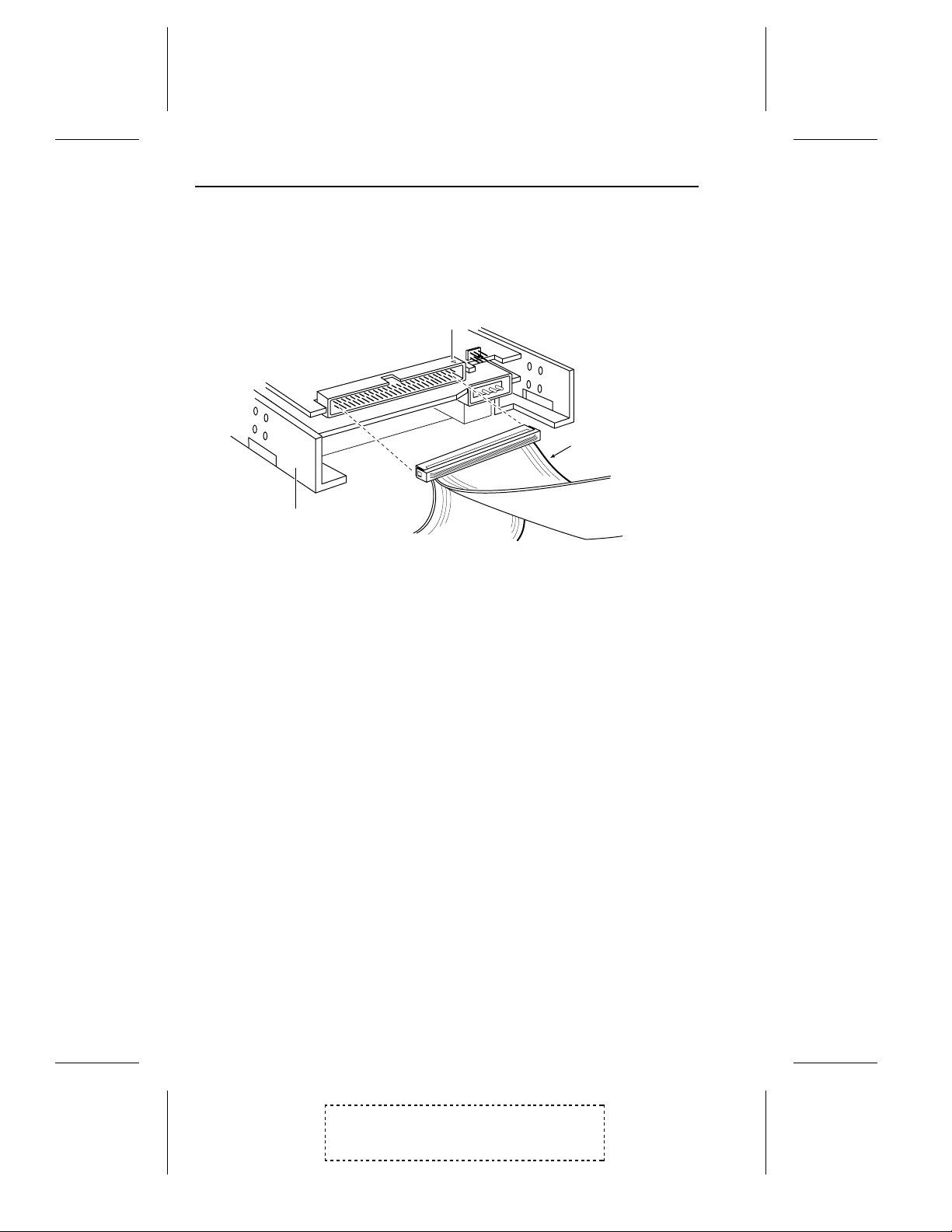
Connecting Internal SCSI Devices
The internal connec tor for your host adapter uses a 50-pin SCSI
ribbon cable with a 50-pin header intern al conn ector.
When connecting the 50-pin internal SCSI ribbon cable to both the
host adapter and to the internal SCSI device(s), make sure that Pin
1 orientation is maintained throughout the bus. Pin 1 of the SCSI
cable is designated by a colored stripe on one edge of the ribbon
cable. Pin 1 of the host adapter or S CSI device c onnector is u sually
designated by a delta or arrow symbol (▲) on the c onnector.
Note
Refer to the manufacturer’s instructio ns to install and mount
internal SCSI devices inside your computer chassis.
To connect internal SCSI devic es:
1 Connect one end of the 50-pin SCSI ribbon c able to the internal
➤
connector on the host adapter, as shown in Figure 2-6.
2-16
Adaptec AHA-2740 Series User’s Manual
Stock Number: 510381-00 / Rev. C (Page 2-16)
Print Spec Number: 491709-00 Rev C
Current Date: 9/1/93 ECN Date: 9/14/93

COLORED
STRIPE
SCSI RIBBON
CABLE
PIN 1
INTERNAL
SCSI CONNECTOR
Figure 2-6. C onne ctin g C able to Inte rnal Connector
Getting Start ed
2 Connect the other end of the 50-pin SCSI ribbon cable to the
connector on the internal SCSI device, as shown in Figure 2-7.
PIN 1
COLORED
STRIPE
INTERNAL
SCSI DEVICE
Figure 2-7. C onne ctin g Cab le to SC SI Devi ce
2-17
Adaptec AHA-2740 Series User’s Manual
Stock Number: 510381-00 / Rev. C (Page 2-17)
Print Spec Number: 491709-00 Rev C
Current Date: 9/1/93 ECN Date: 9/14/93
AHA-2740 Series User’s Manual
3 To connect a second internal SCSI devic e, plug the middle
connector of the SC SI ribbon cable to the connector on the
second internal SCSI device, as shown in Figure 2-8.
PIN 1
COLORED
STRIPE
INTERNAL
SCSI DEVICE
TO 1ST INTERNAL
SCSI DRIVE
Figure 2-8. Co nne cting a Secon d Inte rna l SCSI Device
TO HOST
ADAPTER
4 To connect three or more internal S C SI devices to a SCSI bus,
obtain a 50-pin SCSI ribbon cable with enough connectors to
accommodate all of your internal S CSI devices.
Connecting External SCSI Devi ces
The external connector for SCSI Chan nel A uses a 50-pin
shielded cable with a high-de nsity external con n ector. Extern al
cable connector s ar e keyed an d can only be plugg ed- in one way ;
Pin 1 orientation is automatic.
To connect external SCSI devices:
1 Connect one end of the external cable to the host adapter
➤
external connector, as shown in Figure 2-9.
2-18
Adaptec AHA-2740 Series User’s Manual
Stock Number: 510381-00 / Rev. C (Page 2-18)
Print Spec Number: 491709-00 Rev C
Current Date: 9/1/93 ECN Date: 9/14/93

Getting Start ed
EXTERNAL
EXTERNAL
CONNECTOR
SCSI CABLE
Figure 2-9. Co nne cting Exte rna l Cab le to H ost Ada pter
2 Connect the other end of the external cab le to either on e of the
SCSI connectors on the SCSI device, as shown in Figure 2-10.
EXTERNAL SCSI
DEVICE
EXTERNAL SCSI
CABLE
Figure 2-10 . Con nec ting E xternal C ab le to SC SI Dev ice
2-19
Adaptec AHA-2740 Series User’s Manual
Stock Number: 510381-00 / Rev. C (Page 2-19)
Print Spec Number: 491709-00 Rev C
Current Date: 9/1/93 ECN Date: 9/14/93

AHA-2740 Series User’s Manual
3 To connect subsequent external SCSI devices, obtain addi-
tional external cables and c hain eac h devic e to the previo us
device until all external S CSI devices hav e been co nnected, as
shown in Figure 2-11.
EXTERNAL SCSI
DEVICES
EXTERNAL SCSI
CABLES
Figure 2-11. Connec ting M u ltip le Extern al SCSI Devic es
Floppy Diskette Drives
Floppy diskette drives connected to the floppy connector on the
host adapter are not part of the SCSI bus; floppy diskette drives
are controlled by the non-SCSI floppy diskette controller on the
host adapter.
Connecting Floppy Diskette Drives (AHA-2742/2742T Only)
The floppy connector on the AHA-2742/2742T uses a 34-pin
floppy ribbon cable with a 34-pin header connec tor . Make sure to
maintain Pin 1 orientation a s described in prev iou s section
Connectin g Inte rn al SCSI D evic es.
Note
If you are not using the flo ppy contr oller on the AHA-2742/2742T,
be sure to disable it by removing the jumper shunt on Jumper J4.
2-20
Adaptec AHA-2740 Series User’s Manual
Stock Number: 510381-00 / Rev. C (Page 2-20)
Print Spec Number: 491709-00 Rev C
Current Date: 9/1/93 ECN Date: 9/14/93

To connect floppy diskette drives:
1 Connect one end of the 34-pin floppy ribbo n cable to the
➤
floppy connector on the host adapter, as shown in Figure 2-12.
COLORED
STRIPE
Getting Start ed
FLOPPY RIBBON
CABLE
PIN 1
FLOPPY
CONNECTOR
Figure 2-12. Connectin g Floppy C able to Hos t Adapte r
2-21
Adaptec AHA-2740 Series User’s Manual
Stock Number: 510381-00 / Rev. C (Page 2-21)
Print Spec Number: 491709-00 Rev C
Current Date: 9/1/93 ECN Date: 9/14/93

AHA-2740 Series User’s Manual
2 Connect the other end of the 34-pin floppy ribbon cable to the
connector on the first floppy drive (Drive A), as s hown in Figure
2-13.
PIN 1
FLOPPY
DISKETTE DRIVE
Figure 2-13. Connectin g Floppy C able to F loppy Drive
COLORED
STRIPE
3 To connect a second floppy drive, plug the middle connec tor of
the floppy ribbon cable to the connector on the second flop py
drive (Drive B), as shown in Figure 2-14.
PIN 1
COLORED
STRIPE
TO HOST
FLOPPY DISKETTE
DRIVE
TO 1ST FLOPPY
DRIVE
ADAPTER
Figure 2-14. Connectin g a Seco nd Floppy Drive
2-22
Adaptec AHA-2740 Series User’s Manual
Stock Number: 510381-00 / Rev. C (Page 2-22)
Print Spec Number: 491709-00 Rev C
Current Date: 9/1/93 ECN Date: 9/14/93

Getting Start ed
Before Re-booting Your System
Before re-booting your system an d c onfiguring your host adapte r,
make sure you have completed the following:
1 The SCSI bus is properly terminated.
➤
2 Each SCSI device on the SCSI bus is set to a unique SCSI ID
between 0 and 7.
3 The host adapter is firmly seated in the host computer ’s EISA
slot.
4 Internal SCSI devic es are connec ted to the host adapter with
the 50-pin SCSI ribbon cable and that proper Pin 1 orientation
is maintained.
5 External SCSI devices are properly installed and cabled.
6 If u s in g t h e o n- b o a r d f l op p y c o n t r ol l er o n t h e AHA-2742/2742T,
the floppy diskette drive is conn ected to the host adapter with
the 34-pin SCSI ribbon cable and that proper Pin 1 orientation
is maintained.
7 All system and power cables are properly connected .
Reassemble the System
Refer to your system and SCSI device documentation to replace
the system cover and connect all system and SCSI device power
cables.
❒
Adaptec AHA-2740 Series User’s Manual
Stock Number: 510381-00 / Rev. C (Page 2-23)
Print Spec Number: 491709-00 Rev C
Current Date: 9/1/93 ECN Date: 9/14/93
2-23

Adaptec AHA-2740 Series User’s Manual
Stock Number: 510381-00 / Rev. C (Page 2-24)
Print Spec Number: 491709-00 Rev C
Current Date: 9/1/93 ECN Date: 9/14/93

3
Configuring the Host Adapter
About This Chapter
Read this chapter to find out:
The step s involved in conf iguring your ho st a d ap t er with the
•
EISA Configuration utility provided with your EISA system
The host adapter parameters that can be configured
•
The options available to configure the host adapter BIOS
•
and the devices connected to the host adapter
The two utilities available in the EISA Configuration utility
•
Adaptec AHA-2740 Series User’s Manual
Stock Number: 510381-00 / Rev. C (Page 3-1)
Print Spec Number: 491709-00 Rev C
Current Date: 9/1/93 ECN Date: 9/14/93
3-1

Adaptec AHA-2740 Series User’s Manual
Stock Number: 510381-00 / Rev. C (Page 3-2)
Print Spec Number: 491709-00 Rev C
Current Date: 9/1/93 ECN Date: 9/14/93

3
The EISA Configuration Utility
All EISA machines are shipped with a bootable E ISA Configur ation
diskette that contains a software prog ram gen erally known as the
EISA Configuration utility. This utility is used to automate the
configuration of the motherboard and all option boards installed
in your EISA system.
The EISA Configuration utility must be run every time an
adapter card is physically added , removed, or moved. The utility
operates on the information provided by the
files and .
board and/or adapter card.
Always refer to the documentation provided with your EISA
system for instructions on adding and configuring adapter boards.
Depending on the EISA Config uration utility supplied w ith your
system, host adapter configuration will vary; however, the basic
steps include:
ovl
(overlay) files that accompany the EISA system
Note
.cfg
(configuration)
Run the EISA Configuration utility
•
Copy the configuration and over lay files
•
Select the host ad apter
•
Configure the host adapter parameters
•
Configure BIOS and SCSI device
•
Exit the EISA Configuration utility
•
Note
The screens displayed in this chapter may vary from the screens displayed by the EISA Configura tion utility su pplied with yo ur system.
Adaptec AHA-2740 Series User’s Manual
Stock Number: 510381-00 / Rev. C (Page 3-3)
Print Spec Number: 491709-00 Rev C
Current Date: 9/1/93 ECN Date: 9/14/93
3-3

AHA-2740 Series User’s Manual
Run the EISA Configuration Utility
Run the EISA Configuration utility as instructed by the EISA
system vendor.
Place the bootable EISA configuration diskette in an operative
drive and reset the system to boot from this diskette. If you have
the Configuration utility installed on your hard disk, reboot your
system and run the utility from your hard disk.
After booting with the host adapter installed, ignor e any error
that indicates that an unknown board has been detected in the
system.
Copy Configuration and Overlay Files
The
!adp7771.cfg
needed to configur e your ho st adapter with your EISA system are
located on the diskette that came with your host adapter.
The EISA Configuration utility typic ally allows you to select
among a number of options, includin g copyin g new configu ra tion
files. Select this option to copy the
adp7770.ovl
bootable EISA configuration diskette or to the directory on your
hard disk where the EISA Configura tion utility is located.
configuration file an d
adp7770.ovl
!adp7771.cfg
overlay file
and the
files from the host adapter diskette to either the
If the Configur a tion utility does not prov ide suc h an option , use
the DOS Copy command to copy these files.
Select the Host Adapter
Once the configuration and overlay files have been copied, choose
the option i n the E ISA C onf i g ur at i on utility that allows yo u t o configure t he EISA slot in whic h t he host adapter is in st a lle d. If necessary, scroll down the screen until you find a screen tha t lists the
host adapter and its parameters and looks similar to Figure 3-1.
3-4
Adaptec AHA-2740 Series User’s Manual
Stock Number: 510381-00 / Rev. C (Page 3-4)
Print Spec Number: 491709-00 Rev C
Current Date: 9/1/93 ECN Date: 9/14/93

Configuring the Host Adapte r
Slot 1 - Adaptec AHA-2470/AHA-2740T SCSI Host Adapter
Host Adapter Interface Definitions
Interrupt Level .........................................
Bus Release Time ...................................
Data FIFO Threshold ...............................
BIOS Definitions
Host Adapter BIOS Base Address ..........
SCSI Channel A Configuration
Host Adapter SCSI ID ...............................
SCSI Bus Parity Check ............................
SCSI Selection Timeout ...........................
SCSI Bus Reset at Power-on ...................
SCSI Bus Termination .............................
BIOS and Device configuration ...................
Utilities ........................................................
Edit=Enter <Edit Resources=F6> <Advanced=F7> <Done=F10>
IRQ 11
60 BCLKS
100%
D8000H
7
Enabled
256 milliseconds
Enabled
Enabled
Press <Enter> to configure
Press <Enter> to access
More: PgUp/PgDn
Figure 3-1. Host Adapter Para m eters
Note
If your host adapter is an AHA-2740T/2742T, a set of parameters
for SCSI Channel B is displayed and can be configured.
Configure the Host Adapter Parameters
Use the cursor keys and/or fun ction keys as instructed on the
screen’s menu to move between each parameter, or to select and
configure each parameter.
Interrupt Level
Select Interrup t Level to configure the interrupt channel (IRQ)
used by the host adapter. Figu r e 3-2 display s you r choic es. Th e
default setting is IRQ 11.
Multiple AHA-2740 Series host adapters installed in your system
can share the same IRQ; however, to increase system per formance, you may want to select a different IRQ for each host
adapter installed.
3-5
Adaptec AHA-2740 Series User’s Manual
Stock Number: 510381-00 / Rev. C (Page 3-5)
Print Spec Number: 491709-00 Rev C
Current Date: 9/1/93 ECN Date: 9/14/93

AHA-2740 Series User’s Manual
Note
The IRQ cannot be shared with ISA mode SCSI host adapters
such as the Adaptec AHA-1540 and AHA-1520 Series adapters.
If those adapters are installed in your EISA system, they must
be assigned unique IRQs.
Host Adapter Interface Definitions
Interrupt Level
( ) IRQ 11
( ) IRQ 9
( ) IRQ 10
( ) IRQ 12
( ) IRQ 14
( ) IRQ 15
Done=F10 <Edit Resources=F6> <Cancel=ESC>
Figure 3-2. Selecting Interrupt Lev el
Bus Release Time
Select Bus Release Time to configur e the amoun t of time, in
BCLKS (Bus Clocks), the host adapter will continu e to tran sfer
data after being pr e-emp te d in bus m a ster mode. Figu r e 3-3
displays your choices. The default setting is 60 BCLKS.
Normally 60 BCLKS is optimum; however, if multiple bus master
cards are installed in the system, you may want to lower the
value to free the EISA bus sooner.
3-6
Adaptec AHA-2740 Series User’s Manual
Stock Number: 510381-00 / Rev. C (Page 3-6)
Print Spec Number: 491709-00 Rev C
Current Date: 9/1/93 ECN Date: 9/14/93

Configuring the Host Adapte r
Host Adapter Interface Definitions
Bus Release Time
( ) 60 BCLKS
( ) 44 BCLKS
( ) 28 BCLKS
( ) 12 BCLKS
( ) 2 BCLKS
Done=F10 <Edit Resources=F6> <Cancel=ESC>
Figure 3-3. Selecti ng Bus R elea se Tim e
Data FIFO Threshold
Select Data FIFO Thr esh old to configure the percentage used
by the host adapter. Figure 3-4 displays your choices. The default
setting is 100%.
Normally a Data FIFO Threshold of 100% is optimum.
Host Adapter Interface Definitions
Data FIFO Threshold
( ) 100%
( ) 75%
( ) 50%
( ) 0%
Done=F10 <Edit Resources=F6> <Cancel=ESC>
Figure 3-4. Selecting Data FIFO Thr esho ld
Adaptec AHA-2740 Series User’s Manual
Stock Number: 510381-00 / Rev. C (Page 3-7)
Print Spec Number: 491709-00 Rev C
Current Date: 9/1/93 ECN Date: 9/14/93
3-7

AHA-2740 Series User’s Manual
Host Adapter BIOS Base Add ress
Select Host Adapt er B IO S Base Addr ess to configure the
BIOS base address for the host adapter, or to disable the host
adapter BIOS. Figure 3-5 displays your choic es. The default
setting is a base address of D8000h.
When choosing the base address, ver ify that there is no conflict
with other devices using the same address–often the C onfiguration utility will notify you if there is a conflic t.
Note
The BIOS must be enabled in order to boot from a SCSI fixed
disk drive attached to the host adapter.
Host Adapter BIOS Base Address
Done=F10 <Edit Resources=F6> <Cancel=ESC>
BIOS Definitions
( ) D8000H
( ) CC000H
( ) D0000H
( ) D4000H
( ) DC000H
( ) E0000H
( ) E4000H
( ) E8000H
( ) BIOS disabled
Figure 3-5. Selecting Ho st Adapte r BI OS B as e Addres s
3-8
Adaptec AHA-2740 Series User’s Manual
Stock Number: 510381-00 / Rev. C (Page 3-8)
Print Spec Number: 491709-00 Rev C
Current Date: 9/1/93 ECN Date: 9/14/93

Configuring the Host Adapte r
Host Adapte r SCSI ID
Select Host Adapt er SC SI ID to configure the SCSI ID (0-7)
setting for the host adapter. Figure 3-6 displays your choices. The
default setting is 7.
Each installed SCSI device must have a unique SCSI ID. SCSI ID
7 is normally assigned to the host adapter; SCSI IDs 0 and 1
should be reserve d for SCSI hard disk dr ive s.
If two host adapters are installed, each would have its own SCSI
bus, thus each host adapter would still be set to SCSI ID 7. Refer
to Chapter 2, Getting Started for additional information on SCSI
ID.
SCSI Channel A Configuration
Host Adapter SCSI ID
( ) 7
( ) 6
( ) 5
( ) 4
( ) 3
( ) 2
( ) 1
( ) 0
Done=F10 <Edit Resources=F6> <Cancel=ESC>
Figure 3-6. Selecting Host Adapte r SCSI ID
Adaptec AHA-2740 Series User’s Manual
Stock Number: 510381-00 / Rev. C (Page 3-9)
Print Spec Number: 491709-00 Rev C
Current Date: 9/1/93 ECN Date: 9/14/93
3-9

AHA-2740 Series User’s Manual
SCSI Bus Parity Check
Select SCSI Bu s Pa rity Check to enable or disable SCSI bus
parity checkin g on the host adapter. Fig ure 3-7 displays your
choices. The default setting is enabled.
The host adapter always generates parity when writing to the
SCSI bus. If any attached SCSI devices do not support SCSI
parity checkin g, then SCSI Bus Par ity Check should be disabled.
Most devices today , however, do support SCSI parity checking.
SCSI Channel A Configuration
SCSI Bus Parity Check
( ) Enabled
( ) Disabled
Done=F10 <Edit Resources=F6> <Cancel=ESC>
Figure 3-7. Selec ting SC SI Bus Par ity
SCSI Selec tion Timeout
Select SCSI Selection Timeout to configure the time, in milliseconds, used by the host adapter during the SCSI selection phase. Figure 3-8 displays your choices. The default setting is 256 milliseconds.
Lowering the SCSI Selection Timeout will speed up SCSI bus
scans considerably ; how ever , before lower in g this value, make
sure that all the devices on the SCSI bus can respond to the
shorter selection time.
3-10
Adaptec AHA-2740 Series User’s Manual
Stock Number: 510381-00 / Rev. C (Page 3-10)
Print Spec Number: 491709-00 Rev C
Current Date: 9/1/93 ECN Date: 9/14/93

Configuring the Host Adapte r
SCSI Channel A Configuration
SCSI Selection Timeout
( ) 256 milliseconds
( ) 128 milliseconds
( ) 64 milliseconds
( ) 32 milliseconds
Done=F10 <Edit Resources=F6> <Cancel=ESC>
Figure 3-8. Selecting SCSI Selec tion Tim eout
SCSI Bus Reset at Power-on
Select SCSI Bus Reset at Power -on to enable or disable a SCSI
bus reset generated by the host adapter during its power-on
initialization, and after a hard reset. Figure 3-9 displays your
choices. The default setting is enabled.
Normally, SCSI Bus Reset at Power-on should always be enable d.
SCSI Channel A Configuration
SCSI Bus Reset at Power-on
( ) Enabled
( ) Disabled
Done=F10 <Edit Resources=F6> <Cancel=ESC>
Figure 3-9. Selecting SCSI Bus R eset at Powe r-on
Adaptec AHA-2740 Series User’s Manual
Stock Number: 510381-00 / Rev. C (Page 3-11)
Print Spec Number: 491709-00 Rev C
Current Date: 9/1/93 ECN Date: 9/14/93
3-11

AHA-2740 Series User’s Manual
SCSI Bus Termination
Select SCSI Bus Termination to enable or disable SCSI termin ation
on the host adapter. Figure 3-10 displays your choices. The default
settin g i s enabled.
Host adapter termination should be disabled only if you attach
SCSI devices to both intern al and ex ternal co nnec tor s, sinc e the
host adapter would then be in the middle of the SCSI bus. Refer
to Chapter 2, Getting Started for informa tion on termina tion.
SCSI Channel A Configuration
SCSI Bus Termination
( ) Enabled
( ) Disabled
Done=F10 <Edit Resources=F6> <Cancel=ESC>
Figure 3-10. Confi gur ing SC SI Bus Ter m inati on
BIOS and Device Configuration
Select BIOS and Device Configuration to configure the BIOS
and SCSI device options. Figure 3-11 displays your choic es.
BIOS and Device Configuration
( ) BIOS configuration
( ) Device configuration
<ESC>
Figure 3-11. BIOS and Devic e Conf igu rati on
3-12
Adaptec AHA-2740 Series User’s Manual
Stock Number: 510381-00 / Rev. C (Page 3-12)
Print Spec Number: 491709-00 Rev C
Current Date: 9/1/93 ECN Date: 9/14/93

Configuring the Host Adapte r
BIOS Configuration
BIOS Configuration allows you to configure the host adapter
BIOS. Figure 3-12 displays you r choice s. Use the cursor keys to
move between options. To toggle values for each option, press the
Enter key.
BIOS Configuration
This configuration will affect BIOS only.
( ) Support Removable Disks as Fixed Disk .......Boot Device Only
( ) Extended Translation for Drives > 1 GByte ............... Enabled
( ) Support More than two drives .................................... Disabled
<ESC>
Figure 3-12. BIOS C onfigu rati on Sele ction
Support Removable Disks as Fixed Disk
This option allows you to configur e remov able media drive s supported by the BIOS. The default se tting is Boot Device Only. The
following choices are a vailable:
Boot Device Only – Only the removable media drive designated
as the boot device will be tr eated as a f ixed disk.
All Devices – All removable media driv es suppor ted by the
BIOS will be treated as fixed disk drives.
Disabled – No removable dr ives will be treated a s fixed
disks. Software drivers are needed for drives not controlled by
the BIOS.
Note
Support for removable drives means only that the BIOS allows
for use of a remov able drive as if it we re a f ixe d di sk driv e; it does
not mean that the disk media can be removed du r ing oper ation .
3-13
Adaptec AHA-2740 Series User’s Manual
Stock Number: 510381-00 / Rev. C (Page 3-13)
Print Spec Number: 491709-00 Rev C
Current Date: 9/1/93 ECN Date: 9/14/93

AHA-2740 Series User’s Manual
Extended Translat ion for Drives > 1 GByte
This option allows you to enable or disable extended translation
for SCSI hard disk s wi th a capac ity g re a ter than 1 G By te. Th e
default setting is enabled. Append ix D, Disk Drives Over 1
Gigabyte discusses the extended translation feature in detail.
If this option is enabled, the following translation schemes are used:
SCSI har d d i sks ≤ 1 G Byte use a translation scheme of 64
•
heads, 32 sectors per track
SCSI hard disks > 1 GByte use a translation scheme of 255
•
heads, 63 sectors per track
Note
Enabling this option for operating systems that do not need
extended translation (e.g., NetWare
®
386 and UNIX®) can
cause drive failure and/or data loss)
Support More than Two Drives
This option allows you to enable or disable BIOS support for more
than two SCSI hard disks (supported by DOS 5.0 and above). The
default setting is disabled.
SCSI Device Configuration
SCSI Device Configuration allows you to customize the configuration of each SCSI device connected on the SCSI bus. When this
option is selected, a screen similar to Figur e 3-13 is di splaye d. All
SCSI IDs are displayed on the screen even if no SCSI device is
attached; however , to configu re a specific SCSI device, you will
need to know which SCSI ID corr espon ds to tha t SCSI device.
Use the cursor keys to move between option s. To toggle v alue s for
each option, press the Enter key.
3-14
Adaptec AHA-2740 Series User’s Manual
Stock Number: 510381-00 / Rev. C (Page 3-14)
Print Spec Number: 491709-00 Rev C
Current Date: 9/1/93 ECN Date: 9/14/93

Channel A Device ID
Configuring the Host Adapte r
Configuration Setting for SCSI Devices (1x8)
#0
#1
#2
#3
#4
#5
#6
#7
Enable Disconnection
Initiate Sync Negotiation
Maximum Sync Xfer Rate
Include in BIOS Scan
Error if Device Not Found
Send Start Unit Command
OK <ESC> <DEFAULT>
yes
yes
10.0
yes
no
no
yes
yes
10.0
yes
no
no
yes
yes
10.0
yes
no
no
yes
yes
10.0
yes
no
no
yes
yes
10.0
yes
no
no
yes
yes
10.0
yes
no
no
yes
yes
10.0
yes
no
no
yes
yes
10.0
yes
no
no
Figure 3-13. SCSI Devic e Conf igu rati on
Enable Disconnection
This option is used to determine whether or not the host adapter
will allow a SCSI device to disconnect from the SCSI bus (sometimes referred to as disconnect/reconnect). This allows the host
adapter to perform other oper ation s on the SCSI bu s while the
SCSI device is temporarily disconnected.
When set to yes, the SCSI device may disconnect from the SCSI
bus. The SCSI device, howe ver, may choose not to disconnect,
even if allowed to by the host adapter (this is usually configurable
on the SCSI device). When set to no, the SCSI device will not be
allowed to disconnect from the SCSI bus. The default setting is
yes.
In general, disconn ec t should be allowed for the most efficien t
SCSI bus utilization and highest overall system performance. If
only one SCSI device is attached to the SCSI host adapter, disconnects are not required for efficien t SCSI bus utilization sinc e only
one SCSI device is using the SCSI bus. A slight performance
increase may be realized if disconnec t is not allowed in this case,
due to the decreased SCSI overhead. In multi-de vice env ironments, disconnect shou ld normally be enabled to take advantag e
of the disconnect/r econ nect featu re.
If a particular SC SI device doe s not suppor t discon nec t/r ec on nec t,
then Enable Disconne ction should be disabled (set to no). If a
particular SCSI devic e does suppo rt disco nnec t/r econ n ect, then
Enable Disconne ction should be en abled (set to yes) . Most SCSI
devices today do suppor t disconn ec t/rec onne ct.
3-15
Adaptec AHA-2740 Series User’s Manual
Stock Number: 510381-00 / Rev. C (Page 3-15)
Print Spec Number: 491709-00 Rev C
Current Date: 9/1/93 ECN Date: 9/14/93

AHA-2740 Series User’s Manual
Initiate Sync Negotiat io n
This option determines wh eth er or not the host adapter will
initiate synchro nous ne gotiation with the SCSI device.
When set to yes, the host adapter will initiate synchronous negotiation with the SCSI device. When set to no, the host adapter will
not initiate synchronous negotiation with the SCSI device. The
host adapter, however, will alw ay s respond to synchron ou s negotiation initiated from the SCSI device. The default setting is yes.
If neither the host adapter nor the SCSI peripheral negotiate for
synchronous data transfers, all data transfers will be asynchronous.
Note
Some older SCSI-1 devices may have trouble handling synchronous negotiation, which may result in erratic behavior or a
hang condition. For these device s, set Initiate Sync Negotiation
to no.
Maximum Synch Xf er Rate
This option determines the maximum synchronous transfer rate
(MBytes/sec), that the host adapter will support. The host adapter
supports rates up to the Fast SCSI maximum of 10 MBy tes/second.
The default value is 10.0 MBytes/sec . Valid values are:
3-16
10.0 MBytes/sec
•
8.0 MBytes/sec
•
6.67 MBytes/sec
•
5.7 MBytes/sec
•
5.0 MBytes/sec
•
4.4 MBytes/sec
•
4.0 MBytes/sec
•
3.6 MBytes/sec
•
Stock Number: 510381-00 / Rev. C (Page 3-16)
Print Spec Number: 491709-00 Rev C
Current Date: 9/1/93 ECN Date: 9/14/93
Adaptec AHA-2740 Series User’s Manual

Configuring the Host Adapte r
The Fast SCSI synchronous data transfer rates are 10.0, 8.0, 6.67,
and 5.7 MBytes/sec. If the host adapter is set not to negotiate for
synchronous data transfer (i.e., Initiate Sync Negotiation is set to
no), then the value selected here will be the maximu m rate that the
host adapter will accept.
In most cases, the maximum value of 10.0 MBytes/sec can be
used. If the drive is not a Fast SCSI drive and cannot support the
fast data transfer rates, it can negotiate for a slower rate (this is
standard SC SI protocol) . Howev er , if a drive cann ot acc ep t value s
greater than 5.0 MBytes/sec (the highe st standard syn chr onou s
transfer rate), then the Fast data transfer rates should not be
used for the device. Older SCSI-1 devices may not accep t the Fast
data transfer rates, which may result in erratic behavior or a
hang condition.
Include in BIOS Scan
This option determines whether or not the host adapter BIOS supports devices attached to the SCSI bus without the need for device
driver s of tw a re.
When set to yes, the host adapter BIOS control s the SCSI device.
When set to no, the host adapter BIOS will not search the SCSI
ID for devices to contro l; dev ic e driv er so ftwar e is need ed to con trol the SCSI device. The default setting is yes.
Caution
If a removable media SCSI device is controlled by the host
adapter BI OS, do not remove the media while the system is
powered-on or d ata loss could occur! The host adapter BIOS
does not support removability w hile the system is turned on . I f
removabilit y is desired while the system is powered-on, the
removable media de vice s hould be ins talled with device drivers and not the host adapter BIOS.
3-17
Adaptec AHA-2740 Series User’s Manual
Stock Number: 510381-00 / Rev. C (Page 3-17)
Print Spec Number: 491709-00 Rev C
Current Date: 9/1/93 ECN Date: 9/14/93

AHA-2740 Series User’s Manual
Error if Device Not Found
This option determines wh ether or not the host adapter BIOS
generates an error message when the BIOS is unable to find the
device du rin g boot-u p.
When set to yes, the BIOS checks the SCSI ID for a SCSI device;
if none is found, an error message is displayed du ring boot-up similar to the following:
Channel A, Target #1 – Devi ce Not Found
When set to no, the BIOS does not attempt to display en error
message if the SCSI device is not found. The default setting is no.
Send Start Unit Command
This option, which is suppor ted by some SCSI devic es, determines whether or not the SCSI Start Unit Command (SCSI command 1B) is sent to the SCSI device (most devices do not require
this). The Start Unit Command reduces the load on your computer’s power supply by allowing the host adapter to power-up SCSI
devices one-at-a-time when you boot your system. Otherw ise, the
devices will all power-up at the same time.
When set to yes, the SCSI Start Unit Command is sent to the
SCSI device dur ing boot-up. When set to no, the SCSI device will
power-up in its normal fashion. The default settin g is no.
If this option is selected for more than one SCSI device, the SCSI
device with the lowes t SCSI ID will be sent the SCSI Start Unit
Command first. When the firs t device is ready and respon ds to
the host adapter, the next highest SCSI ID with a setting of yes is
sent the SCSI Start Unit Command. This proce ss continues until
all supported devices respon d to the host adapter.
Note
If many drives are set to yes for the SCSI Start Unit Command,
system boot time will vary depending on how long each drive
takes to spin-up.
3-18
Adaptec AHA-2740 Series User’s Manual
Stock Number: 510381-00 / Rev. C (Page 3-18)
Print Spec Number: 491709-00 Rev C
Current Date: 9/1/93 ECN Date: 9/14/93
Configuring the Host Adapte r
Exit SCSI Device Configuration
When configu ra tion of SCSI devices i s complete, press Esc to exit
SCSI device configuration ; you will be prompted to either save or
abandon device configu ration s, as shown in Figure 3-14.
Save/Abandon device configuration
( ) Save device configurations
( ) Abandon device configurations
<ESC>
Figure 3-14. Exiting SC SI D evi ce Con fig ura tion
Exit the EISA Configuration Utility
Once the host adapter and SCSI devices are proper ly config ur ed,
save and exit the EISA Configuration utility as instructe d on the
screen’s menu. The following section, Utilities, descr ibes the two
utilities available in the EISA Configuration utility.
Utilities
Select Utilities from the EISA Configuration utility to access the
two SCSI utilities that are available with your host adapter, a s
shown in Figure 3-15.
Adaptec AHA-2740 Series User’s Manual
Stock Number: 510381-00 / Rev. C (Page 3-19)
Print Spec Number: 491709-00 Rev C
Current Date: 9/1/93 ECN Date: 9/14/93
3-19

AHA-2740 Series User’s Manual
AIC-7770 Utility Selection Options
( ) Disk Format Utility
( ) Host Adapter Diagnostic Utility
<ESC>
Figure 3-15. Utility Selection
Disk Format Utility
This utility allows you to low-lev el for mat you r SCSI disk and/ or
verify disk media for defects.
Note
When migr ating hard disk drives and/or rem o va ble media driv e s
from ot her manufacturer s host adapters, the disk format utility
should be run to low-level format your drive.
Disk Format
Your fixed disk media must be low-level formatted befor e you can
use your opera ting sys tem’s par titionin g and file per par ation
commands, such as MS-DOS
fdisk
and
format
.
Most SCSI disk devices are pre-formatted, and do not need
re-formatting. The Adaptec low-lev el for matting utility is
compatible with the vast majority of today’s SCSI disk drives.
Caution
All dat a o n the drive wi ll be l ost when p erforming a l ow-level format. Be su re to bac k up your d ata b efo re p erf ormi ng th is op erat ion.
3-20
Adaptec AHA-2740 Series User’s Manual
Stock Number: 510381-00 / Rev. C (Page 3-20)
Print Spec Number: 491709-00 Rev C
Current Date: 9/1/93 ECN Date: 9/14/93

Disk Verify
Configuring the Host Adapte r
Once your SCSI disk is low-level for ma tted,
disk verify
scans the
disk’s media for defec ts. If bad block s are fou nd, you ar e
prompted to reassign them.
Host Adapter Diagnostic Utility
This utility runs a diagnostic on your host adapter by doing DMA
transfers between the SCSI host adapter and system memory.
This test will run indefinitely until Esc is pressed.
❒
Adaptec AHA-2740 Series User’s Manual
Stock Number: 510381-00 / Rev. C (Page 3-21)
Print Spec Number: 491709-00 Rev C
Current Date: 9/1/93 ECN Date: 9/14/93
3-21

Adaptec AHA-2740 Series User’s Manual
Stock Number: 510381-00 / Rev. C (Page 3-22)
Print Spec Number: 491709-00 Rev C
Current Date: 9/1/93 ECN Date: 9/14/93

4
Troubleshooting
About This Chapter
Read this chapter to find out:
How to use the troubleshooting checklist to diagn ose pro b-
•
lems that may occur when you install a host adapter in
your sys tem
Problems you may encounter and how to fix them
•
How to resolve conflic ts with other options
•
Adaptec AHA-2740 Series User’s Manual
Stock Number: 510381-00 / Rev. C (Page 4-1)
Print Spec Number: 491709-00 Rev C
Current Date: 9/1/93 ECN Date: 9/14/93
4-1

Adaptec AHA-2740 Series User’s Manual
Stock Number: 510381-00 / Rev. C (Page 4-2)
Print Spec Number: 491709-00 Rev C
Current Date: 9/1/93 ECN Date: 9/14/93

4
SCSI Troubleshooting Checklist
The AHA-2740 Series has been extensively tested for compatibility with popular SCSI periph er al dev ice s acro ss variou s oper ating
systems. Most problems that might occur during installation can
be traced to errors in prepar in g devic es on the SCSI bus.
The following suggestions should help you to solve any problems
that you may encounter. If you need additional help in getting the
host adapter running pr oper ly , in formation on contac ting
Adaptec Technical Supp ort is included in Chapter 1, Introduction.
If a problem occurs during installation, check these items first:
1 Be sure all SCSI peripheral devices are connec ted to power.
➤
Connect internal periph er als to your compute r’s power supply; plug extern al perip heral pow er cable s into a grounded
line power outlet. Follow the instru ctions in the hardw are
documen ta tion.
2 Be sure all cables are properly connected. Check both power
and SCSI interface cables. See Inst alla tio n in Chapter 2.
3 Be sure the SCSI devices and host adapter on each SCSI bus
are each set to differen t SCSI ID s. See SC S I I D Se tt in g in
Chapter 2.
4 Check SCSI bus termination. The ends of the bus must be
terminated. See Termina tion on the SCSI Bus in Chapter 2.
5 If you have installed more than one SCSI host adapter make
sure that each host adapter is set to a separate BIOS address,
or disable the BIOS on all but one of the host adapters. See
Configure the Host Adapter Parameters in Chapter 3.
If your problem is still not resolved, contin ue with the next
section.
Adaptec AHA-2740 Series User’s Manual
Stock Number: 510381-00 / Rev. C (Page 4-3)
Print Spec Number: 491709-00 Rev C
Current Date: 9/1/93 ECN Date: 9/14/93
4-3

AHA-2740 Series User’s Manual
Problems and Solutions
The screen i s di ffic ul t to read when I run the EI SA Confi g u rat ion utility .
Try pressing F5 to toggle the display between color and monochrome modes. Thi s may enab le you to read the scr e en more easily.
I installed the hos t adapte r, and my com pu ter w ill not boot from th e
SCSI disk drive.
If both SCSI and non-SCSI disk drives are installed, then the nonSCSI disk drive is always the boo t devic e. If your system ha s only
SCSI disk drives:
1 Make sure your compu ter system’ s CMOS
➤
setup
is set to No
Drives Installed, as is required for SCSI host adapters.
2 Try setting the SC SI boo t drive to SCSI ID 0. Th i s is nor -
mally done by changing jumper s or switch es on the drive. On
each SCSI bus, SCSI devices must be set to a unique SCSI
ID, which ran ge fro m 0 to 7. See SCSI ID Setting in Chapter
2.
3 Try enabling Include in BIOS Scan in the BI OS and SCSI
Device Configuration option. See Configure BIOS and
SCSI Device in Chapter 3.
4 Make sure the SCSI bus is properly termin ated. See
Terminat ion on the SCSI Bus in Chapter 2.
5 You may need to low-level for mat the SCSI hard drive. If so,
first back up all data on the disk, then run the
format
accessible through the EISA Config uration utility . See
Utilitie s in Chapter 3.
Similar formatting utilities for removable media devic es are
included in the Adaptec EZ-SCSI software package for the
DOS/Windows environment. Refer to Appendix B, I/O
Operating Environm ent. These utilities are also available
from the Adaptec BBS.
utility
4-4
Adaptec AHA-2740 Series User’s Manual
Stock Number: 510381-00 / Rev. C (Page 4-4)
Print Spec Number: 491709-00 Rev C
Current Date: 9/1/93 ECN Date: 9/14/93

Troubleshooting
When I tried to use the
Unexpected SCSI Comma nd Fai lur e pop-up b o x with a lot of error
information. Wha t does this mean?
This probably means that the utility encountered a problem with
the disk device or the media and ther efor e cannot run. Th e
following information appears in the pop-up win dow :
SCSI target ID of the device
•
SCSI CDB Sent (e.g., 2F 00 00 00 00 00 00 08 00 00)
•
Host Adapter Status (e.g., 11h - Selection timeout)
•
Target Status (e.g., 00h - Good status)
•
Sense Key (e.g., 06h - Unit attention)
•
Additional Sense Code
•
Additional Sense Code Qualifier
•
You can probably determin e from the Sense Ke y information both
the cause of the problem and its solution. Here are some of the
more common Sense Key values and their meanings:
format/verify
utilit y on a disk device, I go t an
02h - Not ready
The media is not ready to format. Be sure that media is
inserted in the drive and that the media is spun-up .
03h - Medium error
The disk media may be defective. If it is a removable media
drive, try using a different media. If it is a fixed disk drive,
the disk may be physically damaged.
04h - Hardware error
The disk drive may be defective . Con sult the hardw ar e
documentation and contact the manufacturer.
05h - Illegal request
The Adaptec formatting utility does not support a low-level
format of this device. The device may already be low-level
formatted by the manufacturer . (This error rarely occur s.)
Adaptec AHA-2740 Series User’s Manual
Stock Number: 510381-00 / Rev. C (Page 4-5)
Print Spec Number: 491709-00 Rev C
Current Date: 9/1/93 ECN Date: 9/14/93
4-5

AHA-2740 Series User’s Manual
06h - Data protect
The removable media may be write-pr otec ted. Remov e write
protection and run the utility again.
The Additional Sense Code field provides more inf orm ation about
the error. The meaning of these codes may be li sted in your
hardware man ual.
My computer locks up wh e n I press Esc to exit the EISA Confi guratio n
utility .
If this happens, tur n your mach ine off and then on to reboot. Any
settings you changed before you tried to exit the program have
been registered in th e EEPROM and will not be lo st.
One of the SCSI devic es on m y system does not allow term i nat ion to
be disabled. How can I attach it to the SCSI bus ?
You might be able to attach this device on the end of the SCSI
bus so you do not need to disable termina tion on it. If thi s is not
possible, contact the manufacturer about possible work-aro unds.
I installed my host adapter board at IRQ12, and it does not work
properly. What is wron g?
Another devic e such as a mouse may be using IRQ12. Ch ang e the
adapter board’s IRQ to the default value (11) or to some oth er
value. See Configure the Host Adapter Parameters in Chapter 3.
When I insta ll m y host adapter it either does not get autom at i cal l y
added by my EI S A Co nfig u rat i on ut ili ty , or an error is repo rted by t h e
motherboar d as not being a va lid board , even after runni ng the EISA
Configuration utility.
Verify that you are using the correct
.cfg
file and
.ovl
file for the
host adapter. Also, other EISA boards and their position on the
bus could be causing the board to be mis-iden tified.
4-6
Adaptec AHA-2740 Series User’s Manual
Stock Number: 510381-00 / Rev. C (Page 4-6)
Print Spec Number: 491709-00 Rev C
Current Date: 9/1/93 ECN Date: 9/14/93

Troubleshooting
Conflicts With Other Options
You will encounter problem s if your host adapter and peripher al
devices use overlappin g exten ded BIOS and I/O addresses. To
correct this problem:
1 Change the IRQ settings with the EISA Configuration utility.
➤
2 Use the EISA Configuration utility to view BIOS addre sses
for the host adapter and, if necessary, change them.
❒
Adaptec AHA-2740 Series User’s Manual
Stock Number: 510381-00 / Rev. C (Page 4-7)
Print Spec Number: 491709-00 Rev C
Current Date: 9/1/93 ECN Date: 9/14/93
4-7

Adaptec AHA-2740 Series User’s Manual
Stock Number: 510381-00 / Rev. C (Page 4-8)
Print Spec Number: 491709-00 Rev C
Current Date: 9/1/93 ECN Date: 9/14/93

A
Specifications
About This Appendix
Read this appendix to find out:
Technical specific ation s of the AHA-2740 Series host
•
adapter, EISA interface, SCSI interface, and floppy disk
interfac e
Pin assignments for the inter nal and ex ternal SCSI
•
connectors
Adaptec AHA-2740 Series User’s Manual
Stock Number: 510381-00 / Rev. C (Page A-1)
Print Spec Number: 491709-00 Rev C
Current Date: 9/1/93 ECN Date: 9/14/93
A-1

Adaptec AHA-2740 Series User’s Manual
Stock Number: 510381-00 / Rev. C (Page A-2)
Print Spec Number: 491709-00 Rev C
Current Date: 9/1/93 ECN Date: 9/14/93

A
Technical Inform ation
The basic technical specifications of the host adapter are described
below. If you need more detailed information, contact Adaptec’s
Literature Department at the address or phone numbers listed in
Chapter 1, Introduction.
Product Specif icatio ns
Physical Dimensions
Length: 7.0 inches
Width: 0.625 inches
Height: 5.0 inches
Standard EISA-compatible form fac tor
Power Requirement s
+5.0 +/- 0.25 Volts at 2.0 Amps maximum
Environmental Requirements
Temperature: 0-55
Adaptec AHA-2740 Series User’s Manual
Stock Number: 510381-00 / Rev. C (Page A-3)
Print Spec Number: 491709-00 Rev C
Current Date: 9/1/93 ECN Date: 9/14/93
o
C (operating or storage)
A-3

AHA-2740 Series User’s Manual
Extended Industry-Standard Architecture
Interface
Table A-1. Standard EI SA Bus E lectr onic and Phy sica l Inter fa ce
Driver Output Signals
V
OL
I
OL
V
OH
I
OH
Receiver Input Sign als
V
IL
V
IH
0 volts minimum 0.4 volts maxim um
24 mA
2.4 volts minimu m 5.25 volts maxim um
8 mA
0.8 volts maximum
2.0 volts minimu m
SCSI Interface
Electrical Interface
These are the specifications listed in ANSI X3.131-1986 for
single-ended oper ation .
Output Signals
All signals use open collector or three-s tate driver s. Each sign al
driven by a SCSI device has the following output char ac teristic s
when measured at the SCSI device’s connector :
Table A-2. Output Signals
Signal Definition Characteristics
V
OL
V
OH
Low-level out put voltage 0.0 to 0.5 volts DC at 48 mA
sinking (signal assertion)
High-level output voltage 2.5 to 5.25 volts DC (signal
negation)
A-4
Adaptec AHA-2740 Series User’s Manual
Stock Number: 510381-00 / Rev. C (Page A-4)
Print Spec Number: 491709-00 Rev C
Current Date: 9/1/93 ECN Date: 9/14/93

Specifications
Input Signals
SCSI inputs meet the following elec trical ch ar acter istics on each
signal, inc lud ing both r ec eiv er s an d p a ssive dr ivers:
Table A-3. Input Signals
Signal Definition Characteristics
V
IL
V
IH
I
IL
I
IH
Low-level input voltage 0.0 to 0.8 volts DC (signal true)
High-level input volt age 2.0 to 5.25 volts DC (sign al fa ls e)
Low-level input cur re nt -0.4 to 0.0 mA at V1=0.5 volts DC
High-level input cur re nt 0.0 to 0.1 mA at V1=2.7 volts DC
Minimum in put hyster esis = 0.2 volts DC.
Maximum inp ut capaci tan ce = 25 pF (measured at the device conne ct or
closest to the stub, if any, within the devic e).
Internal SCSI Connector
The internal SCSI connector must be an unshrouded 50-pin
header, compatible with unshielded Altern ative 1 connec tor , as
specified in ANSI X3.131-1986. Table A-4 lists the pin assignment s f or the in te rn a l co nn ec t or .
Adaptec AHA-2740 Series User’s Manual
Stock Number: 510381-00 / Rev. C (Page A-5)
Print Spec Number: 491709-00 Rev C
Current Date: 9/1/93 ECN Date: 9/14/93
A-5

AHA-2740 Series User’s Manual
Table A-4 . Inte rna l Con nec tor P in As sign m ents
Pin Si gnal N ame Pin Sig nal Nam e
1 Ground 2 -DB(0)
3 Ground 4 -DB(1)
5 Ground 6 -DB(2)
7 Ground 8 -DB(3)
9 Ground 10 -DB(4)
11 G r o un d 12 -D B(5)
13 G r o un d 14 -D B(6)
15 G r o un d 16 -D B(7)
17 Gr oun d 18 -DB(P)
19 Gr oun d 20 Ground
21 Gr oun d 22 Ground
23 Gr oun d 24 Ground
25 Open 26 Term Power (Fused)
27 Ground 28 Ground
29 Ground 30 Ground
31 Ground 32 -ATN
33 Ground 34 Ground
35 Ground 36 -BSY
37 Ground 38 -ACK
39 Ground 40 -RST
41 Ground 42 -MSG
43 Ground 44 -SEL
45 Ground 46 -C/D
47 Ground 48 -REQ
49 Ground 50 -I/O
A-6
Adaptec AHA-2740 Series User’s Manual
Stock Number: 510381-00 / Rev. C (Page A-6)
Print Spec Number: 491709-00 Rev C
Current Date: 9/1/93 ECN Date: 9/14/93

Specifications
External SCSI Connect or
The external SCSI connector must be a shielded 50-pin high density (Alternative 1) connector, as specified in proposed ANSI
standard X3T9.2/86-109 Rev i sion 10h, Section 4, Figure 5. Table
A-5 lists the pin assignments for the external con nec tor.
Table A-5. Exter nal Conne ctor Pin Assi gnm ents
Pin Si gnal N ame Pin Sig nal Nam e
1 Ground 26 -DB(0)
2 Ground 27 -DB(1)
3 Ground 28 -DB(2)
4 Ground 29 -DB(3)
5 Ground 30 -DB(4)
6 Ground 31 -DB(5)
7 Ground 32 -DB(6)
8 Ground 33 -DB(7)
9 Ground 34 -DB(P)
10 Ground 35 Ground
11 Ground 36 Ground
12 Ground 37 Reserved
13 Open 38 Term Power (Fused)
14 Ground 39 Reserved
15 Ground 40 Ground
16 Ground 41 -ATN
17 Ground 42 Ground
18 Ground 43 -BSY
19 Ground 44 -ACK
20 Ground 45 -RST
21 Ground 46 -MSG
22 Ground 47 -SEL
23 Ground 48 -C/D
24 Ground 49 -REQ
25 Ground 50 -I/O
Adaptec AHA-2740 Series User’s Manual
Stock Number: 510381-00 / Rev. C (Page A-7)
Print Spec Number: 491709-00 Rev C
Current Date: 9/1/93 ECN Date: 9/14/93
A-7

AHA-2740 Series User’s Manual
Floppy Disk Interface
Standard Electronic and Physical Interface
Table A-6. Output and Input Sign als
Driver Output Signals
V
OL
V
OH
I
OL
I
OH
Receiver Input Sign als
V
T-
V
T+
Tied to +5 volt supply through 150 ohm resist ors. Schm itt Trigger wit h
0.8-volt hys teres is .
Connector
0 volts minimum 0.5 volts maxim um
Open collector 5.25 volts maximum
60 mA
0.1 mA
1.0 volts maximum
1.4 volts minimu m
The floppy disk interface connec tor should be an unshr ouded
34-pin header.
❒
A-8
Adaptec AHA-2740 Series User’s Manual
Stock Number: 510381-00 / Rev. C (Page A-8)
Print Spec Number: 491709-00 Rev C
Current Date: 9/1/93 ECN Date: 9/14/93

B
I/O Operating Environment
About This Appendix
Read this appendix to find out:
If embedded support for your host adapter is available
•
with your operatin g system
Whether or not you need additional softw are for you r host
•
adapter in the DOS/Windows environmen t
Information on Adaptec’s EZ-SCSI I/O Operating
•
Environme nt Softwar e that makes driver installation
easier than ever before
Adaptec AHA-2740 Series User’s Manual
Stock Number: 510381-00 / Rev. C ( Page B-1)
Print Spec Number: 491709-00 Rev C
Current Date: 9/1/93 ECN Date: 9/14/93
B-1

Adaptec AHA-2740 Series User’s Manual
Stock Number: 510381-00 / Rev. C (Page B-2)
Print Spec Number: 491709-00 Rev C
Current Date: 9/1/93 ECN Date: 9/14/93

B
Host Adapter Support
You may not need to install additional environment softwar e in
order to use your host adapter. Adaptec is working with major
operating system supplier s to provide embedd ed supp or t in their
operating systems. Please contact Adaptec or your operatin g
system vendor for information on the current schedu le for I/O
Operating Env ironmen t Software support.
Note
Until embedded support is provided for your particular operating system, host adapter drivers for the AHA-2740 Series may
be availabl e from Adaptec. To order Adaptec software, call the
number for ordering Adaptec software listed in the Adaptec
Techn ic al Su p po rt section found in Chapter 1, Introduction.
DOS/Windows
Under MS-DOS® 5.0 or higher, up to seven SCSI hard disk drives
per host adapter (eight total) can be connected without additional
software (older versions of DOS support up to two hard disk
drives). Additional so ftwar e is requir ed if you desir e to do any of
the following:
Support more than two fix ed disk driv es un der version s of
•
DOS prior to MS-DOS 5.0
Support more than eight fix ed disk dr ive s (seven per host
•
adapter) under MS-DOS 5.0 or higher
Remove or switch remov able media (for example,
•
Bernoull i
Support CD-ROM drives
•
Support devic es other than CD- ROM dr ives and disk
•
drives–for example: SCSI tape drives, scanners, plotters,
or worm dr ives
Adaptec AHA-2740 Series User’s Manual
Stock Number: 510381-00 / Rev. C (Page B-3)
Print Spec Number: 491709-00 Rev C
Current Date: 9/1/93 ECN Date: 9/14/93
®
cartridges) while y ou r compu ter is running
B-3

AHA-2740 Series User’s Manual
Adaptec EZ-SCSI
If you are running MS-D OS or MS-D O S with Win dow s, Adaptec
EZ-SCSI I/O Operating Environment Software makes driver
installation easier than ever before. Adaptec EZ-SCSI is a
menu-driven software package that configures your operating
environme nt automatically .
Adaptec EZ-SCSI ha s a number of utility prog r a ms including
afdisk
and
scsifmt
, which are used to format and partition SCSI
disk devices. Adaptec EZ- SCSI also inc lu des an A SPI device
driver called
and the
aspicd
aspidisk
that supports most models of CD-ROM drives
device driver, which supports up to 24 fixed- disk
devices.
To install support for SCSI devices other than fixed disk devices
and CD-ROM driv es, chec k the hard war e doc umen t atio n for
those devices. If the device requires ASPI support, you first need
to run Adaptec EZ-SCSI to install an ASPI manager, and then
install any other software provided with the device. If the device
is designed to interface dir ec tly with the host adapter, the n no
ASPI manager is require d. Refer to the Adaptec EZ-SCSI User’s
Manual for instructions on installing and running Adaptec
EZ-SCSI.
B-4
❒
Adaptec AHA-2740 Series User’s Manual
Stock Number: 510381-00 / Rev. C (Page B-4)
Print Spec Number: 491709-00 Rev C
Current Date: 9/1/93 ECN Date: 9/14/93

C
Optimizing Performance
About This Appendix
Read this appendix to find out:
How to optimize your system’s per for man c e after
•
installing the host adapter
Adaptec AHA-2740 Series User’s Manual
Stock Number: 510381-00 / Rev. C (Page C-1)
Print Spec Number: 491709-00 Rev C
Current Date: 9/1/93 ECN Date: 9/14/93
C-1

Adaptec AHA-2740 Series User’s Manual
Stock Number: 510381-00 / Rev. C (Page C-2)
Print Spec Number: 491709-00 Rev C
Current Date: 9/1/93 ECN Date: 9/14/93

C
Performance Tips
Ther AHA-2740 Series is designed to maximize the performance
of your SCSI devices and computer . The follow in g tips will help
you take full advantage of the host adapter’s advanc ed design
features.
Enabling Synchronous Negotiation
Synchronous negotiation is enabled (set to yes) by default on the
AHA-2740 Series. You should normally enable this option on the
host adapter because most SCSI devices support it and because it
allows data to be transferred faster on the bus; however , becau s e
a few SCSI devices (e.g., certain CD-RO M driv es) do not suppor t
synchronous nego tiation and may malfun ction if they receive a
request for it, you may want to disable synchro nous ne gotiation .
See Configure BIOS and SCSI Dev ic e in Chapter 3.
Note
Even when synchronous negotiation is disabled on the host
adapter, the host adapter will still switch to synchronous mode
if it receives a request from the SCSI device.
Disabling the Host Adapter BIOS
Disabling the host adapter BIOS saves you 16 KBytes of memory
address space and can also shorten boot-up time by as much as 60
seconds. See Configure the Host Adapter Parameters in Chapter
3.
You should disable the host adapter BIOS if the peripherals on
the SCSI bus (for example, CD -RO M driv es) are all contr olled by
device drivers and do not require BIOS control.
Adaptec AHA-2740 Series User’s Manual
Stock Number: 510381-00 / Rev. C (Page C-3)
Print Spec Number: 491709-00 Rev C
Current Date: 9/1/93 ECN Date: 9/14/93
C-3

AHA-2740 Series User’s Manual
Enabling SCSI Bus Parity
Parity check ing is a procedu r e used by the host adapter to verif y
the accuracy of data transfer on the SCSI bus. Data verific a tion is
a desirable option, so SCSI bus parity checking is normally
enabled by default. To use this o ption most effectively, be sure
that it is enabled on each SCSI device, as well as on the host
adapter. To enable/disable SCSI Bus Parity Check on the host
adapter, See Configure the Host Adapter Parameters in Chapter
3. Consult your hardwar e docu men tation for instru c tions on
enabling parity che ckin g on periph er als.
Note
The only time when you should disa ble parit y c hecking on the
host adapter is when your system includes a SCSI device that
does not support this option. Again, consult the hardw are documentation for the device.
Setting Enable Disconnection
In the DOS environment you can increase performance slightly if
you set Enable Disconnection to no when there is only a host
adapter and a single disk device on the SCSI bus. You should set
this option to yes, however, if you have more devices on the SCSI
bus. See Configure the BIO S and SCSI D ev ic e in Chapter 3.
Send Start Unit Command
This option, which is suppor ted by some SCSI devic es, reduc es
the load on your compu ter’ s pow er supply by allowing the h os t
adapter to power-up disk devices and other peripherals one-at-atime when you boot your sys tem. Oth er w ise , the periph er als will
all power-up at the same time.
Send Start Unit Command is disabled (set to no) by default.
Check your hardwar e doc u men tation before y ou enable (set to
yes) this optio n to make sure your dev ic es suppor t it. Then chan g e
the switch or jumper settings on the device to enable the option s.
To enable/disable Send Start Unit Command, See Configure the
BIOS and SCSI Device in Chapter 3.
C-4
Adaptec AHA-2740 Series User’s Manual
Stock Number: 510381-00 / Rev. C (Page C-4)
Print Spec Number: 491709-00 Rev C
Current Date: 9/1/93 ECN Date: 9/14/93

Optimizing Per formance
Try enabling Send Start Unit Command for one peripheral at a
time, rebooting each time to make sure each SC SI device wor ks
properly. (Some older disk devices do no t sup por t thi s option and
may malfunction if they receive the command.)
Note
The Send Start Unit Command has no effect if the host adapter
BIOS is disabled.
DOS/Windows Performance
Adaptec’s EZ-SCSI I/O Operating Environment Software is
designed not only to simplify installation of device drivers under
DOS, but also includes ASPI management software to provide Virtual DMA Services (VDS) support and enhanced Windows support.
The drivers that are installed will give DOS users the best performance possible under not only DOS, but Windows.
❒
Adaptec AHA-2740 Series User’s Manual
Stock Number: 510381-00 / Rev. C (Page C-5)
Print Spec Number: 491709-00 Rev C
Current Date: 9/1/93 ECN Date: 9/14/93
C-5

Adaptec AHA-2740 Series User’s Manual
Stock Number: 510381-00 / Rev. C (Page C-6)
Print Spec Number: 491709-00 Rev C
Current Date: 9/1/93 ECN Date: 9/14/93

D
Disk Drives Over 1 Gigabyte
About This Appendix
Read this appendix to find out:
An overview of extended translation and the D OS 1 G Byte
•
limit
When to use the extended translation feature
•
Questions and answers about extended translation
•
Adaptec AHA-2740 Series User’s Manual
Stock Number: 510381-00 / Rev. C (Page D-1)
Print Spec Number: 491709-00 Rev C
Current Date: 9/1/93 ECN Date: 9/14/93
D-1
 Loading...