

Page 1

AHA-1740A/1742A/1744
EISA-to-Fast SCSI
Host Adapter
User’s Manual
Page 2

Page 3

AHA-1740A/1742A/1744
EISA-to-Fast SCSI
Host Adapter
User’s Manual
Page 4

Copyright
© Copyright 1992 Adaptec, Inc. All rights reserved. No part of this publication may be
reproduced, stored in a retrieval system, or transmitted in any form or by any means;
electronic, mechanical, photocopying, recording or otherwise, without the prior written
consent of Adaptec, Inc., 691 South Milpitas Blvd., Milpitas, CA 95035.
Trademarks
AMI is a registered trademark of American Megatrends, Inc.
ASPI is a trademark of Adaptec, Inc.
IBM PC-AT and OS/2 are registered trademarks of International Business Machines
Corporation.
MCS is a registered trademark of Intel Corporation.
Microsoft, MS-DOS, and XENIX are registered trademarks and Windows is a trade-
mark of Microsoft Corporation.
Novell and NetWare are registered trademarks of Novell, Inc.
Phoenix is a registered trademark of Phoenix Technologies, Inc.
SCO is a registered trademark of The Santa Cruz Operations, Inc.
SunSoft Interactive Unix is a registered trademark of SunSoft, Inc.
UNIX is a registered trademark of AT&T Bell Laboratories.
USL Unix is a registered trademark of Unix Systems Laboratories, Inc.
Changes
The material in this manual is for information only and is subject to change without
notice.
Adaptec reserves the right to make changes in the product design without reservation
and without notification to its users.
Literature
The Adaptec Literature Department can be reached at 1-800-934-2766.
Additional information may be obtained from:
Adaptec, Inc.
Literature Department - M/S 40
691 South Milpitas Blvd.
Milpitas, CA 95035
ii
Page 5

Technical Support
There are several ways to get technical assistance for your Adaptec product(s). Each is
described below. When requesting assistance, be sure that you have the following items
available (or if you write or FAX, send them along):
• the model of any Adaptec hardware product(s) you have.
• the model and version number of any Adaptec software product(s) you are
using.
• the type and version number of operating system you are using.
• the place at which you purchased your Adaptec product.
If you received your Adaptec host adapter as original equipment in a computer system,
first contact that computer manufacturer for technical assistance.
If you are an OEM, contact your local Adaptec sales office.
If you wish to contact Adaptec by telephone directly, our technical support phone num-
ber is: (408) 945-2550.
Outside of the U.S. and Canada, contact your local authorized Adaptec distributor.
The Adaptec electronic Bulletin Board Service (BBS) is available 24 hours a day at
(408) 945-7727. You can connect at 1200, 2400 or 9600 baud, using 8 bits, 1 stop bit and
no parity. Questions may be posted to the system operator (sysop). In addition, user
manuals, util ity programs, and other information are also available through the BBS.
You can write to Adaptec at:
Adaptec, Inc.
Technical Support
691 South Milpitas Blvd.
Milpitas, CA 95035
If you would prefer to contact us by FAX, our number is (408) 262-2533.
iii
Page 6

Page 7

Table of Contents
Preface . . . . . . . . . . . . . . . . . . . . . . . . . . . . . . . . . . . . . . . . . ix
Con v entio n s. . . . . . . . . . . . . . . . . . . . . . . . . . . . . . . . . . . . . . . x
Chapter One
Overview
Gen eral Pr o duct I nfor m a tion . . . . . . . . . . . . . . . . . . . . . . 1-1
Installation Software . . . . . . . . . . . . . . . . . . . . . . . . . . 1-4
BIOS Operation Modes . . . . . . . . . . . . . . . . . . . . . . . . . . . 1-5
System Caching Descrip tio n . . . . . . . . . . . . . . . . . . . . . . . 1-6
Product Specific ation s . . . . . . . . . . . . . . . . . . . . . . . . . . . . 1-7
Associated Documen tation . . . . . . . . . . . . . . . . . . . . . . . . 1-8
Chapter Two
Hardware Installation
Unp acking an d Insp ectio n . . . . . . . . . . . . . . . . . . . . . . . . . 2-1
Preparation . . . . . . . . . . . . . . . . . . . . . . . . . . . . . . . . . . . . . 2-2
SCSI Terminator s . . . . . . . . . . . . . . . . . . . . . . . . . . . . . . . 2-3
SCSI Pari t y . . . . . . . . . . . . . . . . . . . . . . . . . . . . . . . . . . . . . 2-4
SCSI ID . . . . . . . . . . . . . . . . . . . . . . . . . . . . . . . . . . . . . . . . 2-4
Physical Installation in the System . . . . . . . . . . . . . . . . . 2-5
Chapter Three
Using the Configuration Utility
EISA Configuration Utility . . . . . . . . . . . . . . . . . . . . . . . . 3-1
Host Adapter Interfac e Mode . . . . . . . . . . . . . . . . . . . 3-4
I/O Port Definition . . . . . . . . . . . . . . . . . . . . . . . . . . . . 3-6
DMA Chann el Defin ition . . . . . . . . . . . . . . . . . . . . . . . 3-7
Host Adapter BIOS . . . . . . . . . . . . . . . . . . . . . . . . . . . 3-8
Host Adapter SCSI ID . . . . . . . . . . . . . . . . . . . . . . . . 3-10
SCSI Bus Reset at Power-on . . . . . . . . . . . . . . . . . . . 3-10
Adv ance d En han ced Mode BI O S Options. . . . . . . . . 3- 1 1
SCSI Device Configur ation . . . . . . . . . . . . . . . . . . . . 3-12
v
Page 8

adaptec AHA-1740A/1742A/1744
Standard Mode . . . . . . . . . . . . . . . . . . . . . . . . . . . . . . . . . 3-13
Enable Parity Check ing . . . . . . . . . . . . . . . . . . . . . . 3-13
Initiate Synch Negotiation . . . . . . . . . . . . . . . . . . . . 3-14
Enable Disconne ction . . . . . . . . . . . . . . . . . . . . . . . . 3-14
Enhanc ed Mode . . . . . . . . . . . . . . . . . . . . . . . . . . . . . . . . 3-15
Error if Device Not Found . . . . . . . . . . . . . . . . . . . . . 3-15
BIOS Support Option . . . . . . . . . . . . . . . . . . . . . . . . 3-16
Send Start Command . . . . . . . . . . . . . . . . . . . . . . . . 3-17
Enable Parity Check ing . . . . . . . . . . . . . . . . . . . . . . 3-17
Initiate Synch Negotiation . . . . . . . . . . . . . . . . . . . . 3-17
Enable Disconne ction . . . . . . . . . . . . . . . . . . . . . . . . 3-18
Maximum Synch Xfer Rate . . . . . . . . . . . . . . . . . . . . 3-19
Chapter Four
Multiple Host Adapter Support
Standard Mode . . . . . . . . . . . . . . . . . . . . . . . . . . . . . . . . . . 4-1
Enhanc ed Mode . . . . . . . . . . . . . . . . . . . . . . . . . . . . . . . . . 4-1
Stan d ard and Enhan ced Modes . . . . . . . . . . . . . . . . . . . . . 4-2
Chapter Five
Adaptec Download Utility
Runnin g th e AD L Progr a m . . . . . . . . . . . . . . . . . . . . . . . . 5-1
Download Firmw ar e . . . . . . . . . . . . . . . . . . . . . . . . . . 5-4
Firmware Information . . . . . . . . . . . . . . . . . . . . . . . . . 5-6
Low- Leve l F orma t . . . . . . . . . . . . . . . . . . . . . . . . . . . . 5-7
Exi ting th e A DL Prog ram . . . . . . . . . . . . . . . . . . . . . . . . . 5-9
Chapter Six
Host Adapter BIOS Operation
Standard Mode O per ation . . . . . . . . . . . . . . . . . . . . . . . . . 6-1
Enhanced M ode O per ation . . . . . . . . . . . . . . . . . . . . . . . . 6-3
vi
Page 9

EISA-to- Fast SCSI Ho st Adapt er
Chapter Seven
Troubleshooting
Determining Problems Using the LED . . . . . . . . . . . . . . . 7-1
Problems Detected During Installation . . . . . . . . . . . . . . 7-2
Problems Booting the System from a SCSI Drive . . . . . . 7-4
Problems Using a SCSI and a Standard Disk Drive . . . . 7-4
Problems Using Two SCSI Drives . . . . . . . . . . . . . . . . . . . 7-5
Appendix A
Disk Drives Over 1 Gigabyte
Extended Translation (Using DOS 5) . . . . . . . . . . . . . . . A-1
The DOS 1 Gigabyte Limit . . . . . . . . . . . . . . . . . . . . . . . A-1
When to Use Extended Translation . . . . . . . . . . . . . . . . A-2
With DOS Version 5 Only . . . . . . . . . . . . . . . . . . . . . A-2
Drives With Mixed Partition s . . . . . . . . . . . . . . . . . . A-2
Using Extended Translation . . . . . . . . . . . . . . . . . . . A-2
Using Fdisk . . . . . . . . . . . . . . . . . . . . . . . . . . . . . . . . A-3
Load ASW-1410 v3.0a . . . . . . . . . . . . . . . . . . . . . . . . A-3
Questions and Answers About Exten de d Translation . . A-3
Table of Contents
Appendix B
Loading the I/O Operating Environmen t Software
DOS/Window s . . . . . . . . . . . . . . . . . . . . . . . . . . . . . . . . . . B-1
Novell NetWare . . . . . . . . . . . . . . . . . . . . . . . . . . . . . . . . B-2
OS/2 . . . . . . . . . . . . . . . . . . . . . . . . . . . . . . . . . . . . . . . . . . B-2
Unix . . . . . . . . . . . . . . . . . . . . . . . . . . . . . . . . . . . . . . . . . . B-2
Glossary
Index
vii
Page 10

adaptec AHA-1740A/1742A/1744
List of Figures
Figure 2-1. SCSI Device Termination . . . . . . . . . . . . . . . . . . 2-3
Figure 3-1. System Configuration Overview . . . . . . . . . . . . . 3-2
Figure 3-2. System Configuration Detailed View . . . . . . . . . 3-3
Figure 3-3. Change Resources Screen . . . . . . . . . . . . . . . . . . 3-5
Figure 3-4. SCSI Configuration Optio ns . . . . . . . . . . . . . . . 3-12
Figure 3-5. Global Configura tion Options . . . . . . . . . . . . . . 3-13
Figure 3-6. SCSI Device Configuration Settings . . . . . . . . 3-15
Figure 5-1. Host Adapter Listing . . . . . . . . . . . . . . . . . . . . . . 5-2
Figure 5-2. ADL Main Menu . . . . . . . . . . . . . . . . . . . . . . . . . 5-3
Figure 5-3. Download Firmware Screen . . . . . . . . . . . . . . . . 5-4
Figure 5-4. Download Warning Mes sage Screen . . . . . . . . . 5-5
Figure 5-5. Enhanced Mo de Fir mware In formation . . . . . . . 5-6
Figure 5-6. Low-Level Format Devic e Selection Screen . . . . 5-7
Figure 5-7. Low-Level Format Optio n Selection Screen . . . 5-8
Figure 5-8. Exiting the ADL Program . . . . . . . . . . . . . . . . . . 5-9
Figure 6-1. Standard BIOS Boot Message . . . . . . . . . . . . . . 6-1
Figure 6-2. Enhanced BIOS Boot Message . . . . . . . . . . . . . . 6-3
Figure 6-3. Boot Message with Error Detection Enabled . . 6-4
List of Tables
Table 1-1. AHA 1740A/1742A/1744 Program Files . . . . . . . . 1-4
Table 1-2. AHA 1740A/1742A/1744 Operation Modes . . . . . . 1-5
Table 1-3. AHA-1740A/1742A/1744 Product Specifications . 1-7
Table 3-1. BIOS Installation Limitations . . . . . . . . . . . . . . . . 3-9
Table 7-1. AHA 1740A/1742A/1744 LED Flash Codes . . . . . 7-2
viii
Page 11

Preface
This User Guide provides infor mation relating to the operation
of the Adaptec AHA-1740A/1742A/1744 EISA-to-Fast SCSI
Host Adapter in an EISA (Extended Industr y Standard Ar chitecture) system.
Chapter On e, Overview, provides gene ral in formation and a
list of files provided for configuration.
Chapter Two, Hardwa re Installati on , describe s the installa-
tion of the AHA-1740A/1742A/1744 host adapter in your EISA
system.
Chapter Thr ee, Using the Con fig u ra tio n Utilit y , contains
information on configuring the host adapter with a configuration utility.
Chapter Fou r, Mult iple Host Adapt er Su pport, explains how
more than one host adapter can be used in an EISA system.
Chapter Fiv e, Adaptec Download Utility, explains firmware
download procedur e, which i s available for the AHA-1740 and
AHA-1744 only.
Chapter Si x, Host Adapter BIOS Operation, explains the
standard and enhan c ed BIO S operation modes.
Chapter Sev en , Tr ou ble s hooti ng , offers information relating
to the LED functioning and possible problem occur ren ces during host adapter operation .
Appendi x A, Disk Driv e s Ove r 1 Giga byte , contains configura-
tion information relating to disk drives wi th a capacity of mor e
than
1 Gigabyt e.
Appendi x B, Loading the I/O Operating Environment Soft-
ware, contains a description of software used to connect mor e
than two fixed disk driv es.
ix
Page 12

Conventions
The following typog raph ic c on ventions are used throu ghou t
this Installat ion Gu id e.
bold
Used for keystrokes (.. press the Enter key ..) and screen selection fields (.. select Backup Device and ..).
Helvetica
Used for operator entry that must be typed exac tly as shown
( .. device=c:\cdrom\cdrom .tsd ..) and for screen messages (.. En-
ter Password ..).
Helvetica Italics
Used as a place holder for text you must determine and type in
nn
(.. ente r
in body text (.. the
Italics
Used for emphasis (.. is only supported ..) and docu ment reference (.. refer to Chapter 2, Installation ..).
ALL CAPITALS
Used for acronyms, such as SCSI.
for number ..). Also used for program and file names
autoexec.bat
file ..).
Hexadecimal Numbers
Are followed by an ’h’ , e.g., 330h.
End Mark
The ❐ symbol marks the end of text for each chapter.
❐
x
Page 13

Page 14

Printed in Singapore
691 south milpitas blvd. • milpitas, ca 95035 •(408)945-8600
STOCK NO.: 510215-00
Rev B
LL 8/93
Page 15

Chapter One
Overview
This User Guide provides software installation information for
the Adaptec AHA-1740A, 1742A, and the 1744 EISA-to-fast-SCSI
bus master host adapters. Cumulatively the cards are referred to
as AHA-1740A/1742A/1744 in this guide. The Adaptec
download utility and the
packages are described, as well as available software support.
ASW-C174
and
ASW-M174
General Product Information
The AHA-1740A/1742A/1744 provides a high performance connec tion between the EISA (Extended Ind ustr y Standar d Ar chitec ture) bus and the SCSI (Small Computer System Interfac e) bus.
The AHA-1740A/1742A are single-ended SCSI host adapters that
support single-ended disk drives. Single-ended host adapters and
devices can suppo rt cable lengths of up to 6 meters (about 18
feet). Most of the SCSI drives on the market today are of this
type. The AHA-1744 Host Adapter is a differential SCSI host
adapter that supports differen tial type S CSI devices. The use of
differential SCSI drives and adapters allows the SCSI cable
length to be up to 25 meters in length (about 75 feet). Other than
this basic difference, and other slight differe nces discu ssed in this
document, the AHA-1740A/1742A/1744 are installed and operate
identically.
adl.exe
software
The AHA-1740A/1742A/1744 is a bus master device and transfers
data into host memory at burst rates of 33 MBytes/sec. These
transfers are gener ally 32 bits wide, unless transfer ring data into
8- or 16-bit memory. This form of transfer is known as bus master DMA (Direct Memory Access). Bus mastering minimizes host
CPU overhead, since the AHA-1740A/1742A/ 1744 has an on board
processor to transfer data direc tly to memor y. This is the highest
performanc e type of data transfer available for the EISA bus in
multitasking operating systems.
1-1
Page 16

adaptec AHA-1740A/1742A/1744
The AHA-1740A/1742A/1744 supports asynchro nous, synchr onous, and Fast SCSI data transfers on the SCSI bus. Asynchronous data transfers support up to 2 MBytes/sec, synchronous
transfers suppo rt up to 5 MBytes/sec , and Fast synchr on ous transfers support up to 10 MBytes/sec . Devic es using diffe rent tran s fer rates can all be used on the same SCSI cable. The
AHA-1740A/1742A/1744 is both SCSI-1 and SCSI-2 compatible,
and supports both SCSI-1 and SCSI-2 devices.
The AHA-1740A/1742A/1744 fully supports the SCSI feature s of
disconnect/reconnect, zero latency reads, and tagge d q u euin g . Disconnect/reconnect support maximizes SCSI bus utilization for
multiple target systems. Zero latency reads and tagg ed queuin g
minimizes the mechanical limitations of SCSI fixed disk drives.
The AHA-1740A/1742A/1744 has an on board BIOS that allows it
to be used in addition to, or in place of, a standard fixed disk controller. Thus, up to two SCSI fixed disk driv es can be used under
DOS without the use of dev ic e driv er s. Up to seven SC SI fixed
disk drives can be use d with ou t a driv er if MS-D O S 5.0 or hig h er
is used. Booting is also supported by the BIOS in the DOS environment.
The AHA-1740A/1742A/1744 fully supports sc atter/gather, a fea-
ture utilized by device drivers to minimizes the number of I/O
commands into memory. The UNIX
®
/XENIX® and NetWare® op-
erating environments take advantage of this feature.
The AHA-1740A/1742A/1744 has two modes of operation: stand-
ard mode and enhanced mode. The standard mode is software
compatible with the AHA-1540 series host adapter drivers. The
enhanced mode uses an adv anced, high performance mailbox
interface and features full EISA 32-bit addressing. The
AHA-1740A/1742A/1744 in enhanced mode can support up to
4 Gigabytes of host RAM memory, while standard mode is limited
to 16 MBytes of host RAM. The operation mode of the
AHA-1740A/1742A/1744 is selected by running the EISA Configuration utility program provided with every EISA machine. The
modes of operation are fully described in Chapter 6, Host Adapter
BIOS Operat ion .
1-2
Page 17

EISA-to- Fast SCSI Ho st Adapt er Overview
The AHA-1744 microcode is stored in an EEPROM. This allows
the microcode to be changed with the Adap tec
adl.exe
The
of the currently installed microcode and low-lev el for mat SCSI
fixed disks. Both the standard and en han ced mode micr ocode c an
reside in the EEPROM at the same time.
The AHA-1740A/1742A uses an EPROM for the microcode, which
does not allow the microcode to be changed. Howeve r, the
program can still be used to low-level for mat fixe d di sk drives.
The AHA-1740A/1742A/1744, like all EISA I/O cards, do not have
jumpers to change various configuration options. These options
are changed via the EISA Configuration utility provided with
every EISA system. The AHA-1740A/1742A/1744 does have a
jumper that is used to determine whether or not the host adapter
will supply terminator powe r to the SCSI bus. In addition, the
AHA-1742A has a jumper that is used to enable or disable the
on-board floppy contro ller .
The AHA-1740A/1742A/1744 can be used to install up to 7 SCSI
devices. Up to 56 devices can be installed if bridge controlle rs are
used; however, this is not usually done.
program can also be used to determine the checksu m
adl.exe
program.
adl.exe
The AHA-1740A/1742A/1744 supports processor target mode,
which allows the host adapter to be an initiator and a target. The
use of processor target mode is fully doc u men ted in the AHA-
1740A/1742A/1744 Technical Reference Manual.
1-3
Page 18

adaptec AHA-1740A/1742A/1744
Installation Software
Software required to install the AHA-1740A/1742A/1744, in an
EISA system, is provided in the ASW-C174 software package.
The files consist of:
Table 1-1. AHA 1740A/1 742A /1744 Pro gram Files
File Name File Description
!adp0000.cfg EISA configuration file for the AHA-1740A/1742A/1744
!adp0001.cfg EISA configuration file for the AHA-1740A
!adp0002.cfg EISA configuration file for the AHA-1742A
!adp0400.cfg EISA configuration file for the AHA-1744
adp0000.ovl Configuration overlay file
adp0000.ovr Configuration overlay file (for use with the AMI EISA
adl.exe Adaptec download utility
standard.hex Standard mode microcode (AHA-1744 only)
enhanced.hex Enhanced mode microcode (AHA-1744 only)
sys$err.dta Support files for adl.exe
sys$help.dta Support files for adl.exe
sys$msg.dta Support files for adl.exe
firmhlp.hlp Support files for adl.exe
configuration utility)
The ASW-M174 includ es only the standard and enhan ced mode
firmware, and is used to upgrade the firmwar e for the AHA-1744
if required.
Also required to install the AHA-1740A/1742A/1744 is an EISA
Configuration utility . This utility is provided by the EISA system
manufactur er.
1-4
Page 19
EISA-to- Fast SCSI Ho st Adapt er Overview
BIOS Operation Modes
The AHA-1740A/1742A/1744 has two modes of operation: standard mode and enhanced mode. The standard mode is software
compatible with the AHA-1540 series host adapter drivers. The
enhanced mode uses an adv anced, high performance mailbox
interface and features full EISA 32-bit addressing. The
AHA-1740A/1742A/1744, in enhanced mode, can support up
to 4 Gigabytes of host RAM memory. The two modes of the
AHA-1740A/1742A/1744 are selected by running the EISA Configuration utility provided with every EISA machine. In general,
the enhanced mode of the AHA-1740A/1742A/1744 should be
used, whenever possible, for maximum per fo rmanc e.
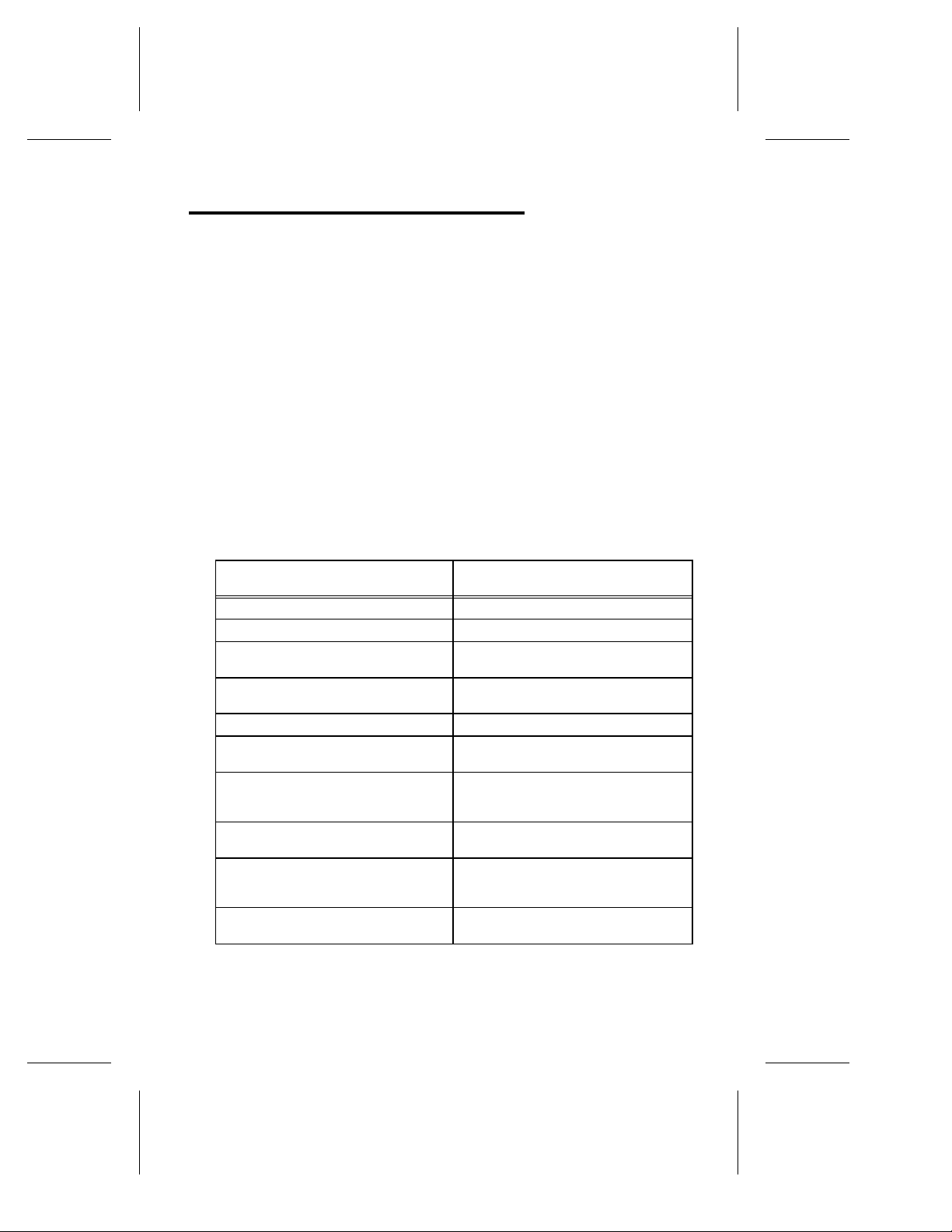
The two operation modes are described in the table below.
Table 1-2. AHA 1740A /17 42A /17 44 Ope ratio n Mo des
Standard Mode
(ISA compatible mode)
32-bit host transfers at 33 MBytes/sec. 32-bit host transfers at 33 MBytes/sec.
Addresses up to 16 MBytes host RAM. Addresses up to 4 Gigabytes host RAM.
AHA-1540 series mailbox structure
(compatible with AHA-1540 software).
Supports Fast SCSI devices up to
5 MBytes/sec.
Boot only from SCSI ID 0. Boot from any SCSI ID.
Drives spin up only at power-on. Drives spin up at power-on, or from
Disconnect/reconnect, parity checking,
and synchronous negotiation enable or
disabled for all SCSI targets.
Up to four host adapters can be installed in the system.
BIOS support for drives up to 1 Gigabyte in capacity under MS-DOS.
BIOS support for a maximum of 2
SCSI drives.
Enhanced Mode
(enhanced mailbox interface)
New high performance mailbox
structure.
Supports Fast SCSI devices up to
10 MBytes/sec.
SCSI Start Unit command.
These parameters can be enabled or
disabled on a per target basis.
Up to twelve host adapters can be
installed in the system.
BIOS support for drives up to 8
Gigabytes in capacity under MS-DOS
5.0 or higher.
BIOS support for up to 7 SCSI drives
(using MS-DOS 5.0 or higher).
1-5
Page 20

adaptec AHA-1740A/1742A/1744
System Caching Description
The AHA-1740A/1742A/1744 fully supports opera ting systems
caching to maximize overall system perfor man ce. Having RAM
on the host adapter can actually decr ease over all system perfo rmance while adding cost. Operating systems such as Novell
Ware, OS/2
cache and caching the same data in the operating system and on
the host adapter can bog down system performance.
Overall system performan ce is increased by incre asing the size of
the operating system cache (i.e. add more RAM to the system
motherboard), and by utilizing the advanced multithreading features of SCSI to minimize the mechanical limitations of SCSI
peripherals (such as disk seek times by using zero latency reads).
®
, UNIX, XENIX, DOS and Windows have built-in
®
Net-
1-6
Page 21

EISA-to- Fast SCSI Ho st Adapt er Overview
Product Specifications
The following table lists some of the physical product descr iption s
relating to the AHA-1740A/1742A/1744 Host Adapter s.
Table 1-3. AHA -174 0A/ 174 2A/ 174 4 Pro duct Speci fi cat io ns
Physical Dimensions
Length 13-3/8 inches
Width 5/8 inch
Height 5 inches
Standard EISA-compatible form factor
Power Requirements
+ 5.0 +/- 0.25 Volts at 2.9 Amps (maximum)
Environmental Requirements
Temperature -40° - 75° C (operating or storage)
Reliability Information
Mean Time Between Failures (MTBF): 100,000 hours
(calculated per Mil Handbook 217E, ground benign, 40 C)
Mean Time Between Failures (MTBF): (calculated)
1740A 60,462 hours
1742A 57,600 hours
1744 54,856 hours
Mean Time To Repair (MTTR): 30 minutes
1-7
Page 22

adaptec AHA-1740A/1742A/1744
Associated Documentation
The following documentation is also available for the
AHA-1740A/1742A/1744:
• Inst allation G u i d e
This includes basic installation information in this booklet. The download utility
adl.exe
is also described.
• Technical Reference Ma nua l
It includes a detailed description of the host adapter,
including jumper infor mation , mailbox interfac e descr iption, and troubleshootin g hints. Both the standar d mode
and enhanced mode are described in detail. If designin g
to the mailbox interface or target mode of the AHA1740A/1742A/1744, then this document is recommended.
❐
1-8
Page 23

Chapter Two
Hardware Installation
Unpacking and Inspection
The carrier is responsible for damage incu rre d during shipment.
In case of damage, have the carrier note the damage on both the
delivery receip t and the freig ht bill, then no tify you r freig ht company representative so that the necessary insuran ce claims can
be initiated.
After opening the shippin g containe r, use the packin g slip to verify receipt of the individual items listed on the slip. Retain the
shipping container and pac k ing m aterial for possible later re use
should it be necessary to return the equipment.
Note
The AHA 1740A/1742A/1744, like all electronic equipment, is
static sensitive. Please take the proper precautions when handling the board. Keep the board in its conductive wrapping
until it is configured and ready to be installed in your system.
2-1
Page 24

adaptec AHA-1740A/1742A/1744
Preparation
The configuration options for the AHA-1740A/1742A/1744 can be
selected from software. Therefor e, jumper s do not need to be
checked before installing the AHA-1740A/1742A/1744 into the
EISA system.
One exception is the AHA-1742A, since it contains an on-boar d
floppy controller . The on-board floppy contro ller is shipped with a
jumper installed at J6, position 6, floppy enabled. If the floppy
controller on the AHA-1742A is not used, this jumper should be
removed. Only on e floppy controller per EISA system can be
enabled.
The AHA-1740A/1742A/1744 has a jumper that can be changed.
This is the jumper block labeled J4, near the external connector.
This determines whether or not the AHA-1740A/1742A/1744 will
provide termination pow er to the SCSI bus. By default, the
jumper is installed and termination power is provided by the host
adapter. In general, the host adapter should always sup ply term inator power. However , no more than five SCSI devic es shou ld b e
configured to supply terminator pow er to a single SCSI bus.
2-2
Page 25

EISA-to- Fast SCSI Ho st Adapt er Hardware Inst alla tio n
SCSI Terminators
The SCSI bus must be terminated correctly to ensure proper operation. Only the first and last device on the SCSI bus (cable)
should have the terminating resistors installed. All other SCSI
devices should hav e the termin a ting resistor s remov ed. The following figure shows two examples of SCSI device conne ctions to
the AHA-1740A/1742A/1744 Host Adapter.
Figure 2-1. SCSI Dev i ce Te rmi nati o n
The AHA-1740A/1742A/1744 is a SCSI device, and has socketed
on-board terminator s that shou ld be removed if both the intern al
and external host adapter connectors are used. These can be reinstalled at a later time, if desired. On the AHA-1740A/1742A remove the RN5, RN6 and RN7 terminators. On the AHA-1744
remove the RN2, RN4 and RN5 terminators.
2-3
Page 26

adaptec AHA-1740A/1742A/1744
The RN5, RN6 and RN7 terminators on the AHA-1740A/1742A
are 150 ohm terminators. The RN2, RN4, and RN5 terminators
on the AHA-1744 are 330 ohm terminators. If the terminators
are removed and installed again in the AHA-1744, be sure to put
the 8-pin terminators in the 8-pin sock ets and the 10-pin termin ators in the 10-pin sockets.
All SCSI peripherals have a way to add or remove termin ation .
On some devices terminating resistors must be installed or removed. On others, only a switch need be toggled. Consult the
user manual for the par ticu lar SCSI devic e.
SCSI Parity
The AHA-1740A/1742A/1744 always generates SCSI parity.
SCSI parity checking can be enabled or disabled via the EISA
Configuration utility. If any attached SCSI device does not generate SCSI parity, then parity checkin g for that devic e should be
disabled.
SCSI ID
All SCSI devices have a parameter known as SCSI ID. The valid
values are:
0, 1, 2, 3, 4, 5, 6, 7
This parameter is chang ed via ju mper s or switc he s on most SCSI
peripherals. The SCSI ID of the AHA-1740A/1742A/1744 is 7
(highest priori ty) and can be changed via the EISA Configura tion
utility provided with the EISA system. The SCSI ID of the host
adapter is almost never changed fro m 7.
All attached SCSI devices must have a unique SCSI ID. If the
AHA-1740A/1742A/1744 is set to standard mode, the boot SCSI
disk drive must be set to 0.
2-4
Page 27

EISA-to- Fast SCSI Ho st Adapt er Hardware Inst alla tio n
Physical Installation in the System
The following steps should be follow ed to install the
AHA-1740A/1742A/1744 into the system:
1. Turn OFF the power to the comp uter system.
2. Remove the system cover acc ordin g to the direc tions of
the computer manufacturer.
3. If only an extern al SCSI subsystem is used, no intern al cabling is required. If an internal SCSI peripheral is used,
install a 50-pin SCSI ribbon cable to the host adapter.
This cable must be oriented correctly . Pin 1 of the SCSI
cable is designated by a red strip. Multicolor 50-pin ribbon cables signify pin 1 with a brown color. Pin 1 on the
host adapter 50-pin SCSI header is located on the lefthand side, farthest from the installation bracket and is
designated by the words PIN 1 on the bo ard adjacent to
the header. After locating pin 1 on the ho st adapter and
on the SCSI cable, carefu lly in sert the c onne ctor loc a ted
at the end of the long end of the cable into the host adapter connector. After ensur ing that all pins are lined up
and that the pin 1 orientation is correc t, fir mly seat the
connector to the board.
4. After installing the SCSI cable, the host adapter can be installed in any one of the 32-bit slots available in the host
computer. Some slots in EISA machines do not support
EISA bus mastering. The AHA-1740A/1742A/1744 cannot be used in such slots. If the AHA-1740A/1742A/1744
is accidentally installed in such a slot, the EISA Configuration program will rep or t an error. A different slot must
be chosen for the AHA-1740A/1742A/1744.
5. If an internal SC SI device is to be used, it should be installed in the drive bays in accordanc e with the direc tions
on the peripher al. The prop er power sup ply mus t be connected to the SCSI peripheral device.
2-5
Page 28

adaptec AHA-1740A/1742A/1744
6. The 50-pin SCSI ribbon cable can now be attached to each
SCSI device. Refer to the device’s installation instructions to ensure proper pin 1 orientation . Pin 1 orientation
must be consistent throughout the system. Keep the ribbon cable neatly dressed away from the ventilation slots
in the computer system. Keep the ribbon cable dressed
away from possible electrical noise sou rces or noise sensitive components, particularly large microprocessors, memory boards, switch in g power supplies, and analog da ta
acquisition board s. If the internal con fig uration requ ir es
the cable to come near noise sensitive circuits, make sure
that the cable crosses the boards at right angles and is
near the noise sensitive circuits for the shortest distance
possible.
WARNING
The AHA-1740A/1742A requires single-ended devices.
The AHA-1744 requires differential devices. Failure
to match drive types can result in electrical damage to
the host adapter and the peripherals.
7. Carefully reinstall the cover of the computer.
2-6
8. If an external SCSI subsystem is to be installed, it can
now be cabled to the external SCSI connec tor pro jectin g
from the shielding brack et on the back of the AHA1740A/1742A/1744 Host Adapter. Th e proper shielded
SCSI cable must be used for proper operation. The external connector on the AHA-1740A/1742A/1744 is a 50-pin
high densi ty type conn ec to r that en sur es cor r ec t pin 1 orientation on the host adapter. The subsystem, cables, and
SCSI terminators must be installed in accordance with
the directions provided with the external SCSI subsystem. The addresses selected for external SCSI devices
must not overlap with the addresses of the host adapter
or any other SCSI devices attached internally.
❐
Page 29

Chapter Four
Multiple Host Adapter Support
The AHA-1740A/1742A/1744 supports more than one host
adapter in the system. The maximum number of host adapters
supported depend s on the operatin g mode of the host adapter.
Standard Mod e
An EISA system can support up to a maximum of four AHA1740A/1742A/1744 adapters in standard mode; limited by the four
available DMA channels: 0, 5, 6 and 7. The host adapters must be
set to unique Interrupt chan nel s (IRQ), DMA chan ne l s, I/O port
addresses, and BIOS addresses.
Enhanced Mode
An EISA system supports up to a maximum of twelve
AHA-1740A/1742A/1744 adapters in enhanced mode; limited by
the number of available EISA bus master supporting slots. Each
AHA-1740A/1742A/1744 installed in enhanced mode by default
shares IRQ 11. This value can be chan ged with the MCS EISA
Configuration utility by selectin g the Ho st Ad ap ter Int erfa ce
Mode and pressing Cntrl + R key combination to view system
resources (see Figure 3-3). Each AHA-1740A/1742A/1744 can be
set to a unique IRQ to maximize system performance. The IRQ
cannot be changed with the AMI EISA Configuration utility
cfg.exe
(
) or the Phoenix EISA Configuration utility (
ptlecu.exe
).
4-1
Page 30

adaptec AHA-1740A/1742A/1744
Standard and Enhanced Modes
In general, the host adapter SCSI ID does not need to be changed
from the default of 7. Even if two host adapters are installed in
the same computer, each wo uld have its own SCSI bus (cable),
and thus each host adapter would still be set to SCSI ID 7.
This value should only be changed if more than one host adapter
is on the same SCSI bus (cable). This could occur in an application that utilizes the target mode of the AHA-1740A/1742A/1744.
Unlike previous Adaptec SCSI host adapters, the use of multiple
host adapter BIOSs can be enabled on you r system. If any config u ration options for the SCSI Device Config u ration are chang ed
with the EISA Configuration utility, then the BIOS for that host
adapter should be enabled; the host adapter BIOS reads that configuration infor ma tion from the EISA CMOS. If the AHA1740A/1742A/1744 BIOS is disabled, all configuration options are
set to the default values shown in Figure 3-5 and 3-6.
Any valid BIOS in the system is installed in an order of priority.
The lowest BIOS address has the highest prio rity . For example, a
host adapter BIOS at address CC000h would be loaded before a
host adapter BIOS at address DC000h.
The Adaptec ASPI
Consult the ASPI software use r manual for proper loadin g of device drivers with multiple host adapters.
❐
4-2
software supports multiple host adapters.
Page 31

Chapter Five
Adaptec Download Utility
The Adaptec Download utility (ADL) is used to download a differ ent version of the microcode software to the AHA-1744. This
chapter describes the operation of the program which affects only
the AHA-1744; the AHA-1740A/1742A do not support micr ocode
reprogr amming . Althoug h this guid e does not cove r the
AHA-1740 operation referen ces are made to the host adapter, in
this chapter, because of the similarity in operation with the
program. The
mat, verify or erase the boot sector of SCSI fixed disk drives con nected to the AHA-1740A/1742A/1744.
Using this program to download the microcode is not necessary
when the host adapter is initially installed. The host adapter is
shipped with the standard mode and enhanc ed mode firmwar e,
which can coexist in the host adapter. You use the EISA Configuration utility to change the operation modes of the AHA-1744.
adl
The
the
F1 key.
program is run by selecting the
adl
program, online help is always available by pressing the
adl.exe
program can also be used to low-lev el for -
adl.exe
file. As you use
adl
Running the ADL Program
When running the
files are in the same sub-directory.
•
sys$err.dta
•
sys$help.dta
•
sys$msg.dta
•
firmhlp.hlp
adl
program, ensur e that the followin g suppor t
Support files for
Support files for
Support files for
Support files for
adl.exe
adl.exe
adl.exe
adl.exe
5-1
Page 32

adaptec AHA-1740A/1742A/1744
Also ensure that the followin g microco de files are presen t.
•
standard.hex
•
enhanced.hex
To run the program, type adl. The first screen displays.
Standard mode microco de
Enhanced mode mic ro co de
Figure 5-1. Host Adapter Listing
If the program d oes not pr oper ly disp lay on a monoch ro me or
VGA monitor, you can type:
adl /m or adl /mono
to run the program in monochrome mode. If the screen does not
display properly try typing:
mode bw80
adl
before running the
5-2
program.
Page 33

EISA-to- Fast SCSI Ho st Adapt er Adaptec Dow nlo ad Utilit y
The installed host adapters are displayed. In this example, one
AHA-1744 is installed in slot 3. It is currently set to enhanced
mode. Both standard mode and enhan ced mode fir mwar e can be
downloaded, regardless of the current operation mode of the
AHA-1744.
Select the desired host adapter and press Enter. The Main
Menu displays.
Figure 5-2. ADL Main Menu
Three options are available and each option is described in the following sectio ns:
• Download Firmwar e
• Firmware Information
• Low-Level Format
5-3
Page 34

adaptec AHA-1740A/1742A/1744
Download Firmware
After selecting Downlo ad Fir mware, the next screen displays.
Figure 5-3. Do wnl oad Fi rmwa re Screen
Enter the filename of the microcode that you are going to download to the host adapter. Enter standard.hex for standard mode
and enhanced.hex for enhan c ed mode . The Mode field mus t be
set to standard to download the standard mode micr ocod e, and
enhanced to down load enhan ced mode firmwar e. The Mode field
can be toggled by selecting the field and pressing the + or - keys.
5-4
Page 35

EISA-to- Fast SCSI Ho st Adapt er Adaptec Dow nlo ad Utilit y
After entering the filename, press the Esc key. The next screen
displays.
Figure 5-4. Downloa d Warn ing Me ssag e Screen
The checksum of the micro co de is displayed, whic h uniqu ely iden tifies the microcode. Select Y to continu e with the dow nlo ad, or N
to stop. The download can take up to 45 seconds to complete.
Once completed, the screen displays the Download Complete message. Press Esc to continue.
Note
The type of firmware download (standard or enhanced) does no t
affect the operation m ode of the AHA-1744. This can only be
changed with the EISA Configuration utility.
5-5
Page 36

adaptec AHA-1740A/1742A/1744
Firmware Information
This menu option is used to display information on the installed
firmware. If the AHA-1740A/1742A1744 is operating in the stand ard mode, only information on the standard mode firmware is displayed. If the AHA-1740A/1742A/1744 is operating in the
enhanced mode, only information on the enhan ced mode fir mwar e
is displayed.
The following screen shows the enhanced mode firmware
information:.
5-6
Figure 5-5. Enhanced Mo de Fi rmwa re Informa tio n
Page 37

EISA-to- Fast SCSI Ho st Adapt er Adaptec Dow nlo ad Utilit y
Low-Level Forma t
This option is used to low-level format, verify , or erase the boot
sector of attached SCSI fixed disks on the AHA-1740A/1742A/
1744.
When selected, all attached SCSI devices are displayed.
Figure 5-6. Low-Level Forma t Devi ce Sele ction Scree n
Select a device and press the Enter key.
5-7
Page 38

adaptec AHA-1740A/1742A/1744
The Low- Lev el Fo rma t Opt io ns screen displays.
Figure 5-7. Low-Lev el For mat Optio n Selecti o n Scre en
Selecting Format/Ver ify causes th e AHA-1740A/ 1742A/1744 to
send a SCSI Format Unit command to the selected disk drive
which performs a low-lev el for mat of the disk. When the SCSI
Format Unit command is complete, the SCSI Verif y command is
sent to verify the data on the media.
WARNING
Selecting Erase Boot Sector causes the host adapter card to
write data to the boot sector of the selected disk drive. This
destroys the boot record and partition table for the disk drive,
and makes any data on the disk drive unavailable.
5-8
Page 39

EISA-to- Fast SCSI Ho st Adapt er Adaptec Dow nlo ad Utilit y
Exiting the ADL Program
To exit the
screen displays.
Select Yes to exit.
adl
program, pre ss the Esc key and the following
Figure 5-8. Ex it ing the AD L Pro gra m
❐
5-9
Page 40

Page 41

Chapter Six
Host Adapter BIOS Operation
The AHA-1740A/1742A/1744 BIOS operates in two modes: standard and enhanced . The mode of operation is selected with the use
of the EISA Configuration utility supplied w ith you EISA computer system.
Standard Mod e Operat ion
When the adapter BIOS is operating in the standard mode, only
SCSI IDs 0 and 1 are supported. The fixed disk that is config ur ed
as SCSI ID 0 is the boot disk drive. The BIOS only looks for a
disk at SCSI ID 1 if a disk drive was found at SCSI ID 0 and no
non-SCSI disk drives are installed.
The following message appear s on the display when you boot the
computer system an d the standar d operation mode i s selected.
Adaptec AHA-1740 BIOS v1.34
Copyright 1991 Adaptec, Inc.
[Standard Mode]
Target 0 - Drive C: (80h)
Target 1 - Device not found.
Figure 6-1. Stan dard B IO S Boo t Mess age
6-1
Page 42

adaptec AHA-1740A/1742A/1744
The BIOS version and operation mode of the AHA1740A/1742A/1744 appear at the top of the message, followed by a
list of the identified SCSI devices.
In the example shown, a SCSI fixed disk was found at SCSI ID 0
and installed as drive C. No SCSI fixed disks were found at SCSI
ID 1. Drive C is also referr ed to as drive 80h with an interru pt of
13, which is the software inter rupt for disk I/O. If a second drive
were installed with a SCSI ID of 1, it would be referred to as
drive D or 81h. Drives 82h to 8Fh are n ot curr ently supported by
the adapter BIOS, so no search is made for other SCSI IDs (2
through 6) as valid disk drives.
Caution should be used when using the AHA-1740A/1742A/1744
in standard mode, since a chec k is not made for the type of devic e
being installed. For example, if a SCSI tape drive is installed at
SCSI ID 0, the AHA-1740A/1742A/1744 BIOS would install it as
drive C. This would not work, since the adapter BIOS is designed
to work with SCSI fixed disks only (or remov able media if the
media is not removed while the system is turned on).
The adapter BIOS can also install removable media devic es as
drive C or drive D. In general, this should not be done. The host
adapter BIOS does not support the removing of media, while the
computer system is opera ting . If the media is removed while the
computer system is opera ting you may exper ien ce data loss. Removable media (under DOS) should be installed with Adaptec
ASPI software.
6-2
Page 43

EISA-to- Fast SCSI Ho st Adapt er Host Adapte r BIOS Opera tio n
Enhanced Mode Operation
The enhanced mode operation enables the adapter BIOS to identify all installed fixed disks with a valid SCSI ID.
All SCSI IDs with the BIOS support option enabled, using the
EISA Configuration utility, are scanned. The devices are
scanned, starting from SCSI ID 0 and increasing until two SCSI
fixed disks are found or all supported SCSI IDs have been
searched. Those device s found that are not valid fixed disks, such
as SCSI tape drives, CD-ROM drives, etc., will not be installed.
However, the SCSI Inquiry data, the manufactu r er and model
number for these devic es, is sh own.
The following message appears when you boot the computer system with the enhanced mode operation selected.
Adaptec AHA-1740 BIOS v1.34
Copyright 1991 Adaptec, Inc.
[Standard Mode]
Target 0 - QUANTUM P40S 940-40-94XX - Drive C: (80h)
Target 2 - CONNER CP340 (40mb 3.5) - Drive D: (81h)
Target 4 - CHINON CD-ROM CDS-431
Figure 6-2. Enhanced BIOS Boot Message
Installed devices display the SCSI Inquiry data follow ed by the
drive C (80h) or drive D (81h) designation . Drive s 82h through
8Fh are supported with the adapter BIOS run ning DOS 5 or
higher.
6-3
Page 44

adaptec AHA-1740A/1742A/1744
If Error if Device Not Found is enabled, throu gh the EISA Configuration utility, then you will see a screen similar to the one
shown below:
Adaptec AHA-1740 BIOS v1.34
Copyright 1991 Adaptec, Inc.
[Standard Mode]
Target 0 - QUANTUM P40S 940-40-94XX - Drive C: (80h)
Target 1 - Device not found!
Target 2 - CONNER CP340 (40mb 3.5) - Drive D: (81h)
Target 3 - Device not found!
Target 4 - CHINON CD-ROM CDS-431
Target 5 - Device not found!
Target 6 - Device not found!
Figure 6-3. Boo t Mes sage With Err o r Det ecti on En ab led
By default, removable media disk drives are not installed by the
adapter BIOS. To have removable media installed by the adapter
BIOS, select the fr option from th e EISA Config u ra tion utility .
Generally, this shou ld not be done. The adapter BIOS, in eith er
operation mode, does not support the removin g of med ia dur ing
system operation. If the media is removed while the system is
operating data loss could occur. Removable media (under DOS)
should be installed with Adaptec ASPI softwar e.
❐
6-4
Page 45

Chapter Seven
Troubleshooting
The AHA-1740A/1742A/1744 executes a self-test diagnostics
when the system power is turned on or after a Hard Reset. The
self-test diagnostics tests the CPU operation, performs a checksum test on the EPROM and checks the data transfer paths on
the host adapter. The host system diagnostics may perform a
more extensiv e
diagnostics by re adin g an d wr iting data to memor y .
Determining Problems Using the LED
The red Light-Emitting Diode (LED ) on the host adapter indicates the result of the self-test diagnostic. When the powe r is
first applied to the host adapter, the LED is turned on. Under
normal operation the LED turn s off when the self-test diagnostics
is complete. The LED remains off until the host initiates activity
on the SCSI bus or I/O port. If the self-test diagnostics fails the
LED will flash a code indicating the type of test failure. The LED
will flash once, twice (in rapid succession) or three times (in rapid
succession) followed by a longer pause to indicate the type of test
failure. The flash code is repeated continu ously u ntil the hos t
adapter is powered -off , re set, or repaired.
If you are running the self-test diagnostic for fault-isolation purposes disconnect the SCSI interface cable. However, ensure that
at least one set of SCSI terminator s are installed on the last SCSI
device. If the SCSI terminators are not present the LED remains
on; indicating that the AHA-1740A/1742A/1744 is receiving an
active RST signal. Continuou s execution of the self-test diagnostics on the AHA-1740A/1742A can be enabled by inserting the
diagnostic jumper pair on pin 4 of jumper 6. For the AHA-1744 insert the jumper pair on pin 4 of jumper 5.
7-1
Page 46

adaptec AHA-1740A/1742A/1744
The following table lists the LED flash codes with the associ ated
failure descriptions.
Table 7-1. AHA 1740A /1742A /1 744 LED Fla sh Cod es
Flash Code Failure Description
LED Remains On Host Adapter Control Processor failure. Terminators
1 flash RAM test failed.
2 flashes AIC-6251 SCSI protocol chip verification fai led.
3 flashes FIFO write/read data path test failed.
Continuous flashing EEPROM has not been programmed (AHA-1744 only).
If any of the flash codes occur, turn the compu ter system OFF, remove the host adapter and inspect it for physical damage. Ensure that the EPROMs are correctly in stalled and firmly seated,
there are no missing or damaged compo nents, the re are no broken
wires, and no conductive debris is on the host adapter. If no
physical damage is found, return the AHA-1740A/1742A/1744 for
repair to the dealer or distributor where the host adapter was
purchased.
inoperative, missing or not powered-on or the card
enable has not been asserted after reset.
The host adapter is cleaned and inspected and tested using a
burn-in per iod before it is shipped. Exerc ise cau tion when handling the host adapter and keep it in the protectiv e, con du ctiv e,
wrapping until you install it. With these simple precautions, you
can avoid most of the host adapter failures and damage can normally be avoided.
Problems Detected During Installation
This section may be useful to correct problems related to
installation.
If the system will not boot from the floppy di skette drive after
initial hardware installation, the following item s should be
checked:
7-2
Page 47

EISA-to-Fast SC SI Host Ada pter Troubleshoo ting
• LED on host adapter after power-on - The LED on the
AHA-1740A/1742A/1744 should come on briefly after turning the sys tem power on. The LED shou ld tur n off wh en
a request is sent to the host adapter.
• LED on host adapter during operation - If the LED on the
AHA-1740A/1742A/1744 is always on, the orientation of
the SCSI cable between the ho st adapter and the drive
may be reversed. For the proper or ien tation re fer to the
AHA-1740A/1742A/1744 Installation Guide.
• If the LED begins to blink at regular in te rvals then the
host adapter has detected an internal failu r e and should
be returned for repair or replac emen t to the place of purchase. An error message may also appear on the screen.
If the AHA-1740A/1742A/1744 BIOS message does not display on
the screen then the computer system is not recognizing the host
adapter.
• Check the AHA-1740A/1742A/1744 BIOS address to
ensure it is not conflicting with other host adapters installed in the computer system.
• Try a different BIOS address. For the proper addr es s
refer to the AHA-1740A/1742A/1744 I nstallation Guide.
• Change the BIOS wait-state jumper. For the proper
jumper settings refer to the AHA-1740A/1742A /1744
Insta llation Guid e .
• Try changing the BIOS address from the default of
CC000h to DC000h, or some other available value.
If the following message displays:
host adapter not found at port 330h
Check the port address setting. Verify the correct installation of
the SCSI cable. An inverted or misplaced internal SCSI cable,
generating a forced SCSI reset, may be causin g the problem.
7-3
Page 48

adaptec AHA-1740A/1742A/1744
Problems Booting the System from a SCSI Drive
•
Make sure that both standar d fix ed disks are mapped out
of the system.
• Make sure that the SCSI boot drive address is set to SCSI
ID 0:0. Check the drive installation manual for information about setting the SCSI ID for that device. The
Return Installed Devices utility in the Onboard utilities
can also be used to determine the SCSI addresses of peripherals on the SCSI bus.
• Make sure that SCSI parity is consistently enabled or dis-
abled on all devices on the SCSI bus.
• Verify the proper installation and configuration of the
host adapter and SCSI devices.
• Power should be cy cled O FF and ON after chan g in g any
setup
values on a host adapter,
to be sure that a DOS format operation has been succe ssfully completed.
program, or S C SI devic e,
• Make sure that the SCSI bus is properly terminated.
• Make sure that the intended boot disk has an active DOS
partition and a DOS format.
• Check the cabling.
Problems Using a SCSI and a Standard Disk
Drive
The drives are config u r ed a s SCSI disk drive D an d stan dar d di sk
drive C.
• Make sure that the second standard fixed disk is mapped
out of the system.
7-4
Page 49

EISA-to-Fast SC SI Host Ada pter Troubleshoo ting
• Make sure that the SCSI drive to be used as drive D is set
to SCSI ID 0:0. Check the drive manual for information
on setting the SCSI ID for that device. The Return Installed Devices utility in the Onboard utilities can also be
used to determine the SCSI addre sses of periph erals on
the SCSI bus.
• Make sure that SCSI parity is consistently enabled or dis-
abled on all devices on the SCSI bus.
• Verify that the host adapter and the SCSI devices are
properly configured and installed.
• Power should be cy cled O FF and ON after chan g in g any
setup
values on a host adapter,
to be sure that the new initial values are loaded.
program, or S C SI devic e
• Make sure that the SCSI bus is properly terminated.
• Make sure that the disk has a DOS partition and a DOS
format.
• Check the cabling.
Problems Using Two SCSI Drives
The drives are config u r ed a s SCSI disk drive D an d SCSI disk
drive C.
• Make sure that both standard fixed disks are mapped ou t
setup
of the system with the
program.
• Make sure that the SCSI drive to be used as drive D is set
to SCSI ID 0:1 or 1:0. Check the drive manual for information on setting the SCSI ID for that device. The
Return Installed Devices utility in the Onboard utilities
can also be used to determine the SCSI addresses of peripherals on the SCSI bus.
7-5
Page 50

adaptec AHA-1740A/1742A/1744
• Power should be cycled OFF and ON after chan g in g any
setup
values on a host adapter,
to be sure that the new initial values are loaded.
program, or S C SI devic e
• Make sure that SCSI parity is consistently enabled or dis-
abled on all devices on the SCSI bus.
• Verify that the host adapter and the SCSI devices are
properly configured and installed.
• Make sure that the SCSI bus is proper ly termin ated.
• Make sure that the disk has a DOS partition and a DOS
format.
• System works erratically, hangs, or the host adapter can-
not always find the drives.
• Check SCSI parity for consistency.
• Check termination.
• Check cable length and integrity.
• If host adapter and drive LED remain on during a hang
condition, make sure that the SCSI drive conforms to the
Common Command Set Revision 4B (CCS 4B).
If only the host adapter LED remains on during a hang, it is probably a host adapter to computer system interface proble m. The
system may not be capable of First-Party DMA tran sfer s. Check
with the system manufactu rer for inf orm ation.
Some older motherboard BIOS do not suppor t freefor m data for
the EISA configuration. This support is require d in order to
changed the defaul t Host Adapter options. If freeform data is not
supported, the AHA-1740A/1742A/1744 can still be used, but the
Host Adapter option defaul ts will always be used.
❐
7-6
Page 51

Appendix A
Disk Drives Over 1 Gigabyte
Extended Translation (Using DOS 5)
Adaptec host adapters have alway s suppor ted the full range of
disk drive sizes under all major operating systems. As disk drives
have recently gro wn bey ond 1 Gigaby te in formatted cap acity ,
they have run up agains t the DOS 1024 cylinder limit.
To continue to provide suppor t of all SCSI disk drive cap acities
under DOS, Adaptec has introduced extended translation for the
AHA-1740A/1742A/1744. This new feature bypasses the DOS disk
capacity limit and supports disk drives up to 8 Gigabytes in size
under DOS, providing room for years of disk drive evolution.
The DOS 1 Gigabyte Limit
All versions of DOS are limited to 1024 cylinders of capacity per
drive. The standard translation scheme for SCSI host adapters,
using 64 heads and 32 sectors, provides a maximum ac cessible
capacity of 1 Gigabyte.
To eliminate the 1 Gigabyte limit, Adaptec’s new extended translation feature uses 255 heads and 63 sectors, ex ten din g the disk
drive capacity limit under DOS to 8 Gigabytes.
A-1
Page 52

adaptec AHA-1740A/1742A/1744
When to Use Extended Translation
With DOS Version 5 Only
NetWare 386 and the newer versions of UNIX do not share the
1024 cylinder limit of DOS and do not requ ir e exten de d tran slation to support large disk drives. O S/2 does not cu rr en tly supp ort
extended translation .
Drives With Mixed Partitions
Do not use extended translation on drives formatted with two or
more partitions for different operating systems. Use standard
translation. The sum of the DOS partitions will be less than 1
Gigabyte. Partitions for UNIX and NetWare can be lar g er than 1
Gigabyte when using standard translation.
Note
UNIX is understood to be ATT/USL all versions, SCO v3.2.4 (or
later) and ISC v3.0 (or later).
Using Extended Translation
CAUTION
If you have already partitioned a large disk drive with one
translation method, conversion to another method will erase
your data. Be sure to back up your disk drive prior to any
change in the translation method used.
A-2
Page 53

EISA-to-Fast SCSI Host Adapte r Disk Drives Over 1 Gigabyte
Using Fdisk
To install a new disk, or to re-partition an existing disk, use the
fdisk
DOS utility as you normally would. The cylinder size increases to 8 MBytes when you enable extended translation. The
size of the partition you request must therefore be a multiple of
8 MBytes. If you request a partition size that is not a multiple of
fdisk
8 MBytes,
8 MBytes.
will round up to the nearest whole multiple of
Load ASW-1410 v3.0a
Load ASW-1410 v3.0a for ASPI support of non-di sk peripher al devices. The ASW-1410 v3.0a is fully compatible with extended
translation in the AHA-1740A/1742A.
Questions and Answers About Extended
Translation
What happen s if I enabl e ex ten ded tran sl ation with SCSI
drives that are less than 1 Gigabyte in capacity?
Drives handle d by the BIO S will use exte nd ed tran slation provided they are over 1 Gigabyte in formatted capacity. Driv es with
less than 1 Gigabyte of formatted capacity will use standard
translation regardless of whethe r extended tran slation is enabled.
Drives handled by the disk driv er
standard translation and not be capable of DOS partitions over 1
Gigabyte.
What if I have more than two fixed disk drives on the
AHA-1740A/1742A?
You can use up to seven fixed disk dr ive s und er the BIOS
provided you are runn in g DOS 5.0.
aspidisk.sys
will continue to use
A-3
Page 54

adaptec AHA-1740A/1742A/1744
What if I use olde r versi o ns of software dri ve rs wi th ex tended translatio n enabled?
To protect your data, the host adapter will lock out any driver
that does not identify itself as capable of extended translation . If
you need to use software that is not compatible with exten ded
translation, do not enable extended translation.
Adaptec’s ASW-1410 v3.0a (and later) is the appropriate ASPI
manager software to use with extend ed tran slation enabled.
❐
A-4
Page 55

Appendix B
Loading the I/O Operating
Environment Software
DOS/Windows
Under DOS 5.0 or higher, up to seven SCSI fixed di sk drives can
be connected to the 1740A/1742A/1744 without additional software. (Older versions of DOS support up to two disk drives).
The host adapter treats removable media drives as fixed di sk
drives provided you en able T rea t Removable Di sks Under BIO S
as Fixed Disks in Advanced Configu r ation Option s, and do not remove the media while your computer power is on.
Additional software is requ ir ed if you desir e to do the following :
• Treat removable media devices a s removable while y our
computer is running.
• Support more than two fixed disk drives under version s of
DOS prior to MS-DOS 5.0.
• Use devices other than fixed disk driv es such a s SCSI
tape, CD-ROM, scan n ers, etc.
Refer to the documentation receive d with your opera ting environ ment software package for instructions on loading your SCSI I/O
Operating Env ir onmen t for ver sions of DO S prio r to MS-DO S 5.0
B-1
Page 56

adaptec AHA-1740A/1742A/1744
Novell NetWare
NetWare 4.x includes the Adaptec I/O Operatin g Enviro nme nt
and does not require addition al softwar e.
To load software for Novell NetWare 286 2.x and 386 3.x follow
the instructions included in the ASW-1440 software packag e.
OS/2
IBM® OS/2 2.0 and Microsoft® OS/2 1.30.1 include the Adaptec
I/O Operating Env ir onment and do not require addi tional
software.
To use the AHA-1740A/1742A/1744 under OS/2 1.3 follow the instructions in the ASW-1220/1420 version 1.3 software produc t.
Unix
Major versions of UNIX includ e the Adaptec I/O Operatin g Environment and support the AHA-1740A/1742A/1744 witho ut additional software. Current versio ns of SCO
and Sunsoft Interactive UNIX
1744.
❐
B-2
®
support the AHA-1740A/1742A/
UNIX, USL UNIX®,
Page 57

Glossary
Adapter Command
A command transmitted to the host adapter using the Command
Data Out Port and the Data In Port. The commands are
sequenced using the Control Port, the Status Port, and the Interrupt Flag Port. Abbreviated as IOCP command.
AEN
See Asynchronou s Event Notification
AHA-1540
Adaptec host adapter for connecting SCSI devices to the PC-AT
backplane bus. The AHA-1740A/42A/ 44 is an enhanced version of
the AHA-1540.
AHA-1540B
The enhanced high-performan ce Adaptec host adapter for connecting SCSI devices to the PC-AT backplan e bus.
AHA-1542B
The enhanced high-performan ce Adaptec host adapter for connecting SCSI devices and standard IBM-compa tible floppy disk
devices to the PC-AT backplane bus.
AHA-1740A/42A/44
Either the AHA-1740A, 1742A or the AHA-1744.
ASPI
Advanced SCSI Prog rammin g Inter fac e. A software architec tu re
which perm its devic e modu les to migrate acr oss differ en t har dware by communicating with the hardware through a passthrough interfac e to a manager writ ten to the specific hardw are .
Asynchronous Data Transfer
Data transfer per formed by the SCSI interf ace involv ing the in terlocking of a signal to the initiator (REQ) and a signal to the target
(ACK) such that each step of the data transfer protocol mu st
occur before the next step can beg in. Characterized by a low data
®
GL-1
Page 58

adaptec AHA-1740A/1742A/1744
rate and indepen de nc e of exter nal timing constr aints, includin g
cable length an d circuit response times.
Asynchronous Event Notification
A process by which a target can send unsolicited sense info rmation to an initiator using the Send command in order to inform
the initiator about the occurrence of an important unusual
occur renc e.
AT Bus
The Industry Standard Architecture bus.
Bus Device Reset
A SCSI message that clears all activity in the target to which it is
addressed.
Byte
An eight-bit unit of data. An octet. A byte is normally the smallest addressable unit of a memory and the unit of transfer on the
SCSI bus.
CCB
See Command Control Block
CCS
See Common Command Set
CDB
See Command Descriptor Block
Command Control Block
A software object prepared by the host micr ocomp uter softwar e
for the host adapter to provide it all the contro l infor mation it
needs to execute a SCSI command. Abbreviated CCB.
Command Descriptor Block
A block of information passed across the SCSI bus to provide the
command, parameter, and addr ess information necessary for the
target to execute the desired func tion s. Prepar ed by the host software and placed in the CCB to be passed to the target by the host
adapter. Abbreviated CDB.
GL-2
Page 59

EISA-to-Fast SC SI Host Ada pter Glossary
Common Command Set
A de facto standard SCSI command set for commun ic ation with
fixed disk drives. The Common Command Set (CCS) is the basis
for the SCSI-2 command set for all types of peripheral devices.
Configuration
The operation of configu ring a device on the EISA bus through
access of registers in the devic e by the ho st. It replaces the
method of using jumper s common on ISA bus devic es.
Control Microprocessor
An integrated circuit comp uter used to execute the softwar e that
controls the host adapter’s operation.
Device Driver
A program that is linked with, or attach ed to, an operatin g system to map the software interface of the operating system to the
requiremen ts of attached periph eral dev ice s and host adapters.
Under ASPI, the main component associated with the board is
known as a Manager.
DMA
See Direct Memory Acces s
Differential
A term referring to the electric al ch ar acter istics of the sign al s
used on the SCSI bus interface. Differential signals occupy two
conductor s with a positive (+) and negative (-) polar ity c ompon en t
of the signal. This minimizes the effect of common mode sign al
noise and allows the SCSI bus to operate reliably over greater distances at a higher speed.
Direct Memory Acces s
A mechanism that allows hardware control of the transfer of
streams of data to or from the main memory of a computing system. The mechanism may requir e setup by the host software.
After initialization, it automatically sequences the required data
transfer and provides the necessary addr ess infor mation .
Disconnect /Reconnect
Disconnect is the function that occurs when a target releases control of the SCSI bus, allowing the bus to go to the Bus Free phase.
GL-3
Page 60

adaptec AHA-1740A/1742A/1744
Reconnect is the function that occurs when a target selects an
initiator to continue an oper ation after a disconne ct.
EEPROM
Electrically-Er asable Pro grammable Read Only Memor y. An integrated circuit used to store the host adapter firmwar e, whic h
allows both mode download and firmw ar e upgrade w hile incircu it .
EISA
Extended Indu stry Standard Architec tu re . A superset standard of
the 8- and 16-bit ISA standard which allows 32 bits of data to be
transferred ac ro ss the bus at up to 33 MBytes/secon d.
Enhanced Mode
The operation mode of the AHA-1740A/1742A/1744 to take full advantage of the addressing range and register set available under
EISA. It is not compatible with earlier revisions of ASPI managers and drivers.
EPROM
Erasable Programmable Read Only Memory. An integrated circuit used to store the host adapter BIOS.
FIFO
First In/First Out. A queu in g order in whic h items are remov ed
from the queue for execution in the same order in which they are
placed in the queue. An integr ated circ u it that buffers data in
such a manner that each by te placed in the buffer is remov ed
from the buffer in the same order .
Firmware
The software that controls and manage s the host adapter. It is
firm as opposed to soft because i t is designed into the host adapt-
er and cannot be modified by the user.
Host
A microcomputer in which a host adapter is installed. The host
uses software to request the services of the hos t adapter in transferring information to and from periph eral dev ic es attached to the
SCSI bus connector of the host adapter.
GL-4
Page 61

EISA-to-Fast SC SI Host Ada pter Glossary
Host Adapter
A hardware printed circu it board that installs in a standard
microcompu ter backplan e an d provid es a SCSI bus conne ction so
that SCSI devices can be connec ted to the micr oc ompu ter . A host
adapter is intelligent if it has a simple high -lev el software inter-
face to the microcomputer . A host adapter is dumb if the microcomputer mus t directly man age the SCSI protoc ol usin g the
microcompu ter processor .
IBM PC-AT Compatible
Any computer system that emul ates exac tly the IBM PC-AT and
that uses an ISA backplane bus.
Industry Standard Architecture
The IBM PC-AT function s have been duplic ated by a number of
manufactur ers. All the IBM PC-AT c ompatible mach ines use a
backplane bus that very closely emu lates the function of the backplane bus of the PC-AT. Because of the broad usage of this bus
structure, it has become know n as the Industr y Standar d Arch itecture bus, even thoug h there is no presently acc epted standard
for the bu s.
Initiator
A SCSI device that requests an operation to be performed by
another SCSI device (th e target). Th e initiator pro vid es all the
command information and parameters required to perform the
operation, but the details of the operation are actually sequenced
by the target.
ISA
See Industry Standard Arc hitec tu re
Logical Un i t
A physical or virtual devic e addressed thr ou gh a target.
Logical Un it Numb er
An encoded three-bit iden tifier for a logical unit.
LU
See Logical Unit
LUN
See Logical Unit Number
GL-5
Page 62

adaptec AHA-1740A/1742A/1744
Mailbox In
An area in main memory assigned by the host microcomputer software for communication with the host adapter. The host adapter
places status and pointer infor mation in entries in the Mailbox In
(MBI) to indicate to the host microcomputer what oper a tions have
been completed or what information must be obtained from the
host microcompu te r.
Mailbox Out
An area in main memory assigned by the host microcomputer software for communication with the host adapter. The microcomputer software places commands and pointer information in
entries in the Mailbox Out (MBO) to indicate what operation s
should be started by the host adapter.
Manager
The component of a drive r whic h is spec ific to a particular board
architecture and presents a standar d ASPI pass-through interface for use by the peripheral- spec ific compone nt of the driver,
known as a module.
MBI
See Mailbox In.
MBO
See Mailbox Out.
Multi-tasking Operation
The execution of co mmand s in such a way tha t more than one
command is in progress at the same time, allowing the system to
take advantage of over lappin g activ i ties by using re sourc es tha t
are temporarily no t requ ired for other operations. More than on e
program or more than one portion of a program may be operating
in parallel.
PC-AT
A family of small computers sold by IBM, also called the Person al
Computer/AT family of compute rs. The name is trademarked by
IBM.
GL-6
Page 63

EISA-to-Fast SC SI Host Ada pter Glossary
RAM
Random Access Memory. Memory of which any byte can be
accessed direc tly in a single memory cyc le. Infor mation can be
read from and written to the memory .
Scatt er/Gather
A device driver feature that allows the host adapter to modify the
transfer data pointer so that a single host ad apter transfe r can
transfer to many segmen ts of memory in a single transfe r, minimizing interrupts and overhead.
SCB
SCSI Control Block. The mechanism used in emulation mode to
transfer control inf or ma tion to and from the board. This is equivalent to the mailbox in/out system used in standard mode.
SCSI
Small Computer System Interface.
SCSI ASC
SCSI Additional Sen se Code. Byte 12 of the extended sen se infor mation. Provides a standardized descr iption of the condition
described by the sense info rmation.
SCSI Device
A device attached to a Small Computer System Interface bus
cable. The device may be an initiator , a target, or capable of both
types of oper a tio n. The devic e m ay be a per i ph er a l de vic e, a ho st
device, or a devic e mixing both roles.
Single-E nded
A term referring to the electric al ch ar acter istics of the signa ls
used on the SCSI bus interface. Single-ended signals occupy a single conductor and are references to a common ground carried on
the cable between the SCSI component s attached.
Single-Threaded Operation
Operation of the computing system such that only one program
can be operating or active at a time. The computing system must
wait until all resour ces ar e available befo re startin g an oper ation
and cannot start another operation until the first one is completed. No overlapping of latencie s or progr am oper ation occu r s.
GL-7
Page 64

adaptec AHA-1740A/1742A/1744
Standa rd Mo de
The operation mode that allows softwar e written for the AHA1540/1640 family to be fully compatible with the AHA-1740A/
1742A/1744. The limitation is that you cannot select
addresses beyond 16 MBytes or access several EISA registers.
Synchron ous Da ta Tra nsfer
A method of data transfer on the SCSI bus involving clocking
data on to the bus with a fixed-length fixe d-fr equ en cy strobe
pulses. The ackno wle dgmen ts may be delay ed sev eral cloc k per iods from the data requests. Synchronous data transfer can be
used only for data transmission on the SCSI bus. It is prohibited
for command, message, and status transmission.
Synchron ous Da ta Tra nsfer Neg o tiatio n
The message exchange between the initiator and the target that
allows the negotiation of the data transfer frequency and delay
between requests and acknowledgments required for synchronous
data transfer. Once negotiated, synchronous da ta transfer parameters remain unchanged until certain reinitialization activities occur.
Tagged Queuing
A SCSI-2 feature that allows the SCSI device to return data in a
different order than requested by the SCSI host adapter.
Target
A SCSI device that performs an operation requested by an initiator. The target may be a peripheral device performing a service
for an initiator. The target may also be a host adapter performing
a processor-type devic e service for an initiator.
Word
A 2-byte (16-bit) unit of data.
Zero Latency Reads
A Method of minimizing mechanic al limitations of fixed disk by requesting data in an unorder ed sequen ce. The data is reorder ed
by the host adapter.
❐
GL-8
Page 65

Index
A
Active terminator 1-2
Address priority 3-8
ADL program
exiting 5-9
adl.exe 1-1, 1-3, 3-9, 5-1
AMI configuration utility 3-1
ASW-C174 1-1, 1-4
ASW-M174 1-1, 1-4
B
BIOS address selectio n 3-8
BIOS limitations 3-9
BIOS operation 6-1, 6-3
BIOS support 3-16
Boot errors 7-4
Boot screen 6-3
Bus Master 1-1
Bus mastering 1-1
Bus reset 3-10
C
Cable orientation 2-5
Caching 1-6
Checksum testing 7-1
Configuration files 1-4, 3-1
Conventions viii
D
Device not found error 3-15
Differential device 1-1
Direct Memor y Acce ss 1-1
Disconnect/recon nec t 1-2, 3-14, 3-18
Index-1
Page 66

adaptec AHA-1740A/1742A/1744
Disk drives
standard 3-9
DMA
See Direct Memory Access
DMA chann el se lec tio n 3-7
Download utility 1-4, 5-1
See adl.ex e
Download utility pr ogr am s 5-1
E
EISA configuration utility 1-4, 3-1
selections 3-3
Enhanced mode 3-4, 3-11, 3-15
BIOS operation 6-3
BIOS support 3-16
disconnect/reconnect 3-18
host adapter support 4-1
microcode information 5-5
parity checking 3-17
start command 3-17
synchronous transfer rate 3-19
transfer negotiation 3-17
Error reportin g 7-2
Errors installing drives 7-5
Errors using SCSI drives 7-6
F
Flash codes 7-2
Floppy controller
enabling 2-2
H
Host adapter
configuration utility 3-2
installation 2-5
self-test 7-1
Host adapter
error in dic a tors 7-2
Index-2
Page 67

EISA-to- Fast SCSI Ho st Adapt er Index
I
I/O ports addresses 3-6
Installation errors 7-3
IRQ selection 3-4
J
Jumpers 1-3, 2-2, 2-4
L
LED indication 7-1
Low-level formatting 1-3, 3-9, 5-7
M
MCS configuration utility 3-1
Microcod e filename 5-5
Multiple host adapters 4-1
N
Non-SCSI drives
installation errors 7-5
O
Operation mode 1-2, 1-5
Overlay files 1-4, 3-1
P
Parity check in g 3-17
Phoenix configuration utility 3-1
Power requir eme nts 1-7
Power-on reset 3-10
Processor target mode 1-3
Program files 1-4
Index-3
Page 68

adaptec AHA-1740A/1742A/1744
R
Reliability information 1-7
Removable drives 3-16
S
Scatter/gather 1-2
SCSI
compatibility 1-2
terminators 2-3
SCSI bus reset 3-10
SCSI device configuration 3-12
SCSI device identification 6-2
SCSI ID 6-1
SCSI ID selection 3-10
Single ended devic e 1-1
Standard mode 3-13
BIOS operation 6-1
disconnect/reconnect 3-14
host adapter support 4-1
parity checking 3-13
selection 3-13
transfer negotiation 3-14
System caching 1-6
T
Tagged que uin g 1-2
Terminators
See SCSI terminators
Transfer negotiation 3-14
Transfer rate
synchronous 3-19
Transfer rates 1-1
Z
Zero latency reads 1-2
❐
Index-4
 Loading...