

Page 1
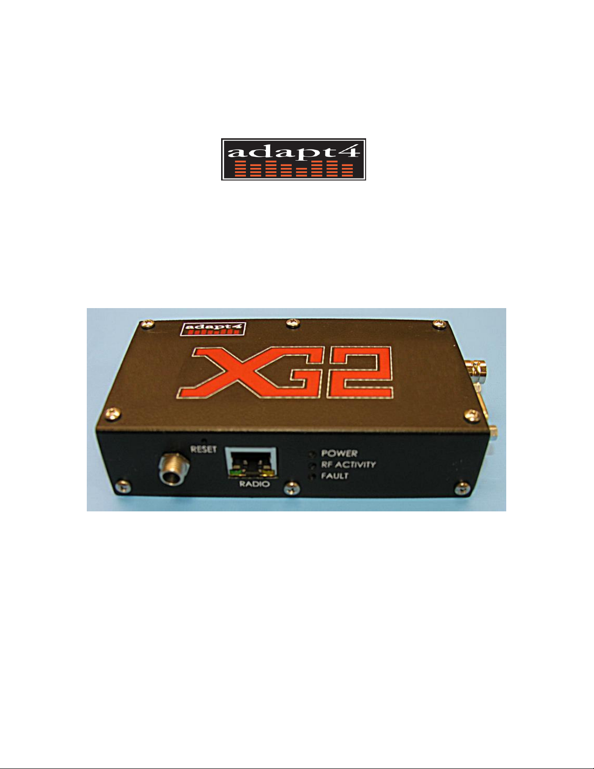
XG2/XG200 Radio
Installation Manual
A4-00171-001-01, Rev. 0.2c
Aug, 2007
Copyright © 2007 Adapt4, LLC
Page 2
Operational and Safety Warnings
Antenna Connection and Lightning Arrestor
The warranty requires that the radio must not be powered-up without an antenna
connected. The warranty also requires that a lightning arrestor be installed.
RF Exposure
The equipment described herein emits radio frequency (RF) energy and
requires professional installation. Although the power emitted is two
watts or less, care should be taken to use the radio equipment properly to
avoid the concentrated radio frequency energy near an antenna, especially a directional
antenna (for example, a yagi antenna). No person should be within 130 centimeters (53
inches) of the antenna when the radio is transmitting. This includes indoor, outdoor and
mobile use of the radio equipment.
FCC Part 15 Compliance
THIS DEVICE COMPLIES WITH PART 15 OF THE FCC RULES. OPERATION IS
SUBJECT TO THE CONDITION THAT THIS DEVICE DOES NOT CAUSE
HARMFUL INTERFERENCE.
NOTE: the manufacturer is not responsible for any radio or TV interference caused by
unauthorized modifications to this equipment. Such modifications could void the user’s
authority to operate the equipment.
2
Page 3
NOTICE
Adapt4, Inc. assumes no responsibility for any errors that may appear in this document, nor
does it make any commitment to update the information contained herein. However, questions
regarding the information contained in this document are welcomed.
Adapt4, Inc. also reserves the right to make changes to the specifications of the XG2 Series
and to the information contained in this document at any time without notice.
This manual is not all inclusive of our products and services. The software and procedures
discussed herein are continuously evolving just as are the requirements of our customers. Its
format is informal, and hopefully will stimulate as many questions as it answers. Copies of cut
sheets, engineering data, customer lists, installation guides, and test procedures are all available
for further information.
Adapt4, Inc,.
1050 W. NASA Blvd., Melbourne, FL 32901
Phone 321-872-6000 | Fax 321-872-6001
www.adapt4.com
3
Page 4

Table of Contents
Operational and Safety Warnings ................................................................................2
Table of Contents...........................................................................................................4
1 Overview......................................................................................................................5
1.0 Brief System Description ................................................................................................... 5
1.1 Front Panel Indicators and Connectors .............................................................................. 6
2 Installation...................................................................................................................8
2.0 Installation Process ............................................................................................................ 8
2.1 Connect laptop to radio ...................................................................................................... 8
2.2 Configure Radio ................................................................................................................ 9
2.3 Identity Page .................................................................................................................... 10
2.4 Serial Port Page ............................................................................................................... 10
2.5 Upload new firmware to radio ........................................................................................ 11
Appendix A. Configuring a Base Station .............................................................................. 12
4
Page 5

1 Overview
1.0 Brief System Description
The XG2 is a multi-mode radio for the SCADA, telemetry, framed-video surveillance and similar
applications for 10-200 kb/s communications. The XG2 operates in smart-serial, IP, mesh, and
DFS (Dataflow Systems compatibility) modes. The radio operates in several FCC-licensed bands,
depending on the model number. The factory-set bands include:
217-220 MHz
The XG2 contains a built-in field installation tool to configure the radio via a web browser,
typically on a laptop computer. The installation tasks that may be performed via the web browser
include the following::
• Radio configuration – channel center frequency, data rate/channel width, and operating mode.
• Network configuration – IP address of the radio.
• Port configuration – baud rate, frame format and serial protocol.
• Radio firmware update – update the radio firmware from files stored on the laptop.
Similarly, the above functions may be done over-the-air.
The above list of capabilities is a brief outline of the tasks of installing the radio. More details
will be given below.
Table 1.0-1 provides an equipment list needed to support XG2 Installation.
Table 1.0-1: Items Needed to Connect Radio to Computer
1. Laptop with:
• Windows 98 or later, Apple MAC or Linux operating system
• Ethernet port
• 128 MB RAM
• SVGA display or better
• Internet browser (Internet Explorer, Mozilla Firefox, Safari; others TBD)
2. Ethernet cable
• Cross-over (if directly connected), straight-through (if connected via hub)
Figure 1.0-1 illustrates an XG2 radio network, which is comprised of three XG2 radio Remote
Sites and a Base Station (Hub). The Remote Sites are further comprised of an antenna, the XG2
radio and end-user equipment. The end-user equipment is attached to the radio via Ethernet
and/or RS-232 serial cables.
The Base Station comprises an antenna (typically omnidirectional), an XG2 Base Station Radio,
Ethernet and optional RS-232 serial cabling from the radio into a shelter or building. These cables
5
Page 6
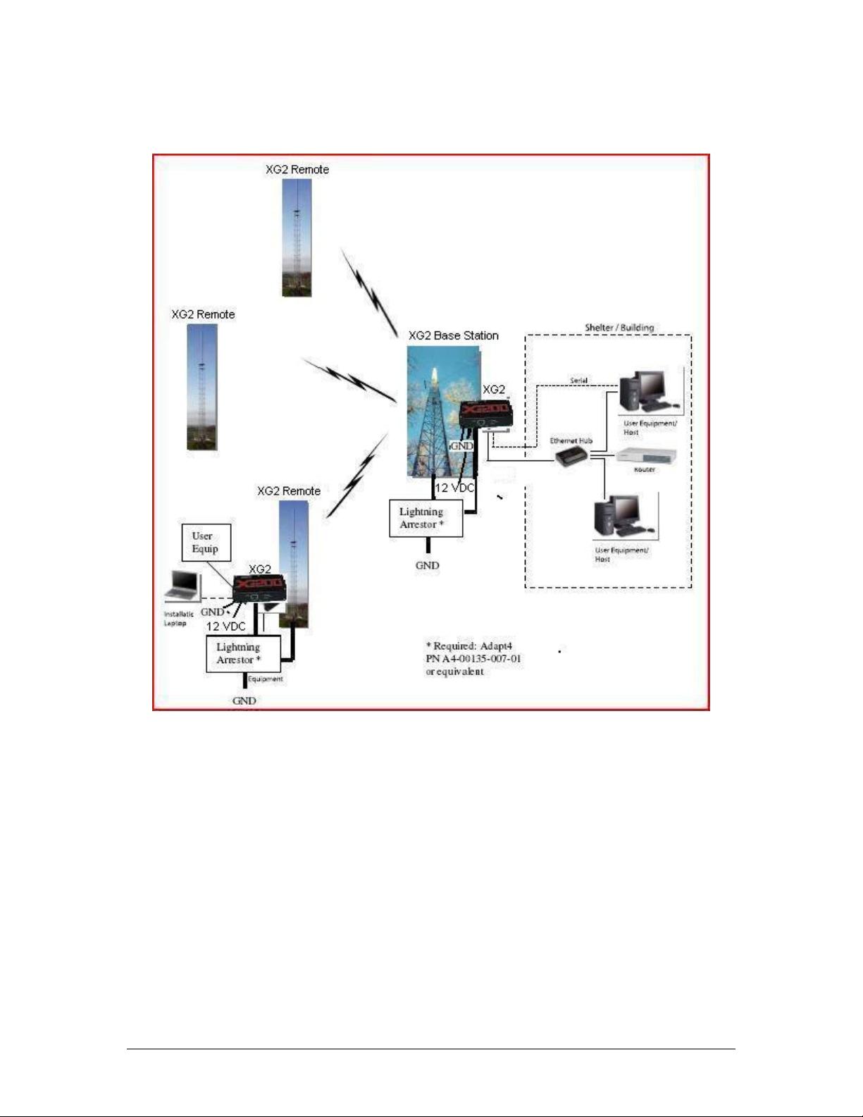
connect to user host equipment. In addition, the Ethernet cable allow connection to the XG2 radio
web page to Network Operators.
Figure 1.0-1: XG2 Radio Network
The XG2 radio must be installed in a weather-proof box, such as a NEMA box..
Warning: the radio was designed for mounting in a weather-proof box. Failure to
properly deploy the radio will void the warranty.
1.1 Front Panel Indicators and Connectors
Figure 1.1-1 and Table 1.1-1 illustrate and describe the front panel indicators and connectors of
the XG2.
6
Page 7
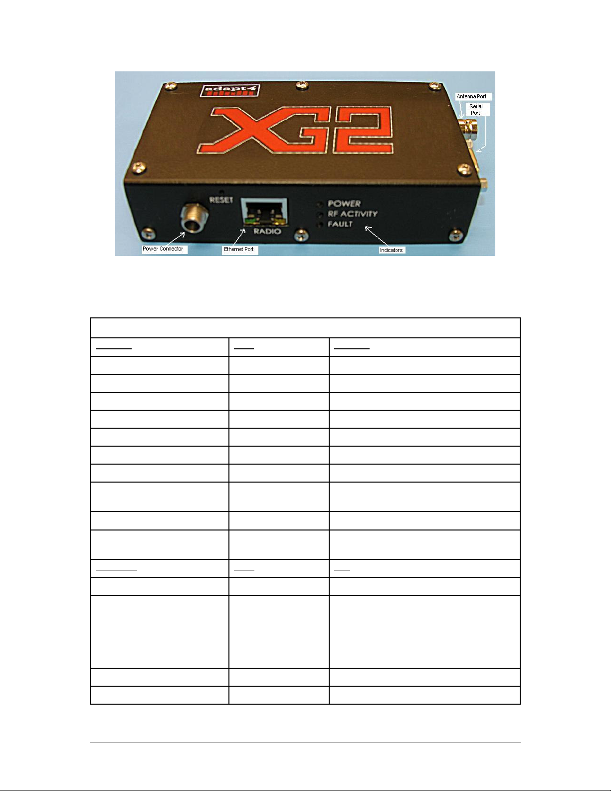
Figure 1.1-1 XG2 Front Panel Indicators and Connectors
Table 1.1-1: Front Panel Indicators and Connectors
Remote and Base Station Radio
Indicator State Meaning
Power LED Green The radio is powered
RF Activity LED Red/Flashing Packet transmitted over-the-air
Amber/Flashing Packet received over-the-air
Fault LED Green Radio is operational
Red Radio is faulted
RJ-45 Ethernet
--Green LED Dim solid Radio powering up
Flashing Transmitting on Ethernet port (from radio to
user device)
--Amber LED Solid Ethernet link indicator
Flashing Receiving on Ethernet port (from user device
to radio
Connector Type Use
Ethernet Connector RJ-45 User interface and radio configuration
Serial Port DB9-F RS-232 User interface
Pin 2: Rx Data
Pin 3: Tx Data
Pin 5: Signal Ground
Antenna Port BNC RF port for antenna
Power 12 VDC, Tx: 1.5A, Rx 0.3A
7
Page 8
2 Installation
2.0 Installation Process
The Field Installer installs XG2 radios using the steps described in sections 2.1 through 2.5. XG2
radios are shipped from the factory with setting appropriate for the customer. The most common
field changes will be frequency, node number, and IP address. The radio that will be used as the
base station requires additional configuration; see Appendix A.
2.1 Connect laptop to radio
Connect: The laptop communicates with the XG2 radio via an Ethernet cable. Use a crossover
cable for a direct connection or a straight-through cable via an Ethernet hub. You may have to set
your Ethernet port IP address to a static address so that you can talk to the radio. By default, the
radio's address is 10.255.0.1. As an example, you can set your laptop to 10.255.0.80 and set the
brower's URL to http://10.255.0.1. If the radio's IP address has been changed, you will similarly
set the laptop's IP address to an address in the same subnetwork. You can press the reset button
through a hole in the case as you apply power to set the IP address back to the default 10.255.0.1
until the next reset. Note: for Microsoft Windows computers, you change the IP address via the
Control Panel/Network Connections dialog.
Browse the radio: start the browser and connect to the radio web page. As described above, the
default URL is: http://10.255.0.1
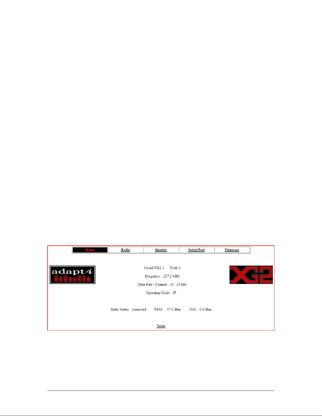
Login: the web page consists of four page links across the top: Home, Radio, Identity, Serial
Port and Firmware. See Figure 2.1-1. Click on one of the links to bring up the login screen. See
Figure 2.1-2. The default password is: admin with a blank user name
.
Figure 2.1-1 Home Page
8
Page 9
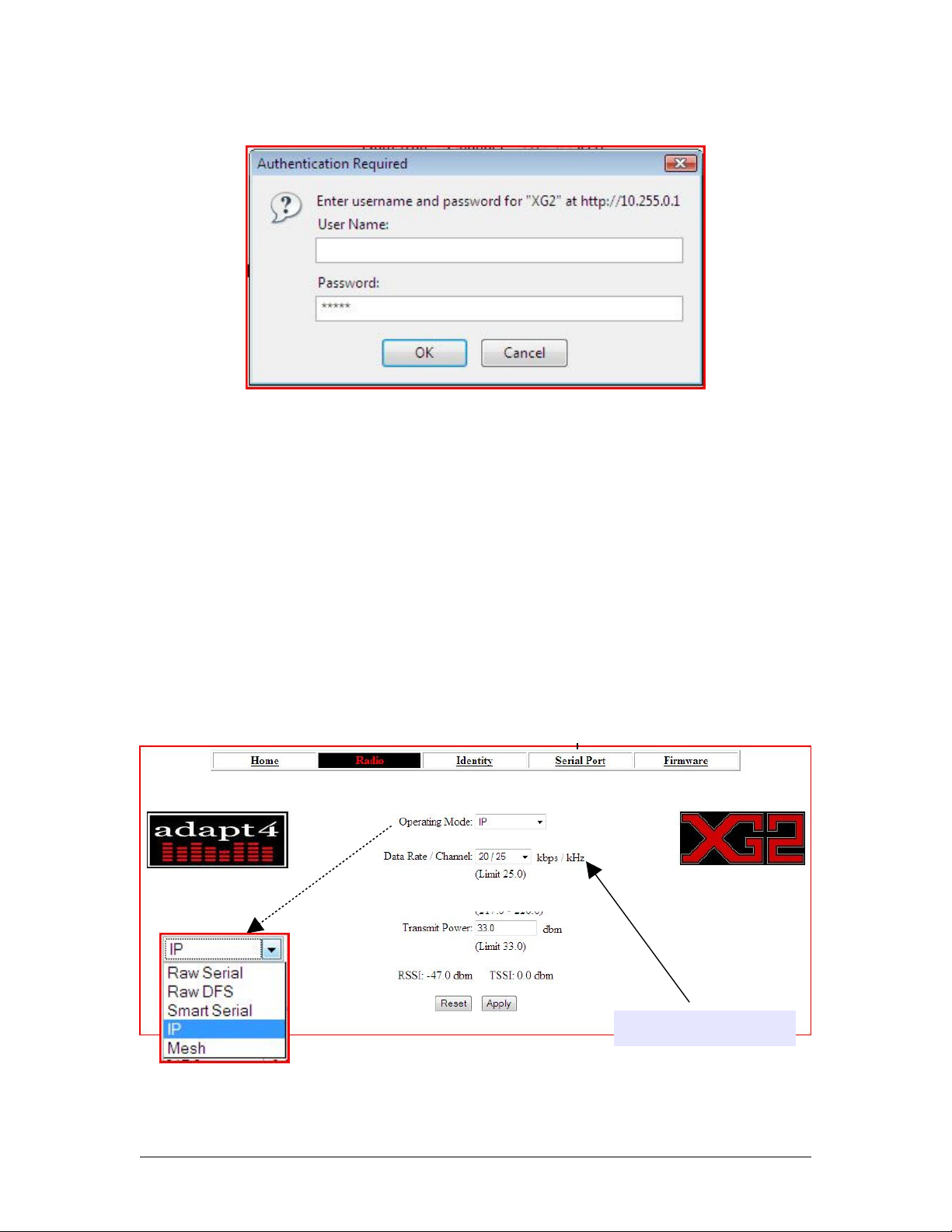
Figure 2.1-2 Login Pop-Up Window
2.2 Configure Radio
Click on the Radio link. See Figure 2.2-1. First, select the Operating Mode, using the dropdown menu. The contents of the menu are overlain on the lower right portion of the figure. The
Raw Serial selection is used only for bit-error-rate testing, not for user data. Raw DFS mode is
used for Data Flow Systems compatibility and is only available on XG200 models. (See the
XG200 application note.)
Smart serial requires the user equipment to control media access, i.e., when each radio takes its
turn to transmit. In IP mode, the XG2 radio acting as the base station controls media access.
Both smart serial and IP modes allow communication of serial data and IP (Ethernet) data. Mesh
mode is not yet available at this.
Important: all radios in a network must have the same operating mode, channel and frequency.
Only values applicable to
your model will be shown
Figure 2.2-1 Radio Configuration Page
9
Page 10
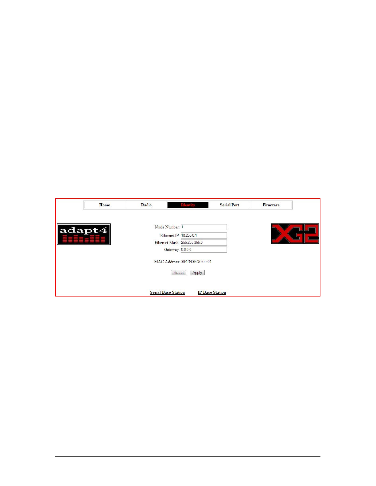
Data Rate/Channel: set the other-the-air data rate/channel rate via the drop-down menu. The
available values are shown in the overlay in the lower-right corner of the figure. The values are in
kilobits/sec and kilohertz. For example, the first selection is a 4.8 kb/s link with a 6.25 kHz
channel bandwidth. Frequency: select the center frequency of the desired FCC-licensed channel
in MHz. In the example given, the band is the 217-200 MHz band. Other bands will appear on
the screen for XG2 radios designed for other bands. The Transmit Power sets the desired
output power level in dBm; the range is limited to regulatory and radio limits..
2.3 Identity Page
Click on the Identity to set the XG2 radio's Node and IP address. See Figure 2.3-1. First, select
Node Number, which is an integer value determined by a network administrator. The Node
Number is a site ID. Select the site's IPv4 IP address and mask, also determined by a network
administrator, or 0 (zero) for automatic selection (DHCP). A common practice is to make the
node number identical to the last octet of the IP address. The Gateway is typically an IP address
of a network router at the Base Station, used to route packets on and off the network. The default
gateway is normally 0 except on the Base Station. The Serial Base Station and IP Base Station
links lead to screens used only if configuring the radio as a base station; see Appendix A.
Figure 2.3-1 Identity Page
2.4 Serial Port Page
Click on the Serial Port link. See Figure 2.4-1. This screen enables the setting of the serial port
setting. The Baud Rate drop-down menu selects baud rates from 4800 to 230400 bits/sec. The
frame parameters may be selected via radio buttons for 8 or 7 bits-length none/odd/even parity,
and one/two Stop Bits. Select the serial protocol using the Protocol drop-down menu, illustrated
in the lower right of the figure.
10
Page 11
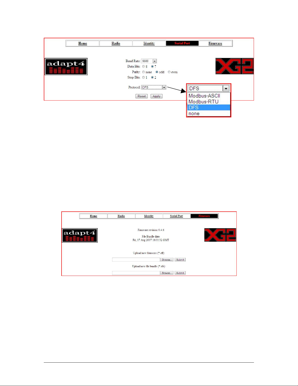
Figure 2.4-1 Serial Port Page
2.5 Upload new firmware to radio
Click on the Firmware link to display. See Figure 2.5-1. From this page, you can upload new
firmware and a new file bundle. Firmware is the radio's operational software. A File Bundle is a
collection of code and images comprising the radio's web page. The these items may be
downloaded from the http://download.adapt4.com web site. Browse to the firmware or file
bundle to upload and press Submit.
11
Figure 2.5-1 Firmware Page
Page 12
Appendix A. Configuring a Base Station
This appendix describes how to configure an XG2/XG200 as a base station (central station).
Refer to section 2.3 and figure 2.3-1 to see how to get to the base station configuration screens.
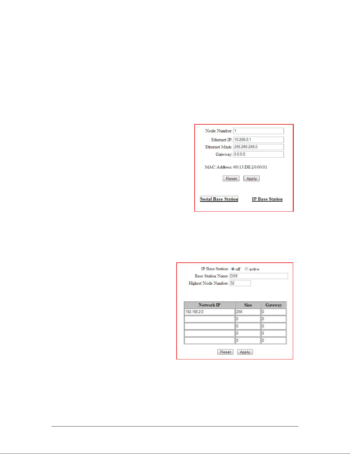
For serial base stations, click the Serial Base Station link link, which will display the screen
shown in Figure A1-1.
First, select Node Number, which is an integer value
determined by a network administrator. The Node
Number is a site ID. Select the site's IPv4 IP address
and mask, also determined by a network administrator,
or 0 (zero) for automatic selection (DHCP). A common
practice is to make the node number identical to the last
octet of the IP address. The Gateway is typically an IP
address of a network router at the Base Station, used to
route packets on and off the network. The default
gateway is normally 0 except on the Base Station. Click
the Apply button.
Figure A1-1 Serial Base Station
For IP base stations, click the IP Base Station link link, which will display the screen shown in
Figure A1-2. Fill in the Base Station Name and the Highest Node Number assigned to any
remote site.
For fixed networks, fill in the first row of the
table for the base station IP address (Network
IP), the Size of the network (the number of hosts
in the IP address, typically 256 for a Class D
network), and the Gateway IP address. Click the
Apply button.
For mobile networks (or any network with
multiple base stations), also fill an additional row
for each additional base station in the network.
Click the Apply button.
Figure A1-2 IP Base Station(s)
The Reset button may be used to clear the field entries.
12
Page 13

Adapt 4, Inc.
1050 W. NASA Blvd., Melbourne, FL 32901
Phone 321-872-6000 | Fax 321-872-6001
www.adapt4.com
13
 Loading...