

Adams Rite EX88-R313, EX88-M628, EX88-M335M, EX88-M335, EX88-M313M Installation Instructions
...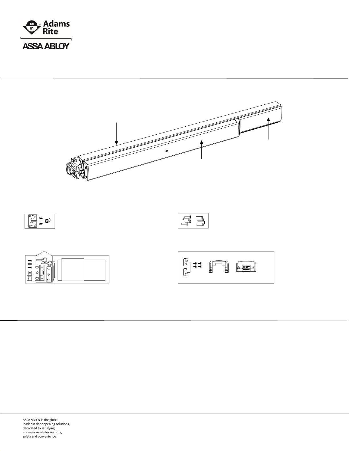
EX88 Interlocking Rim Exit Device
Box Contents
EX88 Interlocking Rim Exit Device
Cylinder and Trim Interface Kit
Mounting Hardware Kit
Frame Kit with Templates
Mounting End Cap Kit
Recommended Installation Tools
Safety glasses Measuring tape Level Pencil
Power drill Drill bits: 5/32”, 3/4” Center punch Phillips screw driver
Active Push Bar
Filler Plate
Back Bar
Preparation Guide and Installation Instructions
IMPORTANT NOTE 1: All work must be performed to applicable building, regulatory and lifesafety codes. Please consult local Authority Having Jurisdiction (AHJ) for more information.
IMPORTANT NOTE 2: The Americans with Disabilities Act (ADA) guidelines specify door
hardware be mounted 34”-48” above the finished floor.
Page | 1 P 800.872.3267 F 800.232.7329
E techsupport.adamsrite@assaabloy.com
www.adamsrite.com
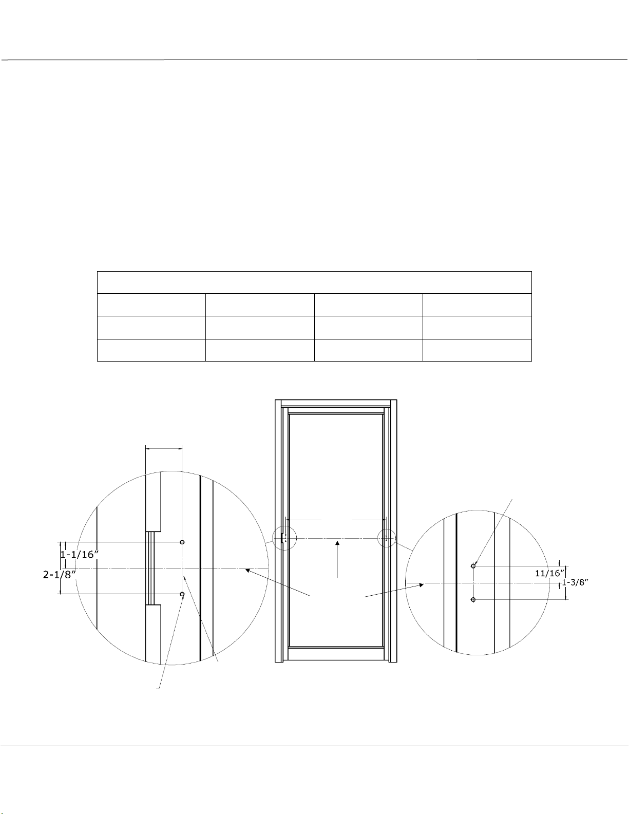
Preparing the Inside of the Door (LHR Shown)
1. DETERMINE and MARK the applicable bar height centerline (horizontal line) of the exit device on the
interior of the door.
2. DETERMINE the location of the latch end door template by using the bar height centerline of the exit
device and aligning the template with the mounting centerline (vertical line) of the door.
3. AFFIX the latch end door template to the door.
4. DETERMINE and MARK the hinge side preparation using dimension “A” as shown in the chart below.
5. IF standard door widths, as shown in the chart below, are not being used,
THEN CUT to proper length using Sizing the Exit Device chart on page 4.
6. MARK, CENTER PUNCH, DRILL all holes.
7. PREPARE door for cylinder and/or trim using Preparing the Door for Cylinder or Trim on page 5, if
required.
8. REMOVE the templates.
Standard Door Widths and Mounting Hole Spacing
Exit Device Length
Regular (R)
Midlength (M)
Long (L)
Standard Door
Opening Width
36”
42”
48”
Dimension “A”
33”
39”
45”
1-1/2” from
surface of strike
to mounting
centerline
Bar Height
Centerline
“A”
Mounting
Centerline
Drill 5/32”dia pilot
holes for self-tapping
screws, 2 places
Drill 5/32”dia pilot
holes for self-tapping
screws, 2 places
Page | 2 P 800.872.3267 F 800.232.7329
E techsupport.adamsrite@assaabloy.com
www.adamsrite.com
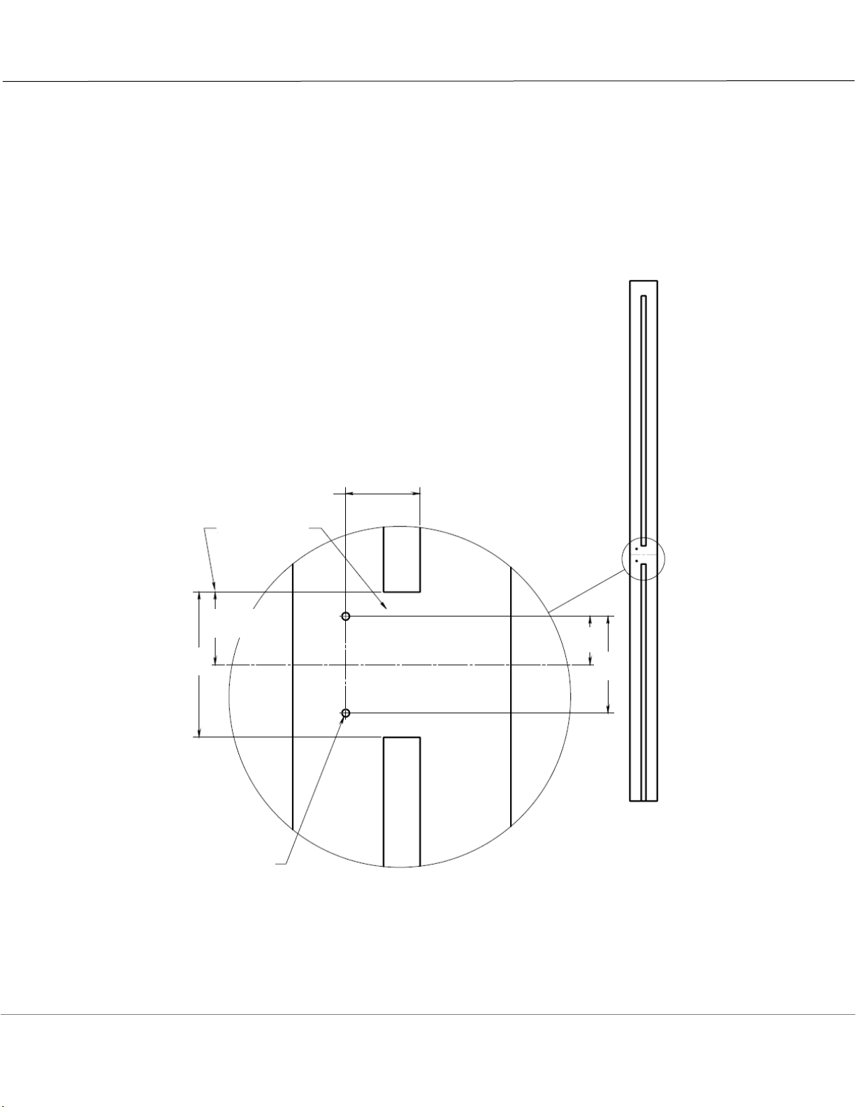
Prepping the Frame (LHR Shown)
1. DETERMINE and MARK the applicable bar height centerline (horizontal line) of the exit device on the
frame for the strike plate.
2. DETERMINE the location of the strike plate template by using the bar height centerline of the exit
device and aligning the template with the surface of the closed door.
3. MARK, CENTER PUNCH, DRILL all holes.
4. REMOVE the template.
1-17/32” from
inside surface
of closed door
Cut away
stop
Bar Height Centerline
1-1/2”
3”
1”
2”
Drill 5/32”dia pilot
holes for self-tapping
screws, 2 places
Page | 3 P 800.872.3267 F 800.232.7329
E techsupport.adamsrite@assaabloy.com
www.adamsrite.com
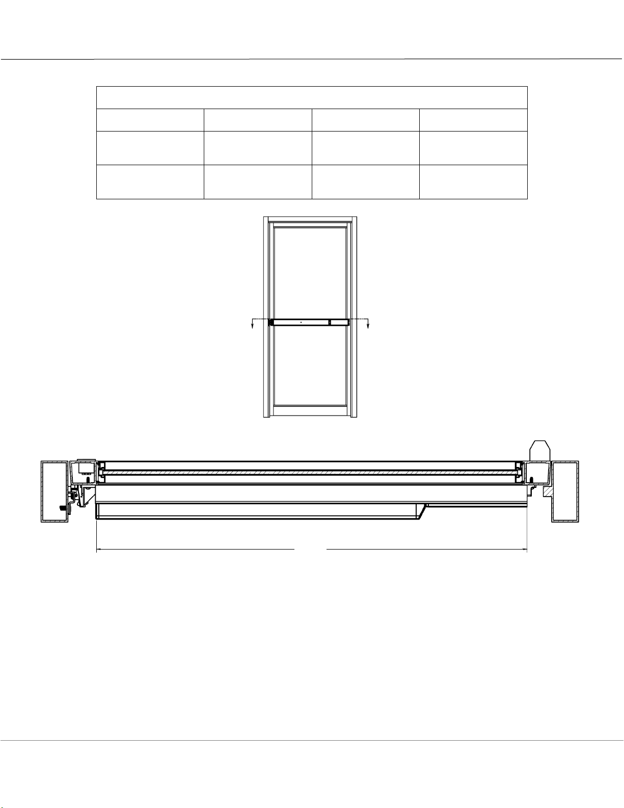
Sizing the Exit Device
Standard Door Widths and Mounting Hole Spacing
Exit Device Length
Regular (R)
Midlength (M)
Long (L)
Standard Door
Width
No Cut Required
36”
42”
48”
Minimum Door
Width Exit Device
Can Support
30”
30”
42”
NOTE: All EX Series Exit Devices are sized at the factory for 5/8” frame stop in narrow stile aluminum
applications.
1. DETERMINE cut off dimension “B” Back Bar extrusion length by subtracting 3-7/8” from door
opening width.
2. MARK cut off line “B” on Filler Plate and Back Bar.
3. REMOVE Filler Plate from Back Bar and CUT along lines on both pieces. REPLACE Filler Plate into
Back Bar.
IMPORTANT NOTE: Do not cut Active Push Bar
“B”
Page | 4 P 800.872.3267 F 800.232.7329
E techsupport.adamsrite@assaabloy.com
www.adamsrite.com

Preparing the Door for Cylinder or Trim
1. PREPARE the exterior and interior of the door for cylinder or trim using the latch end door template
and exterior cylinder template, as required.
2. PREPARE the door for cylinder mounting or trim mounting according to manufacturer’s instructions,
as required.
9/32”
Mounting
Centerline
Bar Height Centerline
Cylinder Centerline
Bar Height
Centerline
Bar Height
Centerline
1/4”
1/8”
13/16”
13/32”
3/8”dia
7/32”dia thru
c’sink 3/8”dia
x 82 deg, 2 plc
(cylinder only)
Exterior Preparation for Use with Cylinder
Interior Preparation for Use with Trim and Cylinder
Bar Height Centerline
Cylinder Centerline
1/8”
1-3/16”dia
(cylinder only)
Page | 5 P 800.872.3267 F 800.232.7329
E techsupport.adamsrite@assaabloy.com
www.adamsrite.com

Handing the Exit Device for Installation with
Cylinder or Trim
NOTE: The orientation of the trim plate differs for LHR and RHR applications. The Trim Actuator is
ALWAYS located on the bottom of the Trim Plate.
IF installing cylinder or trim,
THEN DETERMINE the door handing and INSTALL accompanying Cylinder and Trim Interface Kit
Left Hand Reverse – LHR
Right Hand Reverse – RHR
Page | 6 P 800.872.3267 F 800.232.7329
E techsupport.adamsrite@assaabloy.com
www.adamsrite.com

Installing the Exit Device
NOTE: Use provided self-tapping screws for aluminum or hollow metal applications.
Use provided wood screws for wood applications.
1. INSTALL Mounting Foot on hinge side of door
using two (2) #10-32 x 3/4” pan head screws.
Leave screws slightly loosened for final
adjustment.
2. SLIDE the exit device onto the mounting foot
3. INSTALL Interlocking Mounting Base on latch
side of door using two (2) #10-32 x 3/4” pan
head screws. Leave screws slightly loosened for
final adjustment.
Page | 7 P 800.872.3267 F 800.232.7329
E techsupport.adamsrite@assaabloy.com
www.adamsrite.com

Installing the Strike Plate
1. INSTALL the Strike Plates using two (2) #10-32
x 3/4” flat head screws.
2. VERIFY that exit device is fully operational.
3. ADJUST strike plate as necessary using shim
plates provided.
4. MARK, CENTER PUNCH, DRILL 5/32” diameter
pilot hole for center screw.
5. INSTALL the #10-32 x 3/4” flat head self-
tapping center screw to maintain optimum
adjustment.
10-32 x 3/4"
flat head selftapping
screws, 2 qty
10-32 x 3/4"
flat head selftapping screw,
1 qty
Page | 8 P 800.872.3267 F 800.232.7329
E techsupport.adamsrite@assaabloy.com
www.adamsrite.com

Testing and Adjusting Exit Device Operation
1. PERFORM a visual inspection to make certain exit device will be level and secure.
2. TEST the operation of the Active Push Bar and latching mechanism and ADJUST as necessary (door
should open when the Active Push Bar is depressed and properly lock into strike plate when door is
closed).
NOTE: The following is not applicable to fire-rated exit devices. Dogging the Active Push Bar disables
the latching function, making the door a simple push/pull operation.
3. DEPRESS and HOLD active push bar in unlocked position.
4. INSERT and ROTATE hex key one-quarter turn clockwise to lock device (DOG) into position.
5. ROTATE hex key one-quarter turn counterclockwise to unlock device and release device into
motion.
6. ENSURE exit device is operational and ADJUST as required.
NOTE: Over-rotation of the key past the prescribed one-quarter turn may cause damage to the exit
device.
3. TIGHTEN two (2) #10-32 x 3/4” pan head
mounting screws on the Mounting Foot on
hinge side of door.
4. TIGHTEN two (2) #10-32 x 3/4” pan head
mounting screws on the Interlocking Mounting
Base on latch side of door.
Page | 9 P 800.872.3267 F 800.232.7329
E techsupport.adamsrite@assaabloy.com
www.adamsrite.com

Installing the Mounting End Caps
1. INSTALL Hinge End Mounting End Cap on hinge
side of door using two (2) #8-32 x 3/8” tri lobe
pan head screws.
2. INSTALL Latch End Mounting End Cap on
latch side of door using two (2) #8-32 x 3/8”
tri lobe pan head screws.
Maintenance
1. CHECK mounting fasteners periodically and TIGHTEN if loose.
2. APPLY screw locking compound or CHANGE part fasteners if screws continue to back out.
3. PERFORM periodic and required checks and adjustments of strikes to compensate for wear and tear
such as door sagging.
Warranty
For complete warranty information, please visit the Adams Rite website:
http://www.adamsrite.com/en/site/adamsritecom/about/warranty/
Page | 10 P 800.872.3267 F 800.232.7329
E techsupport.adamsrite@assaabloy.com
www.adamsrite.com

Notes
Page | 11 P 800.872.3267 F 800.232.7329
E techsupport.adamsrite@assaabloy.com
www.adamsrite.com

adamsrite.com
800.872.3267
techsupport.adamsrite@assaabloy.com
80-0180-378 Rev 2
Copyright © 2017, Hanchett Entry Systems, Inc., an ASSA ABLOY Group company. All rights reserved.
Reproduction in whole or in part without the express written permission of Hanchett Entry Systems, Inc. is prohibited.
Page | 12 P 800.872.3267 F 800.232.7329
E techsupport.adamsrite@assaabloy.com
www.adamsrite.com
 Loading...