

Adams Rite EX88-R313, EX88-M628, EX88-M335M, EX88-M335, EX88-M313M Installation Instructions
...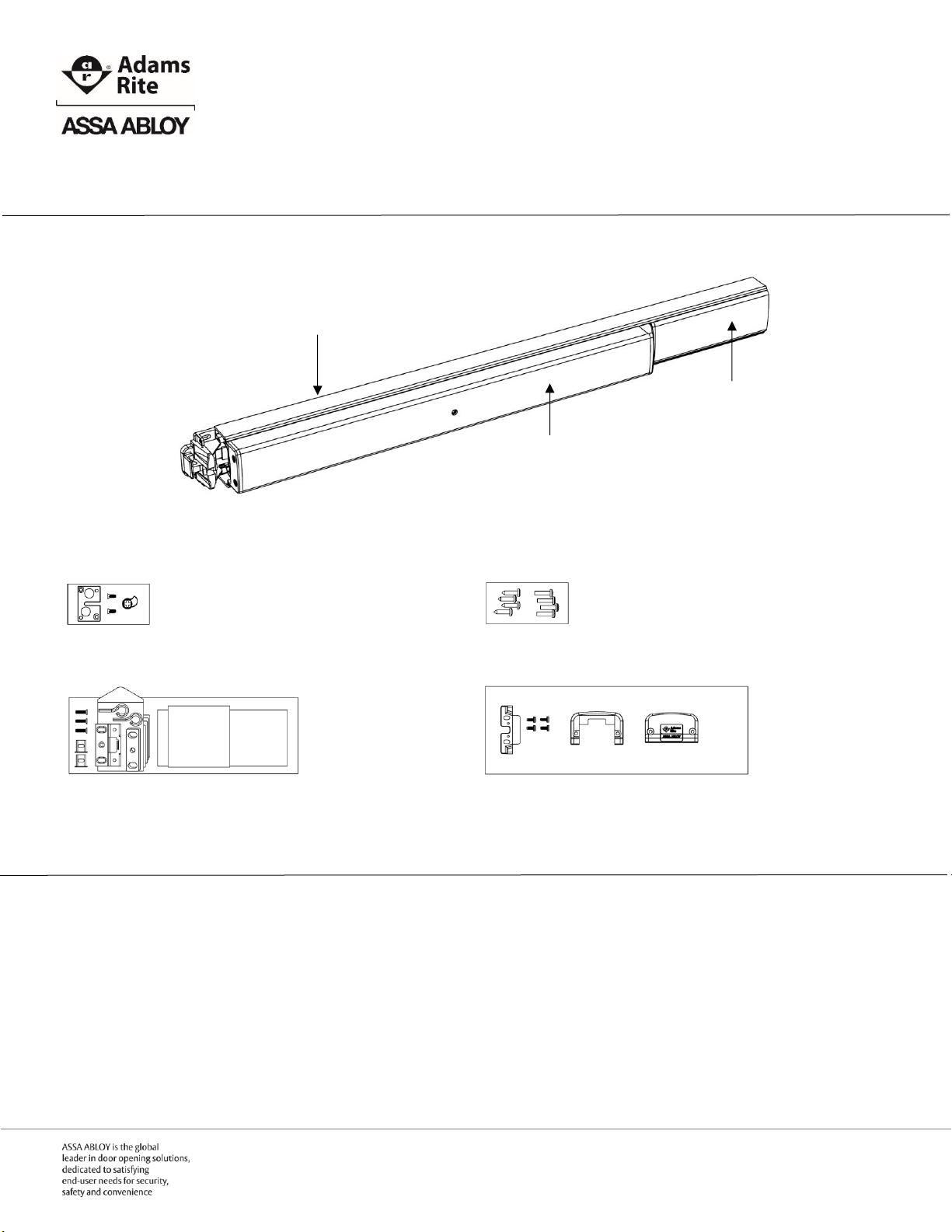
EX88 Interlocking Rim Exit Device
Box Contents
EX88 Interlocking Rim Exit Device
Cylinder and Trim Interface Kit
Mounting Hardware Kit
Frame Kit with Templates
Mounting End Cap Kit
Recommended Installation Tools
Safety glasses Measuring tape Level Pencil
Power drill Drill bits: 5/32”, 3/4” Center punch Phillips screw driver
Active Push Bar
Filler Plate
Back Bar
Preparation Guide and Installation Instructions
IMPORTANT NOTE 1: All work must be performed to applicable building, regulatory and lifesafety codes. Please consult local Authority Having Jurisdiction (AHJ) for more information.
IMPORTANT NOTE 2: The Americans with Disabilities Act (ADA) guidelines specify door
hardware be mounted 34”-48” above the finished floor.
Page | 1 P 800.872.3267 F 800.232.7329
E techsupport.adamsrite@assaabloy.com
www.adamsrite.com
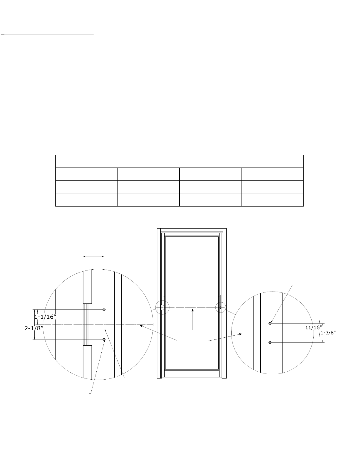
Preparing the Inside of the Door (LHR Shown)
1. DETERMINE and MARK the applicable bar height centerline (horizontal line) of the exit device on the
interior of the door.
2. DETERMINE the location of the latch end door template by using the bar height centerline of the exit
device and aligning the template with the mounting centerline (vertical line) of the door.
3. AFFIX the latch end door template to the door.
4. DETERMINE and MARK the hinge side preparation using dimension “A” as shown in the chart below.
5. IF standard door widths, as shown in the chart below, are not being used,
THEN CUT to proper length using Sizing the Exit Device chart on page 4.
6. MARK, CENTER PUNCH, DRILL all holes.
7. PREPARE door for cylinder and/or trim using Preparing the Door for Cylinder or Trim on page 5, if
required.
8. REMOVE the templates.
Standard Door Widths and Mounting Hole Spacing
Exit Device Length
Regular (R)
Midlength (M)
Long (L)
Standard Door
Opening Width
36”
42”
48”
Dimension “A”
33”
39”
45”
1-1/2” from
surface of strike
to mounting
centerline
Bar Height
Centerline
“A”
Mounting
Centerline
Drill 5/32”dia pilot
holes for self-tapping
screws, 2 places
Drill 5/32”dia pilot
holes for self-tapping
screws, 2 places
Page | 2 P 800.872.3267 F 800.232.7329
E techsupport.adamsrite@assaabloy.com
www.adamsrite.com
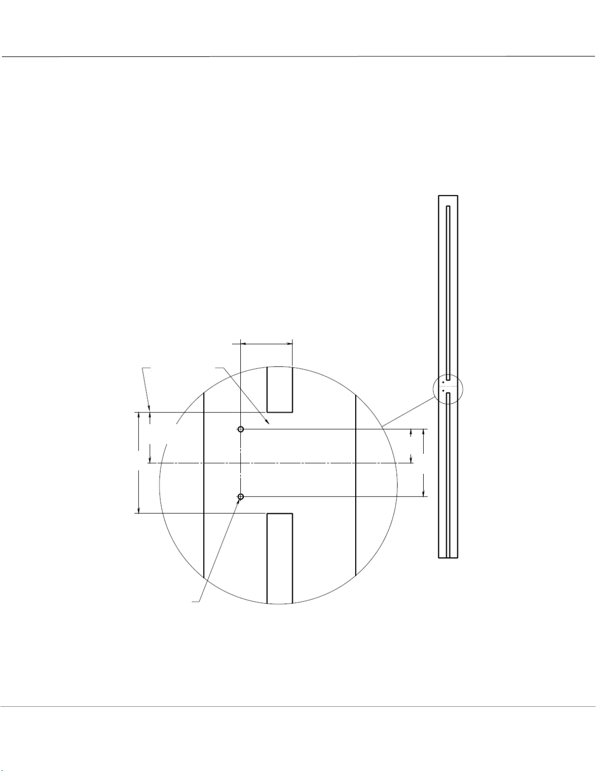
Prepping the Frame (LHR Shown)
1. DETERMINE and MARK the applicable bar height centerline (horizontal line) of the exit device on the
frame for the strike plate.
2. DETERMINE the location of the strike plate template by using the bar height centerline of the exit
device and aligning the template with the surface of the closed door.
3. MARK, CENTER PUNCH, DRILL all holes.
4. REMOVE the template.
1-17/32” from
inside surface
of closed door
Cut away
stop
Bar Height Centerline
1-1/2”
3”
1”
2”
Drill 5/32”dia pilot
holes for self-tapping
screws, 2 places
Page | 3 P 800.872.3267 F 800.232.7329
E techsupport.adamsrite@assaabloy.com
www.adamsrite.com
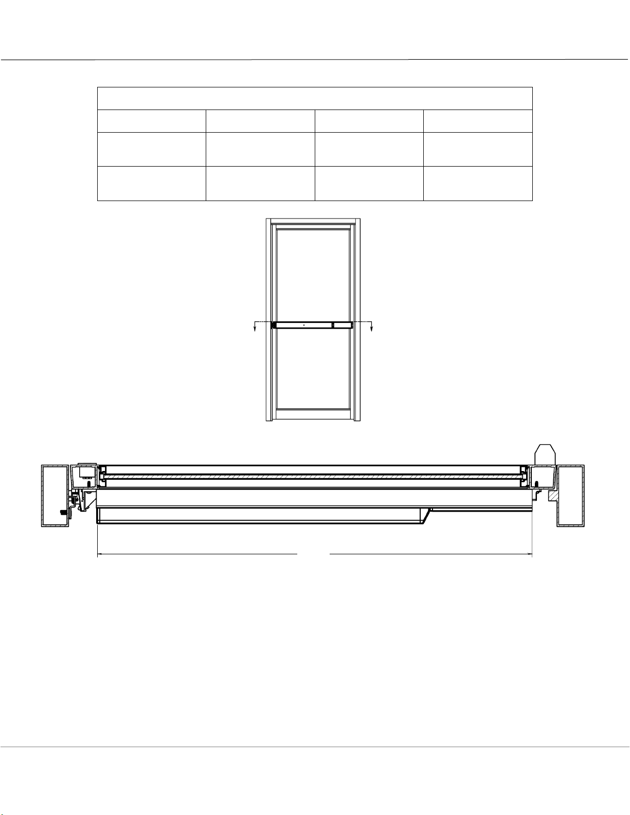
Sizing the Exit Device
Standard Door Widths and Mounting Hole Spacing
Exit Device Length
Regular (R)
Midlength (M)
Long (L)
Standard Door
Width
No Cut Required
36”
42”
48”
Minimum Door
Width Exit Device
Can Support
30”
30”
42”
NOTE: All EX Series Exit Devices are sized at the factory for 5/8” frame stop in narrow stile aluminum
applications.
1. DETERMINE cut off dimension “B” Back Bar extrusion length by subtracting 3-7/8” from door
opening width.
2. MARK cut off line “B” on Filler Plate and Back Bar.
3. REMOVE Filler Plate from Back Bar and CUT along lines on both pieces. REPLACE Filler Plate into
Back Bar.
IMPORTANT NOTE: Do not cut Active Push Bar
“B”
Page | 4 P 800.872.3267 F 800.232.7329
E techsupport.adamsrite@assaabloy.com
www.adamsrite.com
 Loading...