

Adams Rite EX76-L313, EX76-L313M, EX76-L335, EX76-L335M, EX76-L628 Installation Instructions
...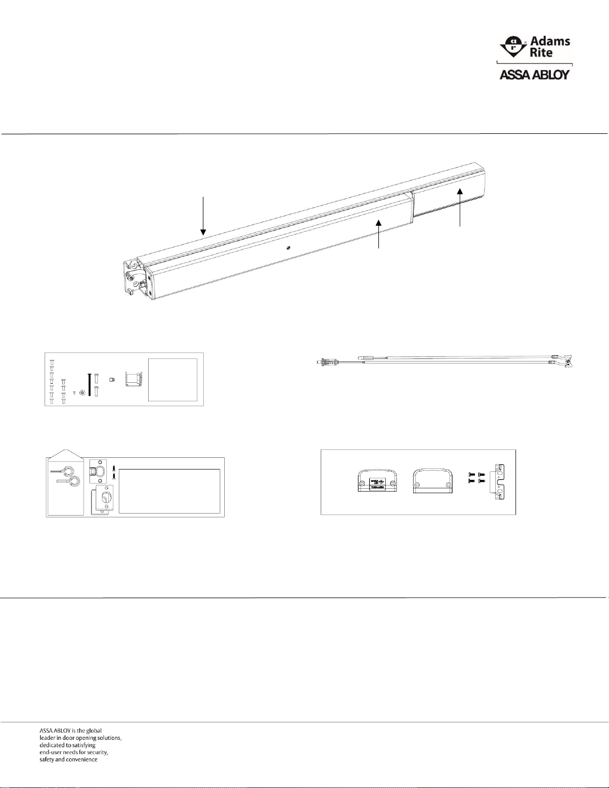
EX76 Concealed Vertical Rod Exit Device
Box Contents
EX76 Concealed Vertical Rod Exit Device
Door Kit with Templates
Rod Assembly
Frame Kit with Installation Instructions
Mounting End Cap Kit
Recommended Installation Tools
Safety glasses Measuring tape Level Pencil
Power drill Center punch Phillips screw driver Saw horse
Filler Plate
Back Bar
Active Push Bar
Preparation Guide and Installation Instructions
IMPORTANT NOTE 1: All work must be performed to applicable building, regulatory and lifesafety codes. Please consult local Authority Having Jurisdiction (AHJ) for more information.
IMPORTANT NOTE 2: The Americans with Disabilities Act (ADA) guidelines specify door
hardware be installed 34”minimum and 48” maximum above the finished floor.
Page | 1 P 800.872.3267 F 800.232.7329
E techsupport.adamsrite@assaabloy.com
www.adamsrite.com
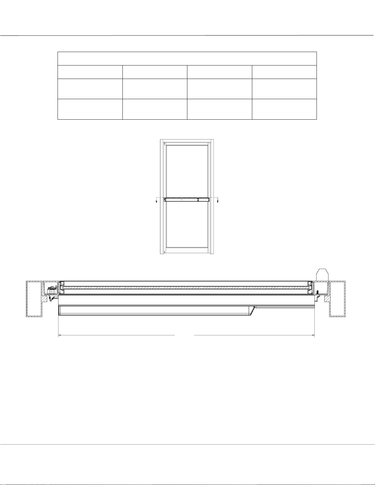
Sizing the Exit Device
Standard Door Widths and Mounting Hole Spacing
Exit Device Length
Regular (R)
Midlength (M)
Long (L)
Standard Door
Width
No Cut Required
36”
42”
48”
Minimum Door
Width Exit Device
Can Support
30”
30”
42”
NOTE: All EX Series Exit Devices are sized at the factory for 5/8” frame stop in narrow stile aluminum
applications.
1. DETERMINE cut off dimension “B” Back Bar extrusion length by subtracting 3-7/8” from door
opening width.
2. MARK cut off line “B” on Filler Plate and Back Bar.
3. REMOVE Filler Plate from Back Bar and CUT along lines on both pieces. REPLACE Filler Plate into
Back Bar.
IMPORTANT NOTE: Do not cut Active Push Bar
“B”
Page | 2 P 800.872.3267 F 800.232.7329
E techsupport.adamsrite@assaabloy.com
www.adamsrite.com
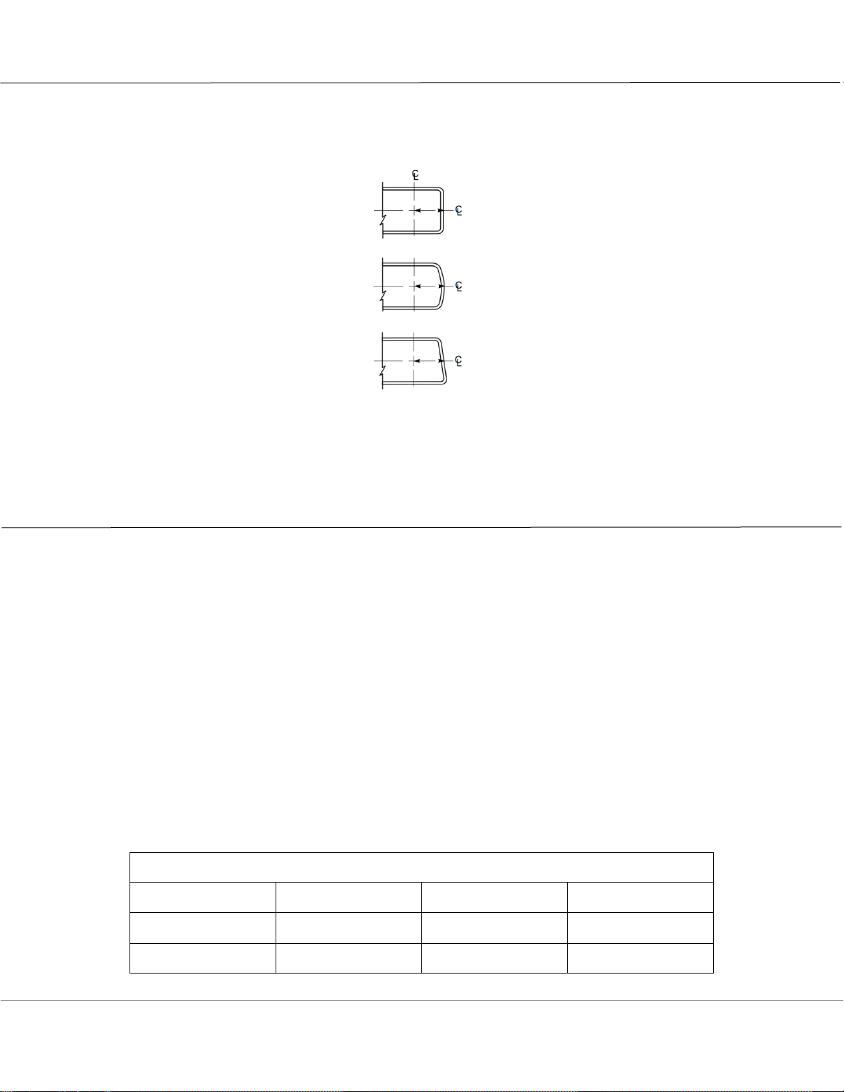
Measuring the Backset
NOTE: Backset is always measured at the door centerline, and not edge.
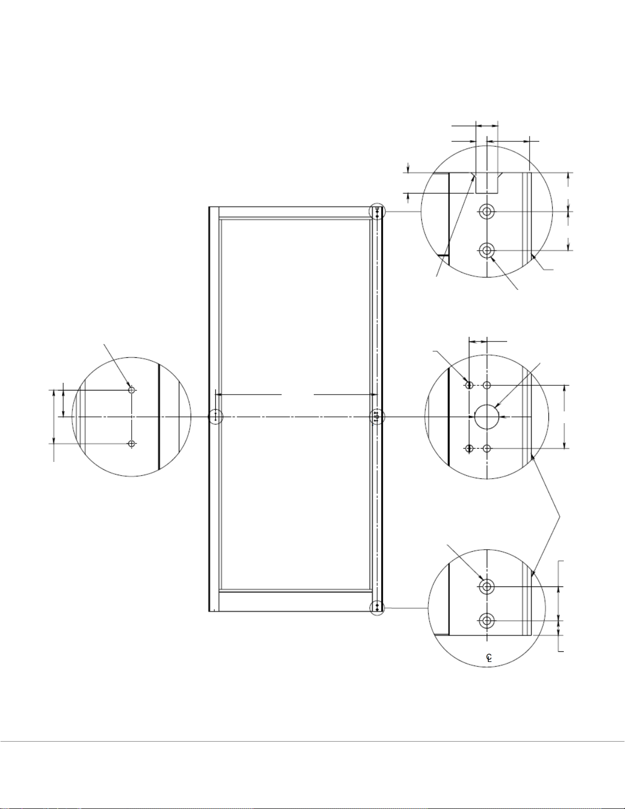
Preparing the Inside of the Door
1. DETERMINE and MARK the applicable bar height centerline (horizontal line) of the exit device on the
interior of the door.
2. DETERMINE and MARK the backset required.
3. DETERMINE the location of the door templates by using the bar height centerline of the exit device
and aligning the template with the backset centerline (vertical line) of the door. AFFIX the templates
to the door.
4. DETERMINE and MARK the hinge side preparation using dimension “A” as shown in the “Standard
Door Widths and Mounting Hole Spacing” chart below.
5. IF standard door widths, as shown in the “Standard Door Widths and Mounting Hole Spacing” chart
below are not being used,
THEN CUT to proper length using Sizing the Exit Device section on page 2.
6. MARK, CENTER PUNCH, DRILL all holes.
7. PREPARE door for cylinder escutcheon using “Preparing the Door for Mortise Cylinder Escutcheon” on
page 6, if required.
8. REMOVE the templates.
Standard Door Widths and Mounting Hole Spacing
Exit Device Length
Regular (R)
Midlength (M)
Long (L)
Standard Door
Opening Width
36”
42”
48”
Dimension “A”
33-¼”
39-¼”
45-¼”
Radius
Cylinder
Bevel
Flat
NOTE:
The backset required
by this CVR exit
device is 1-3/32”
Page | 3 P 800.872.3267 F 800.232.7329
E techsupport.adamsrite@assaabloy.com
www.adamsrite.com
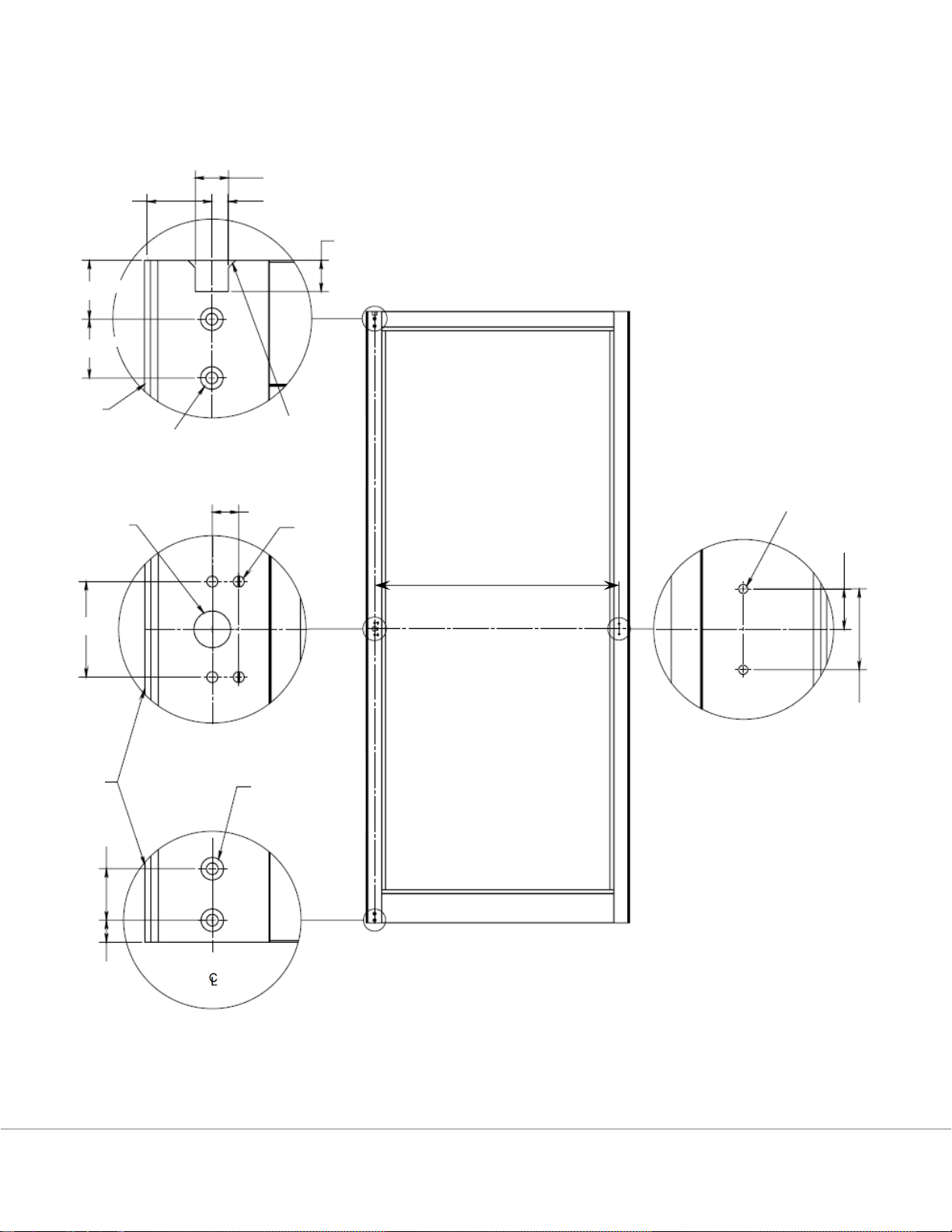
LHR Shown
Bar Height Centerline
“A”
Drill 5/32”dia pilot
holes for self-tapping
screws, 2 places
11/16”
9/16”
9/32”
1-3/32”
backset
17/32”
1”
1”
Lead
Edge
13/64" dia thru c'sink
25/64" dia x 82 deg,
2 places
1-3/8”
1/8” x 45
deg chamfer,
2 places
0.45”
3/16”
dia thru,
4 places
5/8” dia
thru
13/64” dia thru
c’sink 25/64”
dia x 82 deg, 2
places
Lead
Edge
1-5/8”
Backset
7/8”
NOTE:
The backset required
by this CVR exit
device is 1-3/32”
3/8”
Page | 4 P 800.872.3267 F 800.232.7329
E techsupport.adamsrite@assaabloy.com
www.adamsrite.com
RHR Shown
9/16”
9/32”
1-3/32”
backset
17/32”
1”
1”
1/8” x 45 deg
chamfer, 2
places
13/64" dia thru c'sink
25/64" dia x 82 deg,
2 places
Lead
Edge
0.45”
5/8” dia
thru
3/16”
dia thru,
4 places
1-5/8”
Lead
Edge
7/8”
3/8”
Backset
13/64” dia thru
c’sink 25/64” dia
x 82 deg, 2 places
NOTE:
The backset required
by this CVR exit
device is 1-3/32”
Bar Height Centerline
“A”
Drill 5/32”dia pilot
holes for self-tapping
screws, 2 places
11/16”
1-3/8”
Page | 5 P 800.872.3267 F 800.232.7329
E techsupport.adamsrite@assaabloy.com
www.adamsrite.com

Preparing the Door for Mortise Cylinder Escutcheon
1. PREPARE the exterior and interior of the door for mortise cylinder escutcheon using the latch end
door template and exterior cylinder template, as required.
2. PREPARE the door for mortise cylinder escutcheon mounting according to manufacturer’s
instructions, as required.
Bar Height
Centerline
Bar Height
Centerline
25/64” dia
x 82 deg
Lead
Edge
Exterior Preparation for Use with Mortise Cylinder
Escutcheon
Interior Preparation for Use with Mortise Cylinder
Escutcheon
Cylinder Centerline
Bar Height Centerline
Lead Edge
1”
1-3/8” dia thru
3/8” dia thru, 2 places
1/2”
1/4” dia thru all
3/4”
3/4”
1/4”
Page | 6 P 800.872.3267 F 800.232.7329
E techsupport.adamsrite@assaabloy.com
www.adamsrite.com
Installing the Exit Device
NOTE: Use provided self-tapping screws for aluminum or hollow metal applications.
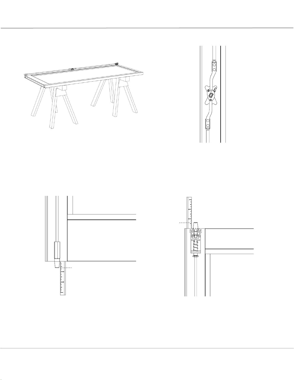
1. PLACE the door assembly on a saw horse with
the inside surface facing up.
2. PLACE the rod assembly on the face of the door
with the center block cylindrical portion aligned
with the installation hole.
3. EXTEND the rods fully.
4. ADJUST the bottom bolt for 5/8” projection from
the bottom of the door.
5. HOLD top bolt assembly with jam sensor inside
the notch. ADJUST top bolt for 5/8” projection
from the top of the door.
5/8”
5/8”
Page | 7 P 800.872.3267 F 800.232.7329
E techsupport.adamsrite@assaabloy.com
www.adamsrite.com

6. Being careful not to bend the rods, SLIDE rod
assembly through the top end of the latch stile
towards the center of the door until the bottom
bolt reaches the bottom of the stile.
7. ALIGN hex shape of bolt with hex shape of bolt
guide.
8. ATTACH the #8-32 x 2” helper screw
(provided) into the center block. PULL the
center block up into the installation hole.
9. While holding helper screw, SECURE center
block assembly to the latch stile with provided
#10-32 x 7/16” flat head screw.
10. Once secure, REMOVE and DISCARD the helper
screw.
11. SECURE the top latch assembly with two (2)
provided #10-32 x 7/16” flat head screws.
12. If necessary, DEPRESS the jam sensor to
release the top bolt on the top latch assembly.
13. ALIGN hex shape of bolt with hex shape of bolt
guide.
14. SECURE the lower attach point of bottom bolt
assembly with two (2) provided #10-32 x
7/16” flat head screws. This locks bottom bolt
into adjusted position.
#10-32 x 7/16”
flat head screw
#8-32 x 2”
pan head
helper screw
Jam
sensor
#10-32 x 7/16”
flat head screws
Lower attach
point of bottom
bolt assembly
#10-32 x 7/16”
flat head screws
Center
block
Page | 8 P 800.872.3267 F 800.232.7329
E techsupport.adamsrite@assaabloy.com
www.adamsrite.com

15. PLACE exit device onto stile, INSERT spindle into
drive hub.
16. SLIDE mounting foot into hinge side of back
bar. ENSURE that back bar is perpendicular to
vertical stiles of door.
17. MARK and CENTER PUNCH two (2) outer hole
positions through mounting foot.
18. REMOVE exit device, spindle and mounting foot.
DRILL two (2) holes in vertical stile using 5/32”
(#21, 0.159”) drill bit.
19. PLACE exit device onto stile, INSERT spindle into
drive hub.
20. SECURE exit device using two (2) provided #10-
32 x 7/16” flat head screws.
21. SECURE mounting foot using two (2) provided
#10-32 x 7/16” pan head screws.
Page | 9 P 800.872.3267 F 800.232.7329
E techsupport.adamsrite@assaabloy.com
www.adamsrite.com

Testing and Adjusting Exit Device Operation
1. PERFORM a visual inspection to make certain exit device will be level and secure.
2. TEST the operation of the Active Push Bar and the top and bottom bolts and ADJUST as necessary.
3. VERIFY that the top bolt retracts and latches, as appropriate.
4. VERIFY that the top and bottom bolts are flush with the door edges when retracted.
5. PUSH top jam sensor and VERIFY the top and bottom bolts project to 5/8” from the door edge.
6. IF bolts do not move,
THEN CHECK rods for binding.
NOTE: The following is not applicable to fire-rated exit devices. Dogging the Active Push Bar disables
the latching function, making the door a simple push/pull operation.
7. DEPRESS and HOLD active push bar in unlocked position.
8. INSERT and ROTATE hex key one-quarter turn clockwise to lock device (dog) into position.
9. ROTATE hex key one-quarter turn counterclockwise to unlock device and release device into
motion.
10. ENSURE exit device is operational and ADJUST as required.
NOTE: Over-rotation of the key past the prescribed one-quarter turn may cause damage to the exit
device.
Page | 10 P 800.872.3267 F 800.232.7329
E techsupport.adamsrite@assaabloy.com
www.adamsrite.com

Preparing the Header and Threshold
NOTE: Misalignment of mounting holes will prevent bolts from traveling into the deadlocked position.
1. POSITION door inside opening such that it is plumb and square, and door freely swings open.
INSTALL door according to manufacturer’s instructions.
2. MARK locations for bolt holes very carefully, allowing for weather stripping, if applicable.
3. MARK and DRILL 9/16” diameter center hole in threshold to receive bottom bolt.
To accommodate maximum bolt engagement, depth of hole in must be 3/4” deep, measured from top
of threshold and header.
4. MARK, CENTER PUNCH, DRILL 1” dia center hole in header to receive top bolt.
5. MARK, CENTER PUNCH, DRILL two (2) 1/8” dia holes in header to attach header strike.
6. The center point of the two (2) 1/8” dia holes must be symmetrical with the 1” dia hole centerline.
7. INSTALL header strike plate using included #6 x 1/2” self-tapping Phillips flat head screws and shim
plates, as required.
Two (2) 1/32” and two (2) 1/16” shim plates are included to mount between header strike plate and
frame, as required, in order to maintain no more than 1/8” gap between top of door and header strike
plate.
ENSURE gap between top of door and header strike plate is no more than 1/8”.
8. INSTALL header strike plate using included #6 x 1/2” self-tapping Phillips flat head screws and shim
plates, as required.
9. CLOSE door. VERIFY proper operation of door and exit device. ADJUST as required.
Minimum 1/4" applied or fixed
stop required at the frame top
1/8” dia mounting holes, 2 places
1” dia center hole
1-9/16”
Header strike plate installed with curved
feature positioned towards the outside
#6 x 1/2" self-tapping screws
1/32” shim plates
1/16” shim plates
Page | 11 P 800.872.3267 F 800.232.7329
E techsupport.adamsrite@assaabloy.com
www.adamsrite.com

Adjusting the Bolts
The following steps address how to adjust bolts for proper engagement with the header and threshold for
varying installed door gaps.
Top Bolt
1. MEASURE the door gap at the header. ADD 1/2” to this measurement to a maximum allowable
adjustment of 5/8”.
2. PUSH in active push bar to retract top bolt. OPEN door.
3. ADJUST top bolt by pushing it inwards and rotating clockwise or counterclockwise until the released
projection equals the measurement calculated in Step 1.
The bolt projection will change 1/8” for every 3 full rotations of the bolt.
4. ALIGN hex shape of top bolt with hex shape of bolt guide.
CLOSE door. VERIFY proper operation of door and exit device. ADJUST as required.
Page | 12 P 800.872.3267 F 800.232.7329
E techsupport.adamsrite@assaabloy.com
www.adamsrite.com

Bottom Bolt
1. MEASURE the door gap at the threshold. ADD 1/2” to this measurement to a maximum allowable
adjustment of 3/4”.
2. PUSH in active push bar to retract bottom bolt.
3. LOOSEN top mounting screw of bottom bolt guide. OPEN door.
4. ADJUST bottom bolt by rotating it clockwise or counterclockwise until the released projection equals
the measurement calculated in Step 1.
The bolt projection will change 1/8” for every 3 full rotations of the bolt.
5. ENSURE the flat side of hex bolt and bolt guide are parallel to the inner stile face.
6. TIGHTEN top mounting screw of bottom bolt guide.
7. CLOSE door. VERIFY proper operation of door and exit device. ADJUST as required.
Page | 13 P 800.872.3267 F 800.232.7329
E techsupport.adamsrite@assaabloy.com
www.adamsrite.com

Installing the Mounting End Caps
1. INSTALL hinge side mounting End Cap on hinge
side of door using two (2) #8-32 x 3/8” tri lobe
pan head screws.
2. INSTALL latch side mounting End Cap on
latch side of door using two (2) #8-32 x 3/8”
tri lobe pan head screws.
Maintenance
1. CHECK mounting fasteners periodically and TIGHTEN if loose.
2. APPLY screw locking compound or CHANGE part fasteners if screws continue to back out.
3. PERFORM periodic and required checks and adjustments of strikes to compensate for wear and tear
such as door sagging.
Warranty
For complete warranty information, please visit the Adams Rite website:
http://www.adamsrite.com/en/site/adamsritecom/about/warranty/
Page | 14 P 800.872.3267 F 800.232.7329
E techsupport.adamsrite@assaabloy.com
www.adamsrite.com

Notes
Page | 15 P 800.872.3267 F 800.232.7329
E techsupport.adamsrite@assaabloy.com
www.adamsrite.com

adamsrite.com
800.872.3267
techsupport.adamsrite@assaabloy.com
80-0180-270 Rev 2
Copyright © 2017, Hanchett Entry Systems, Inc., an ASSA ABLOY Group company. All rights reserved.
Reproduction in whole or in part without the express written permission of Hanchett Entry Systems, Inc. is prohibited.
Page | 16 P 800.872.3267 F 800.232.7329
E techsupport.adamsrite@assaabloy.com
www.adamsrite.com
 Loading...