

Page 1
version 1.0
Page 2

This safety manual must be read by all that will operate the SpekTrix system, prior to use. The Adamson SpekTrix
systems should not, under any circumstance, be operated by those who have not studied this manual. Supervision
and competency are the responsibility of the system owners and operators. Owners and operators are responsible
for inspecting the rigging and ensuring that it has not been damaged in transport, from misuse, or wear and tear. All
welded intersections and joints, on the rigging frames, should be inspected regularly. Operators should not assume that
the rigging has been inspected prior to use.
RIGGING
Correct use of all rigging hardware is required for safe use of this product. All rigging of this
product must be done by a certified rigger. All users must read the SpekTrix User Manual and
heed all warnings within, before use of this product.
SAFETY FACTOR
This product has an 8:10 Safety Factor. Any additional modules hung from this assembly will
result in a reduction of the factor of safety of the lifting frame below that which is required.
LOUD NOISE
A qualified technician must be present during the installation and use of this product. This
product is capable of producing extremely high sound pressure levels (SPL), and should be
used according to specified local sound level regulations and good judgment. The SPL
generated by this product may cause permanent hearing loss if used incorrectly.
MAINTENANCE
Before use of this product, all enclosure components including rigging must be thoroughly
inspected for cracks, corrosion, deformation, or any other damage that could reduce the
strength or safety of the array, by an expert trained and experienced in flying Adamson
speaker systems.
PINCH FACTOR
This product and its rigging system has possible pinch points, all of which are shown in the User
Manual. Make note of all possible pinch hazards before use.
DISCLAIMER
Adamson Systems Engineering will not be held liable for damages caused by any possible
misuse of this product.
Page 3

Warning
Read carefully before starting
p. 2
Section 1
1.1) Introduction to SpekTrix p.4
1.2) Product Line p. 4-5
1.3) What’s inside the SpekTrix p. 6-7
1.4) Rigging Hardware p.8-11
1.5) Accessories p.12-14
1.6) Specifications:
SpekTrix p. 15-19
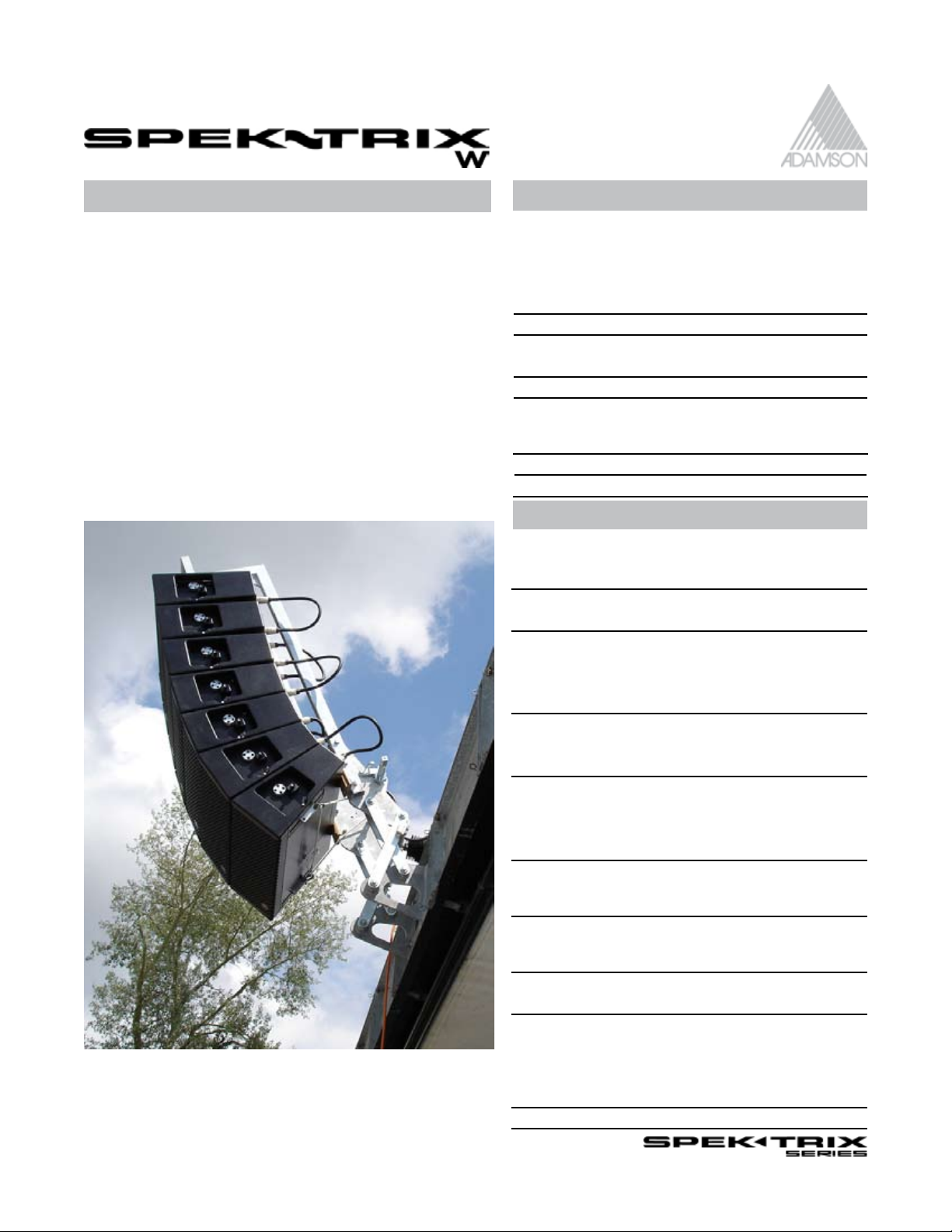
SpaekTrix W p. 20 -21
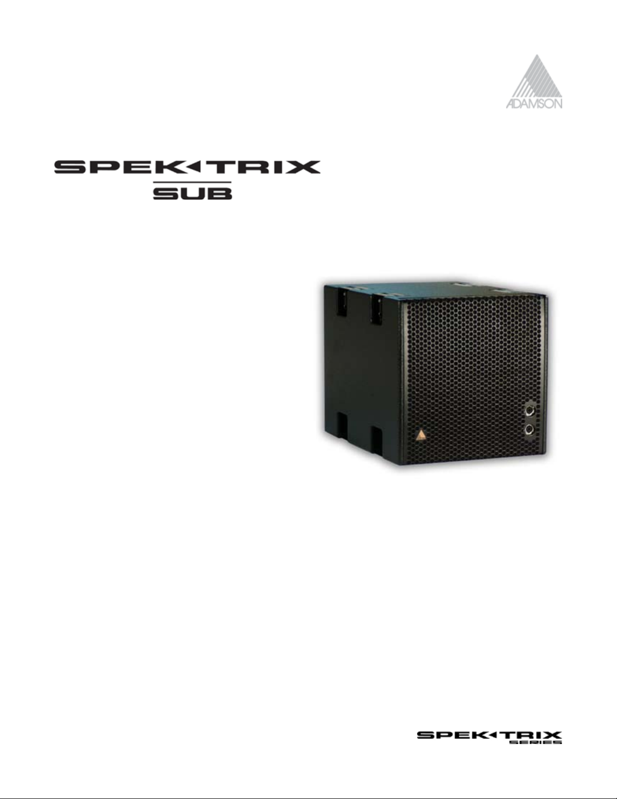
SpekTrix Sub p. 22-23
Section 2
2.0) Designing a project p. 24
2.1) Shooter Software p. 25
2.2) Shooter Quick Start Guide p. 26-31
Section 3
3.0) Total System Approach p. 32
3.1) Turnkey Solutions p. 33
3.2) Pin Configuration Table p. 34
3.3) Amp & Pin Configurations p. 35
3.4) Presets for Processors p. 36
Section 4
4.0) Rigging & Cabling Instructions p. 37
4.1) Precautions p. 37
4.2) Flying the Array p. 38-45
4.3) Ground Stacking the Array p. 46
4.4) Rigging Certificate p. 47
Section 5
5.0) Configuration Examples p. 48-71
SpekTrix Series User Manual 3 of 72
Page 4
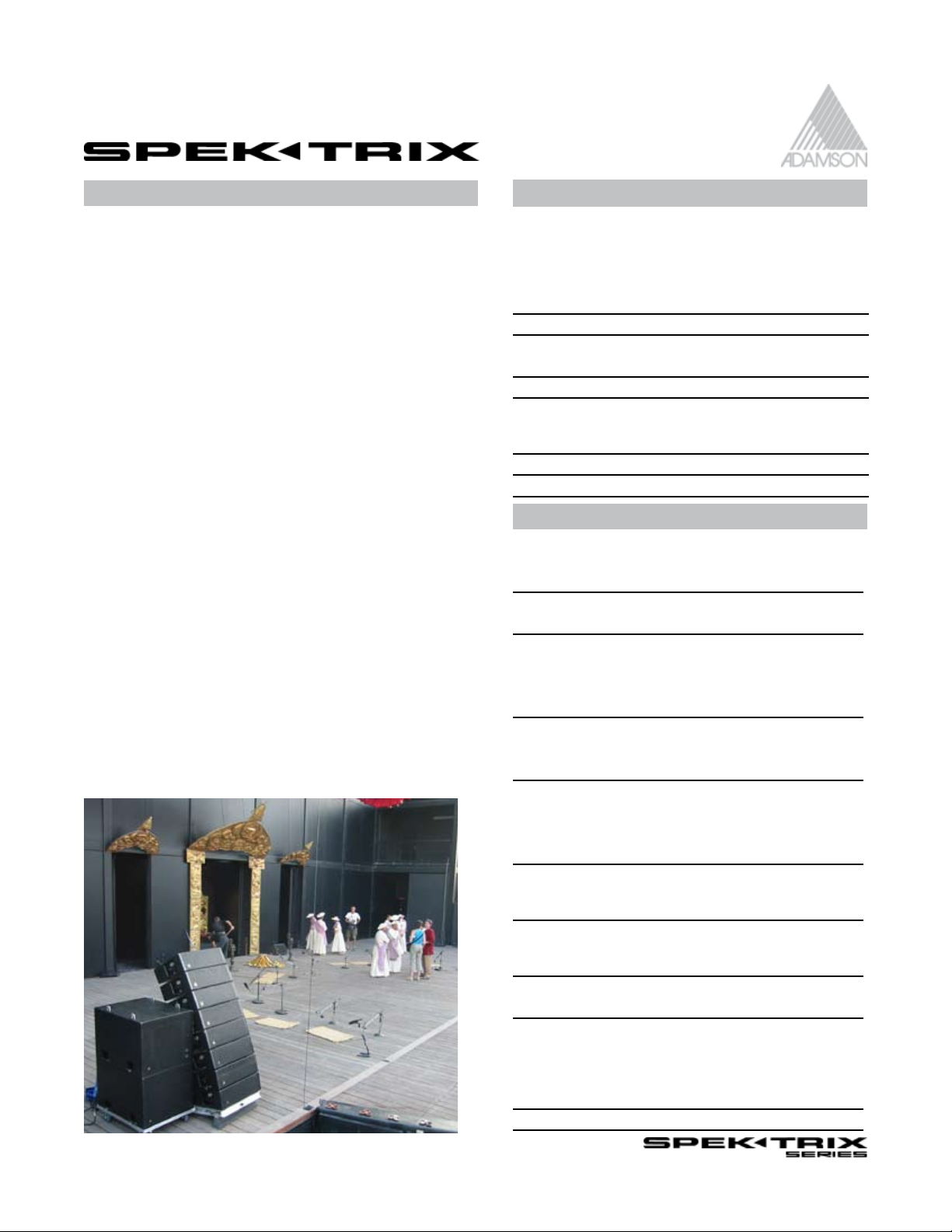
1.1 Introduction
This manual is designed to help SpekTrix users to correctly rig and understansd the priciples & versatility behind
the SpekTrix True Line Source Array. The Adamson SpekTrix Series offers all the benefits of a true line-source array
via patented wave shaping sound chamber technology.
1.2 Product Line
Product Code:
900042
Description:
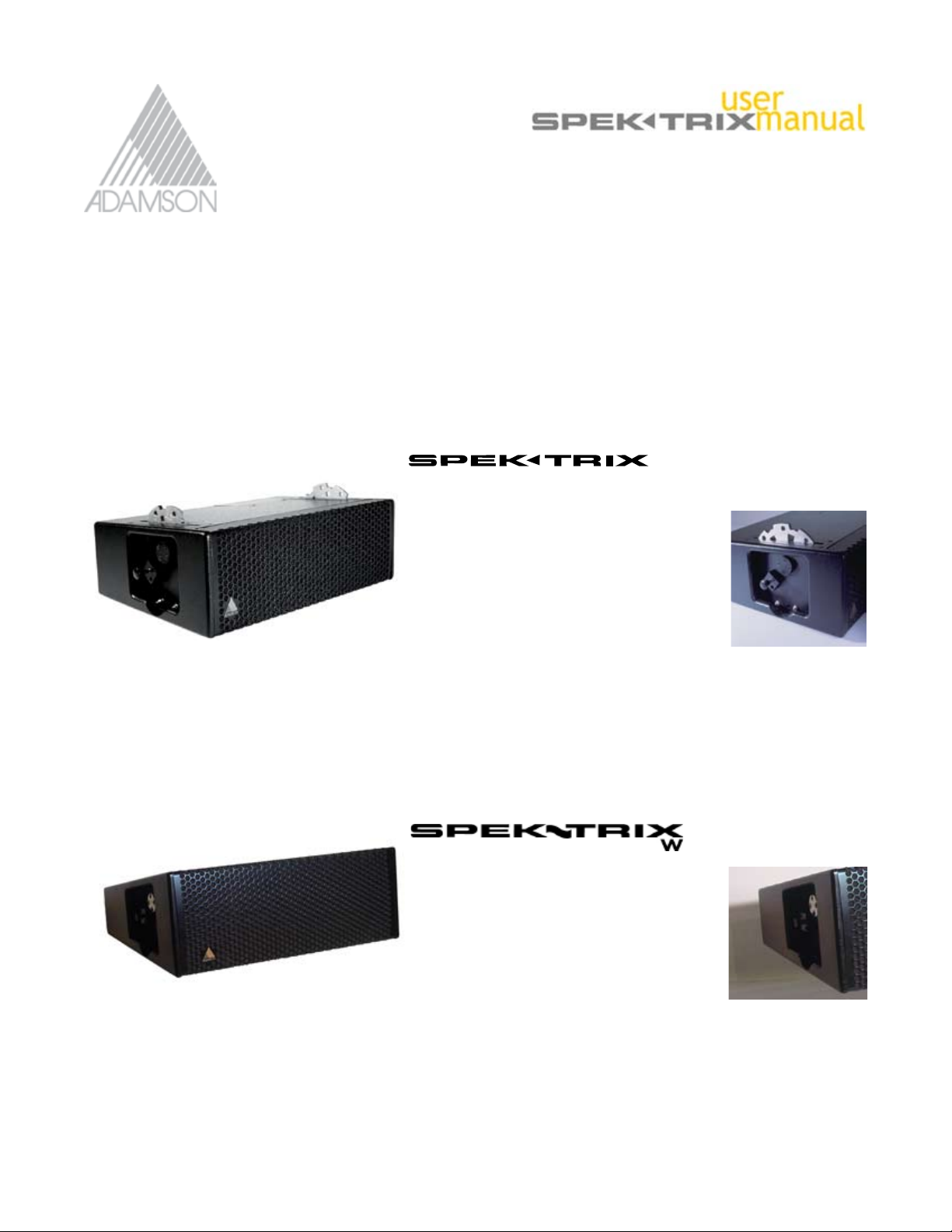
SpekTrix is a three-way cabinet that exhibits extremely high output for a compact box. The enclosure incorporates
two unique Adamson 8.5” Kevlar, neodymium drivers - one ND8-L midbass driver and one ND8-M mid-range
driver, and one B&C DE 900 compression driver mounted on a patented Adamson wave shaping sound
chamber. The sound chamber has a defined coverage pattern of 5-degrees V by 120-degrees H, and is similar
to the inner body of a Y-Axis drive module, giving the SpekTrix a slightly curved, iso-phase wave front comparable
to that of the Y-Axis system.
Product Code:
900041
Description:
The 15-degree trapezoidal cabinet design makes it easy to achieve extreme downward angles at the bottom
of an array, ensuring optimal coverage in the front rows and is perfect for use in wide vertical coverage array
designs. Both SpekTrix and SpekTrix W are 3-way enclosures.
SpekTrix Series User Manual 4 of 72
Page 5
1.2 Product Line
Product Code:
900043
Description:
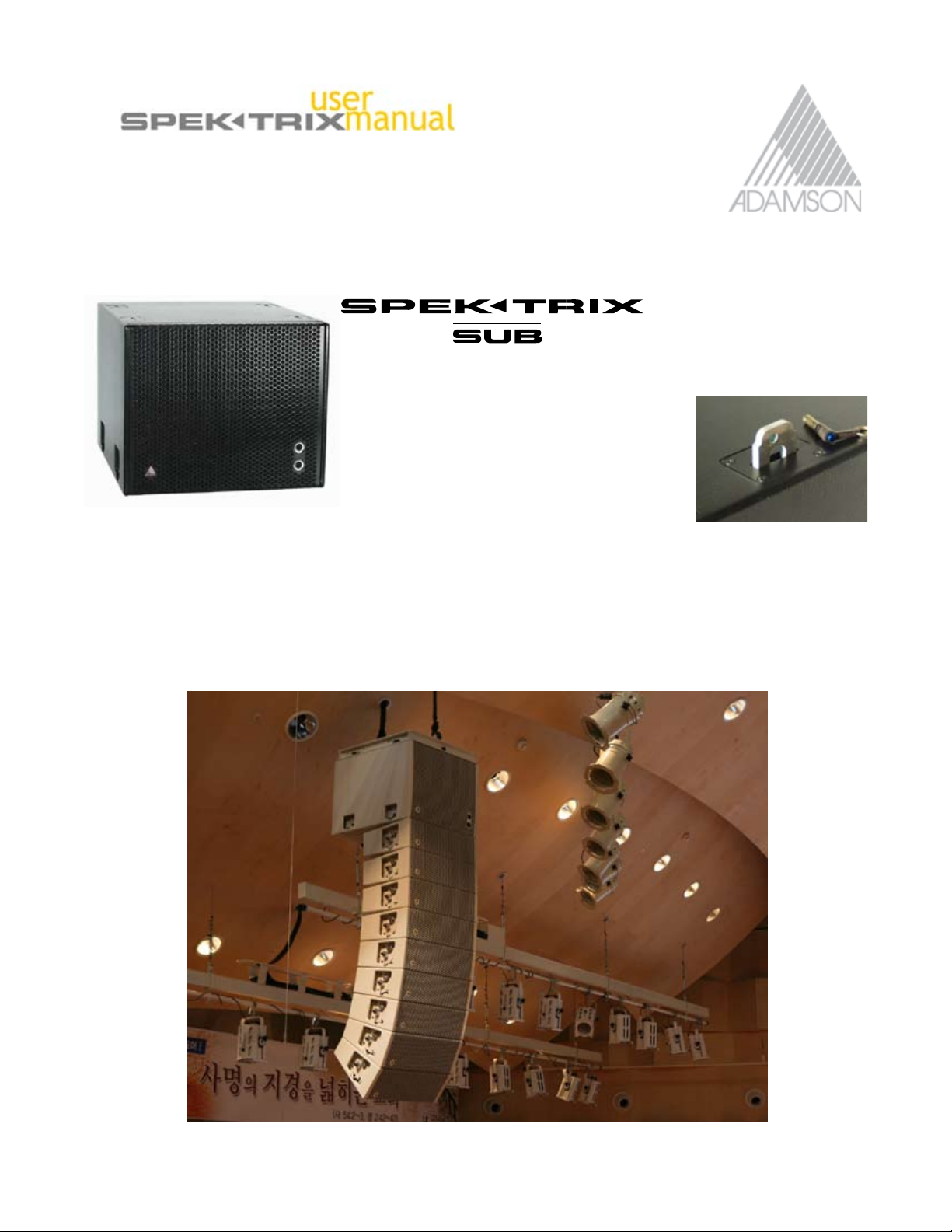
the SpekTrix Sub is the first Adamsonenclosure to introduce Convertible Cardioid Technology, and is a singlesided box that can be arrayed conventionally (all facing the same way) or can be arrayed in back-to-front pairs
for true cardioid performance.
The SpekTrix Sub is equipped with two powerful AW18 Kevlar LF drivers mounted in a tuned, vented and fully
braced cabinet.
SpekTrix Series User Manual 5 of 72
Page 6
1.3 What’s Inside the SpekTrix?
SpekTrix W’s components are exactly the same as the SpekTrix Enclosure’s, except for its HF sound chamber,
which is distinct in order to attain its 15 degrees of vertical coverage.
The SpekTrix Sub features Two Adamson AW18 LF Drivers, which are manifold loaded.
Product Code:
8600004
SpekTrix Series User Manual 6 of 72
Page 7
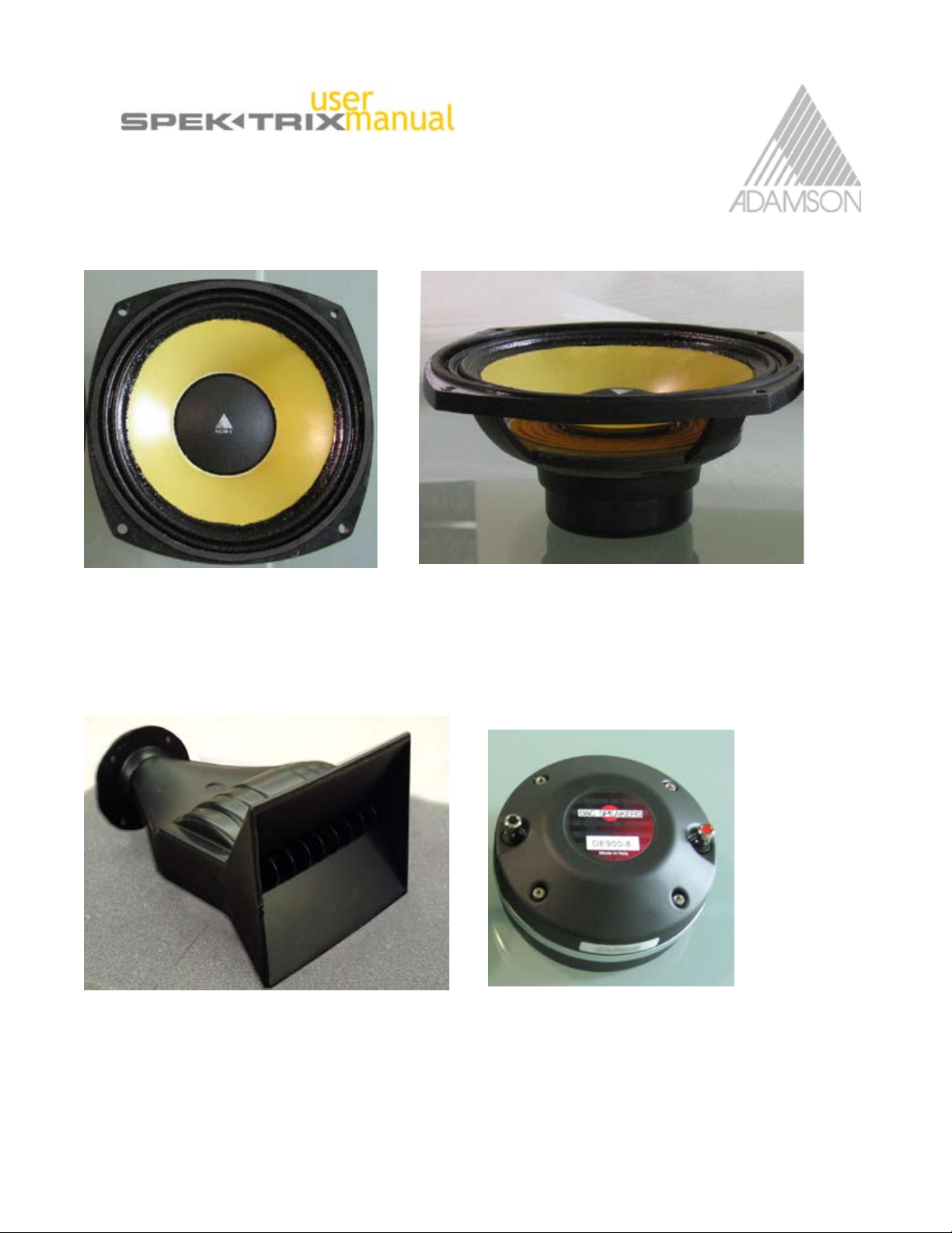
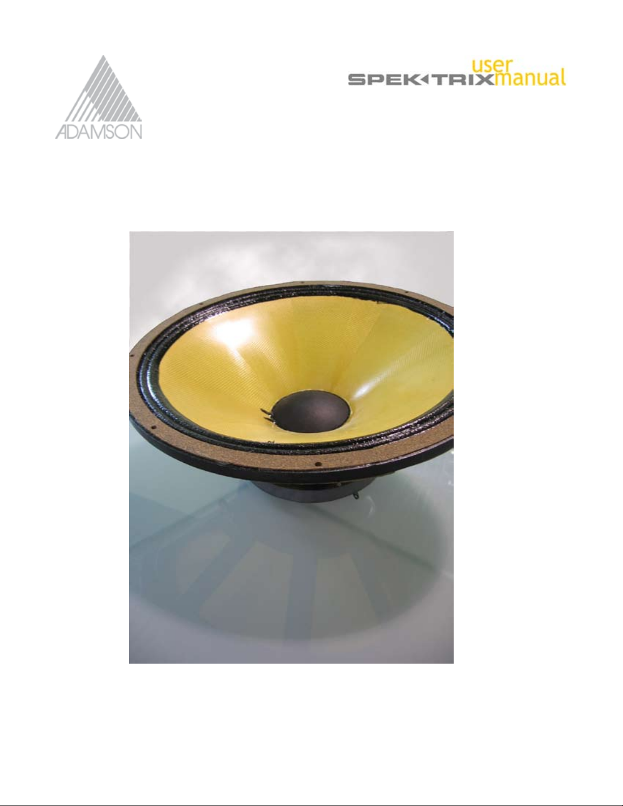
1.3 What’s Inside the SpekTrix?
The Adamson ND8-L
Product Code:
861021
The Adamson SpekTrix HF Sound Chamber
The Adamson ND8-M
Product Code:
861020
SpekTrix HF Driver B&C DE900
Product Code:
743110 SpekTrix, 743120 SpekTrix W
Product Code:
860057
SpekTrix Series User Manual 7 of 72
Page 8
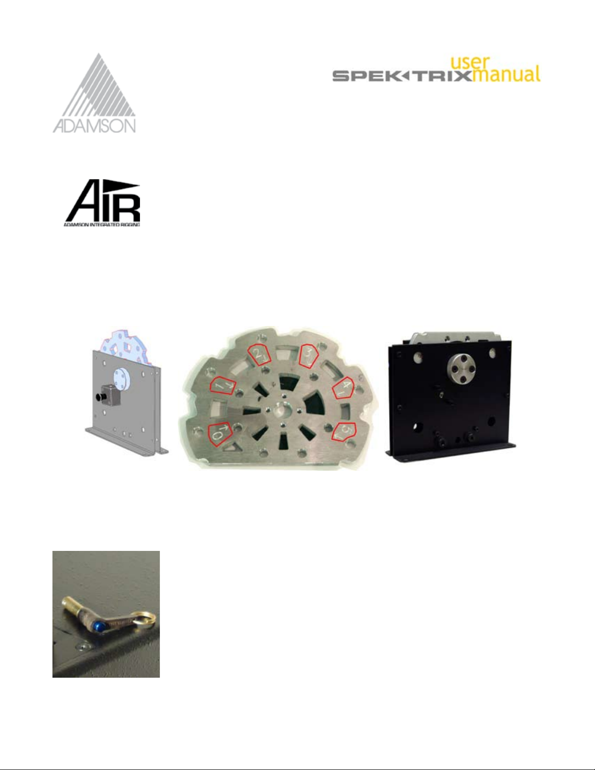
1.4 Rigging Hardware
The SpekTrix Series features AIR™ system revolving disk flying hardware that is recessed, attached and hidden
inside the box when arrayed. Precise angular positioning of the SpekTrix is controlled by the rotating wheel,
selecting the rigging angle on the revolving disk changes rear enclosure spacing, while the trapezoidal shape of
the enclosure ensures that there are no gaps in the front of the array.
The AIR™ Revolving Disk clearly indicated 6 precise rigging angles on a Logarithmic scale.
Product Code: 884145 SpekTrix Rigging Wheel
884147 SpekTrix W Rigging Wheel
The SpekTrix Push Pin
The Push Pin is used to secure the rigging frame to the SpekTrix boxes (one each side)
a s well as connecting subwoofer enclosures. Stacking plates are atttached to rigging
frame using push pins.
The SpekTrix Line only uses one size push pins.
Product Code:
881122
SpekTrix Series User Manual 8 of 72
Page 9
1.4 Rigging Hardware
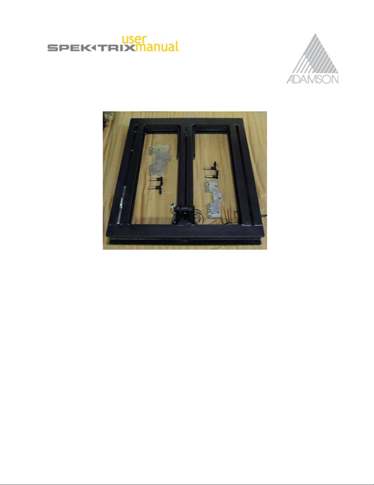
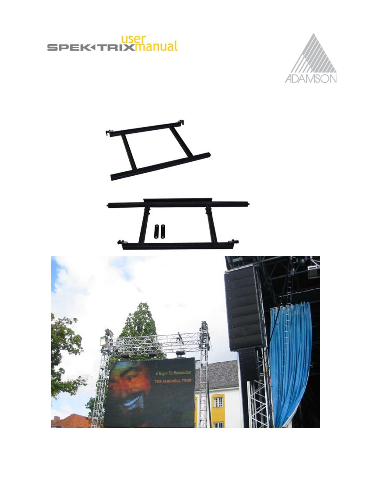
SpekTrix Rigging Frame
Product Code:
Aluminum: 920042
Steel: 920056
Rigging Frame Assembly:
One Lightweight Aluminium or Steel Frame
Push Pins x 4
SpekTrix Stacking Plates for SpekTrix x 2
and Optional Extended Stacking Plates for SpekTrix W x 2
The SpekTrix Lifting Frame forms the basis for the SpekTrix array and is capable of holding up to 16 SpekTrix
enclosures. The SpekTrix rigging frame is equipped with a single threaded moving pick point, enabling the center
of balance and tilt angle to be precisely adjusted.
Additional lifting frame components can be removed from the frame to allow for easy packing and transport.
Two lifting frames may be transported with right (top) sides facing, so that the threaded pick point rests within the
channel of the other frame to create a flat pack. Adamson Also offers a compact SpekTrix rigging flightcase,
which neatly holds 2 Frames and has 2 drawers for additional accessories such as motor etc.
IMPORTANT: Carefully inspect the lifting frame and brackets prior to every use to ensure there are no cracks,
corrosion or deformity that could compromise the safety of an array. Using a damaged frame could result in
mishap or serious injury.
SpekTrix Series User Manual 9 of 72
Page 10
1.4 Rigging Hardware
Stacking Plates and Extended Stacking Plates
Product Code:
880146 SpekTrix Stacking Plates
883038 SpekTrix W Extended Stacking Plates
Ground Stacking Plates are used for ground stacking the SpekTrix cabinet, one attached to each side of the
rigging frame. The Ground Stack Adapter Plates facilitate both positive and negative angle ground stacking. The
plates feature a series of holes which are marked with the corresponding angle. These are only used in ground
stacking applications.
SpekTrix Series User Manual 10 of 72
Page 11
1.4 Rigging Hardware
Underhang Kits
Y10 / SpekTrix
Product Code: 920204
Y18 / SpekTrix
Product Code: 920203
Please refer to the “Y-Axis User
Manual” for instructions on the use of
Adamson Underhang Kits.
Y18 Flown with SpekTrix using Adamson Underhang kit.
SpekTrix Series User Manual 11 of 72
Page 12
1.5 Accesories
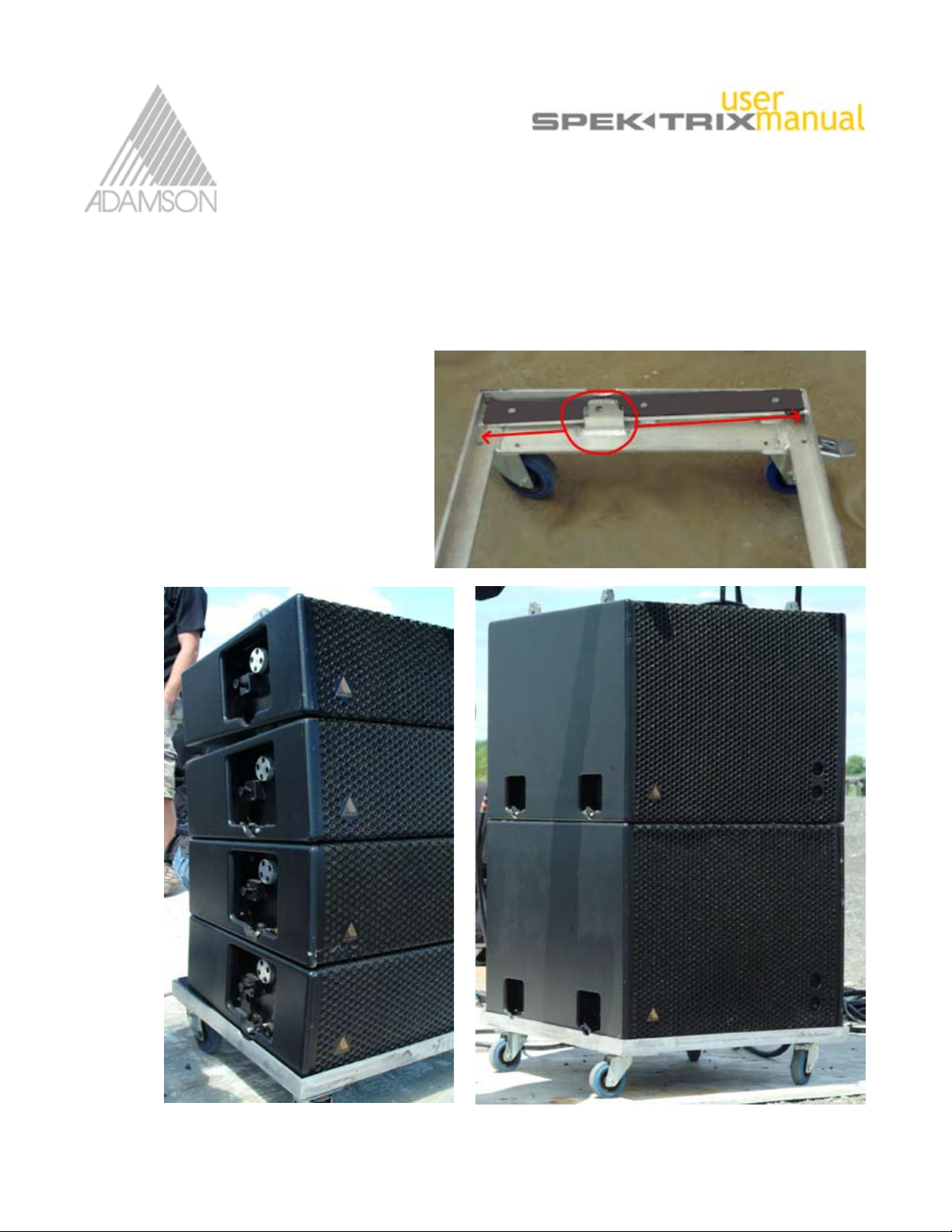
Dolly Boards
1. SpekTrix 4-stack/ 3 SpekTrix with 1SpekTrix W
2 SpekTix Subs x 2
Product Code:
970178 SpekTrix & SpekTrix W Dolly
970179 SpekTrix Sub Dollly
The dolly for a SpekTrix - 4 stack is configured
so that the captive rigging point and angle,
support the enclosure.
Dollies are included in every SpekTrix
purchase.
SpekTrix Series User Manual 12 of 72
Page 13
1.5 Accesories
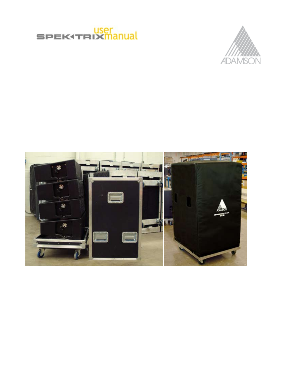
Flight Case
Product Code: 890148
Description:
Flightcases are configured the same way as Dolly Boards.
3 SpekTrix or 3 SpekTrix with one SpekTrix W enclosure per case. There are no flightcases available SpekTrx Subs.
Soft Covers for SpekTrix Sub
Product Code: 891043
Description:
SpekTrix Sub soft covers are custom made with padded waterproof Cordura. They are designed to be used with
a 2 SpekTrix Sub stack. The top includes a pocket designed to take a plywood square, which can be added in
order to truckpack additional cabinets on top of the SpekTrix Subs when needed. This will protect the SpekTrix
Sub’s spring loaded AIR Rigging hardware when in transit. All SpekTrix Sub covers are screen printed with the
Adamson Logo and product name.
SpekTrix Series User Manual 13 of 72
Page 14
1.
1.5 Accesories
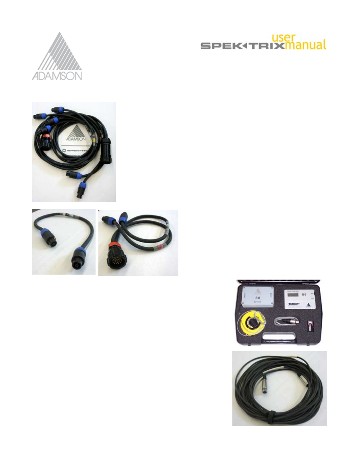
Cabling PART #’s
NL8-3’ #940054
male-male (picture 2)
NL8-10’ #940055
male-male
NL8-25’ #940056
male-male
NL8-50’ #940057
male-male
NL8-100’ #940058
male-male
Soca 50’ #900531
19 pin 12 AWG
Soca 100’ #900530
19 pin 13 AWG
Soca150’ #900529
19 pin 13 AWG
Soca Splay #900532
19 pin soca to 2 x NL8 (picture 1 & 3)
Soca Splay Sub #900533
19 pin soca to 4 x NL8 (picture 1)
2.
Adamson Inclinometer Set
#940001
The measuring kit includes a digital inclinometer set and a tape measure
safely secured in a die-cut foam/durable plastic casing. The sensor is fitted
to the rigging frame or placed onto a cabinet which allows the measuring
of the aiming angle.
The sensor is connected to the display with a standard XLR3 cable
(picture 4) for remote access. When switching the inclinometer on, the laser
beam is automatically activated, facilitating not only the visual control of
the array’s vertical aim but the horizontal positioning as well.
The tape measure included in the kit is used to measure the trim height of
the array, in order to
match it with your Shooter® simulation.
Two separate batteries enable the use of the inclinometer, even if the laser
battery is low.
The sensor is fastened to the rigging frame with a steel safety rope.
SpekTrix Series User Manual 14 of 72
3.
4.
Page 15

product specications
- FULL RANGE 3-WAY CABINET
- TRUE LINE SOURCE ARRAY
- ADAMSON WAVE SHAPING SOUND
CHAMBER
- AIR™ SYSTEM REVOLVING DISK RIGGING
- COMPACT & LIGHTWEIGHT
The compact SpekTrix offers all the benefits of a True line
Source via patented wave shaping sound chamber
technology (US Patent # 6,581,719) The SpekTrix wave
shaping sound chamber produces a slightly curved
wave front in the HF that is comparable to the wavefront
found in the Y-Axis. The 5 degree Vertical coverage, 3 Way
SpekTrix Enclosure exhibits extremely high output for it’s
compact size.
Designed for optimal ease-of-use, smaller sound companies will also appreciate the cabinet’s affordability, light
weight and compact size. The AIR™ (Adamson Integrated Rigging) system revolving disk flying hardware makes
setting up an entire array so easy, it can be accomplished by one person. There’s no extra rigging hardware to
misplace - everything is attached and recessed inside the enclosure.
When arrayed, AIR™ flying hardware is concealed, giving the system a modest, sleek look that makes it well
suited for installation in small to medium-sized venues, theaters and houses of worship.
Product Code 900042
Page 16
technical specications
FEATURES
The Adamson SpekTrix is a three-way cabinet that
exhibits extremely high output for a compact box. The
enclosure incorporates two unique Adamson 8.5” Kevlar,
neodymium drivers - one ND8-L mid-bass driver and
one ND8-M mid-range driver, and one B&C DE 900
compression driver mounted on a patented Adamson
wave shaping sound chamber.
The sound chamber has a defined coverage pattern of
5-degrees V by 120-degrees H, and is similar to the inner
body of a Y-Axis drive module, giving the SpekTrix a slightly
curved, iso-phase wave front comparable to that of the
Y-Axis system.
The SpekTrix features AIR™ system revolving disk flying
hardware that is recessed, attached and hidden inside
the box when arrayed, making the cabinets perfect for
industrial applications where you want a system to look
discreet. A single person can easily set up an entire
array.
The SpekTrix rigging frame is equipped with a single
threaded moving pick point, so the center of balance
and tilt angle can be precisely adjusted with little effort.
The sleek, trapezoidal SpekTrix cabinet weighs only 62 lbs,
and is constructed from rugged 5/8” Baltic birch with a
dual component black speckle coat finish. All SpekTrix
cabinets are supplied with lightweight, rugged aluminum
dolly boards (four cabinets per dolly), with flight cases
available upon request.
Specifications are subject to change without notice.
PHYSICAL DATA
Dimensions & Weight
Height (cm) 8.6” (22)
Width (cm) 27.9” (71)
Depth (cm) 18.91” (48)
Weight (Kg) 62lb (29.03)
Shape 5 degree trapezoid
Box Finish
Hardware Finish
Optional Accessories Aluminum Rigging Frame
Rigging AIR™ Revolving Disk Rigging
Protective grille 16 Gauge cold steel
Cabinet Construction Rugged 11 ply Baltic Birch
Waterborne Acrylic
Water Based Bake Enamel
with 6 precise rigging angles
on a logarithmic scale
TECHNICAL DATA
Frequency Response (+/-3dB)
Full Range Preset 80 Hz to 18 KHz
With Sub 35 Hz To 18 kHz
Frequency Range
with Xover Preset 110 Hz – 18 kHz
Maximum SPL
(Continuous / Peak)
with Xover Preset 130.1dB / 136.1dB
with Full Range Preset 129.8dB / 135.8dB
Directivity
Horizontal 120 degrees
Vertical (per element) 5 degrees
Sensitivity (2.83V @ 1m)
LF 94.5dB / 80 Hz – 250 Hz
MF 99dB / 250 Hz – 900 Hz
HF 112dB / 900 Hz – 18 kHz
LF Section (Impedance
ohms)
MF Section (Impedance
ohms)
HF Section (Impedance
ohms)
Power Handling
(AES Program / Peak) LF
MF 250 / 500 / 1000
HF 80 / 160 / 320
Connection Neutrik Speakon™ NL8
ND8-L 8.5” Kevlar
neodymium Mid-Bass
driver (8ohms)
ND8-M 8.5” Kevlar
neodymium Mid-Range
driver (8ohms)
B&C DE 900 1.5”
compres. driver (8 ohms)
250 /500 / 1000
Page 17
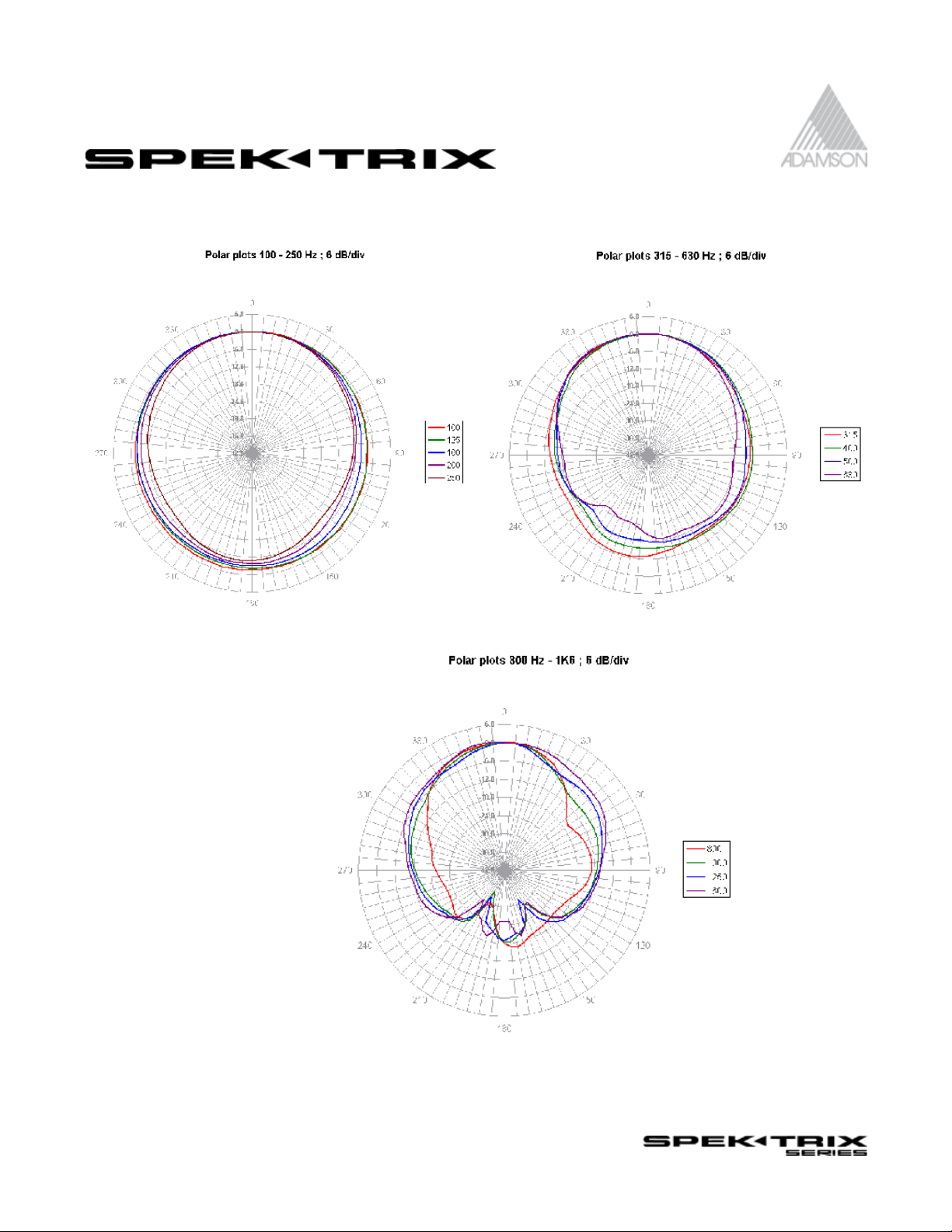
directivity diagrams
Page 18
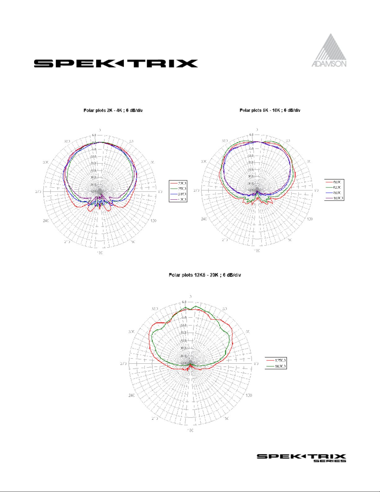
directivity diagrams
Page 19

directivity diagrams
Single enclosure measurement.
Low frequency directivity increases as more enclosures are added (as the length of the
array increases).
Page 20
product specications
- FULL 3-WAY CABINET
- TRUE LINE-SOURCE
- AIR™ SYSTEM PRECISION FLYING
HARDWARE
- ADAMSON WAVE SHAPING SOUND
CHAMBER
COMPACT & LIGHTWEIGHT
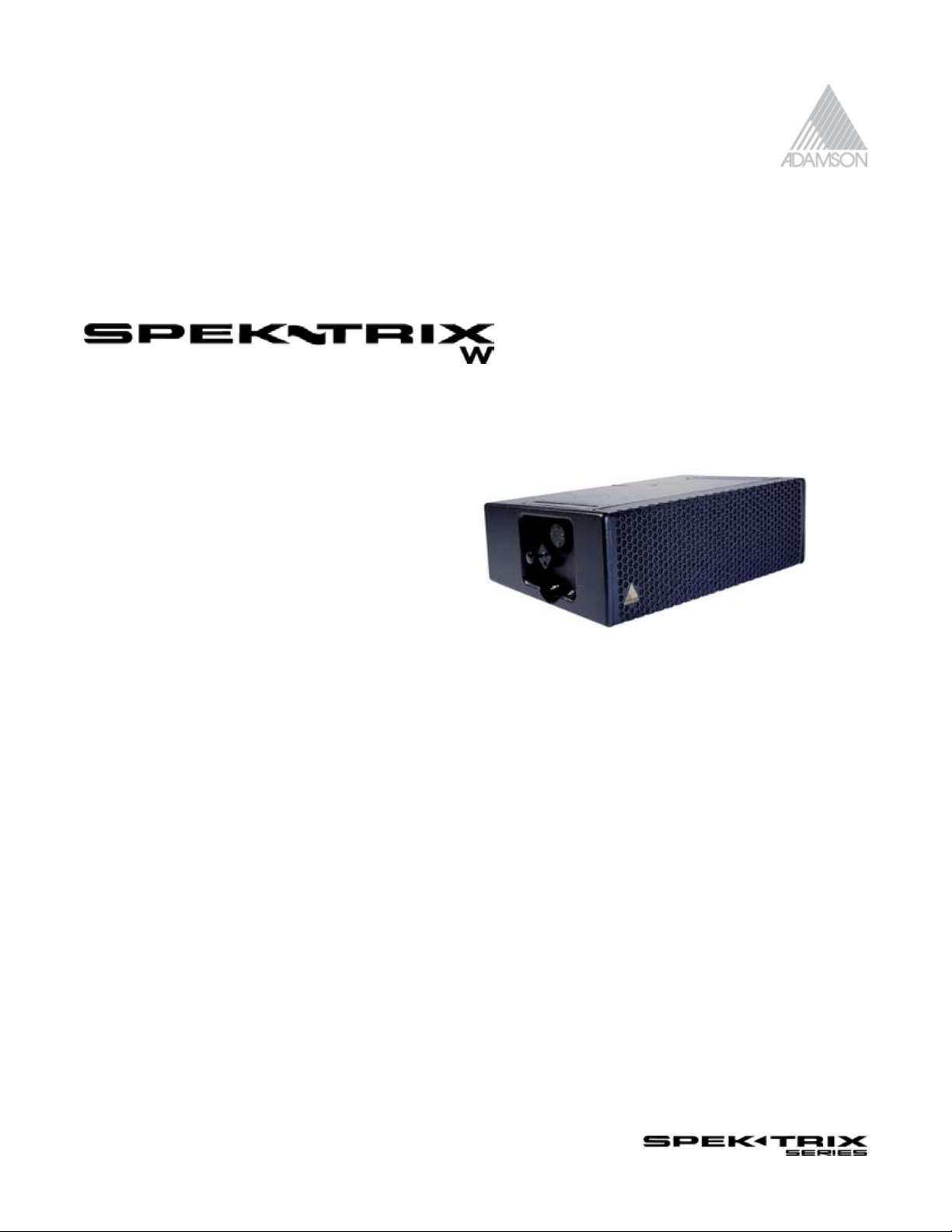
The SpekTrix W brings a new element of versatility to the
SpekTrix compact line array series, while offering all the
benefits of line-source technology via its patented Adamson
wave shaping sound chamber.
The 15-degree trapezoidal cabinet design makes it easy to
achieve extreme downward angles at the bottom of an array
- ensuring optimal coverage in the front rows - and is perfect
for use in wide vertical coverage array designs (for instance, in
theaters with multiple balconies).
The compact SpekTrix W offers all the benefits of a True line Source via patented wave shaping sound chamber
technology (US Patent # 6,581,719) The SpekTrix wave shaping sound chamber produces a slightly curved wave
front in the HF, that is comparable to the wavefront found in the Y-Axis.
The SpekTrix W incorporates the revolutionary AIR™ (Adamson Integrated Rigging) system and offers three precise
rigging angles on a revolving disk. Suitable for touring applications, various fill requirements and installation in
small- to medium-sized clubs, theatres and houses of worship, the SpekTrix W raises the bar and delivers the full
features and flexibility you need in a compact system.
Product Code 900041
Page 21
technical specications
FEATURES
The Adamson SpekTrix W is a three-way cabinet that exhibits
extremely high output for a compact box.
The 15-degree trapezoidal enclosure incorporates two
unique Adamson 8.5” Kevlar, neodymium drivers - one
ND8-L mid-bass driver and one ND8-M mid-range driver,
and one B&C DE 900 compression driver mounted on a
patented Adamson wave shaping sound chamber.
The sound chamber produces a slightly curved, iso-phase
wave front, and has a defined coverage pattern of 15degrees Vertical by 120-degrees Horizontal.
The sleek, trapezoidal SpekTrix cabinet weighs only 64 lbs,
and is constructed from rugged 5/8” Baltic birch with a
waterborne acrylic finish.
PHYSICAL DATA
Dimensions & Weight
Height (cm) 10.4” (26.4)
Width (cm) 27.9” (71)
Depth (cm) 18.91” (48)
Weight (Kg) 64lb (29.03)
Shape 15 degree trapezoid
Box Finish
Hardware Finish
Optional Accessories Aluminum Rigging Frame
Rigging AIR™ Revolving Disk Rigging
Protective grille 16 Gauge cold steel
Cabinet Construction Rugged 11 ply Baltic Birch
Waterborne Acrylic
Water Based Bake Enamel
with 3 precise rigging
angles
TECHNICAL DATA
Frequency Response (+/-3dB)
Full Range Preset 80 Hz to 18 KHz
With Sub 35 Hz To 18 kHz
Frequency Range
with Xover Preset 110 Hz – 18 kHz
Maximum SPL
(Continuous / Peak)
with Xover Preset 130.1dB / 136.1dB
with Full Range Preset 129.8dB / 135.8dB
Directivity
Horizontal 120 degrees
Vertical (per element) 15 degrees
Sensitivity (2.83V @ 1m)
LF 94.5dB / 80 Hz – 250 Hz
MF 99dB / 250 Hz – 900 Hz
HF 112dB / 900 Hz – 18 kHz
LF Section (Impedance
ohms)
MF Section (Impedance
ohms)
HF Section (Impedance
ohms)
ND8-L 8.5” Kevlar
neodymium Mid-Bass
driver (8ohms)
ND8-M 8.5” Kevlar
neodymium Mid-Range
driver (8ohms)
B&C DE 900 1.5” compr.
driver (8 ohms)
Specifications are subject to change without notice.
Power Handling
(AES Program / Peak) LF 250 / 500 / 1000
MF 205 / 500 / 1000
HF 80 / 160 / 320
Connection Neutrik Speakon™ NL8
Page 22
product specications
- HIGH SOUND PRESSURE LEVELS
- CONVENTIONAL or TRUE CARDIOID
PERFORMANCE
- ENCLOSURE DESIGNED FOR MAXIMUM
EFFICIENCY
- FREQUENCY RESPONSE OF 40 - 160Hz
- AIR™ SYSTEM FLYING HARDWARE
Designed as a companion to our SpekTrix compact
line array cabinet, the SpekTrix Sub was the first
Adamson enclosure to introduce Convertible Cardioid
Technology, and is a single-sided box that can be
arrayed conventionally (all facing the same way) or
can be arrayed in back-to-front pairs for true cardioid
performance.
The SpekTrix Sub is equipped with two powerful AW18 Kevlar bass drivers mounted in a tuned, vented and fully braced
cabinet. The precision-machined, spring-loaded rigging hardware recesses into the cabinet when not in use and works
in conjunction with other AIR™ system rigging elements to allow for a variety of configurations - attach the subs to the
rigging frame and hang the SpekTrix underneath them, or stack your subs directly on the floor and ground stack your
array on top.
The SpekTrix Sub loads in pairs on an aluminum dolly board and has been designed to ensure an easy truck pack.
Product Code 900043
Page 23

technical specications
FEATURES
A compact, sub-bass loudspeaker designed to provide
high SPL extended bass to Adamson SpekTrix enclosures,
the SpekTrix Sub is equipped with two powerful AW18
18” Kevlar low frequency drivers in a tuned, vented
enclosure.
The cabinet is fully braced to minimize LF resonance and
maximize efficiency. Four sets of captured, precisionmachined aluminum rigging hardware are spring-loaded
and retract into the cabinet body when not in use; and
four NL8 connectors (two front, two back) enable easy
cable loop-thru regardless of the sub’s orientation.
- Dual AW18 18” Kevlar Bass drivers
- Frequency Response of 40 - 160 Hz
- Efficient Cabinet Design
- Durable, Waterborne Acrylic Finish
- Captured, Spring-Loaded Precision Rigging Hardware
- Easy Truck Pack with 2 cabinets per dolly paired with
optional waterproof softcovers for protection
PHYSICAL DATA
Dimensions & Weight
Height (cm) 23” (58.5)
Width (cm) 28” (64)
Depth (cm) 32” (84)
Weight (Kg) 170lb (77)
Shape Rectangular
Box Finish
Hardware Finish
Flying Points
Protective grille 14 Gauge cold steel
Cabinet Construction
Accessories Aluminum Dolly Board
Optional Accessories
Waterborne Acrylic
Back Bake Enamel
Captured spring-loaded
precision machined
aluminum
Rugged 15-ply Baltic
Birch, internally braced
Aluminum or Steel
Rigging Frame,
Waterproof Soft cover
TECHNICAL DATA
Frequency Response
(+/-3dB)
Full Range Preset 40Hz - 160Hz
Frequency Range
Xover Preset 35 Hz – 110 Hz
Maximum SPL
(Continuous)
Directivity Convertible to Cardioid
LF Section
Power Handling
(AES / Program / Peak) LF 600 / 1200 / 2400
Nominal Impedance 4 ohms
Sensitivity (2.83V @ 1m) 105.8dB
Connection
132dB
Two Adamson AW18 18”
Kevlar Low Frequency
Drivers
Neutrik Speakon™ NL8
(2 front, 2 rear)
Specifications are subject to change without notice.
Page 24

2.0 Designing a Project
SpekTrix Series User Manual 24 of 72
Page 25

2.1 Shooter Software
Adamson Shooter Software is available by request only. It’s free for all Y-Axis, SpekTrix and Metrix partners,
designers and end-users. Please call Adamson Systems Engineering 905-982-0520 to request the FTP download
information, or website link password for the most current version available.
http://www.adamsonproaudio.com/technical_support/get_adamson_shooter
SpekTrix Series User Manual 25 of 72
Page 26

Quick Start guide
Introduction
The purpose of this guide is to help new users in their first setup with the Adamson Shooter®
predictive software for Adamson Y-Axis and SpekTrix speaker systems. Further detail can be
obtained from the Adamson Shooter® User Manual and is recommended for all users. All
users should also attend Adamson Certification Training.
Disclaimer
The Adamson Shooter® Software, Shooter® Quick Start Guide and Shooter® User Manual are
not meant to instruct the user in safe and standardized rigging methods.
Requirements
1. Microsoft Windows™ compatible computer version ’98 or better
2. Internet connection or Shooter® Software CD
3. Measuring device or venue CAD drawings
4. Knowledge of Adamson Y-Axis and/or SpekTrix rigging systems
5. Working knowledge of coordinate geometry
Software Installation
1. Insert Shooter® CD or download Shooter® installation file. Shooter® may be
downloaded at http://www.adamsonproaudio.com/shooter password: retoohS
2. Download file: ”YAXISShooter 2.5.5.zip” or higher
3. Unzip the file and Click “Setup.exe” This will launch the installer. Follow the on screen
instruc tions.
Start A New Project
1. Launch the “YAXIS Shooter v 2_5_5” Program
2. Under “File” Choose “Open”
3. Choose “BLANK.yas” and Click “Open”
4. Choose metric or standard measurement system in the top right corner by clicking ft/lb
or m/Kg.
5. Click “Vertical View” to view the blank document.
SpekTrix Series User Manual 26 of 72
Page 27

Quick Start guide
Defining The Space
In this graph, column “1” is the floor at the beginning point of section 1(red), 2 (pink), 3(green), or 4 (blue), and
column “2” is the end point. A section can be an area of audience where the vertical pitch (incline) changes or
a balcony is present. Like all CAD software (X) is used for the Horizontal plane and (Z) for the Vertical plane. (X) is
always measured from the front of the stage and (Z) from the floor/ground level.
1. In section 1 column 1x, place the distance between the front of the stage and the first row of audience.
2. In section 1 column 1z, place the height of the floor. (Usually “0” for the first level)
3. In section 1 column 2x, place the distance between the front of the stage and the last row of audience
in this section
4. In section 1 column 2z, place the height of the floor at the last row of audience in this section.
5. To add another standing/seating area (section 2) which is continuous with section 1, press “LINK”
(automatically places the end distance of a section for the beginning distance of a new section hence
connecting the two), or add it manually to 1x of the pink row.
6. If section 2 has an elevation starting immediately at the front row, such as a balcony, do NOT link these
sections, but place the distance value manually and add height value to pink 1z.
7. In section 2 for column 2x, place the distance between the front of the stage and the last row of the
second section. For an elevation add the height of the floor at the last row of section 2 to 2z.
Continue to include all audience sections. One can switch between “Stand” or “Seats” (to adjust the average
ear height).
8. Adjust “Stage Height” and “Offset” if desired.
SpekTrix Series User Manual 27 of 72
Page 28

Quick Start guide
Speaker Selection
The software can determine the ideal quantity of boxes and the location of the rigging frame, for a given
space, however practical limitations will need to be determined by the user. The software will make it readily
apparent if you do not have enough boxes to cover the audience evenly, especially in the case of vertical
coverage.
1. Based on the number and model of boxes in stock,
enter the quantity you are likely to use per side in the
application.
2. Enter the model of boxes you plan to use in the drop down
menus. (E.g. Y-10K = Y10’s with Kevlar drivers, S8-W = SpekTrix
Wave)
Locating The Rigging Frame
A balance must be found between what is best for sound quality and what is practical for the venue
application.
1. Choose either “Flown” or “Stacked”
2. Assess which factors are predetermined by the venue and enter them. For example, the array
might need to stay at a certain height for audience line of sight, or the array might need to be a
set distance from the front of the stage because of the venue’s rigging points.
3. 1X determines distance from stage, 1Z Height of the array.
It is often useful to hit “AUTO SHOOT” at this point, to get a starting height and frame angle.
SpekTrix Series User Manual 28 of 72
Page 29

Quick Start guide
1. Choose “Z Frame” to allow Shooter to choose the optimal height for the
rigging frame.
2. Choose “Frame Angle” to allow Shooter to choose the optimal Angle for
the rigging frame.
3. Choose “Near Field Limit” to start Shooters calculations at a defined
distance from the front of the Audience. Many applications require the use
of low power front or down fills.
4. Choose Boxes+Angles if you want Shooter to determine the optimal
amount of boxes for the application. Otherwise choose “Only Angles”.
5. Press Go.
Adjust Frame And Box Angles
Keep in mind that what you are trying to achieve is a practical balance between, speaker placement, vertical
coverage, equal SPL between front and rear audience members, and number of boxes to be used.
1. Hit S.P.L (F3) to see results. To adjust desired SPL level, scale “Distribution Factor” up or down.
2. Vary the angle and height of the rigging Frame and the Angles between boxes to achieve even SPL
coverage.
SpekTrix Series User Manual 29 of 72
Page 30

Quick Start guide
Horizontal View
It’s useful flip back and forth, between “Vertical” and “Horizontal View”
-While working, make
sure you’re in Map
Mode (F5), when
checking design switch
to S.P.L. Mode (F7)
to get a feel for the
coverage.
(S.P.L. Mode (F7) recalculates coverage
after every change,
thus slowing down the
design process)
-One can also adjust
the P.A. system Width
and Angle, as well as
the Stage Width and
Shape in the “Horizontal
View”. To work on a
single rig, (E.g. a “centre
cluster”)
turn off “stereo”.
1. For drafting more complex areas select
1X in row 1. a “+“cursor will appear at
the front of the stage.
2. “Click” on the “+”and stretch to
determine the shape of the first row of
the audience. “Click” to release when
cursor is in the desired place.
3. Select 2X to determine the shape of
the last row of floor level 1.
Remember you can also enter values
manually. Continue to row 2, 3, 4, if
floor level 1 requires more complex
shapes. To switch to floor level 2, 3 or 4,
use the drop menu on top of the page.
SpekTrix Series User Manual 30 of 72
Page 31

Quick Start guide
4. Click on “Grid” and adjust grid size. For a more detailed S.P.L. calculation, choose a tighter (smaller) grid
size and vise versa, then click S.P.L. (F7) to see the coverage.
Summaries can be obtained by clicking “Mechanical View” for illustrations of the array and rigging frame,
“Rigging Plot” for key rigging measurements. Both can be printed out as a “screen shot” and distributed to the
rigging crew as a handy reference sheet.
(Press “print Scrn” on your keyboard, “Open” a new project in ‘Microsoft Paint’, ‘Adobe Photoshop’, or any
other picture manipulation program and paste it for resizing and cropping. You can also paste it into a ‘Word’
document and print as is.)
For a “Shooter user sheet” with no illustrations go to the “File” menu and click “Print User Sheet”.
Keep in mind that Shooter has many more detailed features, which are outlined in The Adamson Shooter User
Manual.
SpekTrix Series User Manual 31 of 72
Page 32

3.0 Total System Approach
Adamson Systems Engineering has long been using
Lab.gruppen amplifiers and XTA processors to power
and process SpekTrix Systems. All of our processor
settings such as gain structure, equalization, time and
phase alignment have been derived from extensive
testing using this specific equipment combination. The
use of this equipment evolved into a complete system
solution, adapted by Adamson partners around the
world.
Recently Adamson has added LAKE processing as a
supported solution, with a complete settings library
available by request and on-line.
We recognize the benefits of completely scaleable
system that can also use multiple elements from
Amplifier/Speaker load balancing.
To create a balanced amplifier load format common
to all SpekTrix systems, Adamson Systems Engineering
designed a specific driver compliment.
Each SpekTrix:
1) One 8 Ohm low frequency driver on pin 2 +/-
2) One 8 Ohm midrange driver on pin 3+/-
3) One 8 Ohm high frequency driver on pin 4+/-
Setting up processors and amplifiers
Processor settings, available for download on our website, are set in conjunction with the appropriate settings
on the amplifier, normally set at 29dB or 32 dB of gain. Please assure that these settings are correct and
correspond with the processor settings when configuring your set-up.
NOTE: Use only factory recommended equipment and settings. If you are using
amplifiers and/or processing other than our example, please consult the manufacturers
specification and instruction manual to assure that gain structures, limiting, equalization
and connections are set up in accordance to our speaker specification. Failure to do so
will result in inaccurate performance and risk of irreversible and /or personal damage,
and thereby voiding warranty.
For Lab.gruppen, to link inputs and set the amplifier gain, the manufacturer provided an 8-switch dipswitch
on the back of the amps. The center switches should be in the “up” position. and the gain should be set to
the appropriate combination on switch 1,2,3 for channel B, and 6,7,and 8 for channel A. The example is set
at 29dB. Link parallels input A to input B. To unlink amplifier channels A and B, move the two center switches,
4 and 5, to the down position. This will allow the user to have separate inputs to channel A and B of the
amplifier.
SpekTrix Series User Manual 32 of 72
Page 33

3.1 Turnkey Solutions
Adamson Turnkey Solutions can be ordered complete with Power Distribution panels and A.I.D. Panels.
There are 110v or 220v units available for Power Distros, and both A.I.D. Touring and Install versions are available
with both Socapex and NL8 cabling solutions.
Part #’s:
Install w. Socapex # 900538
Install w. NL8 # 900511
Part #’s:
Touring w. Socapex # 900520
Touring w. NL8 # 900510
Adamson’s Audio Integrated Distribution (A.I.D) panels were designed in consultation with FOH and system
engineers to create a common standard of audio connectivity and distribution for all Adamson Y-Axis partners.
It provides a recognizable, high quality interface standard for cross rental, co-production and dry-hire. Industry
standard socopex and NL cables allows for fast and easy connectivity to- and from amplifier racks, with a variety
of options for shared audio processing, bussing and distribution. The Panel minimizes clutter, extra equipment,
cables, manpower and space, saving premium dollars to the equipment provider, and ultimately the client.
Adamson Audio Integrated Distribution Panel is a 19” rack-mount unit, 2-U high and 10.25” deep. It provides front
panel access to processor and amplifier in- and outputs, and is completely dynamic in configuration by using
XLR and NL patch points on the back-face. For user manual go to www.adamsonproauido.com/technical_
support
Part #’s:
AC Distro 220 Version
#920207
AC Distro 110 Version
#900537
The Adamson A/C Panel is designed to power Lab.gruppen amplifiers. The input can be modifed for your unique
needs. The outputs consist of 3 x single receptacle Hubbel TL3 30A (nema L5-30R) and 2 x duplex receptacle
standard 20A. 1 duplex receptacle is located at the front for utilities.
The Adamson A/C Panel occupies a 2 unit rack space and is 19 inches wide.
SpekTrix Series User Manual 33 of 72
Page 34

3.2 Pin Configuration Table
For your convenience, below is a pinout chart used in most of our products.
Backpanel Frontpanel Frontpanel Splays Splays Splays
NL4 input NL8 panel SOCO 19pin 2NL8 4NL8 sub 4NL4
1A-1 1A 1-/+ 1 - Pin 1,2 BRN 1-/+ BRN 1-/+ BRN 1-/+
1A-2 1A 2-/+ 1- Pin 3,4 BRN 2-/+ BRN 2-/+ BRN 2-/+
1A-2 1A 3-/+ 1- Pin 7,8 BRN 3-/+ RED 1-/+ RED 1-/+
1A-4 1A 4 -/+ 1- Pin 9,10 BRN 4-/+ RED 2-/+ RED 2-/+
1B-1 1B 1-/+ 1- Pin 11,12 RED 1-/+ ORN 1-/+ ORN 1-/+
1B-2 1B 2-/+ 1- Pin 13,14 RED 2-/+ ORN 2-/+ ORN 2-/+
1B-3 1B 3-/+ 1- Pin 15,16 RED 3-/+ YEL 1-/+ YEL 1-/+
1B-4 1B 4-/+ 2- Pin 1,2 RED 4-/+ YEL 2-/+ YEL 2-/+
2A-1 2A 1-/+ 2- Pin 3,4
2A-2 2A 2-/+ 2- Pin 5,6
2A-3 2A 3-/+ 2- Pin 7,8
2A-4 2A 4-/+ 2- Pin 9,10
2B-1 2B 1-/+ 2- Pin 11,12
2B-2 2B 2-/+ 2- Pin 13,14
2B-3 2B 3-/+ 2- Pin 15,16
2B-4 2B 4-/+
Electronic colour code
Black 0
Brown 1
Red 2
Orange 3
Yellow 4
Green 5
Blue 6
Violet 7
Grey 8
White 9
This is the code used to identify values on, for instance, resistors or capacitors, or to identify cable
numbers in multiple cable runs. By using rings of colours in a specific pattern, one can represent
numerical “base 10” counting systems To represent numbers 1 thru 9, only one colour ring is used.
A second ring of colours allows 2 digit numbers, 0 to 99, a third ring 0 to 999 and so on. A black
ring represents all zero values or columns not used.
For example, the number 10 in a three-ring code is represented by black-brown-black. The
number 256 is represented by red-green-blue. A value of 1 in a three-ring colour code would be
represented by black-black-brown.
SpekTrix Series User Manual 34 of 72
Page 35

3.3 Amp and Pin Configurations
Product Specific Amplifier and Pin Configurations are available by request from Adamson Systems Engineering
+1 905 982 0520 And also available at our website’s Technical Section:
www.adamsonproaudio.com/technical_support/amp_configurations
www.adamsonproaudio.com/technical_support/pin_configurations
PDF Example of a Standard
Configuration for 4 SpekTrix with
2 SpekTrix Subs flown, using NL8
Connectors.
Note: all examples integrate Lab.
gruppen amplifiers and Adamson
AID Panels and Power Distribution
Panels.
For more details on these panels
please download user maniuals
found on our website
www.adamsonproaudio.com/
technical_support/user_manuals
SpekTrix Series User Manual 35 of 72
Page 36

3.4 Presets for Processors
Adamson Systems Engineering Specified Racks include XTA processing. The idea behind this is the facilitation of
cross rentals between companies, as well as producing the best possible sound with Adamson Speakers.
By popular demand LAKE and PLM setting are also available.
Please contact Adamson Systems Engineering 905-982-0520 or visit our technical support section on our
website: www.adamsonproaudio.com/technical_support
for up-to-date settings downloads.
SpekTrix Series User Manual 36 of 72
Page 37

4.0 Rigging and Cabling Instructions
4.1 Precautions
DO NOT put your hands between enclosures.
SOME AREAS MIGHT HAVE PINCH HAZARDS!
Make sure a certified rigger installs your rigging points and hoists. Confirm that the
rigging points are certified for the amount of weight you plan to hang. Refer to
Adamson Shooter’s Mechanical View for load and rigging details.
SpekTrix Series User Manual 37 of 72
Page 38

4.2 Flying the Array
IInstalling the SpekTrix System is simple, fast and safe.
A SpekTrix array can be installed in less than 10-15 minutes depending of the lenght of the array.
For a efficient and fast installation, (allthough the spekTrix system can be installed by a single person), a system
Technician, a stage hand and a rigger who in charge of the hoist remote, should be present.
The technician and stage hand are in charge of prepping the array prior to installation.
The array geometry and positioning is determined by the Shooter Software prior to installation.
it’s important to have the design on a computer screen or as a print out available, to easily determine frame
and cabinet angles among other details.
You can also refer to the “SpekTrix Configuration Examples” for further ideas on the diverse uses and set-ups
achieved with the SpekTrix Series.
Array positioning of zero through five degrees per enclosure can be set without the use of any
additional hardware Using the built-in AIR™system. Six precise rigging angles on logarithmic increments
are implemented by the insertion of stainless steel push pin into precision machined sliding bars that
extend from their home position to link the rear of the enclosures.
Between first SpekTrix Enclosure & rigging frame Always use position 2
SpekTrix Subs flown in Cardioid with an underhang of 8 SpekTrix
cabinets.
SpekTrix Series User Manual 38 of 72
6 SpekTrix flown
Page 39

4.2 Flying the Array
There are a few ways of flying the SpeTrix system; depending on the number of riggers, and whether you’re flying
SpekTrix Subs as well.
Example 1: Flying with Subs
1. Begin by attaching the rigging frame to the top sub. One can choose to keep the Frame Attached to the
Sub during transport.
2. attach your motor/s onto the rigging Frame
3. Release pins from the second sub
4. Turn the bottom Sub 180 degrees if
you’d like to fly it in a cardioid format. If
not, skip steps 3 & 4.
5. Connect top and bottom sub with an
NL8 cable and Attach another cable to
the bottom sub’s lower socket.
6. Release the dolly pins. (place the pins back into the cabinet as to not lose any pins.)
1. & 2.
5.4.
SpekTrix Series User Manual 39 of 72
3.
Page 40

4.2 Flying the Array
7. Set-up and Calibrate Inclinometer and reader to zero using a flat surface
8. Attach Inclinometer to the top of your rigging frame.
9. Adjust the frame angle to the proper position according the inclinometer reading.
10. Hoist subs up until the bottom box it at a working
level.
Note: When arraying alone (or if you simply prefer
this method of rigging) one must prepare the rigging
positions on the entire SpekTrix 4-stacks prior to flying
the system. When preparing enclosures, reference
your Shooter design, and make sure that when setting
the angles, you work your way from the bottom box to
the top box.
E.g. If there are 8 Spektrix enclosures in your design,
one dolly will have the settings from box 8 (at the
bottom) to box 5 (on top) and the next dolly from box
4 to box 1. To attain a spaceless connection between
the SpekTrix Sub above to the first SpekTrix enclosure,
the top SpekTrix box rigging wheel position must be
set to 4.
7.
8. & 9.
11. Wheel the SpekTrix stacks underneath the subs, lower the array of subs so that the rigging wheels on the top
SpekTrix box line-up and pin together with the provided push pins. Lift array to a comfortable working height and
wheel the second SpekTrix set underneath. Lower array so that you can pin the next four to the array using built in
AIR rigging wheel pin.
SpekTrix Series User Manual 40 of 72
10. & 11
3. (Next
Page)
Page 41

4.2 Flying the Array
When arraying with someone else, or without having had prep time between events and a venue requires a new
design, It might be faster to configure the array box by box. This method requires a minimum of 2 persons.
1. Place a person on both sides of the array with a possible third person operating the motor.
2. Follow the steps to hang the subs onto the frame. p. 40
3. Cabinet 1: Unhook the bottom push pin to release the enclosure from the stack, pull the rigging wheel’s safety
pin outward. Change the wheel position into the desired position (first enclosure should be set to 4 to attain a
gapless array) Push pin back into place.
4. Lift the enclosure, and place the push pin into place (on the previous cabinet, the rigging frame or in the
cabinet above) to hold the boxes together.
5. Release the following enclosure’s pins, turn the wheel to desired position push the pin back in.
6. Lift and pin to the previous enclosure.
4.
8. When working on a longer array, one might want to attach
5.
9.8.
cabling every 4 boxes, in order to reach the top enclosures.
6.
7. Continue this method until all
boxes are pinned together. If
needing more room to work, bring
the motor up to a desired level
every few enclosures.
7.
9. Wheel the next stack under the array and follow the previous
instructions.
FOR CABLING INSTRUCTIONS SEE NEXT PAGE
SpekTrix Series User Manual 41 of 72
Page 42

4.2 Flying the Array
1. When arraying SpekTrix directly to the
Rigging Frame to attain a gapless contact,
place the top enclosure’s rigging wheel to
position 2.
2. After setting-up and calibrating the
InclInometer, attach it to the rigging frame
and set your frame angle according to the
shooter file.
2.
1.
\
Cabling
1. Make sure that every box is plugged in according to factory suggested amp configurations. (See next 2 pages
for examples) You can also refer to our standard amp and pin configurations PDF’s available on our website. www.
adamsonproaudio.com/technical_support/amp_configurations/index.htm or call 905 982 0520 for custom set-
up and support.
All SpekTrix Series enclosures use NL8 connectors between boxes.
2. Loop all cabling at the back neatly together and hook to the rigging frame or tie it close to the array using a
strap and a hadle pocket, in order to keep them neat, to avoid getting cabling stuck or pulled off.
1.
SpekTrix Series User Manual 42 of 72
2.
Page 43

2 SpekTrix Subs with 8 SpekTrix - NL8
4.2 Flying the Array
2 SpekTrix Subs with 8 SpekTrix - Socapex
SpekTrix Series User Manual 43 of 72
Page 44

4.2 Flying the Array
1 SpekTrix Sub with 4 SpekTrix - NL8
4 SpekTrix Subs with 8 SpekTrix
- Socapex
SpekTrix Series User Manual 44 of 72
Page 45

4.2 Flying the Array
1.
2. & 3.
1. Lift slightly and confirm frame angle using inclinometer and laser. When using a 2 point hang with the SpekTrix,
you can adjust the frame angle using the motors once it is fully up in the air.
2. Loop the measuring tape to the bottom handle of the array, lift to the desired trim height and release the
measuring tape when ready. Remember to double up the lenght when using a “loop” method.
You can also use a piece of tape to attach it to the bottom enclosure, and pull the measuring tape out when
ready. (Note: This method might leave an awkward piece of tape hanging off the bottom box)
3. Check angle once in proper trim height to confirm planned coverage.
SpekTrix Series User Manual 45 of 72
Page 46

4.3 Ground stacking the Array
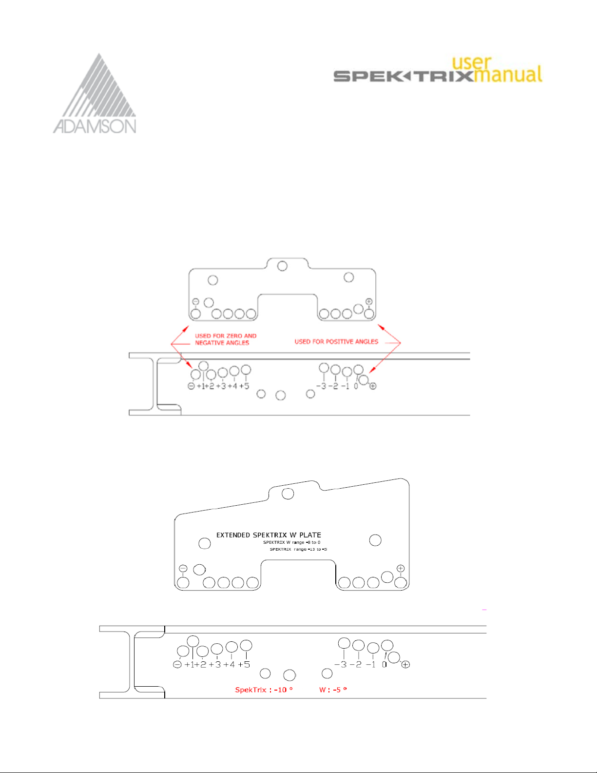
SPEKTRIX PLATE: Standard Stacking Plate for SpekTrix
The “Standard Stacking Plate” is used to achieve angles
of –3° to +5° between the first SpekTrix box and the
rigging frame in a stacking configuration.
1) Insert the plate into the frame
2) Place the “Ball Lock Pin” in either; the “+” slot for
positive angles, or in the “–” slot for or 0° or negative
angles.
3) Lock the plate with a second “Ball Lock Pin” in
the desired position.
SPEKTRIX W PLATE: Extended Stacking Plate for SpekTrix and W
The “Extended Stacking Plate” is used to achieve negative angles of -13° to -5° between the first SpekTrix
box and the rigging frame in a stacking configuration. It is also used to achieve negative angles of -8° to 0°
between the first SpekTrix W box and the rigging frame in a stacking configuration.
1) Insert the plate into the rigging frame
2) Insert the first “Ball Lock Pin” into either ”–” or “+“ slot depending on the desired
angle.
Remember that this plate’s ZERO position achieves –10° for SpekTrix boxes, and –5° for the W boxes .
Therefore:
Example 1: if the desired position for the first SpekTrix box is “–8”, the first pin would be inserted into the “+” slot
and second pin into the “+2” slot.
Example 2: If the desired position of the first WAVE box is “–7”, place first pin in the “ – ” slot and the second
pin in the “–2” slot.
Posion Indicated
on the Rigging
Frame
First SpekTrix W
Box Angle
(-5)
First SpekTrix
Box Angle
(-10)
SpekTrix Series User Manual 46 of 72
+5 0 -5
+4 -1 -6
+3 -2 -7
+2 -3 -8
+1 -4 -9
0 -5 -10
-1 -6 -11
-2 -7 -12
-3 -8 -13
Page 47

SpekTrix Series User Manual 47 of 72
Page 48

5.0 SpekTrix Configuration Examples
Stacking Configuration - Example 1
Configuration: 4 ground stacked SpekTrix on 2
SpekTrix Subs using the SpekTrix rigging frame.
Application: Coverage of a 40 meter/130feet deep,
level area with constant SPL front to back (6dB
change) and wide horizontal coverage.
SpekTrix Series User Manual 48 of 72
Page 49

5.0 SpekTrix Configuration Examples
Stacking Configuration - Example 1
SpekTrix Series User Manual 49 of 72
Page 50

5.0 SpekTrix Configuration Examples
Stacking Configuration - Example 2
Configuration: 4 ground stacked SpekTrix on 1
SpekTrix Sub using the SpekTrix rigging frame.
Application: Medium size arena with less low-end
demanding material.
SpekTrix Series User Manual 50 of 72
Page 51

5.0 SpekTrix Configuration Examples
Stacking Configuration - Example 2
SpekTrix Series User Manual 51 of 72
Page 52

5.0 SpekTrix Configuration Examples
Stacking Configuration - Example 3
Configuration: 3 ground stacked SpekTrix on 1
SpekTrix Sub using the SpekTrix frame.
Application: Front fills only - not to be used as a main
array
Note: The height of the array must be carefully adjusted with the Adamson
Shooter™ software to avoid excessive SPL in the front rows.
SpekTrix Series User Manual 52 of 72
Page 53

5.0 SpekTrix Configuration Examples
Stacking Configuration - Example 3
SpekTrix Series User Manual 53 of 72
Page 54

5.0 SpekTrix Configuration Examples
Stacking Configuration - Example 4
Configuration: 8 ground stacked SpekTrix using the
SpekTrix rigging frame plus 2 - 4 SpekTrix Subs.
Application: Medium to large scale arenas where
flying is not possible.
Note: The height of the array must be carefully adjusted with the Adamson
Shooter™ software to avoid excessive SPL in the front rows.
SpekTrix Series User Manual 54 of 72
Page 55

5.0 SpekTrix Configuration Examples
Stacking Configuration - Example 4
SpekTrix Series User Manual 55 of 72
Page 56

5.0 SpekTrix Configuration Examples
Flown Configuration - Example 5
Configuration: 6 flown Spek-Trix and 2 - 3 SpekTrix
Subs.
Application: Coverage for a level area, 35 to 45
meters deep with very high SPL.
Note: Optional small loudspeakers for front fills.
SpekTrix Series User Manual 56 of 72
Page 57

5.0 SpekTrix Configuration Examples
Flown Configuration - Example 5
SpekTrix Series User Manual 57 of 72
Page 58

5.0 SpekTrix Configuration Examples
Flown Configuration - Example 6
Configuration: 8 SpekTrix and 2 - 4 SpekTrix Subs.
Application: Coverage for a level area, 50 meters
deep with very high SPL.
Note: Optional small loudspeakers for front fills.
SpekTrix Series User Manual 58 of 72
Page 59

5.0 SpekTrix Configuration Examples
Flown Configuration - Example 6
SpekTrix Series User Manual 59 of 72
Page 60

5.0 SpekTrix Configuration Examples
Flown Configuration - Example 7
Configuration: 12 flown SpekTrix and 3 - 6 SpekTrix
Subs.
Application: Open air music festival. Coverage for a
level area, 60 to 80 meters deep with very high SPL.
Note: Optional small loudspeakers for front fills.
SpekTrix Series User Manual 60 of 72
Page 61

5.0 SpekTrix Configuration Examples
Flown Configuration - Example 7
SpekTrix Series User Manual 61 of 72
Page 62

5.0 SpekTrix Configuration Examples
Stacking Configuration - Example 8
Configuration: 2 SpekTrix Subs in “omni” mode.
Stacking Configuration - Example 9
SpekTrix Series User Manual 62 of 72
Configuration: 2 SpekTrix Subs in “cardioid” mode.
Note: The front and back cabinets are amplified separately and must be
processed with the Adamson DX6000 or XTA 4-Series Controllers.
Page 63

5.0 SpekTrix Configuration Examples
Stacking Configuration - Example 10
Configuration: 3 SpekTrix Subs in “omni” mode.
Stacking Configuration - Example 11
Configuration: 3 SpekTrix Subs in “cardioid” mode.
Note: The front and back cabinets are amplified separately and must
be processed with the Adamson DX6000 or XTA 4-Series Controllers.
Application: This configuration provides a 2:1 ratio
and gives maximum headroom.
SpekTrix Series User Manual 63 of 72
Page 64

5.0 SpekTrix Configuration Examples
Flown Configuration - Example 12
Configuration: 6 flown SpekTrix Subs in “omni” mode.
Flown Configuration - Example 13
SpekTrix Series User Manual 64 of 72
Configuration: 6 flown Spek-Trix Subs in “cardioid”
mode.
Note: The front and back cabinets are amplified separately and must be
processed with the Adamson DX6000 or XTA 4-Series controllers.
Application: This configuration provides a 2:1 ratio
and gives maximum headroom.
Page 65

5.0 SpekTrix Configuration Examples
Flown Configuration - Example 14
Configuration: 2 SpekTrix Subs flown with 10
SpekTrix.
Application: Theater with multiple balconies.
Flown Configuration - Example 15
Configuration: A SpekTrix Sub array flown beside a
large size SpekTrix array.
Application: This configuration is recommended
for optimal phase coupling between SpekTrix
Subs and SpekTrix.
SpekTrix Series User Manual 65 of 72
Page 66

5.0 SpekTrix Configuration Examples
Combination of Flown & Stacked
Configuration - Example 16
Configuration: the SpekTrix Sub can be also stacked
when flying possibilities are limited.
SpekTrix Series User Manual 66 of 72
Page 67

5.0 SpekTrix Configuration Examples
Flown Configuration - Example 17
Configuration: A SpekTrix array beside a SpekTrix
Sub array flown in “cardioid” configuration.
Front View
Back View
SpekTrix Series User Manual 67 of 72
Page 68

5.0 SpekTrix Configuration Examples
Flown Configuration - Example 18
Configuration: 2 SpekTrix W’s hung under 4 SpekTrix.
Application: Downfill.
SpekTrix Series User Manual 68 of 72
Page 69

5.0 SpekTrix Configuration Examples
Flown Configuration - Example 18
SpekTrix Series User Manual 69 of 72
Page 70

5.0 SpekTrix Configuration Examples
Flown Configuration - Example 19
Configuration: 4 flown SpekTrix W’s.
Application: Provides wide vertical coverage, ideal for
theaters with multiple balconies.
Note: 4 Boxes is an acceptable configuration only as a ground stack (see
examples 1& 2 & 3) or as a flown front fill shown here.
SpekTrix Series User Manual 70 of 72
Page 71

5.0 SpekTrix Configuration Examples
Flown Configuration - Example 19
SpekTrix Series User Manual 71 of 72
Page 72

 Loading...