

Page 1
Page 2
Declarations
Declarations
Directive 2006/95/EC: Low Voltage Directive
974-0001 E12
975-0001 E15
992-0007 E218
994-0001 E219
Directive 2006/42/EC: Machinery Directive
974-0001 E12
975-0001 E15
992-0007 E218
994-0001 E219
930-0004 E-Frame with Extender Beam
931-0009 E12/E15 - SpekTrix Underhang
938-0015 E12 Dolly
938-0004 E15 Dolly
938-0016 E218 Dolly
938-0020 E219 Dolly
938-0014 Dolly Stacking Legs
BUILT. STRONG.
E-Series | Declaration of Conformity
Page 2
Page 3
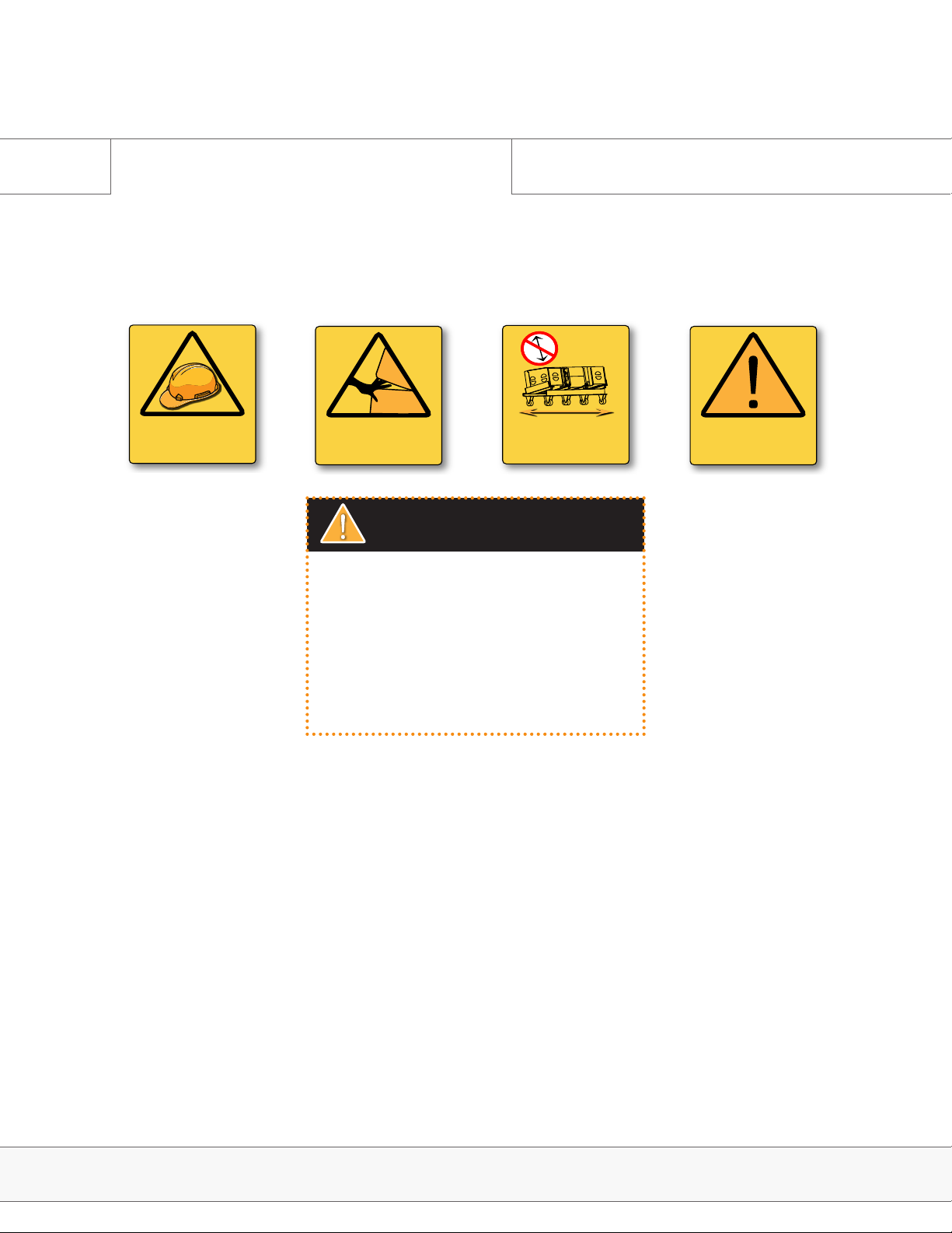
WARNING
SAFETY RISK
PAY SPECIAL ATTENTION
PINCH POINT
CAN CAUSE SEVERE
PERSONAL INJURY
TIP HAZARD
ALWAYS MOVE LOADED
DOLLY ON THE LONG EDGE
ATTENTION
IMPORTANT OPERATING
INSTRUCTIONS
Section A
Warning & Safety Symbols
Throughout this manual the potential risks are indicated by these symbols.
ATTENTION
It is compulsory to read this manual before using
the E-Series system. Supervision and competency
are the responsibility of the system owners and
operators. All intersections, joints and rigging hard
ware must be inspected regularly. Operators must
not assume rigging has been inspected prior to use
by someone else.
-
E-Series | Warning & Safety Symbols
Page 3
Page 4
Section A
Safety Precautions
English
• Read these instructions, keep them available for reference, they can
be downloaded any time from https://www.adamsonsystems.com/
index.php/support . Heed all warnings and follow all instructions.
• Servicing is required when the loudspeaker has been damaged in any
way, such as when the loudspeaker has been dropped; or when for
undetermined reasons the loudspeaker does not operate normally.
• Protect the cabling from being walked on or pinched.
• Use only with the rigging frames/accessories specied by Adamson,
or sold with the loudspeaker system.
• This speaker enclosure is capable of creating a strong magnetic
eld. Please use caution around the enclosure with data storage
devices such as hard drives.
• Handles are for moving the system only.
ATTENTION
IMPORTANT OPERATING
INSTRUCTIONS
Francais
• Lire les instructions ci dessous, maintenez-les disponibles pour
référence. Ils peuvent être téléchargés à tout moment à cette
adresse. https://www.adamsonsystems.com/index.php/support
.Tenez compte de tous les avertissements et suivez toutes les
instructions.
• Une maintenance s’avère nécessaire lorsqu’une enceinte a été
endommagé de quelque façon que ce soit. Que celle ci soit tombé
ou qu’elle ne fonctionne pas normalement pour des raisons
indéterminées.
• Protéger le câblage contre l’écrasement.
• Utiliser uniquement les accessoires d’accrochage fourni par
ADAMSON ou vendu avec les enceintes.
• Cette enceinte acoustique génère des champs magnétiques
intenses. Prenez les précautions nécessaires avec les appareilles de
stockage de données comme les disques durs.
• Les poignées ne doivent servir qu’à déplacer l’enceinte.
Espanol Deutsch
• Lea estas instrucciones y téngalas a mano cuando las necesite.
Puede descargarlas cuando desee desde https://www.
adamsonsystems.com/index.php/support. Preste atención a todas
las recomendaciones y siga las instrucciones.
• Debe reparar el altavoz cuando haya algún desperfecto de cualquier
tipo, por ejemplo cuando haya caído o en ocasiones indeterminadas
en que el altavoz no funcione correctamente.
• Proteja el cableado para que no sea pisado o aplastado.
• Utilice solamente los Rigging Frames y accesorios especicados
por Adamson o que vengan con el equipo original de Adamson.
• Este recinto acústico es capaz de generar fuertes campos
magnéticos. Tenga especial cuidado al utilizar dispositivos de
almacenamiento de datos magnéticos como Discos Duros etc.
• Las agarraderas son solo para mover el sistema.
• Lesen sie diese Anleitung und bewahren Sie sie auf. Sie kann jederzeit
unter https://www.adamsonsystems.com/index.php/support
heruntergeladen werden. Beachten Sie alle Warnungen und folgen
Sie allen Anweisungen.
• Service ist notwendig wenn der Lautsprecher in irgendeiner Art
beschädigt wurde, z.B. weil er heruntergefallen ist oder wenn er aus
anderen Gründen nicht ordnungsgemäß funktioniert.
• Schützen Sie die Lautsprecherkabel davor gequetscht oder geknickt
zu werden.
• Verwenden Sie ausschließlich das von Adamson für dieses
Lautsprechersystem spezizierte bzw. das zusammen mit dem
System erworbene Rigging-Zubehör.
• Dieser Lautsprecher kann ein starkes magnetisches Feld erzeugen.
Bitte seien Sie in der Nähe des Lautsprechers z.B. mit Datenspeichern
wie Festplatten entsprechend vorsichtig .
• Die Griffe dienen ausschließlich zum Transport des Lautsprechers
E-Series | Safety Precautions
Page 4
Page 5

E-Series User Manual
Table of Contents
Sections
Introduction & Product Details
1.1 Overview 6
1.2 Predictive Software 7
1.3 E15 Spec Sheet 8
1.4 E12 Spec Sheet 9
1.5 E218 Spec Sheet 10
1.6 E219 Spec Sheet 11
1.7 Cardioid Subs 12
System Configuration
2.0 E-Rack Description 13
2.1 E-Rack Overview 14
2.2 Configuration Example 15
2.3 Wiring Diagrams 16
Rigging
3.0 The 4 Stack Dolly 18
3.1 Rigging Overview 19
3.2 Rear Rigging 24
3.3 Front Rigging 25
3.4 Rigging Sticker Legend 27
3.5 Setting Angles 28
3.6 Attaching the Rigging Frame 29
3.7 Consequent Arrays 31
3.8 Highly Curved Arrays 33
3.9 Lowering the Array 34
3.10 Rigging the E Sub 35
3.11 Attaching Tops to Subs 36
Ground Stacking
4.0 Ground Stacking Legs 38
Truck Pack
5.0 Possible Configurations 39
E-Series | Table of Contents
Page 5
Page 6

Introduction & Product Details
1.0 Introduction
This manual is designed to give the E-Series user the necessary information to accurately fly or
stack E-Series loudspeakers in all the available congurations, as well as the proper deployment
and use of E-Series loudspeakers. Safe step by step rigging procedures will be outlined, as well
as example system congurations, correct wiring and amplication and transport.
1.1 Overview
At Adamson, we believe that loudspeakers need to be built from the ground up. This means
having total control over every aspect of the design and manufacturing process. The E-Series
is the culmination of decades of research that has allowed us to deliver the highest performing,
large format line array on the planet.
At the heart of the E-Series is the E-Capsule. It houses the patented Co-Linear Drive Module - a
revolutionary dual chamber waveguide concept capable of virtually eliminating mid-frequency
lobing in line source designs. The patented Autolock™ rigging system is mounted to this core
rather than the cabinet exterior. One engineer can set angles and hoist the system in tight
quarters using the smallest and lightest rigging frame in the industry. In true Adamson tradition,
Kevlar cones are essential to the design and a part of an unmistakable sonic signature of
unmatched vocal clarity, power and punch.
We’ve set the modern touring standard by using only rugged, durable and light weight materials.
From Marine Grade Baltic birch to Air Craft Grade aluminium and Kevlar Neodymium drivers.
The entire system is designed to maximize use of space in a standard North American or
European truck pack. It features the fastest and most intuitive rigging system available.
E-Series | Introduction & Product Details
Page 6
Page 7

Introduction & Product Details
1.2 Predictive Software
Blueprint AV
Blueprint AV is a 2D & 3D modeling suite which offers a fast and intuitive work-flow, without sacricing
precision. The E-Series is included, along with all of Adamson’s other Line Array products. Design is simple
and easy, yet complex simulation options are at your nger tips.
Use basic geometric shapes to design anything from a basic eld to a complex structure. Multi-point
extrude and revolve surfaces allow for intuitive arena or stadium design.
Depending on your time constraints, Blueprint AV can be easily switched from in-depth 3D operation to
streamlined 2D operation, saving on simulation time.
Once your hang is designed, Blueprint gives you all pertinent mechanical information needed to correctly
fly the system.
Blueprint AV is now available as a native Java-run program for both PC and Mac platforms. Please contact
blueprint@adamsonsystems.com for license information and technical support.
E-Series | Introduction & Product Details
Page 7
Page 8
Introduction & Product Details
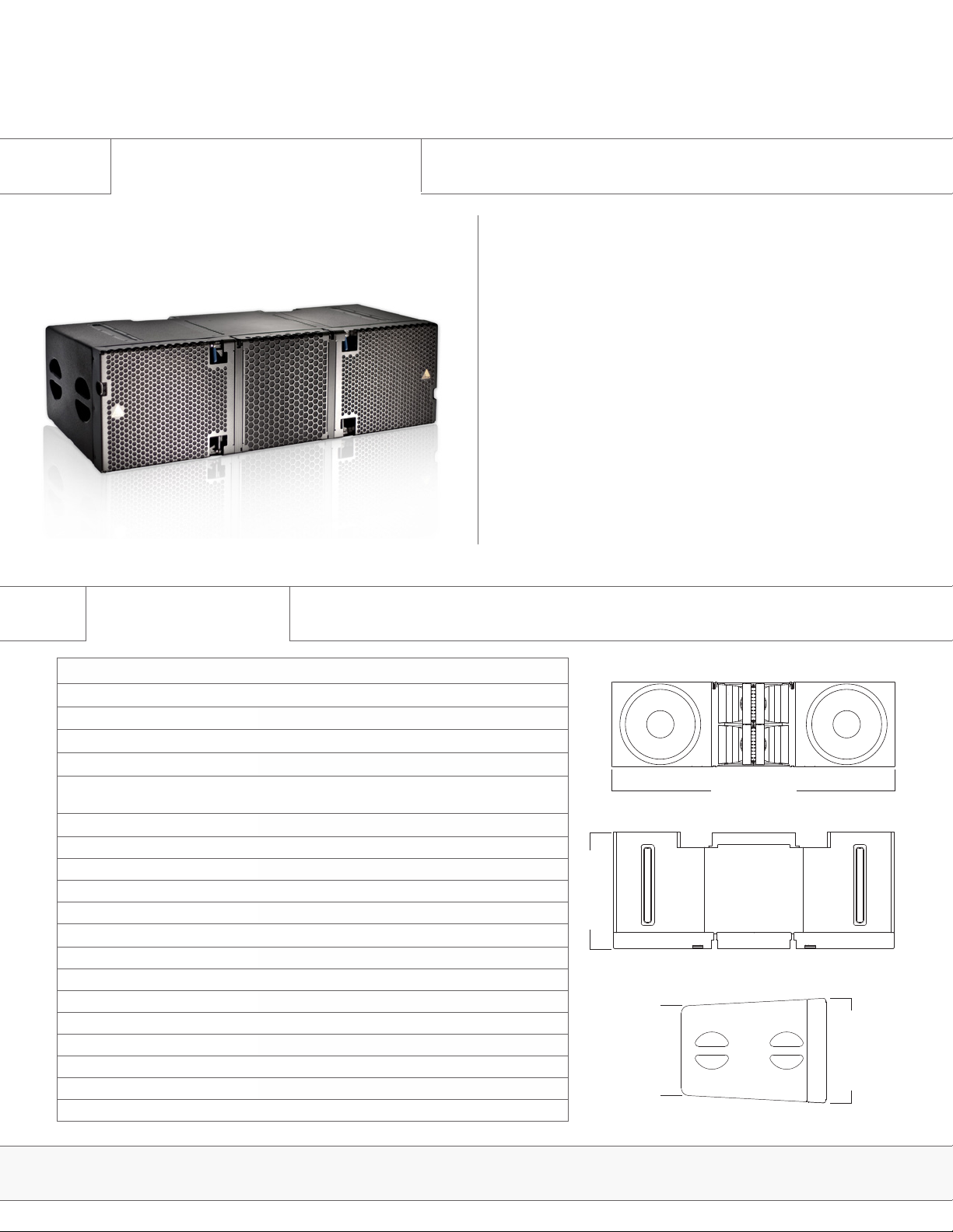
1.3 E15 Spec Sheet
E15
The Adamson E15 is a 3 way, true line source enclosure, incorporating proprietary transducer and waveguide technology which reduces weight and minimizes the footprint. The heart of the E15 is the
E-Capsule, which is precisely engineered and constructed of lightweight
aluminum. The patent pending skeletal structure provides an accurate
and rigid frame for mounting the modular aircraft grade steel Auto-
lock™ rigging system, while simultaneously housing a series of efcient
mid-high components coaxially mounted on Adamson’s pioneering
Co-Linear Drive Modules.
Two vector corrected low-excursion 7” Kevlar Neodymium midrange
transducers paired with two next generation 4” HF compression drivers
energize the drive modules and provide seamless mid-high energy
with no audible distortion at very high SPL levels. Critically optimized
waveguides based on a prolate-spheroidal geometry ensure precise
pattern control and minimum THD, producing a dispersion pattern of
90° x 6° (H x V). The E-Capsule is flanked with two separate birch ply
enclosures, each containing Adamson’s proprietary Kevlar Neodymium
15” woofer, capitalizing on the advantages of Adamson’s Advanced
Cone Architecture and optimized heat dissipation management of the
4” voice coil.
Specications
Frequency Range (+/-3 dB) 60 Hz - 18 kHz
Nominal Directivity (-6 dB) H x V 90° x 6°
Maximum Peak SPL
Components LF 2x ND15-L 15” Kevlar Neodymium Driver
Components MF 2x YX7 7” Kevlar Neodymium Driver
Components HF 2x NH4TA2 4” Diaphragm / 1.5” Exit Compression
Nominal Impedance LF 2x 8 Ω
Nominal Impedance MF 16 Ω
Nominal Impedance HF 16 Ω
Power Handling (AES / Peak) LF 2x 800 / 2x 3200 W
Power Handling (AES / Peak) MF 700 / 2800 W
Power Handling (AES / Peak) HF 320 / 1280 W
Connection 2x Speakon™ NL8
Height Front (mm / in) 391 / 15.4
Height Back (mm / in) 333 / 13.125
Width (mm / in) 1306 / 51.4
Depth (mm / in) 544 / 21.4
Weight (kg / lbs) 79.8 / 176
**
12 dB crest factor pink noise at 1m, free eld, using specied processing and amplication
Processing Lake
**
147 dB
Driver
Rigging Autolock™ Rigging System
1305 mm / 51.4 in
543 mm / 21.4 in
333 mm / 13.125 in
391 mm / 15.4 in
E15 | Spec Sheets
Page 8
Page 9
Introduction & Product Details
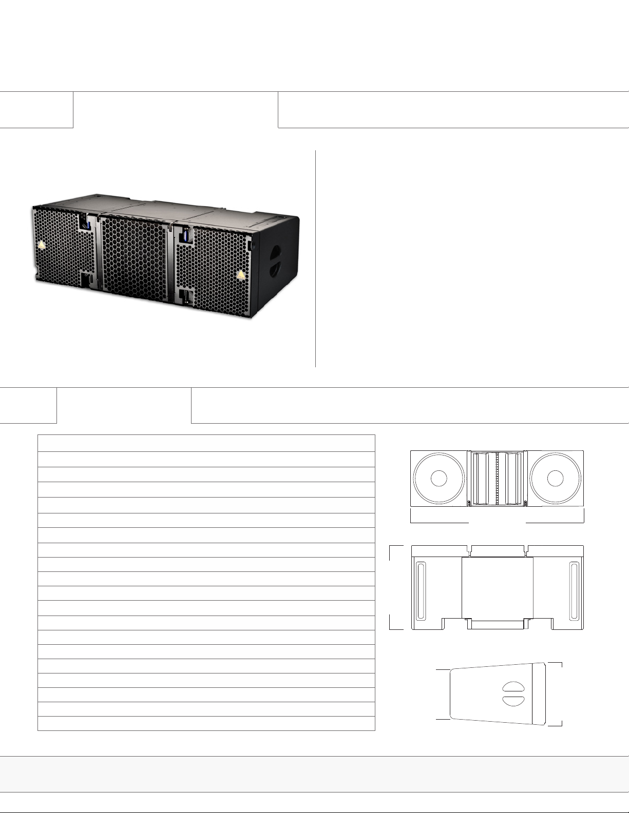
1.4 E12 Spec Sheet
E12
The Adamson E12 is a 3 way, true line source enclosure, incorporating proprietary transducer and waveguide technology which reduces weight and minimizes its footprint. The heart of the E12 is the
E-Capsule, which is precisely engineered and constructed of lightweight
aluminum. The patent pending skeletal structure provides an accurate
and rigid frame for mounting the modular aircraft grade steel Autolock™
rigging system, while simultaneously housing ultra-efcient mid-high
components coaxially mounted on Adamson’s newly modied E12
Co-Linear Drive Module.
A vector corrected low-excursion 7” Kevlar Neodymium midrange
transducer paired with a next generation 4” HF compression driver
energize the drive module and provide seamless mid-high energy with
no audible distortion at very high SPL levels. The critically optimized
waveguide, based on a prolate-spheroidal geometry ensure precise
pattern control and minimum THD, producing a dispersion pattern of
110° x 8° (H x V). The E-Capsule is flanked with two separate birch ply
enclosures, each containing Adamson’s proprietary Kevlar Neodymium
12” woofer, capitalizing on the advantages of Adamson’s Advanced
Cone Architecture and optimized heat dissipation management of the
4” voice coil.
Specications
Frequency Range (+/-3 dB) 60 Hz - 18 kHz
Nominal Directivity (-6 dB) H x V 110° x 8°
Maximum Peak SPL
Components LF 2x ND12-S 12” Kevlar Neodymium Driver
Components MF YX7 7” Kevlar Neodymium Driver
Components HF NH4TA2 4” Diaphragm / 1.5” Exit Compression Driver
Nominal Impedance LF 2x 8 Ω
Nominal Impedance MF 8 Ω
Nominal Impedance HF 8 Ω
Power Handling (AES / Peak) LF 2x 800 / 2x 3200 W
Power Handling (AES / Peak) MF 350 / 1400 W
Power Handling (AES / Peak) HF 160 / 640 W
Connection 2x Speakon™ NL8
Height Front (mm / in) 358 / 14.1
Height Back (mm / in) 282 / 11.1
Width (mm / in) 1111 / 43.75
Depth (mm / in) 543 / 21.4
Weight (kg / lbs) 59.9 / 132
Processing Lake
**
12 dB crest factor pink noise at 1m, free eld, using specied processing and amplication
**
145 dB
Rigging Autolock™ Rigging System
1111 mm / 43.75 in
543 mm / 21.4 in
281 mm / 11.1 in
358 mm / 14.1 in
E12 | Spec Sheets
Page 9
Page 10
Introduction & Product Details
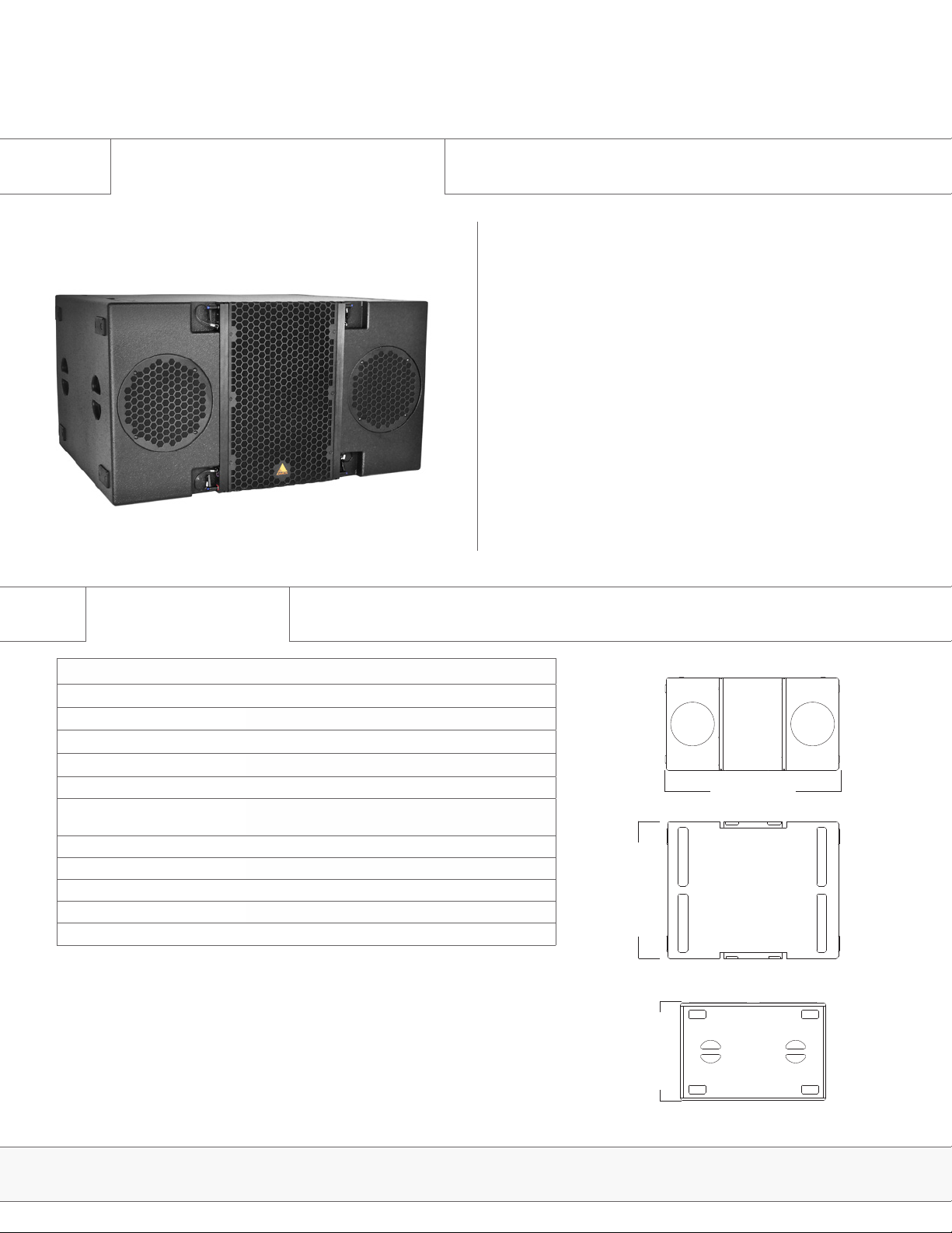
1.5 E218 Spec Sheet
E218
The E218 subwoofer was developed to pair with the E12 or E15
enclosures. Two light-weight, long excursion ND18-S Kevlar Neodymium drivers which utilize Adamson’s Advanced Cone Architecture are
mounted in an efcient band-pass subwoofer. The design achieves a
remarkable reduction of the rearward radiated energy without dedicated
cardioid setups and algorithms. A typical user would appreciate the
sonic attack of this design.
The E218 can be used ground stacked or flown utilizing the E-Frame
Full Line. The frame also allows the E218, E219 and E12/E15 enclosures to be flown in the same array.
The E218 is constructed of (marine) birch plywood as well as aircraft
grade steel and aluminum and is equipped with three Speakon NL8
connectors, two parallel in / out plugs and one dedicated output con-
nection point for efcient cable usage. The integrated rigging system
allows for either 0° or 3° splay between adjacent enclosures.
Specications
Frequency Range (+/- 3dB) 30 Hz - 110 Hz
Maximum Peak SPL
Components LF 2x ND18-S 18” Neodymium Kevlar Driver
Nominal Impedance LF 2x 8 Ω
Power Handling (AES / Peak) LF 2x 800 / 3200 W
Connection 3x Speakon™ NL8: 2x Rear Parallel (Pins 1 +/-) and 1x
Height Front (mm / in) 597 / 23.5
Width (mm / in) 1111 / 43.75
Depth (mm / in) 870 / 34.25
Weight (kg / lbs) 86 / 190
Processing Lake
**
12 dB crest factor pink noise at 1m, half space, using specied processing and amplication
**
142 dB
Rigging Flyable with E-Frame Full Line
Rear Output (Pin 2 to 1)
1111 mm / 43.75 in
870 mm / 34.25 in
597 mm / 23.5 in
Page 10E218 | Spec Sheets
Page 11
Introduction & Product Details
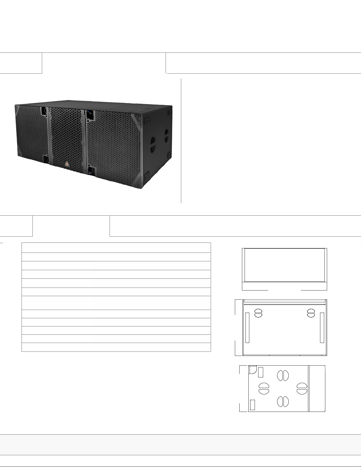
1.6 E219 Spec Sheet
E219
The E219 Subwoofer was developed to bolster the low-end of the
E-Series line of products. The enclosure is loaded with two light weight,
long excursion, 19” SD19 Kevlar Neodymium drivers utilizing Adamson’s Advanced Cone Architecture and Symmetrical Drive Technology.
The drivers employ dual 5” voice coils for exceptional power handling,
with a dual-spider suspension system for extra stability even under
extreme excursion. They are mounted in an ultra-efcient front-loaded
enclosure, designed to reproduce clean, musical low frequency information. A typical user would appreciate the lower fundamental notes of
this design.
The E219 can be ground stacked or flown utilizing the E-Frame FUll
Line. The cabinet construction uses marine grade birch plywood as
well as aircraft grade steel and aluminum, and is equipped with three
Speakon™ NL8 connectors, two parallel In/Out plugs and one dedicated
output connection to optimize speaker cabling. The integrated rigging
system allows for either 0° or 3° splay between adjacent cabinets.
Specications
Frequency Range (+/- 3dB) 28 Hz - 90 Hz
Maximum Peak SPL
Components LF 2x SD19 19” Kevlar Neodymium Driver
Nominal Impedance LF 2x 5 Ω
Power Handling (AES / Peak) LF 2x 1600 / 2x 6400 W
Connection 3x Speakon™ NL8: 2x Rear Parallel (Pins 1 +/-) and 1x
Height Front (mm / in) 597 / 23.5
Width (mm / in) 1418 / 55.83
Depth (mm / in) 889 / 35
Weight (kg / lbs) 112.9 / 249
Supported Processing Lake
**
12 dB crest factor pink noise at 1m, half space, using specied processing and amplication
**
144 dB
Rigging Flyable with E-Frame Full Line
Rear Output (Pin 2 to 1)
1418 mm / 55.83 in
889 mm / 35 in
597 mm / 23.5 in
Page 11E219 | Spec Sheets
Page 12
Introduction & Product Details
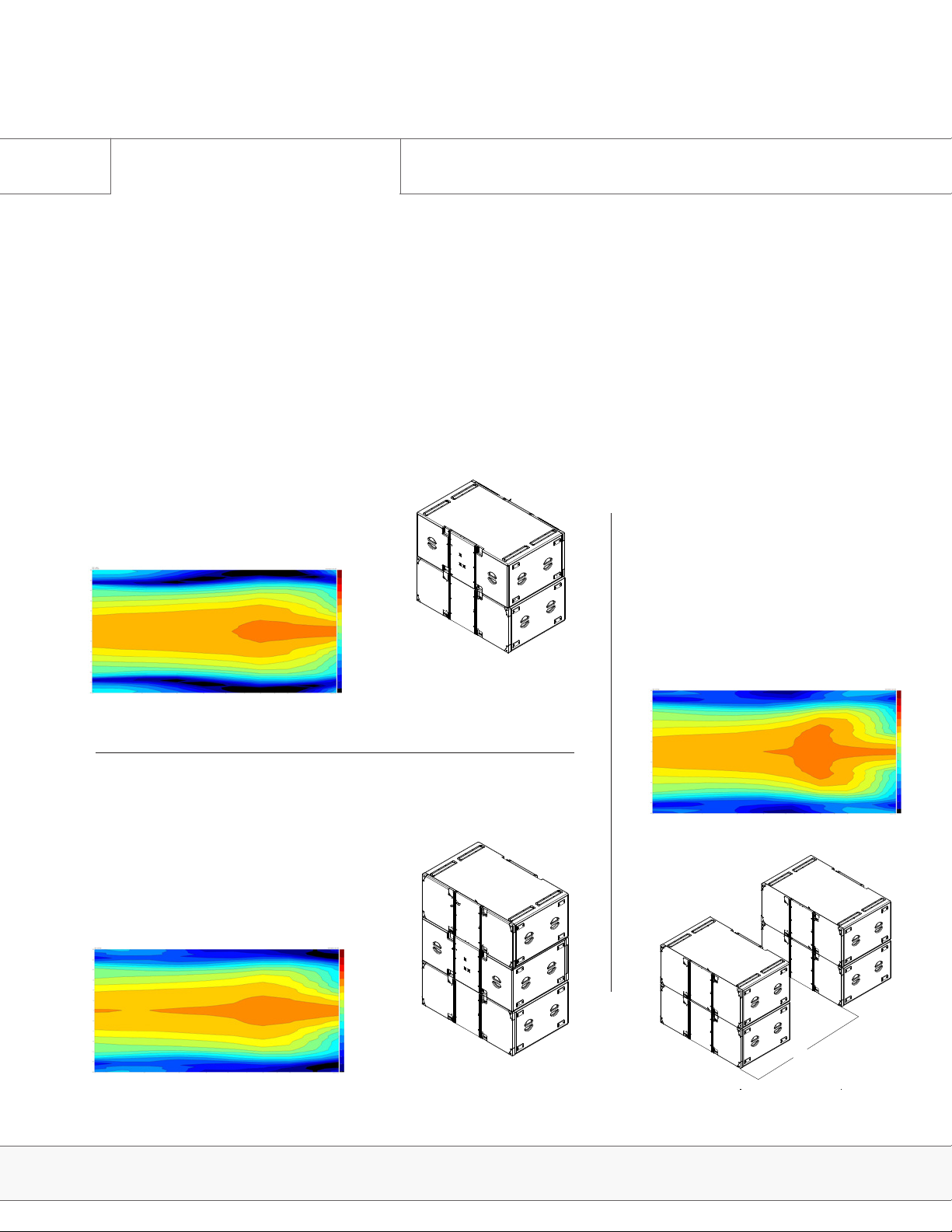
1.7 Cardioid Subs
Every Adamson subwoofer has specifically designed cardioid presets. Adamson utilizes three
configurations ranging from a minimal footprint and minimized rear rejection to larger setups
that eliminate virtually all audio energy behind the array. Please refer to the Lake Preset Loading
Manual for further instructions.
Front-Back
The FB preset should be used in situations
where a minimal footprint is desired.
Only 2 enclosures stacked ensures that
sightlines will not be impaired.
End-Fire 66
The EF66 preset should be used
in situations where the most
rear cancellation is desired.
Unlike traditional end-fire
arrays, Adamson’s proprietary
preset eliminates a wide range
of frequencies in the rear of the
array.
Front-Back-Front
The FBF preset exhibits higher output from
the front of the array. A similar footprint
to the FB configuration, this stack is 3
enclosures high.
E-Series | Cardioid Subs
66"
Page 12
Page 13

System Conguration
2.0 E-Rack Description
Adamson Touring Rack
Adamson has developed a unified
rack solution, configured to
interface seamlessly with our line of
loudspeaker products. All E-Racks
are equipped with two or three Lab.
gruppen PLM+ series amplifiers,
featuring Lake processing and Dante
audio networking functionality. The
Adamson Audio Panel provides
Analog and AES inputs, Speakon NL8
and Socapex outputs, and etherCON
RJ45 connections, designed for dual
redundant Dante setups. A managed
Gigabit Ethernet switch and an AC
distribution panel available in 120
V or 230 V versions complete the
hardware. The entire package fits into
a compact and lightweight 10U rack,
designed with interior suspension,
hinged doors and extra rails for
secure & efficient use of space.
E-Rack elements are comprised of:
• 10U suspended rack with hinged, sliding front and rear doors
• Up to three Lab.gruppen PLM 20K44 ampliers (8 and 12-Channel versions available)
• Adamson Audio Panel
• Adamson AC Panel, 120 V or 230 V (region specic)
• Cisco SG300-20 managed switch
• Includes one Personal License per rack
E-Series | System Conguration
Page 13
Page 14

System Conguration
2.1 E-Rack Overview
Adamson has developed a unied rack solution congured to interface seamlessly with our
line of Loudspeaker products. For more information on the E-Rack, please refer to the E-Rack
brochure available on the Adamson Systems website.
2 or 3x Lab.gruppen PLM 20K44
1x Adamson Audio Panel, incl. Analog and
PUSHPUSHPUSH
PUSHPUSHPUSH
AES in and thru-puts (XLR), Speaker outputs (NL8 and Socapex), Gigabit Network
Ports (Ethercon RJ45)
1x AC Distribution Panel, L21-30 input or
CEE 32A 3-Phase 400V/230V 3L+N+PE
(Red CEE connector), depending on region
1x DANTE Certied Switch (Rear Side)
E-Series | System Conguration
Page 14
Page 15

System Conguration
2.2 Configuration Example
This example conguration demonstrates the efciency of the system. For further information regarding congurations, please refer to the Adamson Document E-Series Conguration Brochure.
E12 | System Conguration
Page 15
Page 16

System Conguration
2.3 Wiring Diagrams
E12
3-way line source enclosure [974-0001]
LF - 2x 12” ND12-S[940-0022], MF - 1x 7” YX7 [940-0020], HF - 1x 4”NH4 [140-0004]
Autolock™ rigging system
E15
3-way line source enclosure [975-0001]
LF - 2x 15” ND14-L[940-0013], MF - 2x 7” YX7 [940-0020], HF - 2x 4”NH4 [140-0004]
Autolock™ rigging system
E-Series | Wiring Diagrams
Page 16
Page 17

System Conguration
2.3 Wiring Diagrams
E218
[992-0007]
Subwoofer: LF - 2x 18” ND18-S [940-0023]
Integrated rigging system
E219
[994-0001]
Subwoofer: LF - 2x 19” SD19-ND [940-0024]
Integrated rigging system
E-Series | Wiring Diagrams
Page 17
Page 18

Rigging
3.0 The 4 Stack Dolly
Transporting the 4 Stack Dolly
There is a tip hazard when transporting a 4 stack on uneven ground or on a ramp. To avoid tipping the dolly,
It should always travel with sides of the cabinet to the front or back.
*On the 4 stack dolly, the bottom cabinet is held in place by the rear, red autolock mechanism..
TIP HAZARD
ALWAYS MOVE LOADED
DOLLY ON THE LONG EDGE
E-Series | Rigging
Page 18
Page 19

Rigging
3.1 Rigging Overview
TIP HAZARD
ALWAYS MOVE LOADED
DOLLY ON THE LONG EDGE
The Autolock Rigging System™
The Autolock Rigging System™ is the main attachment for all of the points in the E15/E12 system. The idea is
to only guide the latches to the right spot, where a spring-loaded bolt snaps into place, and is then secured with
the very same lever by turning it into its lock down position. Caution should be taken while connecting cabinets to
ensure hands are out of the way.
The order of operation of the rigging system is: prep angles, arm pins, guide into place (pinning happens
automatically) and secure rigging parts manually to ‘closed’ position.
The levers are color coded for ease of use. All front rigging have black levers at bottom and and blue levers on top,
the rear levers are red.
The black bottom levers hold and release the rigging bar from the
box above, the blue top lever receives the rigging frame, as well as
the above box’s rigging bars and locks them into place. The black
lever only has one function; to release rigging bar either to put into
use or to store it away. Pull it to release, let it go and it flips back
into place.
Fig. 1
The Autolock™ Rigging features a ‘peep
hole’ where you can see the rigging bar
when it is locked. When it is unlocked you
will see a clear avenue. To be sure, make
sure you can set all blue and red levers to
‘Closed’ position (down).
The blue and red levers have 3 functions: Closed, Spring, and Open.
(pages 25-26)
All rigging levers feature a ‘peep hole’(Fig. 1) where you can assure
the the pin is fully ejected and is in fact in its proper place. Always
make sure your red and blue levers are set to ‘Closed’ position.
E-Series | Rigging
Page 19
Page 20

Rigging
3.1 Rigging Overview
ATTENTION
IMPORTANT OPERATING
INSTRUCTIONS
The rear of the E-Capsule also features an angle chart
with a knob lever which adjusts the angles. (Fig. 2) All
angles are set while the cabinets are stacked on the dolly,
ensuring that a single technician can prep the cabinets
for rigging. For a more detailed look at the rigging sticker,
please refer to section 3.4.
Fig. 2
0 0°
1 0.5°
2 1.0°
3 2.0°
4 3.0°
5 4.5°
6 6.3°
7 8°
in enclosure
R
Fig. 3 E12 E15Fig. 4
E-Series | Rigging
0 0°
1 0.3°
2 0.6°
3 1.3°
4 2.0°
5 3.1°
6 4.4°
7 6°
in enclosure
R
There are 8 angles, 0 to 7, and an additional ‘R’ being the
‘idle’ or ‘rest’ position, when the rigging hardware is all the
way down and the boxes aren’t connected. It is applicable
when the enclosure is not in use, to protect the rigging
hardware from damage. To keep the system intact for
transport, leave the angles pinned in.
The angles are numbered as well as color coded to mark
which slot should be pinned with the attached push-pin.
The following rigging positions are equal to the following
degrees for the E12 (Fig. 3) and the E15 (Fig.4).
Page 20
Page 21

Rigging
3.1 Rigging Overview
ATTENTION
IMPORTANT OPERATING
INSTRUCTIONS
The E-Frame with Extender Beam is designed for use with the E12 and E15 cabinets. It
consists of a steel frame, paired with an extension beamof which there are several combination
congurations. Always refer to Blueprint AV™ for correct rigging instructions.
In standalone mode (Fig. 1), the frame can be
used to lift flat to slightly-angled arrays. Two
rigging plates are provided for dual motor
operation, and if two motors are not available,
one lifting plate may be repositioned towards
the center of the frame. Please refer to
Blueprint AV™ when determining proper lifting
plate location.
Fig. 1
Fig. 2
In order to attach the extended beam, the
lifting plates must be removed and replaced
with Extended Beam plates, characterized as
having a rectangular shape and two smaller
holes at the top of each plate. (Fig. 2)
As arrays get longer and more curved, the
center of gravity will shift, making it necessary to position the rigging beam and rigging
pieces so that the motors carry equivalent
weight. The ‘Mechanical’ tab in Blueprint AV™
will aid the user in choosing the correct rig-
ging frame conguration. (Fig. 3)
Fig. 3
E-Series | Rigging
Page 21
Page 22

Rigging
3.1 Rigging Overview
ATTENTION
IMPORTANT OPERATING
INSTRUCTIONS
For arrays with little to no
incline, the extension beam
centered will usually provide
the best weight dispersion.
Fig. 1
Fig. 2
Fig. 3
For arrays with negative incline,
the extension beam positioned
towards the back of the frame
will provide the best weight
dispersion.
For arrays with positive incline,
the extension beam positioned
towards the front of the frame
will provide the best weight
dispersion.
E-Series | Rigging
Page 22
Page 23

Rigging
3.1 Rigging Overview
The E-Frame Full Range is designed for use with all E-Series enclosures. It consists of a steel
frame, long enough to not need the addition of an extension beam. It can be congured as
a standalone frame to hang any cabinet, or as an adapter frame to hang top cabinets under
flown subs, or to stack top cabinets on ground stacked subs. Always refer to Blueprint AV™ for
correct rigging instructions.
ATTENTION
IMPORTANT OPERATING
INSTRUCTIONS
The frame faces one direction while in stacking mode and is reversed when in hanging mode. If
the E218/E219 and E12/E15 are to be flown in the same array, two frames are needed. Please
refer to sections 3.10 and 3.11 for detailed descriptions of how to deploy the frame.
E-Series | Rigging
Page 23
Page 24

Rigging
3.2 Rear Rigging
Rear Autolock Rigging - Red Lever
The 3 different modes of the red lever:
1. Closed (Locked)
2. Spring Mode
3. Open (Locked)
Fig. 1
ATTENTION
IMPORTANT OPERATING
INSTRUCTIONS
In the ‘Closed’ mode (Fig. 1) the lever is in and turned
upward or downward (both up and down lock the
system - decide which way you’ll be using it, and close
all the enclosures the same way for uniformity.
Fig. 2
Fig. 3
The lever is pulled out and parallel to the ground in
‘Spring’ mode (Fig. 2)
The lever is out and turned downward or upward in
‘Open’ mode (Fig. 3). This mode is used when taking
the system down ie on boxes 4-8-12-16... This mode
can also be used on all enclosures when separating
4-stacks into individual enclosures.
E-Series | Rigging
Page 24
Page 25

Rigging
3.3 Front Rigging
Front Autolock Rigging - Blue Lever
The 3 different modes of the blue lever:
1. Closed (Locked)
2. Spring Mode
3. Open (Locked)
Fig. 1
ATTENTION
IMPORTANT OPERATING
INSTRUCTIONS
‘Closed’ (Fig. 1)- the lever is in and turned downward to
lock the system.
Fig. 2
Fig. 3
The lever is pulled out and parallel to the ground in ‘Spring’
mode (Fig. 2)
The lever is pulled out and turned downward. This ‘Open’
mode (Fig. 3) is used in taking the system apart. ie on
boxes 1-5-9-13. Also on all enclosures when separating 4
stacks for maintenance etc.
E-Series | Rigging
Page 25
Page 26

Rigging
3.3 Front Rigging
Front Autolock Rigging - Black Lever
There is only 1 mode of use for the black lever:
Fig. 1
ATTENTION
IMPORTANT OPERATING
INSTRUCTIONS
The lever is pulled out and parallel to the ground in temporary
‘Open’ mode (Fig. 1)- this releases the rigging bars from
inside the enclosure. The lever snaps back into place ready to
be fastened to ’Closed’ mode. To place the rigging bars back
into the enclosure just pull lever out again and push gear back
into place.
Fig. 2
Make sure system is fully fastened in the ‘Closed’ mode
(Fig.2) by using the ‘peep hole’ prior to lifting.
E-Series | Rigging
Page 26
Page 27

Rigging
3.4 Rigging Sticker Legend
Rear Autolock Rigging Sticker Legend
* When releasing and pulling the system apart (to enclose rigging bars) let
knob slide down to ‘rest’ position (green), and place attached push pin to green
slot (above) If you’re dividing into 4 stacks, perform this task on every 4th box
only.
* When needing a zero degrees angle (such as the top boxes of longer arrays)
use magenta slot. Position 1 uses the purple slot, positions 2 and 4 use the
yellow slot, position 3 uses the blue slot, positions 5 and 7 use the green slot
and position 6 uses the beige slot.
ATTENTION
IMPORTANT OPERATING
INSTRUCTIONS
* Idle Stack Pin slot is used when stacking mode is not in use. It is also used in
a hanging rigging conguration where gravity allows all the angles to shift to
the desired position.
* Stack pin slot is used when stacking the E15/E12 system, or needing a rigid
flown array. (ie when the system is arrayed in a manner that gravity cannot
sustain the desired angles). The user must ensure this pin is set on both sides
of each cabinet.
Note: E12 sticker shown
E-Series | Rigging
Page 27
Page 28

Rigging
3.5 Setting Angles
ATTENTION
IMPORTANT OPERATING
INSTRUCTIONS
Setting the angles on all 4-stacks and basic preparation.
Before attaching cabinets together, use Blueprint AV™ to plan your cabinet angles for desired coverage. Prepare all
the cabinet angles before beginning to attach and lift the array. The top cabinet, which attaches to the rigging frame
is number 1, and the cabinets gain numerically as the descend. Make sure you are setting the correct angle on both
sides of the E-Capsule.
1. The front blue levers on the top cabinets of each 4-up dolly are on
‘Spring’ mode.
2. Red levers in the rear on the BOTTOM cabinet of each 4-stack are in
‘Spring’ mode, abling the hook-up of the next cabinet stack.
3. Remove the angle pin. (Fig. 1)
Fig. 1
4. Raise the sliding knob to the angle specied by corresponding
Blueprint AV design and place the angle pin in the corresponding colorcoded slot. (Fig. 2)
Fig. 2
Fig. 3
Fig. 4
E-Series | Rigging
5. Remember to check that all cabinets are fully bolted through and
locked by conrming that all levers can be placed in ‘Closed’ mode.
(Fig. 3) Make sure to perform this every time even with enclosures
which are already pinned, to guarantee than no one has changed the
mode of the levers during set-up, tear-down or transport.
6. Stack pin should always be in “Idle Stack Pin” mode unless you’re
ground stacking the system or need a rigid array.(Fig. 4)
Page 28
Page 29

Rigging
3.6 Attaching the Rigging Frame
The rigging Frame contains 4 pins: 2 in the front which are xed in place and 2 in the rear, one of which needs to be
pinned manually using attached push pin. The system ideally uses 2 motors: one in front, one in back of the frame
for easy adjustment once the array has been flown. For flying from a single point, you’ll need to rmly decide the
angle of the frame prior to rigging all the cabinets.
1. Place top enclosure’s blue levers to ‘Spring’ position on both sides.
2. The rear angle should be set to “2” or “Yellow” to successfully
connect the top box to the rigging frame.
3. Lower frame and guide the front rigging to place. (Fig. 1)
Fig. 1
PINCH POINT
CAN CAUSE SEVERE
PERSONAL INJURY
WARNING
SAFETY RISK
PAY SPECIAL ATTENTION
Fig. 2
E-Series | Rigging
4. Conrm through peephole that front rigging is locked into place,
and the levers (blue) on both sides of the enclosure are in ‘Locked’
position.
5. Manually pin rear of frame to rst enclosure using attached push
pin. (Fig. 2)
Page 29
Page 30

Rigging
Fig. 3
3.6 Attaching the Rigging Frame
6. Ensure the rear red pin that connects to the dolly on the bottom
cabinet is in the open position. (Fig. 3)
PINCH POINT
CAN CAUSE SEVERE
PERSONAL INJURY
WARNING
SAFETY RISK
PAY SPECIAL ATTENTION
Fig. 4
E-Series | Rigging
7. Lift cabinet stack up, release and lift off dolly. (Fig. 4)
Page 30
Page 31

Rigging
3.7 Consequent Arrays
Fig. 1
PINCH POINT
CAN CAUSE SEVERE
PERSONAL INJURY
WARNING
SAFETY RISK
PAY SPECIAL ATTENTION
Attaching the second and consequent arrays
1. Lift Frame with the attached 4 enclosures high enough to clear the
next 4 -stack underneath. (they should all have their angles set)
2. Place rear rigging (red levers on box #4, 8, 12, 16...28) to ‘Spring’
mode, make sure the same cabinets’ front rigging bars are released
using black levers. (Fig. 1)
Fig. 2
Fig. 3
3. Place front rigging’s blue levers (box #5, 9, 13, 17...29)... (rst box in
the new 4-stack to be suspended) to ‘Spring’ mode (Fig. 2)
4. Pull front rigging’s black lever (box #4,8,12,16...28) allowing the
rigging piece to drop. (Fig. 3)
E-Series | Rigging
Page 31
Page 32

Rigging
Fig. 4
3.7 Consequent Arrays
PINCH POINT
CAN CAUSE SEVERE
PERSONAL INJURY
5. If dealing with a large amount of cabinets and high rigging
points, its best to keep the lower stack pushed slightly back to
allow for any spring in the motor and top rigging. Trying to lower
an array that is not lined up properly can damage the cabinets.
Once the upper array is at the desired position, wheel the lower
stack into position so the front rigging points are lined up in the
slot. Lower the front of the cabinets until the rigging latches
catch, and continue to lower until the rear pin latches. (Fig. 4)
WARNING
SAFETY RISK
PAY SPECIAL ATTENTION
6. Place all levers to ‘Closed’ position. (Fig. 5,6 &7)
7. Make sure that all rigging is latched properly through the
‘peephole’ or by conrming that all levers are in ‘Closed’ mode.
8. Continue and repeat process until you have hung the total
amount of desired cabinets.
Fig. 5
Fig. 6 Fig. 7
E-Series | Rigging
Page 32
Page 33

Rigging
3.8 Highly Curved Arrays
Connecting a 4 stack to a highly curved array
When connecting a 4 stack of cabinets to a steep flown array,
it may not be safe or practical to continue to lower the array to
make the rear attachment (once the fronts are connected). It is
also not recommended to tip the lower dolly forward as this can
be dangerous. The easiest connection method is as follows:
1. Place ALL rear red levers on the 4 stack on the ground to the
“open” position. (Fig. 1)
Fig. 1
PINCH POINT
CAN CAUSE SEVERE
PERSONAL INJURY
WARNING
SAFETY RISK
PAY SPECIAL ATTENTION
Fig. 2
Fig. 3
2. Set the front blue levers on the top cabinet of the 4 stack to the
“Spring” position (Fig. 2)
3. Connect the front of the upper array to the 4 Stack in the same
manner as outlined in section 3.7, #5.
4. Lift the motor slightly so that there is minimal weight on the
dolly of the 4 stack - without actually lifting the dolly from the
ground
5. Ensure the rear red lever on the bottom cabinet of the flown
array is set to “spring” mode. (Fig. 3) Lift the top cabinet in the
stack by hand, so it meets the upper array. The rear red lever
should automatically latch in place. This should be relatively easy
with two people. If the cabinet seems very heavy- there is too
much weight on the cabinet- and the motors must be raised
slightly.
6. Set the next rear red lever to “spring” mode
7. Repeat steps 4-6 until all cabinets are connected at the rear.
NOTE: With enough stage hands, this process can be carried out
with two cabinets at a time- meaning only the red lever connecting
the backs of the 2nd & 3rd cabinet need be disconnected. Please
ensure safe lifting practices are being adhered to to avoid injury.
If straining to lift cabinets - use more stage hands or try lifting the
motors slightly.
E-Series | Rigging
Page 33
Page 34

Rigging
3.9 Lowering the Array
Fig. 1
Fig. 2 Fig. 3
PINCH POINT
CAN CAUSE SEVERE
PERSONAL INJURY
WARNING
SAFETY RISK
PAY SPECIAL ATTENTION
To Lower a Steep Angled Array
1. Lower the array until it is just above the floor. (Fig. 1)
2. Make sure the rear red lever on the bottom box is set to “spring” mode
to receive the dolly.
3. Connect the dolly to the bottom cabinet.
4. If the bottom cabinets are at a steep angle and it is unsafe to continue
to lower the array, two crew members should be used to support the
weight of the cabinet at all times; before the dolly has ground contact,
(the dolly should never tip over as in (Fig. 3) push the hang to the front
in order to prevent the dolly to tip over, then proceed lowering the array
(Fig.2); release the red lever above this cabinet to free the rear of the
bottom cabinet.
5. All front levers should stay connected. This will allow you to raise the
motors until the frame is no longer steeply angled. (Fig. 4)
6. Set front blue lever on top cabinet in 4 stack to open. and allow the
bottom 4 cabinets to separate from the array.
7. Lift the array just above the 4 stack and wheel 4 stack out from under
array. (Fig. 5)
Fig. 4
Fig. 5
Fig. 6
If the bottom cabinet in the array is still at a steep angle - repeat this
procedure.
To Lower a Moderately Angled Array
1. Lower the array till it is just above the floor. (Fig. 1)
2. Make sure the rear red lever on the bottom box is set to “spring” mode
to receive the dolly.
3. Connect the dolly to the bottom cabinet.
4. Lower the array till all the rear angles collapse in the bottom 4 stack.
5. Set the front blue lever on the top enclosure of the 4 stack to open.
6. Set the rear red lever on the bottom of the upper array to open.
7. Lift the array above the 4 stack (Fig. 5)
8. Wheel 4 stack out of the way
Repeat procedure until done. (Fig. 6)
E-Series | Rigging
Page 34
Page 35

Rigging
3.10 Rigging the E Sub
The E218 an E219 rigging system is based on the same concept as the Energia Autolock™ system, but simplied. A
less complex system without spring loaded locking mechanisms allows the user to quickly connect and fly a multitude
of E-Series Subwoofer cabinets.
The E-Frame Full Line has two modes; flying and stacking. A tray for the Adamson Laser Inclinometer exists at one
end of the frame. If the tray is facing forward, the frame is in flying mode. If the tray is facing backwards, the frame
is in stacking mode.
Four rigging pieces drop down from the center capsule to connect
another E218, E219 , or an E-Frame Full Line to adapt for use with
an E12 as well. Four chambers at the top of the center capsule
allow connection between 2 E218 Steps to rigging the E-Series
Subwoofers:
1. Set the angle of all cabinets to be flown to either 0° or 3° splay, as
specied in your Blueprint AV™ design. (Note that in order to connect
the top box to the rigging frame, the angle must be set to 0°)
2. Attach the E-Frame Full Line to the top E218 or E219 cabinet and
secure in place with the push pins provided (Fig. 1)
Fig. 1
PINCH POINT
CAN CAUSE SEVERE
PERSONAL INJURY
WARNING
SAFETY RISK
PAY SPECIAL ATTENTION
Fig. 2
Fig. 3
3. Due to the depth of the E-Frame Full Line, no external beam is
needed. Attach rigging plates to the rigging frame in the positions
specied in the Mechanical page of your Blueprint AV™ design.
(Fig. 2)
4. Lift the Frame with the E-Series Subwoofer attached. (Fig. 3) If
more E218 or 219 are to be flown, repeat step 1 for the next dolly,
lower the already rigged Subwoofers to the next set, position the
rigging pieces and secure them using the push pins.
E-Series | Rigging
Page 35
Page 36

Rigging
3.11 Attaching Tops to Subs
The E-Frame Full Line is designed to allow all members of the E-Series family to be safely rigged to one another,
whether it is in a ground-stacked or flown scenario.
PINCH POINT
CAN CAUSE SEVERE
PERSONAL INJURY
WARNING
SAFETY RISK
PAY SPECIAL ATTENTION
Ground Stacked
1. Place E218 cabinets where the Blueprint AV™ design
species.
2. Attach the E-Frame Full Line to the top E218 cabinet and secure in place with the push pins provided with the E218. (Fig. 1)
Fig. 1
3. Make sure the Stacking Plates are in the up position, and secured with the push pins provided. The position of the Stacking
Plates is adjustable, follow what the Blueprint AV™ mechanical
tab displays. (Fig. 2)
Fig. 2
Fig. 3
Fig. 4
4. Set the E12/E15 red lever to “Spring” mode and place the
cabinet on the rigging frame, conrm the rear rigging is locked.
(Fig. 3)
5.Release the front rigging pieces by opening the black levers on
the front of the E12/E15.
6. Secure in place to the E-Frame Full Line using the top, front
push pin. (Fig. 4)
7. Add cabinets as specied by the Blueprint AV™ design.
E-Series | Rigging
Page 36
Page 37

Rigging
3.11 Attaching Tops to Subs
Note: The steps in section 3.10 must be complete before going any further
PINCH POINT
E12 / E15 as an Underhang
Pictures shown are E12 and E218, the same principles apply to
the E15 and E219.
1. Set all E12 angles while still on the dolly.
2. Set blue levers on the top E12 box to ‘Spring’ mode.
3. Move front lower rigging pieces on the E-Frame Full Line to the
inner channel and secure in place with the push pins provided.
Fig. 1
Fig. 2
(Fig. 1)
4. Place E-Frame Full Line on the E12 and conrm the front rigging is locked.
5. Set the rear knob lever to 0 and lock in place using the push pin.
(Fig. 2)
6. Remove Rigging and Stacking Plates from the Energia Modular
Rigging Frame.
7. Release the lower rigging pieces of the suspended E218 and
remove the upper push pin from each corner of the E-Frame Full
Line. (Fig. 3)
CAN CAUSE SEVERE
PERSONAL INJURY
WARNING
SAFETY RISK
PAY SPECIAL ATTENTION
Fig. 3
Fig. 4
E-Series | Rigging
8. Lower and guide the suspended E218 onto the rigging frame,
securing the rigging pieces to the E-Frame Full Line, using the
push pins previously removed. (Fig. 4)
9. Lift the array and add full range enclosures as specied by
Blueprint AV™ (Fig. 5)
Fig. 5
Page 37
Page 38

Ground Stacking
4.0 Ground Stacking Legs
Dolly Stacking Legs (938-0014)
Fig. 1
TIP HAZARD
ALWAYS MOVE LOADED
DOLLY ON THE LONG EDGE
Available as an accessory, the Ground Stacking Legs allow users
to angle the E12 or E15 in positive or negative increments while
situated on the E12 or E15 Dolly.
1. Make sure all wheel locks are engaged and the dolly is situated
where the design has specied.
2. Insert stacking leg into rectangular chamber directly above the
dolly wheel. (Fig. 1)
3. Insert rst push pin into the hole directly above the dolly wheel. (Fig.
2)
4. Insert second push pin into the hole above and behind the dolly
wheel. (Fig. 3)
5. Repeat procedure for all four stacking legs.
6. Turn handle until all stacking legs are rmly planted on the ground.
(Fig. 4)
7. If a negative inclination is desired, tighten the back two stacking legs
until desired incline is achieved.
8. If a positive inclination is desired, tighten the front two stacking legs
until desired incline is achieved. (Fig. 5)
Fig. 2
Fig. 3 Fig. 4 Fig. 5
E-Series | Ground Stacking Conguration
Page 38
Page 39

Truck Pack
63.8"
92.9"
45.3"
2.4m
1.2m
92.9"
2.4m
1.6m
76.5"
99.4"
45"
63.8"
92.9"
45.3"
2.5m
1.9m
99.4"
2.5m
1.1m
2.4m
1.2m
92.9"
2.4m
1.6m
90.8"
5.0 Possible Congurations
The E-Series system has been designed to t standard truck widths in several different congu-
rations. This section shows some of the options.
90.8"
2.3m
36.3"
76.5"
0.9m
2x E218 Wide
Two 3-high E218 dollies are tight packed end-to end
for a width of approximately 91”, and a depth of approximately 36”.
1.9m
4x E12/E15 Symmetrical
Four 4-high E12 dollies are packed front to back
for a width of approximately 93”, and a depth of
approximately 45”.
2x E218, 1 x E12
Two 3-high E218 dollies flank a single 4-high E12
dolly with a width of approximately 99” and a depth of
approximately 45”.
E-Series | Truck Pack
Page 39
Page 40

 Loading...