

Page 1
Page 2

Adamson Systems Engineering
Blueprint AV Training Module
Blueprint AV is a 2D / 3D modeling suite that provides precise audio performance data within a fast
and efcient workspace. Pre-loaded with acoustic and mechanical data from Adamson’s product
line, Blueprint AV is the ultimate simulation tool to ensure that your Adamson loudspeaker system is
deployed properly and efciently. This guide aims to familiarize the end user with the correct use of
the Blueprint AV program.
Disclaimer: Blueprint AV will show mechanical information relating to working loads. Safe lifting and
suspension of those loads is under the direction and authority of others beyond the jurisdiction, responsibility and control of Adamson Systems Engineering.
Page 3

Table of Contents
Blueprint AV Training Module
Section A: Setting Up Basic 2D Workspace......................................................................................4
Section B: Designing 2D Surfaces.......................................................................................................6
Section C: Cabinet Selection..................................................................................................................9
Section D: Mechanical Page View........................................................................................................15
Section E: 3D Mode Surface Design...................................................................................................16
Section F: 3D Mode Complex Surface Design.................................................................................21
Section G: Complex Cabinet Placement and Simulation............................................................29
Adamson Systems Engineering | Blueprint Training Module
Page 3
Page 4
Section A:
Setting up basic 2D workspace
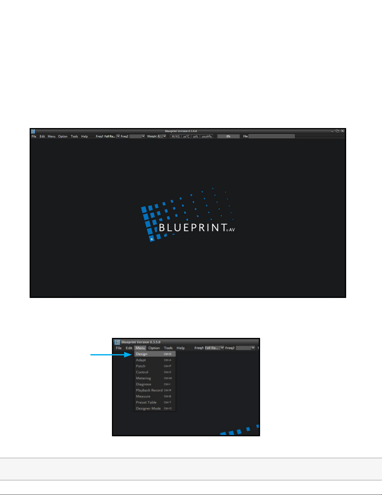
1. Launch Blueprint AV, bringing up the following base screen:
2. Select Design from the Menu drop-down, bringing up the default Design workspace
Adamson Systems Engineering | Blueprint Training Module
Page 4
Page 5
Section A:
Setting up basic 2D workspace
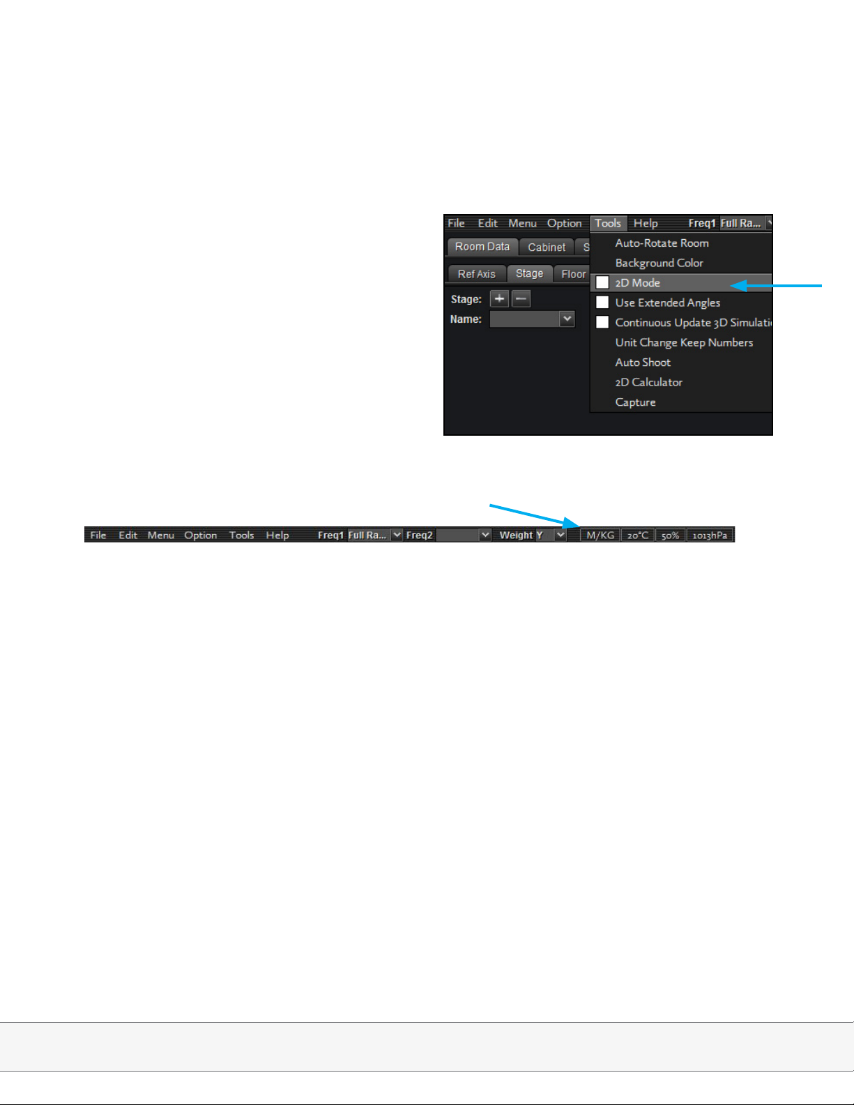
3. Select 2D Mode from the Tools menu
4. Dene Scale; Metric or Imperial
Adamson Systems Engineering | Blueprint Training Module
Page 5
Page 6
Section B:
Designing 2D Surfaces
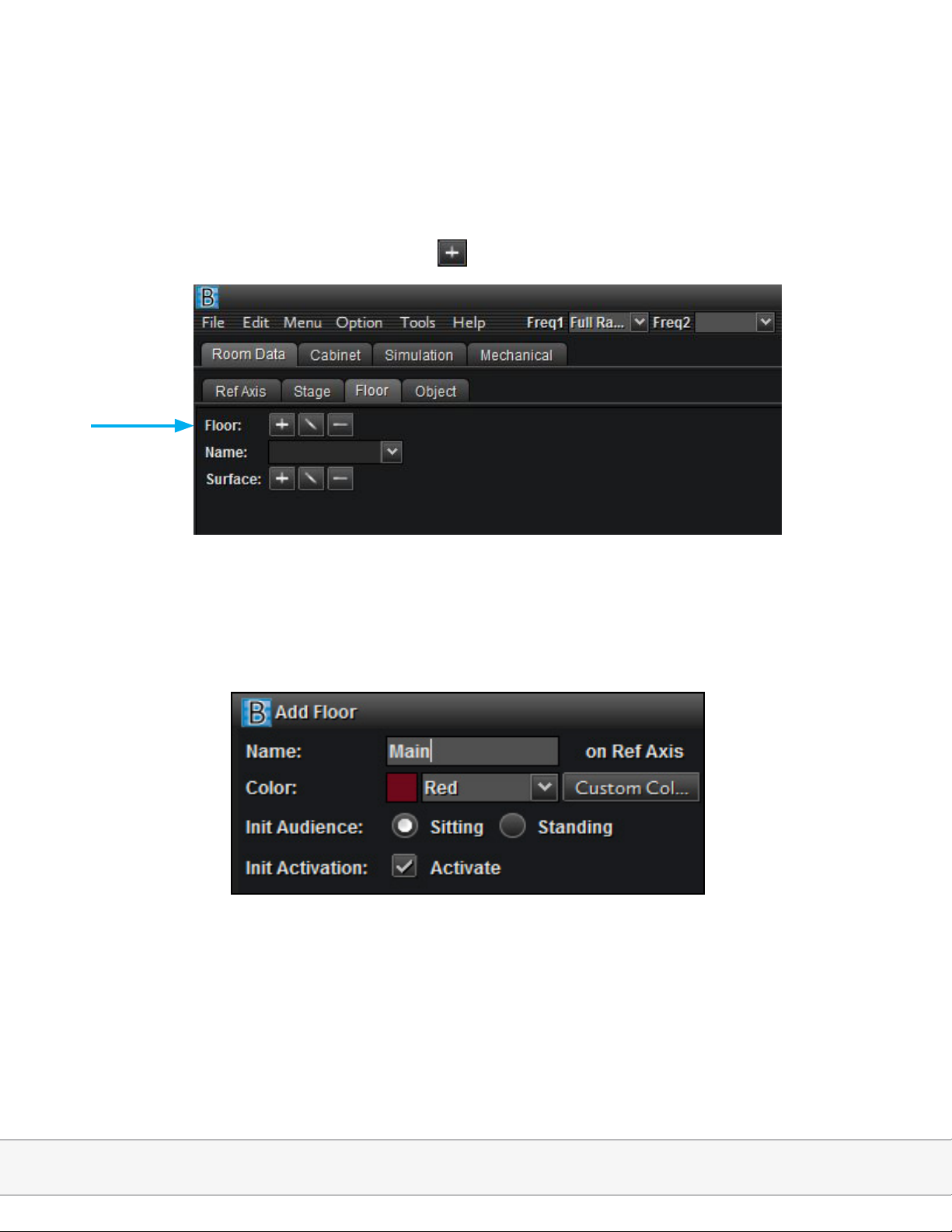
1. Room Data; Floor; Add Floor Group using button
2. Group Name, Color, Audience Listening Height, Activation (for simulation)
Adamson Systems Engineering | Blueprint Training Module
Page 6
Page 7
Section B:
Designing 2D Surfaces
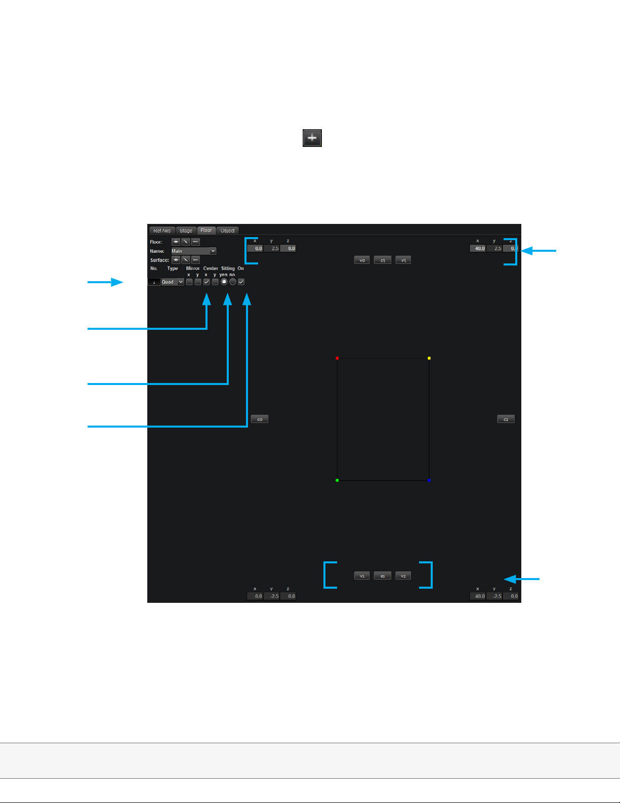
3. Create Surface in the Main Floor Group using button; X axis; Set the following coordinates
in the manual coordinate input elds.
Surface type
Mirror and
Center functions
Manual
coordinate
input
Audience
height
Activate
Surface
Note: -Center option duplicates data on alternate side of specied axis
-When using 2D mode the center button should always be checked.
Edge and
Vertex linking
feature
Adamson Systems Engineering | Blueprint Training Module
Page 7
Page 8
Section B:
Designing 2D Surfaces
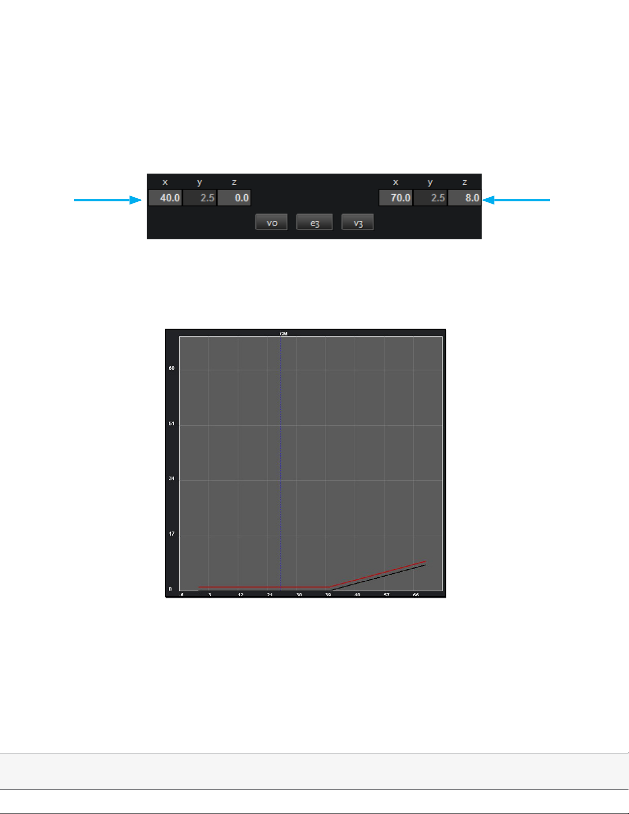
5. Create a second surface; Copy X axis data from surface 1, V3 and copy to X axis, V0; set X
and Z for V3 to the following coordinates in the manual coordinate input elds:
6. Cross Section of 2D surface
Height
Distance
Adamson Systems Engineering | Blueprint Training Module
Page 8
Page 9
Section C:
Cabinet Selection
Blueprint AV can help determine the optimum amount and type of boxes to hang in order to
achieve a desired SPL level in a given space.
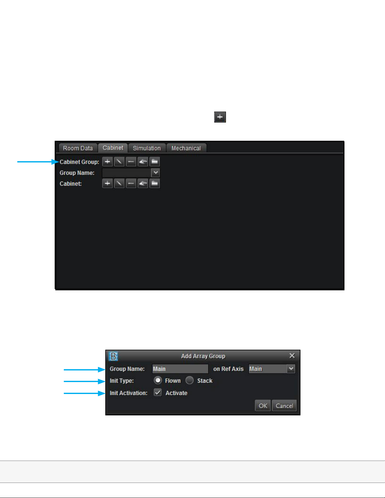
1. Cabinet; Create a new Cabinet Group by clicking the button.
2. A) Label the Cabinet Group under Group Name,
B) Choose to fly your Cabinet Group.
C) Activate your array.
A)
B)
C)
Adamson Systems Engineering | Blueprint Training Module
Page 9
Page 10
Section C:
Cabinet Selection
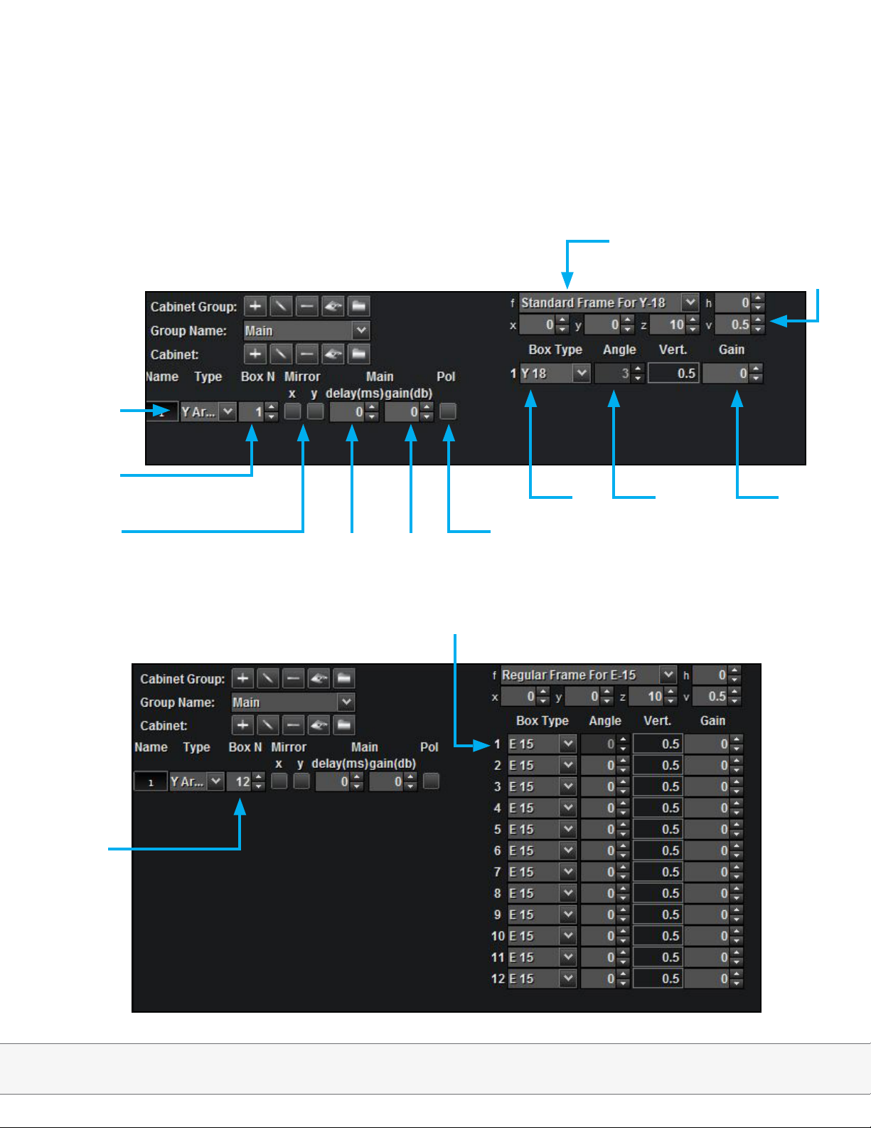
3. Cabinet Main Page
Loudspeaker
type
Rigging frame conguration
Rigging frame coordinates
Box N
(Amount of Boxes)
Mirror function
4. Change Box Type to E15, Box N to 12
12
Cabinet
delay
Cabinet
gain
E15
Polarity
flip
Box
type
Box Angle Box Gain
Adamson Systems Engineering | Blueprint Training Module
Page 10
Page 11

Section C:
Cabinet Selection
5. Select Auto Shoot function to determine base splay values
6. Select Z Frame and Only Angles
(selecting Box + Angles will alter your Box N)
Adamson Systems Engineering | Blueprint Training Module
Page 11
Page 12

Section C:
Cabinet Selection
7. Select Y weighting and change the Cross Section display to SPL.
SPL
Distance
Note: Y weighting (2K – 8K) is the best way to see perceived level variance within the listening area. The goal is to
maintain 6 dB corridor from front to back, which can be achieved by manipulating Box Angle and Gain.
Adamson Systems Engineering | Blueprint Training Module
Page 12
Page 13

Section C:
Cabinet Selection
8. Correct splay angles and gain to smooth
response
Note: The E15 is typically amplied in sets of 3. If gain trim is
anticipated for the lower boxes, you may prefer to congure
them in sets of 2
9. Corrected SPL graph
SPL
Distance
Adamson Systems Engineering | Blueprint Training Module
Page 13
Page 14

Section C:
Cabinet Selection
10. Dual frequency display is available on the toolbar
Note: It is advisable to check several individual frequencies to compare response
11. Dual SPL display example: 8000 (red) and 6300 (black)
SPL
Distance
Adamson Systems Engineering | Blueprint Training Module
Page 14
Page 15

Section D:
Mechanical View
1. Mechanical Page
a) Dimensions (Angles, Coordinates etc..)
b) Overall (Array Length)
c) Gravity (Weight distribution)
d) UHLoad (Underhang Load)
e) Name (Box Type label on / off)
f) Small Alarm Only (When rigging frame
doesn’t support array angle, changes
large alarm to small alarm)
g) Frame (Display rigging frame options)
h) Hanging Type (Display motor options)
i) Dimension list
Array length
Cabinet angles
Adamson Systems Engineering | Blueprint Training Module
Page 15
Page 16

Section E:
3D Mode Surface Design
1. Uncheck 2D Mode from the Tools menu to activate 3D mode; Press 3/4 view button; disable ref axis; Change all Y-axis data on both surfaces to 30
2. Create third surface; click the e0 button
Adamson Systems Engineering | Blueprint Training Module
Page 16
Page 17

Section E:
3D Mode Surface Design
3. Click back edge of inclined surface to link edge
4. Un-click e0, click Center, X axis on surface 3 and input the following data:
v0: X: 70.0, Y: 30.0, Z: 8.0; v3: X: 85.0, Y: 30.0, Z: 8.0
Adamson Systems Engineering | Blueprint Training Module
Page 17
Page 18

Section E:
3D Mode Surface Design
5. Create a new surface, select the Tri type
6. Click the e0 button, click right edge of rst surface
Adamson Systems Engineering | Blueprint Training Module
Page 18
Page 19

Section E:
3D Mode Surface Design
7. Un-click e0, input the following data: v2: X: 40.0, Y: -40.0, Z:0.0
8. Create new surface, link e3 to right edge of incline surface, e0 to back of Tri surface
and input the following data for v2: X: 70.0, Y: -40.0, Z:8.0
Adamson Systems Engineering | Blueprint Training Module
Page 19
Page 20

Section E:
3D Mode Surface Design
9. Create new surface, link e3 to right edge of back surface, e0 to back edge of incline surface and input the following data for v2: X: 85.0, Y: -40.0, Z: 8.0
10. Select Mirror X for surfaces 4, 5 and 6:
Adamson Systems Engineering | Blueprint Training Module
Page 20
Page 21

Section F:
3D Mode Complex Surface Design
In this section we utilize the more advanced Extrude and Revolve surfaces, as well as the
2D calculator tool, to build a complex space.
⦁
1. File; New Design
2. Room Data; Stage; Button to create a new stage; input the following values
Note: As the stage is created centered on-axis, there is no need to determine Front or Angle coordinates
3. Room Data; Floor; Button to create new Floor; label the floor “Main”; create Quad
surface
Adamson Systems Engineering | Blueprint Training Module
Page 21
Page 22

Section F:
3D Mode Complex Surface Design
4. Open the 2D Calculator either from the Tools menu, or by right clicking on an X, Y, or Z
coordinate; Input the following data; set the results to v2 and v3
Note: From refers to the point of measurement. Using a distance and incline meter would result in the Polar
values in this space.
5. Manually enter the following Y axis data to set the width of the Quad surface:
Adamson Systems Engineering | Blueprint Training Module
Page 22
Page 23

Section F:
3D Mode Complex Surface Design
5. Create a new surface; select the Extrude surface type
List of Extrude functionalities
⦁ A) No. of Points (Amount of points in given Extrude)
⦁ B) Dir. (Extrude will center on X axis in the direction specied)
⦁ C) Explode (Extrude will separate at each point into individual surfaces)
⦁ D) Dimension (Width of Extrude)
⦁ E) Link buttons (To link Extrude with Revolve surface)
Adamson Systems Engineering | Blueprint Training Module
Page 23
Page 24

Section F:
3D Mode Complex Surface Design
6. Extrude; change # of Points to 4; change Dimension to 20; change Direction to <..>
⦁7. Open 2D calculator and input the fol-
lowing data:
⦁ A) Distance 55.0, Angle 4.7°; set to
Point 2
⦁ B) Distance 62.0, Angle 4.16°; set
to Point 3
⦁ Distance 90.0, Angle 8°; set to
Point 4
Adamson Systems Engineering | Blueprint Training Module
Page 24
Page 25

Section F:
3D Mode Complex Surface Design
8. Manually enter 40.0 for X and 0.0 for Z of Point 1 to match Extrude to Quad; resulting
surface:
9. Create a new surface; select the Revolve surface type
List of Revolve functionalities
a) Type (Angle or Chords)
b) # Points (Amount of separate surfaces
within revolve)
c) Dir (Direction surface extends from the
X Axis)
d) Angle (Angle of revolve)
e) # Sectors (Amount of individual sectors
comprising revolve surface)
f) Explode (Convert sectors to individual
surfaces)
g) Lock (Radius Lock)
h) Center (X,Y,Z position of revolve center)
i) R (Radius)
j) Link L & R (Linking function for
Extrude)
Adamson Systems Engineering | Blueprint Training Module
Page 25
Page 26

Section F:
3D Mode Complex Surface Design
10. Click the Link R button; click the left side of the Extrude to link the right side of the
Revolve to the Extrude surface
11. Type; change Angle to Chord; change front chord value to 0.0
Adamson Systems Engineering | Blueprint Training Module
Page 26
Page 27

Section F:
3D Mode Complex Surface Design
12. Type; change Chord to Angle; change angle value to 90°
13. Create a new surface; select the Extrude surface type; change dimension to 20; click the
Link R button; select the un-linked edge of the Revolve; change direction to <-->
Adamson Systems Engineering | Blueprint Training Module
Page 27
Page 28

Section F:
3D Mode Complex Surface Design
14. Mirror surfaces across appropriate axis to create full Arena
Adamson Systems Engineering | Blueprint Training Module
Page 28
Page 29

Section G:
Complex Cabinet Placement and Simulation
1. Cabinet; create new Cabinet Group by pressing ; label Main
2. Add Cabinet by pressing ; change Box Type to E15; change Box N to 15; change bot-
tom 3 cabinets to E12
Adamson Systems Engineering | Blueprint Training Module
Page 29
Page 30

Section G:
Complex Cabinet Placement and Simulation
3. Click Auto Shoot button; select Z Frame; select Near Field Limit until frame + 5 m; select
Only Angles; change bottom 2D graph to SPL
4. Change weighting to Y; correct splay values to smooth response; set Y axis of Cabinet to
13; mirror Cabinet on X axis
Adamson Systems Engineering | Blueprint Training Module
Page 30
Page 31

Section G:
Complex Cabinet Placement and Simulation
5. Simulation; SPL; click Draw 3D button; compare with Scale by hovering over >>
6. Cabinet; add Cabinet by clicking the + button; change Box Type to E12; Change Box N to
9; set Y axis of cabinet to 16; change h to 45; click Auto Shoot button; select Z Frame and
Only Angles
Adamson Systems Engineering | Blueprint Training Module
Page 31
Page 32

Section G:
Complex Cabinet Placement and Simulation
7. Correct splay values to smooth response; mirror Cabinet on X axis
8. Simulation; SPL; click Draw 3D button; compare with Scale by hovering over >>
Adamson Systems Engineering | Blueprint Training Module
Page 32
Page 33

Section G:
Complex Cabinet Placement and Simulation
9. Change weighting to A; click Draw 3D button; compare with Scale by hovering over >>
Adamson Systems Engineering | Blueprint Training Module
Page 33
 Loading...