

Page 1
Operating manual
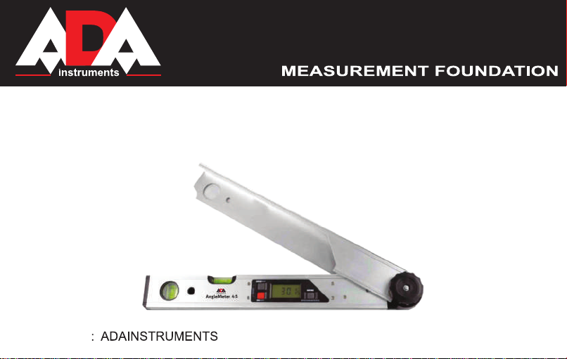
Digital Angle Finder
Model: AngleMeter 45
Manufacturer
Address: WWW. ADAINSTRUMENTS.COM
Page 2

2
Table of contents
1. Display . . . . . . . . . . . . . . . . . . . . . . . . . . . . . . . . . . . . . . . . . . . . . . . . . . . . . . . . . . . . . 3
2. Appearance . . . . . . . . . . . . . . . . . . . . . . . . . . . . . . . . . . . . . . . . . . . . . . . . . . . . . . . . . . . 4
3. Installing batteries . . . . . . . . . . . . . . . . . . . . . . . . . . . . . . . . . . . . . . . . . . . . . . . . . . . . . . 4
4. Operating instructions . . . . . . . . . . . . . . . . . . . . . . . . . . . . . . . . . . . . . . . . . . . . . . . . . . . . . . 5
5. Technical data . . . . . . . . . . . . . . . . . . . . . . . . . . . . . . . . . . . . . . . . . . . . . . 9
6. Warranty/Exceptions from responsibility . . . . . . . . . . . . . . . . . . . . . . . . . . . . . . . . . . . . . . . . . . . . . . 10
Appendix 1. Warranty card
Appendix 2. Certificate of acceptance and sale
AngleMeter 45
Page 3
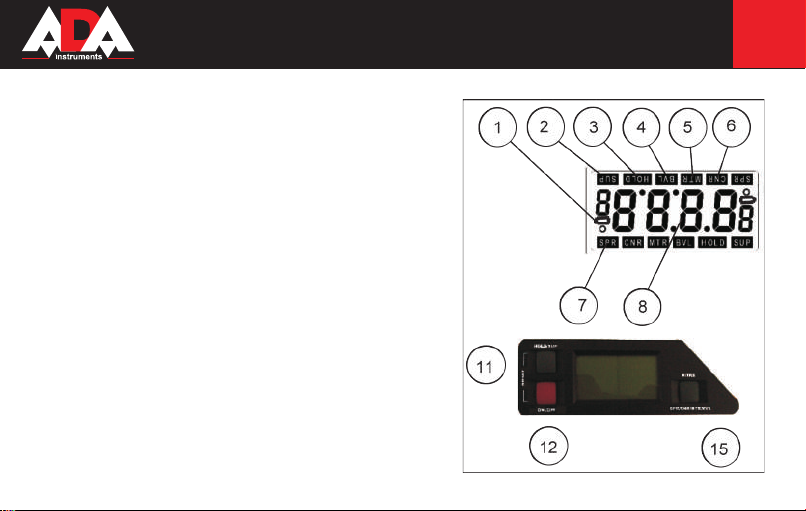
DISPLAY
1. Battery life icon
2. SUP indicator
3. HOLD indicator
4. BVL indicator
5. MTR indicator
6. CNR indicator
7. SPR indicator
8. Angle display
AngleMeter 45
3
pic. 1
Page 4
4
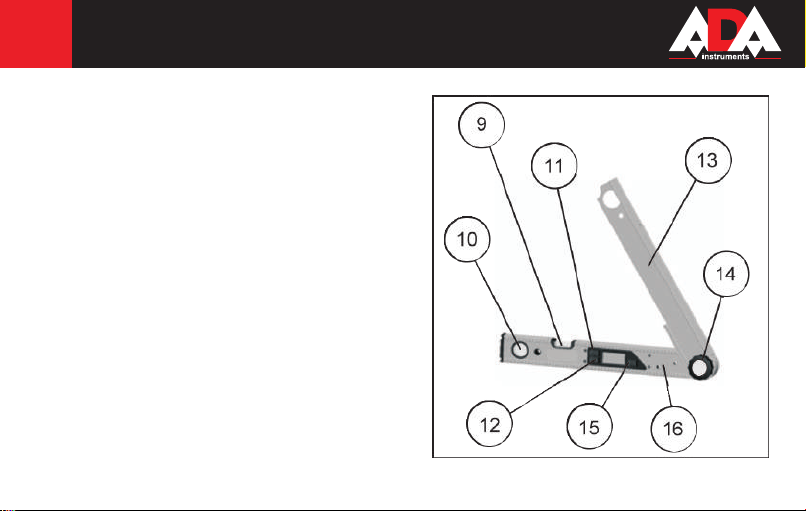
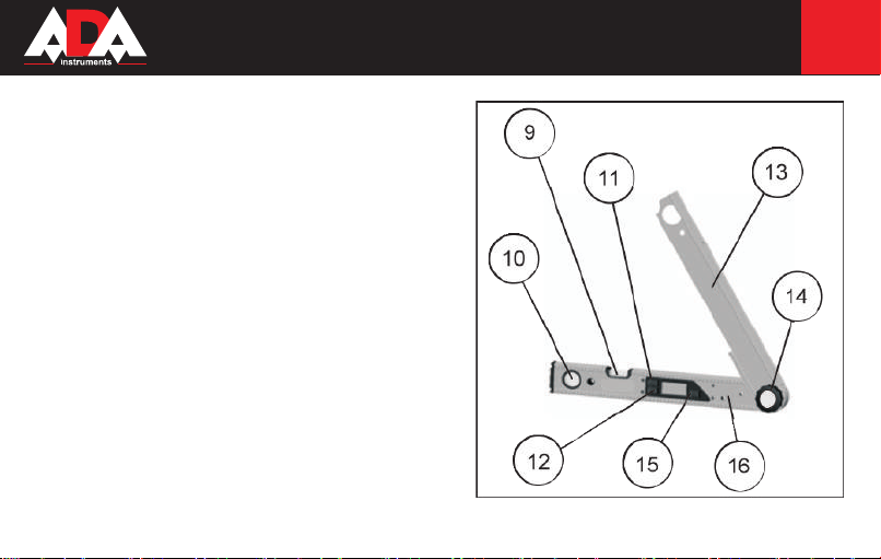
APPEARANCE
9. Level vial
10. Plumb vial
11. HOLD/SUP button
12. ON/OFF button
13. Adjustable arm
14. Tension knob
15. MITRE button
16. Level arm
INSTALLING BATTERIES
1) Lift arm to expose battery compartment which is located
on the back of the product
2) Remove cover
3) Insert 2xAAA batteries
4) Replace cover and snap in place
AngleMeter 45
pic. 2
Page 5

AngleMeter 45
OPERATING INSTRUCTIONS
Power
Press the ON/OFF button (12) for ~1 sec to turn on the display and backlight.
The angle (8) which represents the angle between the arms (13 and 16) will be displayed in degrees (°).
The display will automatically power off after ~5 min of non-use.
The backlight will automatically power off after ~1 min of non-use. Any button press or angle change will cause the backlight to
power on if the display is powered on.
The battery life icon (1) will appear when there is ~2 hours of battery life remaining.
Press the ON/OFF button (12) for ~2 sec to power off the display.
Invert Display
With the display powered on, press the ON/OFF button (12) for ~1 sec to invert the display. Press again for ~1 sec to return display
to normal position.
Re-calibrate
If the unit is dropped or you suspect inaccuracy of the product, you can re-calibrate the zero point. With the power on and the arms (13
and 16) closed together, press the ON/OFF (12) and HOLD/SUP (11) buttons simultaneously for ~1 sec to reset the angle to 0°.
Hold
Press the HOLD/SUP button (11) for ~1 sec to lock the current angle shown on the display. The HOLD indicator (3) will appear
and flash on the display. Press (11) again for ~1 sec to unlock the displayed angle.
5
Page 6

6
Supplemental angle
Press the HOLD/SUP button (11) for ~2 seс to change the display to the
supplemental angle.The supplemental angle is 180° minus the current angle
between the arms (13 and 16). The SUP indicator (2) will appear and flash
on the display. Press (11) again for ~2 sec to return to normal angle.
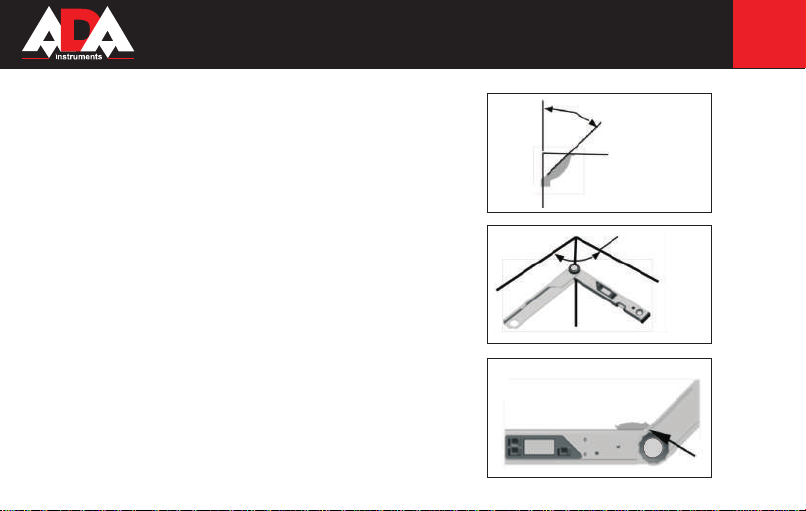
Easy Mitre Angle
With the arms (13 and 16) set to the desired angle, press the MITRE button
(15) for ~1 sec. The mitre angle (90° - ½X) will be shown. The display will
be locked on that angle and the MITRE indicator (5) will appear and flash
on the display. To set the mitre saw, see pic.3, setting M.
Compound Angle Mode
For compound angles such as cuts for crown molding, you will need to enter
compound mitre mode and store two angles into memory; the Spring (SPR)
and Corner (CNR) angles (see pic. 4 and 5). The unit will then calculate the
Mitre and Bevel angles needed to set a compound mitre saw. See pic. 3, settings M (mitre) and B (bevel).
Note: If you do not know the spring angle of the item you are working with,
it is easier to get that angle before starting. The spring (SPR) angle is usually
38° or 45° for crown molding. See pic. 4.
AngleMeter 45
pic. 3
Page 7
This is done by placing the molding as shown in pic. 6. Once the arms are set
to matching the angle of the item, press the HOLD/SUP button (11) for ~2
sec to get the supplemental angle. That will be the spring (SPR) angle.
EX: Angle between arms = 135°
Supplemental angle = 45°
Step 1: Start compound mitre mode. Press the MITRE button (15) for ~2
sec. The SPR indicator (7) will flash and the SPR angle that was last stored
into memory will be shown for ~2 sec.
Step 2: The SPR indicator (7) will stop flashing and the display will again
show the active angle. If the stored SPR angle needs to be changed, adjust
the arms (13 and 16) until the displayed angle matches the known spring
angle (typ. 38° or 45°). Then press the MITRE button (15) for ~2 sec. The
displayed angle and SPR will flash once and the spring (SPR) angle is now
stored in memory.
If the stored spring angle does not need to be changed, press MITRE button
(15) for ~1 sec to move to the next step.
Step 3: If you do not already have the CNR indicator (6) shown in the display, press the MITRE button (15) for ~1 sec. The CNR indicator will flash
and the CNR angle that was last stored (6) into memory will be shown for ~2
sec. The CNR indicator (6) will stop flashing and the display will again show
the active angle. If the stored CNR angle needs to be changed, adjust the
arms (13 and 16) as shown in pic. 5. To store the corner angle into memory,
AngleMeter 45
7
pic. 4
pic. 5
pic. 6
Page 8

8
press the MITRE button (15) for ~2 sec. The displayed angle and the CNR indicator (6) will flash once and the corner (CNR) angle is
now stored in memory.
If the stored corner angle does not need to be changed, press MITRE button (15) for ~1 sec to move to the next step.
Step 4: If you do not already have the MTR indicator (5) shown in the display, press the MITRE button (15) for ~1 sec. This is the
calculated mitre angle for setting the saw. See pic. 3, angle M.
Step 5: Press the MITRE button (15) for ~1 sec to change the display to the bevel angle. The BVL indicator (4) will be displayed. This
is the bevel angle for setting the saw. See pic. 3, Angle B.
Press the MITRE button (15) for ~1 sec to cycle back through the stored spring angle, the stored corner angle and the calculated mitre
and bevel angles.
Press the ON/OFF button (12) at any time for ~1 sec to exit compound angle mode.
AngleMeter 45
Page 9

TECHNICAL DATA
Power 3VDC 2xAAA Batteries (included)
Measuring range 0-225°
Digital angle accuracy ±0.1°
Vial(s) accuracy 0.057 ° (1 mm/m)
Operating temperature -10°C to 50°C
Storage temperature -20° to 70°C
Battery life ~100 Hrs
Shock resistance up to 1 m drop on concrete
Water resistance water resistant, but not waterproof
AngleMeter 45
9
Page 10

10
Warranty
This product is warranted by the manufacturer to the original purchaser to be free from defects in material and workmanship under
normal use for a period of two (2) years from the date of purchase.
During the warranty period, and upon proof of purchase, the product will be repaired or replaced (with the same or similar model at
manufactures option), without charge for either parts of labour.
In case of a defect please contact the dealer where you originally purchased this product. The warranty will not apply to this product
if it has been misused, abused or altered. Withiut limiting the foregoing, leakage of the battery, bending or dropping the unit are
presumed to be defects resulting from misuse or abuse.
Exceptions from responsibility
The user of this product is expected to follow the instructions given in operators’ manual.
Although all instruments left our warehouse in perfect condition and adjustment the user is expected to carry out periodic checks of
the product’s accuracy and general performance.
The manufacturer, or its representatives, assumes no responsibility of results of a faulty or intentional usage or misuse including any
direct, indirect, consequential damage, and loss of profits.
The manufacturer, or its representatives, assumes no responsibility for consequential damage, and loss of profits by any disaster
(earthquake, storm, flood ...), fire, accident, or an act of a third party and/or a usage in other than usual conditions.
The manufacturer, or its representatives, assumes no responsibility for any damage, and loss of profits due to a change of data, loss
of data and interruption of business etc., caused by using the product or an unusable product.
The manufacturer, or its representatives, assumes no responsibility for any damage, and loss of profits caused by usage other thsn
explained in the users’ manual.
The manufacturer, or its representatives, assumes no responsibility for damage caused by wrong movement or action due to connecting with other products.
AngleMeter 45
Page 11

WARRANTY DOESN’T EXTEND TO FOLLOWING CASES:
1. If the standard or serial product number will be changed, erased, removed or wil be unreadable.
2. Periodic maintenance, repair or changing parts as a result of their normal runout.
3. All adaptations and modifications with the purpose of improvement and expansion of normal sphere of product application, mentioned in the service instruction, without tentative written agreement of the expert provider.
4. Service by anyone other than an authorized service center.
5. Damage to products or parts caused by misuse, including, without limitation, misapplication or nrgligence of the terms of service
instruction.
6. Power supply units, chargers, accessories, wearing parts.
7. Products, damaged from mishandling, faulty adjustment, maintenance with low-quality and non-standard materials, presence of
any liquids and foreign objects inside the product.
8. Acts of God and/or actions of third persons.
9. In case of unwarranted repair till the end of warranty period because of damages during the operation of the product, it’s transportation and storing, warranty doesn’t resume.
For more information you can visit our website WWW.ADAINSTRUMENTS.COM
or write the letter with your questions on info@adainstruments.com
Page 12

WARRANTY CARD
Name and model of the product ________________________________________________
Serial number ________________date of sale_______________________
Name of commercial organization _____________________stamp of commercial organization
Warranty period for the instrument explotation is 24 months after the date of original retail purchase.
During this warranty period the owner of the product has the right for free repair of his instrument in case of manufacturing defects.
Warranty is valid only with original warranty card, fully and clear filled (stamp or mark of thr seller is obligatory).
Technical examination of instruments for fault identification which is under the warranty, is made only in the authorized service center.
In no event shall manufacturer be liable before the client for direct or consewuential damages, loss of profit or any other damage which
occur in the result of the instrument outage.
The product is received in the state of operability, without any visible damages, in full completeness. It is tested in my presence. I have no
complaints to the product quality. I am familiar with the conditions of qarranty service and i agree.
purchaser signature _______________________________
Before operating you should read service instruction!
If you have any questions about the warranty service and technical support contact seller of this product
Page 13

Certificate of acceptance and sale
__________________________________________________________________________
__________________________________________________________________________
___________________________________________________________№_____________
name and model of the instrument
Corresponds to ______________________________________________________________
designation of standard and technical requirements
Data of issue _______________________________________________________________
Stamp of quality control department
Price
Sold ___________________________________ Date of sale ______________________
name of commercial establishment
Page 14

Руководство по эксплуатации
Цифровой угломер
Модель: AngleMeter 45
Производитель: ADAINSTRUMENTS Адрес: WWW.ADAINSTRUMENTS.COM
Page 15

AngleMeter 45
Содержание
1. Внешний вид . . . . . . . . . . . . . . . . . . . . . . . . . . . . . . . . . . . . . . . . . . . . . . . . . . . . . . . . . . . . . 14
2. Значки на дисплее . . . . . . . . . . . . . . . . . . . . . . . . . . . . . . . . . . . . . . . . . . . . . . . . . . . . . . . . . . . 15
3. Кнопки/функции . . . . . . . . . . . . . . . . . . . . . . . . . . . . . . . . . . . . . . . . . . . . . . . . . . . . . . 15
4. Калибровка . . . . . . . . . . . . . . . . . . . . . . . . . . . . . . . . . . . . . . . . . . . . . . . . . . . . . . 16
5. Технические характеристики . . . . . . . . . . . . . . . . . . . . . . . . . . . . . . . . . . . . . . . . . . . . . . 18
6. Гарантия/Освобождение от ответственности . . . . . . . . . . . . . . . . . . . . . . . . . . . . . . . . . . . . . . . . . . . . . . 19
Приложение 1. Гарантийный талон
Приложение 2. Свидетельство о приемке и продаже
15
Page 16

16
ДИСПЛЕЙ
1. Индикатор батареи
2. SUP (режим измерения дополнительного угла)
3. HOLD (сохранение значения измеренного угла)
4. BVL (отображение вертикального угла распила)
5. MTR (отображение горизонтального угла распила)
6. CNR (отображение внутреннего угла основания)
7. SPR (отображение угла наклона)
8. Отображение угла
AngleMeter 45
рис. 1
Page 17
ВНЕШНИЙ ВИД
9. Горизонтальный пузырьковый уровень
10. Вертикальный пузырьковый уровень
11. Клавиша сохранения значения измеренного угла
HOLD/режим измерения дополнительного угла SUP
12. Клавиша включения/выключения ON/OFF
13. Регулируемое плечо лазерного уровня
14. Зажимной винт
15. Клавиша режима измерения одностороннего скоса
16. Горизонтальное плечо
УСТАНОВКА БАТАРЕЙ
1) Поднимите плечо инструмента. Батарейный отсек
расположен на обратной стороне прибора
2) Снимите крышку батарейного отсека
3) Вставьте 2xAAAбатареи
4) Закройте крышку батарейного отсека
AngleMeter 45
17
рис. 2
Page 18

18
РАБОТА С ИНСТРУМЕНТОМ
Вкл/выкл
Нажмите кнопку ON/OFF (12), чтобы вкдючить инструмент и подсветку. При включении уровня на дисплее автоматически
отображается угол в градусах между плечами (13) и (16).
Прибор автоматически отключается, если вы им не пользуетесь более 5 мин.
Подсветка выключается автоматически, если вы не пользуетесь инструментом более 1 мин.
Индикатор заряда батареи (1) появится на дисплее, когда останется 2 часа до полного разряда батареи.
Нажмите и удерживайте кнопку ON/OFF в течение 2 сек, чтобы выключить прибор.
Перевернутые показания на дисплее
Включите прибор, быстро нажмите на кнопку ON/OFF (12) - показания на дисплее отобразятся
в перевернутом виде. Нажмите коротко кнопку ON/OFF, чтобы вернуться к стандартному отображению на дисплее.
Калибровка
Если вы уронили прибор или прибор выдает неточные результаты измерения, переустановите точку нуля.
Калибровку прибора можно произвести в любое время. Поместите прибор на ровную поверхность в сложенном виде
и включите его. Нажмите на кнопки ON/OFF (12) и HOLD/SUP (11) одновременно и удерживайте их в течение 2-х сек,
чтобы откалибровать точку нуля.
Сохранение измеренного значения (HOLD)
Нажмите на кнопку HOLD/SUP (11), чтобы активировать функцию сохранения измеренного значения угла (HOLD). Текущее значение
будет зафиксировано и на дисплее отобразится символ HOLD (3). Нажмите снова кнопку HOLD/SUP (11), чтобы выйти из функции.
AngleMeter 45
Page 19

Дополнительный (приложенный) угол
Нажмите и удерживайте кнопку HOLD/SUP (11) в течение 2 сек, чтобы
активизировать функцию дополнительного угла. Дополнительный угол (180° минус
значение текущего угла между плечами (13) и (16)) отображается на дисплее и вы
так же можете увидеть символ “SUP”(2). Чтобы вернуться в стандартный режим
измерения, нажмите и удерживайте кнопку HOLD/SUP (11) в течение 2х сек.
Горизонтальный угол распила (режим «одностороннего скоса»)
Режим «одностороннего скоса» служит для расчета угла распила «MTR», когда 2
заготовки с одинаковым углом скоса должны образовывать ровный стык (например
плинтуса в углу комнаты). Это угол можно выставить на шкале торцовочной пилы или
установке для распиловки.
Измерьте угол (=х) и нажмите на кнопку “MITRE” (15). На дисплее отобразится угол
(90° - 0.5х) и значок “MITRE”(5).
Режим «двустороннего скоса»
Режим «двустороннего скоса» служит для расчета горизонтальных и вертикальных углов
распила (например, в случае потолочных плинтусов). Войдите в режим двустороннего
скоса и сохраните в памяти 2 значения угла: Наклон (SPR) и угол (CNR).
Важно: Если вы не знаете угол наклона, измерьте его перед тем, как начать работу в
режиме “двустороннего скоса” (выполните действия согласно раздела «Дополнительный
угол»). Угол наклона совпадает с дополнительным углом. Угол наклона (SPR) обычно
составляет 38° или 45° в случае потолочных плинтусов (см. рис. 4).
AngleMeter 45
pic. 3
19
Page 20

20
Две заготовки с различными углами должны с предельной точностью
состыковываться друг с другом (рис. 6). Нажмите кнопку HOLD/SUP
(11) и удерживайте ее более 1 сек, чтобы получить дополнительный
угол. Это и будет угол наклона.
Например: Угол между плечами = 135 градусов
Дополнительный угол = 45 градусов.
Шаг 1: Нажмите на кнопку “MITRE” (15) (более 2 сек), чтобы начать
работу в режиме двустороннего скоса. Индикация SPR (7) начнет
мигать и на дисплее отобразится последний сохраненный угол наклона
SPR. Через 2 сек мигание прекратиться и на дисплее отобразится
значение активного угла.
Шаг 2: Если сохраненное значение угла наклона необходимо изменить,
задайте плечам угломера ((13) и (16)) необходимый угол. Затем нажмите
на кнопку “MITRE” (15), чтобы сохранить новый угол. Индикация угла
наклона SPR и значение сохраненного угла будут мигать, указывая на то,
что новый угол сохранен в памяти в качестве угла наклона (SPR).
Если сохраненное значение угла наклона нет необходимости менять,
нажмите на кнопку “MITRE” (15),чтобы приступить к следующему шагу.
Шаг 3: Если индикация внутреннего угла основания (например между
стенами) CNR (6) еще не отобразилась на дисплее, нажмите на кнопку
“MITRE” (15). Индикация внутреннего угла основания CNR начнет
мигать и на дисплее отобразится последний сохраненный внутренний
AngleMeter 45
pic. 4
pic. 5
pic. 6
Page 21

AngleMeter 45
угол основания CNR (6). Через 2 сек мигание прекратится и на дисплее отобразится активный угол. Если сохраненное
значение угла CNR необходимо изменить, установите плечи уровня ((13) и (16)) как показано на рисунке G. Чтобы сохранить
угол, нажмите кнопку MITTRE (15) и удерживайте ее более 2х сек. Отображаемое значение угла и индикатор CNR (6) начнут
мигать и значение угла CNR сохранится в памяти прибора.
Если значение угла нет необходимости менять, нажмите на кнопку “MITRE” (15), чтобы перейти к следующему шагу.
Шаг 4: Если индикация MTR (5) еще не отобразилась на дисплее, нажмите на кнопку “MITRE” (15). На дисплее отображается
рассчитанный горизонтальный угол распила (рис. 3, угол М).
Шаг 5: Нажмите еще раз на кнопку “MITRE” (15). На дисплея отображается индикация вертикального угла распила BVL (4).
На дисплее отображается рассчитанный вертикальный угол распила для торцовочной пилы. (Рис. 3, угол В)
При необходимости можно вновь вызвать на дисплей результаты расчетов. Нажмите кнопку “MITRE“ (15), чтобы просмотреть
сохраненные значения угла наклона, углового угла и рассчитанные горизонтальный и вертикальный углы распила.
Нажмите на кнопку ON/OFF (12), чтобы выйти из режима двустороннего скоса.
21
Page 22

22
TECHNICAL DATA
Источник питания 3VDC 2xAAA батареи
Диапазон измерения 0-225°
Точность измерения угла ±0.1°
Точность пузырьковых уровней 0.057 ° (1 мм/м)
Рабочая температура -10°C .. 50°C
Температура хранения -20° .. 70°C
Срок службы батарей ~100 часов
Ударопрочность падение на бетон с высоты до 1 м
Водостойкость водостойкий, но не водонепроницаемый
AngleMeter 45
Page 23

AngleMeter 45
Гарантия
Производитель предоставляет гарантию на продукцию покупателю в случае дефектов материала или качества его
изготовления во время использования оборудования с соблюдением инструкции пользователя на срок до 2 лет со дня покупки.
Во время гарантийного срока, при предъявлении доказательства покупки, прибор будет починен или заменен на такую же или
аналогичную модель бесплатно. Гарантийные обязательства также распространяются и на запасные части.
В случае дефекта, пожалуйста, свяжитесь с дилером, у которого вы приобрели прибор. Гарантия не распространяется
на продукт, если повреждения возникли в результате деформации, неправильного использования или ненадлежащего
обращения.
Все вышеизложенные безо всяких ограничений причины, а также утечка батареи, деформация прибора являются дефектами,
которые возникли в результате неправильного использования или плохого обращения.
Освобождение от ответственности
Пользователю данного продукта необходимо следовать инструкциям, которые приведены в руководстве по эксплуатации.
Даже, несмотря на то, что все прборы проверены производителем, пользователь должен проверять точность прибора и его
работу.
Производитель или его представители не несут ответственности за прямые или косвенные убытки, упущенную выгоду или
иной ущерб, возникший в результате неправильного обращения с прибором.
Производитель или его представители не несут ответственности за косвенные убытки, упущенную выгоду, возникшие в
результате катастроф (землетрясение, шторм, наводнение и т.д.), пожара, несчастных случаев, действия третьих лиц и/или
использование прибора в необычных условиях.
Производитель или его представители не несут ответственности за косвенные убытки, упущенную выгоду, возникшие в
результате изменения данных, потери данных и временной приостановки бизнеса и т.д., вызванных применением прибора.
Производитель или его представители не несут ответственности за косвенные убытки, упущенную выгоду, возникшие в
результате использования прибора не по инструкции.
23
Page 24

ГАРАНТИЙНЫЕ ОБЯЗАТЕЛЬСТВА НЕ РАСПРОСТРАНЯЮТСЯ НА СЛЕДУЮЩИЕ СЛУЧАИ:
1.Если будет изменен, стерт, удален или будет неразборчив типовой или серийный номер на изделии;
2.Периодическое обслуживание и ремонт или замену запчастей в связи с их нормальным износом;
3.Любые адаптации и изменения с целью усовершенствования и расширения обычной сферы применения изделия,
указанной в инструкции по эксплуатации, без предварительного письменного соглашения специалиста поставщика;
4.Ремонт, произведенный не уполномоченным на то сервисным центром;
5.Ущерб в результате неправильной эксплуатации, включая, но не ограничиваясь этим, следующее: использовнаие изделия
не по назначению или не в соответствии с инструкцией по эксплуатации на прибор;
6.На элементы питания, зарядные устройства, комплектующие, быстроизнашивающиеся и запасные части;
7. Изделия, поврежденные в результате небрежного отношения, неправильной регулировки, ненадлежащего технического
обслуживания с применением некачественных и нестандартных расходных материалов, попадания жидкостей и
посторонних предметов внутрь.
8.Воздействие факторов непреодолимой силы и/или действие третьих лиц;
9.В случае негарантийного ремонта прибора до окончания гарантийного срока, произошедшего по причине полученных
повреждений в ходе эксплуатации, транспортировки или хранения, и не возобновляется.
Для получения дополнительной информации Вы можете посетить наш Интернет сайт WWW.ADAINSTRUMENTS.COM
или написать письмо с интересующими Вас вопросами на электронный адрес info@adainstruments.com
Page 25

ГАРАНТИЙНЫЙ ТАЛОН
Наименование изделия и модель _______________________________________________
Серийный номер ___________________Дата продажи_________________
Наименование торговой организации ___________________Штамп торговой организации мп.
Гарантийный срок эксплуатации приборов составляет 24 месяца со дня продажи и распространяется на оборудование,
ввезенное на территорию РФ официальным импортером.
В течении гарантийного срока владелец имеет право на бесплатный ремонт изделия по неисправностям, являющимся
следствием производственных дефектов.
Гарантийные обязательства действительны только по предъявлении оригинального талона, заполненного полностью и четко
(наличие печати и штампа с наименованием и формой собственности продавца обязательно).
Техническое освидетельствование приборов (дефектация) на предмет установления гарантийного случая производится
только в авторизованной мастерской.
Производитель не несет ответственности перед клиентом за прямые или косвенные убытки, упущенную выгоду или иной
ущерб, возникшие в результате выхода из строя приобретенного оборудования.
Правовой основой настоящих гарантийных обязательств является действующее законодательство, в частности, Федеральный
закон РФ “О защите прав потребителя” и Гражданский кодекс РФ ч.II ст. 454-491.
Товар получен в исправном состоянии, без видимых повреждений, в полной комплектности, проверен в моем присутствии,
претензий по качеству товара не имею. С условиями гарантийного обслуживания ознакомлен и согласен.
Подпись получателя_________________________________
Перед началом эксплуатации внимательно ознакомьтесь с инструкцией по эксплуатации!
По вопросам гарантийного обслуживания и технической поддержки обращаться к продавцу данного товара
Page 26

СВИДЕТЕЛЬСТВО О ПРИЕМКЕ И ПРОДАЖЕ
______________________________________________________________________________________________
______________________________________________________________________________________________
_____________________________________________________________________________№_______________
НАИМЕНОВАНИЕ И ТИП ПРИБОРА
Соответствует __________________________________________________________________________________
обозначение стандарта и технических условий
Дата выпуска ___________________________________________________________________________________
Штамп ОТК (клеймо приемщика)
Цена
Продан(а) ___________________________________________________Дата продажи ______________________
Page 27

Page 28

ADA
MEASUREMENT FOUNDATION
WWW.ADAINSTRUMENTS.COM
 Loading...