

Page 1
Raspberry Pi Pico and LED Arcade Button MIDI Controller
Created by Ruiz Brothers
Last updated on 2021-04-15 10:02:00 AM EDT
Page 2

2
5
5
5
5
6
6
6
7
8
9
10
10
11
12
12
18
20
20
20
20
21
22
23
24
24
25
25
25
25
25
26
27
27
27
27
28
28
29
29
31
31
31
32
32
33
33
33
34
35
35
35
35
Guide Contents
Guide Contents
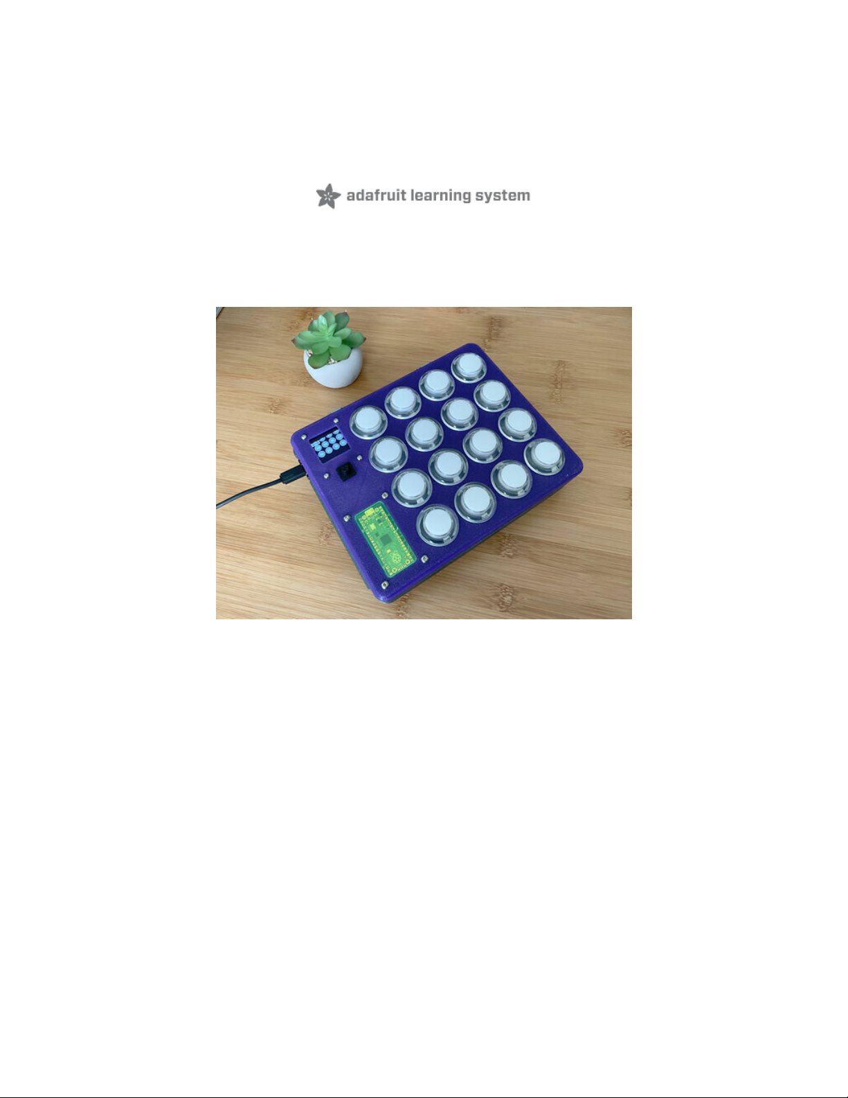
Overview
DIY MIDI Controller
Buttons and LEDs
Edit MIDI on the Fly
Intuitive UI/UX
Kickstand Handle
Prerequisite Guides
Parts from Adafruit
Hardware List
Author Credits
Installing CircuitPython
CircuitPython Quickstart
Flash Resetting UF2
Coding the Raspberry Pi Pico MIDI Controller
Installing the CircuitPython Library Bundle
Review
CircuitPython Code Walkthrough
Import the Libraries
I2C and MIDI Setup
Display Setup
MIDI Note Labels
Secondary GUI Menu
5-Way Navigation Switch
State Machines
GUI Navigation Setup
MIDI Note Array
The Loop
Switch Debouncing
MIDI Input
Main GUI Navigation
Track the Button
Selecting a Button to Edit
Secondary GUI: Edit the Arcade Button's MIDI Note Number
MIDI Note Number Range
Adjusting the MIDI Note
Update the MIDI Note
Save the New MIDI Note
Circuit Diagram
Adafruit Library for Fritzing
3D Printing
CAD Files
CAD Parts List
Window Options
Install Window
Install Handle to Frame
Handle Kickstand
Secure Handle to Frame
Install Bottom Cover to Frame
PCB Mount Assembly
Hardware for PCB Mount
Install M3 hardware
Install M2 Hardware
© Adafruit Industries https://learn.adafruit.com/raspberry-pi-pico-led-arcade-button-midi-controller-fighter Page 2 of 63
Page 3

36
36
37
37
37
38
38
38
39
39
40
40
40
40
41
41
41
42
42
43
43
43
43
44
44
45
45
46
47
47
47
47
48
48
48
49
49
49
49
50
50
51
51
51
51
52
52
53
53
53
53
54
54
55
Install M2.5 Hardware
Assembled PCB Mount
Wiring the 5-Way Navigation Switch
Wires for 5-Way Nav Switch
Install 5-Way Switch to PCB
5-Way Navigation Switch Schematic
Solder Wires to 5-Way Nav Switch PCB
Soldering 5-Way Switch to Pico
Solder Wires to 5-Way Switch
Soldered 5-Way Switch
Wiring STEMMA for Pico
STEMMA Wire
Solder STEMMA to Raspberry Pi Pico
Soldered Pico STEMMA cable
Install Buttons
Installing Buttons
Panel Mount Buttons
Numbering Buttons for Wiring
Installed Buttons
Wiring Grounds
Ground Wires
Tinning Pins
First Ground Wires
Sharing Ground
Wiring Grounds
Button Switches Shared Ground
LED and Switch Shared Ground
Button LED Ground Wiring
Wiring Button Switches
Wire Planning
Wires for Switches
Wiring Buttons 1-4
Wiring Buttons 5-8
Wiring Buttons 9-12
Wiring Buttons 13-16
Wiring Button LEDs
Wires for LEDs
Wiring LEDs 1-4
Wiring LEDs 5-8
Wiring LEDs 9-12
Wiring LEDs 13-16
Wiring Button Switches to Pico
Wiring Button LEDs and Switches to Pico
Solder Button Switches 1-4
Solder Button Switches 5-8
Solder Button Switches to 9-12
Solder Button Switches 13-16
Install OLED
Solder Ground to OLED
Connect STEMMA Cables to OLED
Hardware for OLED
Install OLED to Top Cover
Secure OLED
Install 5-Way Nav Switch
© Adafruit Industries https://learn.adafruit.com/raspberry-pi-pico-led-arcade-button-midi-controller-fighter Page 3 of 63
Page 4

55
55
55
56
56
56
56
56
56
57
58
58
58
58
59
59
59
60
60
61
61
61
61
62
Install Rubber Nub for 5-Way Nav Switch
Screws for 5-Way Nav Switch
Secure 5-Way Nav Switch
Install PCB Mount
Installing PCB Mount
Secure Pico to PCB Mount
Connect USB Extension Cable to Pico
Screws for Securing PCB mount to Top Cover
Secure PCB Mount to Top Cover
Secured PCB Mount
Install and Wire LED Driver
Screws for LED Driver
Secure LED Driver to PCB Mount
Wire Button LEDs 1-4 to LED Driver
Wire Button LEDs 5-8 to LED Driver
Wire Button LEDs 9-12 to LED Driver
Wire Button LEDs 13-16 to LED Driver
Connect STEMMA Cable to LED Driver
Wiring Complete
Final Assembly
Secure USB Extension Cable
Close Case
Final Build
Jam Out
© Adafruit Industries https://learn.adafruit.com/raspberry-pi-pico-led-arcade-button-midi-controller-fighter Page 4 of 63
Page 5
Overview
DIY MIDI Controller
Build your own CircuitPython powered MIDI controller! This
"MIDI fighter"-like controller features 16 arcade buttons with
built-in LEDs, an OLED screen and joystick. Play drums,
synthesizers or anything MIDI related! All of the electronics
are housed in a snap-fit 3D printed case.
Buttons and LEDs
The Raspberry Pi Pico has plenty of GPIO for connecting 4x4
buttons. The AW9525 GPIO expander / LED driver powers
the LEDs and connects to the Raspberry Pi Pico over I2C.
The LEDs light up when the buttons are pressed and stay lit
until released. Awesome!
Edit MIDI on the Fly
This MIDI controller's special sauce is the ability to change
and save MIDI notes directly on the device. This allows quick
MIDI notes remapping. Perfect for crafting your own kits and
setups for performances.
© Adafruit Industries https://learn.adafruit.com/raspberry-pi-pico-led-arcade-button-midi-controller-fighter Page 5 of 63
Page 6
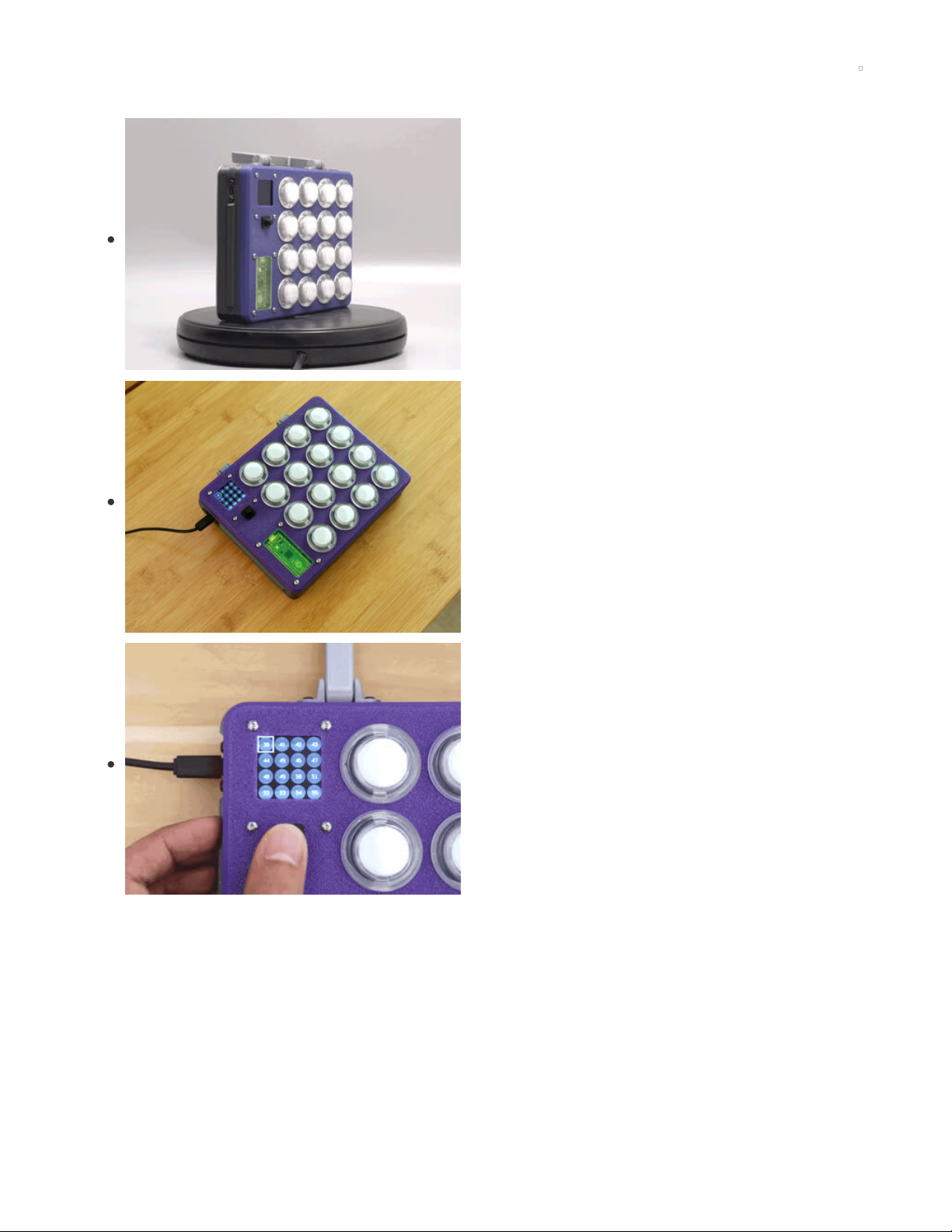
Intuitive UI/UX
The OLED screen shows the 16 buttons as little circles with
numbers. The numbers are the MIDI notes assigned to each
button. Use the joystick to select a button and edit the MIDI
note. In edit mode, the button will blink the LED, letting you
know it's been activated. While in edit mode, the buttons can
be pressed to compare MIDI notes.
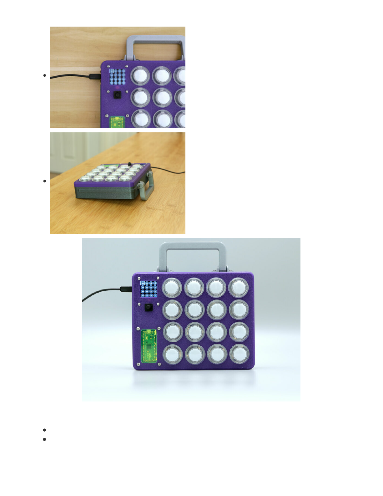
Kickstand Handle
Lunchbox vibes? Yes! The handle is 3d printed, print-in-place,
with no support material. Can you handle it? It also works
great as a kickstand to prop up the case.
Prerequisite Guides
Take a moment to walk through the following guides:
Raspberry Pi Pico RP2040 (https://adafru.it/RaD)
AW9523 GPIO Learn Guide (https://adafru.it/RaE)
© Adafruit Industries https://learn.adafruit.com/raspberry-pi-pico-led-arcade-button-midi-controller-fighter Page 6 of 63
Page 7
1.5" OLED Display Guide (https://adafru.it/RaF)
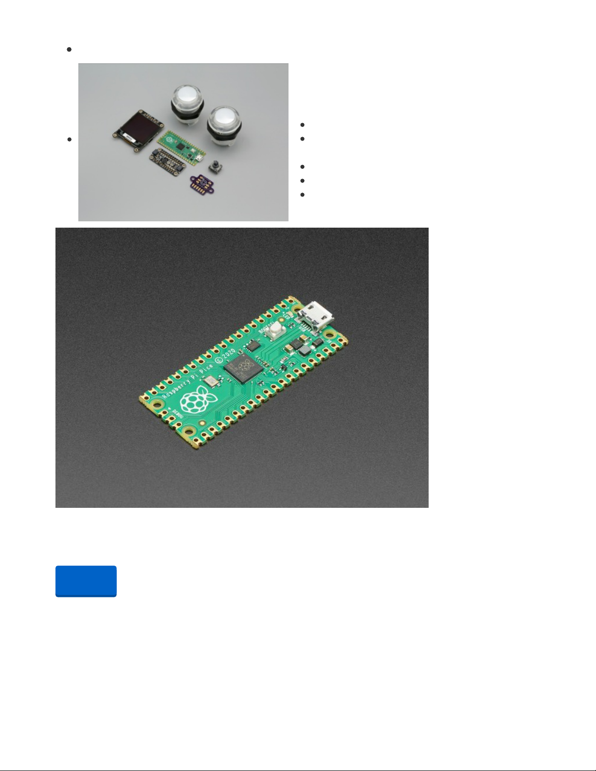
Parts from Adafruit
List of parts required for this build.
Raspberry Pi Pico (https://adafru.it/QOF)
AW9523 GPIO Expander and LED
Driver (https://adafru.it/RaG)
1.5" OLED Display (https://adafru.it/RaH)
5-way Navigation Switch (https://adafru.it/RaI)
30mm Arcade Button with LED (https://adafru.it/RaJ)
Raspberry Pi Pico RP2040
The Raspberry Pi foundation changed single-board computing when they released the Raspberry Pi
computer, now they're ready to...
Out of Stock
Your browser does not support the video tag.
Adafruit AW9523 GPIO Expander and LED Driver Breakout
Expand your project possibilities, with the Adafruit AW9523 GPIO Expander and LED Driver Breakout - a
cute and powerful I2C expander with a lot of tricks up its...
$4.95
In Stock
Out of
Stock
© Adafruit Industries https://learn.adafruit.com/raspberry-pi-pico-led-arcade-button-midi-controller-fighter Page 7 of 63
Page 8

Your browser does not support the video tag.
Adafruit Grayscale 1.5" 128x128 OLED Graphic Display
This OLED goes out to all the fans who want more pixels! Normally our 128x64 OLEDs are the biggest
ones we've stocked that can use I2C. This one is a whopping 128x128...
$22.50
In Stock
Your browser does not support the video tag.
Arcade Button with LED - 30mm Translucent Clear
A button is a button, and a switch is a switch, but these translucent arcade buttons are in a class of their
own. Particularly because they have LEDs built right...
$2.50
In Stock
1 x STEMMA QT / Qwiic JST SH 4-pin Cable - 100mm Long
STEMMA QT / Qwiic JST SH 4-pin Cable - 100mm Long
1 x Thru-hole 5-way Navigation switch
Thru-hole 5-way Navigation switch
1 x Panel Mount Extension USB Cable - Micro B Male to Micro B Female
Panel Mount Extension USB Cable - Micro B Male to Micro B Female
1 x Black Nylon Screw and Stand-off Set – M2.5 Thread
Black Nylon Screw and Stand-off Set – M2.5 Thread
1 x Silicone Cover Stranded-Core Ribbon Cable - 10 Wire 1 Meter Long - 28AWG Black
Silicone Cover Stranded-Core Ribbon Cable - 10 Wire 1 Meter Long - 28AWG Black
Hardware List
Screws, nuts and standoffs used in this build.
Handle
4x M3 x 10mm long screws
USB Extension Cable
2x M3 x 10mm long screws
2x M3 locknuts
OLED
4x M2.5 x 12mm long screws
Add to Cart
Add to Cart
Add to Cart
Add to Cart
Add to Cart
Add to Cart
Add to Cart
Add to Cart
© Adafruit Industries https://learn.adafruit.com/raspberry-pi-pico-led-arcade-button-midi-controller-fighter Page 8 of 63
Page 9

4x M2.5 nuts
5-way navigation PCB
2x M3 x 4mm long screws
PCB Mount
4x M3 x 12mm long FF standoffs
4x M2.5 x 8mm long FF standoffs
4x M2 x 6mm long FF standoffs
8x M3 x 6mm long screws
8x M2.5 x 4mm long screws
8x M2 x 4mm long screws
Author Credits
CAD by Noe Ruiz (https://adafru.it/GsA) and Code by Liz Clark (https://adafru.it/JEP).
Inspired by MIDI Fighter by DJTechTools (https://adafru.it/Rc5)
© Adafruit Industries https://learn.adafruit.com/raspberry-pi-pico-led-arcade-button-midi-controller-fighter Page 9 of 63
Page 10
Installing CircuitPython
CircuitPython (https://adafru.it/tB7) is a derivative of MicroPython (https://adafru.it/BeZ) designed to
simplify experimentation and education on low-cost microcontrollers. It makes it easier than ever to get
prototyping by requiring no upfront desktop software downloads. Simply copy and edit files on the
CIRCUITPY drive to iterate.
CircuitPython Quickstart
Follow this step-by-step to quickly get CircuitPython working on your board.
https://adafru.it/QaP
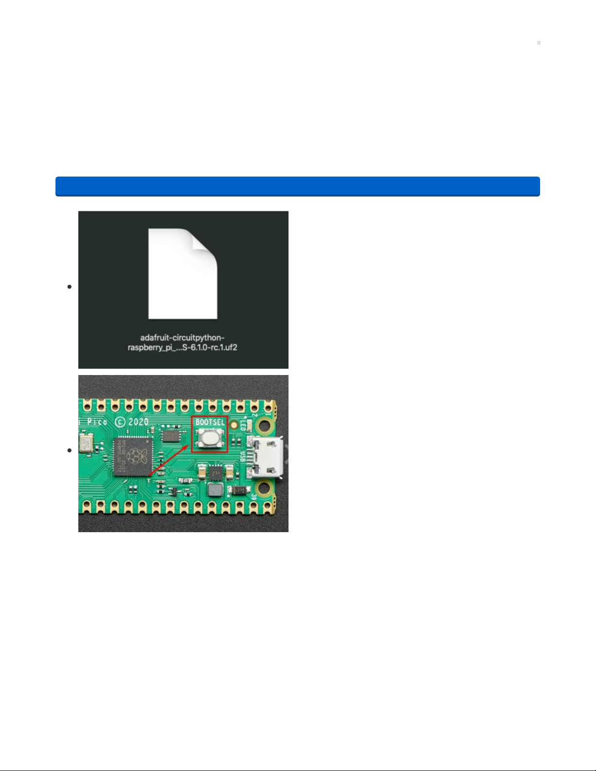
Click the link above and download the latest UF2 file.
Download and save it to your desktop (or wherever is handy).
Start with your Pico unplugged from USB. Hold down the
BOOTSEL button, and while continuing to hold it (don't let
go!), plug the Pico into USB. Continue to hold the BOOTSEL
button until the RPI-RP2 drive appears!
If the drive does not appear, unplug your Pico and go through
the above process again.
A lot of people end up using charge-only USB cables and it is
very frustrating! So make sure you have a USB cable you
know is good for data sync.
https://adafru.it/QaP
© Adafruit Industries https://learn.adafruit.com/raspberry-pi-pico-led-arcade-button-midi-controller-fighter Page 10 of 63
Page 11
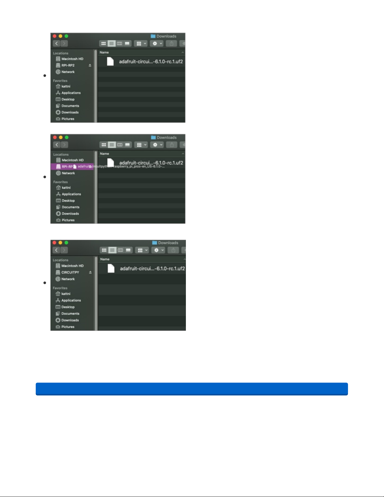
You will see a new disk drive appear called RPI-RP2.
Drag the adafruit_circuitpython_etc.uf2 file to RPI-RP2.
The RPI-RP2 drive will disappear and a new disk drive called
CIRCUITPY will appear.
That's it, you're done! :)
Flash Resetting UF2
If your Pico ever gets into a really
weird
state and doesn't even show up as a disk drive when installing
CircuitPython, try installing this 'nuke' UF2 which will do a 'deep clean' on your Flash Memory. You will
lose all the files on the board, but at least you'll be able to revive it! After nuking, re-install CircuitPython
https://adafru.it/QAJ
https://adafru.it/QAJ
© Adafruit Industries https://learn.adafruit.com/raspberry-pi-pico-led-arcade-button-midi-controller-fighter Page 11 of 63
Page 12

Coding the Raspberry Pi Pico MIDI Controller
Installing the CircuitPython Library Bundle
We're constantly updating and improving our libraries, so we don't (at this time) ship our CircuitPython
boards with the full library bundle. Instead, you can find example code in the guides for your board that
depends on external libraries. Some of these libraries may be available from us at Adafruit, some may be
written by community members!
Either way, as you start to explore CircuitPython, you'll want to know how to get libraries on board.
You can grab the latest Adafruit CircuitPython Bundle release by clicking the button below.
https://adafru.it/ENC
Once you've finished setting up your Raspberry Pi Pico with CircuitPython, you can add the libraries to
the lib folder of the Pico's CIRCUITPY drive which should appear when the board is plugged into your
computer via USB. Copy these folders:
adafruit_bus_device
adafruit_display_shapes
adafruit_display_text
adafruit_midi
adafruit_register
And these files:
adafruit_aw9523.mpy
adafruit_ssd1327.mpy
simpleio.mpy
To the CIRCUITPY flash drive /lib directory (create the directory if it doesn't exist).
Then, you can click on the Download: Project Zip link in the window below to download the code file.
import time
import board
import displayio
import terminalio
import adafruit_aw9523
import busio
import adafruit_ssd1327
import digitalio
from adafruit_display_text import label
from adafruit_display_shapes.circle import Circle
from adafruit_display_shapes.rect import Rect
import usb_midi
import adafruit_midi
from adafruit_midi.note_on import NoteOn
from adafruit_midi.note_off import NoteOff
displayio.release_displays()
# i2c setup, higher frequency for display refresh
i2c = busio.I2C(board.GP1, board.GP0, frequency=1000000)
https://adafru.it/ENC
© Adafruit Industries https://learn.adafruit.com/raspberry-pi-pico-led-arcade-button-midi-controller-fighter Page 12 of 63
Page 13

# i2c display setup
display_bus = displayio.I2CDisplay(i2c, device_address=0x3D)
# i2c AW9523 GPIO expander setup
aw = adafruit_aw9523.AW9523(i2c)
# MIDI setup as MIDI out device
midi = adafruit_midi.MIDI(midi_out=usb_midi.ports[1], out_channel=0)
# display dimensions
WIDTH = 128
HEIGHT = 128
# display setup
display = adafruit_ssd1327.SSD1327(display_bus, width=WIDTH, height=HEIGHT, brightness = 0.01)
# main display group, shows default GUI menu
splash = displayio.Group(max_size=60)
# group for circle icons
circle_group = displayio.Group(max_size=30)
# group for text labels on circles
text_group = displayio.Group(max_size=30)
# list of circle positions
spots = (
(16, 16),
(48, 16),
(80, 16),
(112, 16),
(16, 48),
(48, 48),
(80, 48),
(112, 48),
(16, 80),
(48, 80),
(80, 80),
(112, 80),
(16, 112),
(48, 112),
(80, 112),
(112, 112),
)
# creating the circles & pulling in positions from spots
for spot in spots:
circle = Circle(x0=spot[0], y0=spot[1], r=14, fill=0x888888)
# adding circles to their display group
circle_group.append(circle)
# square to show position on menu
rect = Rect(0, 0, 33, 33, fill=None, outline=0x00FF00, stroke = 3)
splash.append(circle_group)
splash.append(rect)
# strings and positions for the MIDI note text labels
texts = [
{'num': "60", 'pos': (12, 16)},
{'num': "61", 'pos': (44, 16)},
{'num': "62", 'pos': (76, 16)},
{'num': "63", 'pos': (108, 16)},
{'num': "64", 'pos': (12, 48)},
{'num': "65", 'pos': (44, 48)},
{'num': "66", 'pos': (76, 48)},
{'num': "67", 'pos': (108, 48)},
{'num': "68", 'pos': (12, 80)},
{'num': "69", 'pos': (44, 80)},
© Adafruit Industries https://learn.adafruit.com/raspberry-pi-pico-led-arcade-button-midi-controller-fighter Page 13 of 63
Page 14

{'num': "70", 'pos': (76, 80)},
{'num': "71", 'pos': (108, 80)},
{'num': "72", 'pos': (12, 112)},
{'num': "73", 'pos': (44, 112)},
{'num': "74", 'pos': (76, 112)},
{'num': "75", 'pos': (108, 112)},
]
text_labels = []
for text in texts:
text_area = label.Label(terminalio.FONT, text=text['num'], color=0xFFFFFF)
text_area.x = text['pos'][0]
text_area.y = text['pos'][1]
text_labels.append(text_area)
text_group.append(text_area)
splash.append(text_group)
# secondary display group, shows large circle when button is selected
big_splash = displayio.Group(max_size=60)
# large circle to fill display
big_circle = Circle(x0=64, y0=64, r=62, fill=0x888888)
big_splash.append(big_circle)
# large text to fill circle
big_text = label.Label(terminalio.FONT, text=' ', color=0xFFFFFF)
big_text.x = 43
big_text.y = 62
big_text.scale = 4
big_splash.append(big_text)
# array for LEDs on AW9523
leds = []
led_pins = [0, 1, 2, 3, 4, 5, 6, 7, 8, 9, 10, 11, 12, 13, 14, 15]
# setup to create the AW9523 outputs for LEDs
for led in led_pins:
led_pin = aw.get_pin(led)
led_pin.direction = digitalio.Direction.OUTPUT
leds.append(led_pin)
# button pins, all pins in order skipping GP15
note_pins = [board.GP7, board.GP8, board.GP9, board.GP10, board.GP11,
board.GP12, board.GP13, board.GP14, board.GP16, board.GP17,
board.GP18, board.GP19, board.GP20, board.GP21, board.GP22, board.GP26]
note_buttons = []
for pin in note_pins:
note_pin = digitalio.DigitalInOut(pin)
note_pin.direction = digitalio.Direction.INPUT
note_pin.pull = digitalio.Pull.UP
note_buttons.append(note_pin)
# note states
note0_pressed = False
note1_pressed = False
note2_pressed = False
note3_pressed = False
note4_pressed = False
note5_pressed = False
note6_pressed = False
note7_pressed = False
note8_pressed = False
© Adafruit Industries https://learn.adafruit.com/raspberry-pi-pico-led-arcade-button-midi-controller-fighter Page 14 of 63
Page 15

note9_pressed = False
note10_pressed = False
note11_pressed = False
note12_pressed = False
note13_pressed = False
note14_pressed = False
note15_pressed = False
# array of note states
note_states = [note0_pressed, note1_pressed, note2_pressed, note3_pressed,
note4_pressed, note5_pressed, note6_pressed, note7_pressed,
note8_pressed, note9_pressed, note10_pressed, note11_pressed,
note12_pressed, note13_pressed, note14_pressed, note15_pressed]
# pins for 5-way switch
select = digitalio.DigitalInOut(board.GP6)
up = digitalio.DigitalInOut(board.GP5)
down = digitalio.DigitalInOut(board.GP4)
left = digitalio.DigitalInOut(board.GP3)
right = digitalio.DigitalInOut(board.GP2)
# array for 5-way switch
joystick = [select, up, down, left, right]
for joy in joystick:
joy.direction = digitalio.Direction.INPUT
joy.pull = digitalio.Pull.UP
# states for 5-way switch
select_state = None
up_state = None
down_state = None
left_state = None
right_state = None
midi_state = None
# coordinates for navigating main GUI
select_x = [0, 32, 64, 96]
select_y = [0, 32, 64, 96]
# y coordinate for 5-way switch navigation
y_pos = 0
# x coordinate for 5-way switch navigation
x_pos = 0
sub_state = False
# default midi number
midi_num = 60
# default MIDI button
button_num = 0
# default MIDI button position
button_pos = 0
# check for blinking LED
led_check = None
# time.monotonic() device
clock = time.monotonic()
# coordinates for tracking location of 5-way switch
up_scroll = 0
down_scroll = 0
left_scroll = 0
right_scroll = 0
switch_coordinates = [(0, 0), (1, 0), (2, 0), (3, 0), (0, 1), (1, 1), (2, 1), (3, 1), (0, 2),
(1, 2), (2, 2), (3, 2), (0, 3), (1, 3), (2, 3), (3, 3)]
# array of default MIDI notes
midi_notes = [60, 61, 62, 63, 64, 65, 66, 67, 68, 69, 70, 71, 72, 73, 74, 75]
© Adafruit Industries https://learn.adafruit.com/raspberry-pi-pico-led-arcade-button-midi-controller-fighter Page 15 of 63
Page 16

# show main display GUI
display.show(splash)
while True:
# debouncing for 5-way switch positions
if up.value and up_state == "pressed":
print("Button pressed.")
up_state = None
if down.value and down_state == "pressed":
print("Button pressed.")
down_state = None
if left.value and left_state == "pressed":
print("Button pressed.")
left_state = None
if right.value and right_state == "pressed":
print("Button pressed.")
right_state = None
if select.value and select_state == "pressed":
print("Button pressed.")
select_state = None
# MIDI input
for i in range(16):
buttons = note_buttons[i]
# if button is pressed...
if not buttons.value and note_states[i] is False:
# send the MIDI note and light up the LED
midi.send(NoteOn(midi_notes[i], 120))
note_states[i] = True
leds[i].value = True
# if the button is released...
if buttons.value and note_states[i] is True:
# stop sending the MIDI note and turn off the LED
midi.send(NoteOff(midi_notes[i], 120))
note_states[i] = False
leds[i].value = False
# if we're on the main GUI page
if not sub_state:
# if you press up on the 5-way switch...
if not up.value and up_state is None:
up_state = "pressed"
# track the switch's position
up_scroll -= 1
if up_scroll < 0:
up_scroll = 3
y_pos = up_scroll
down_scroll = up_scroll
# if you press down on the 5-way switch...
if not down.value and down_state is None:
down_state = "pressed"
# track the switch's position
down_scroll += 1
if down_scroll > 3:
down_scroll = 0
y_pos = down_scroll
up_scroll = down_scroll
# if you press left on the 5-way switch...
if not left.value and left_state is None:
# print("scroll", down_scroll)
left_state = "pressed"
# track the switch's position
© Adafruit Industries https://learn.adafruit.com/raspberry-pi-pico-led-arcade-button-midi-controller-fighter Page 16 of 63
Page 17

left_scroll -= 1
if left_scroll < 0:
left_scroll = 3
x_pos = left_scroll
right_scroll = left_scroll
# if you press right on the 5-way switch...
if not right.value and right_state is None:
# print("scroll", down_scroll)
right_state = "pressed"
# track the switch's position
right_scroll += 1
if right_scroll > 3:
right_scroll = 0
x_pos = right_scroll
left_scroll = right_scroll
# update square's position on the GUI
rect.y = select_y[y_pos]
rect.x = select_x[x_pos]
# update the currently highlighted button on the GUI
for coords in switch_coordinates:
if x_pos == coords[0] and y_pos == coords[1]:
button_pos = switch_coordinates.index(coords)
# print(button_pos)
button_num = text_labels[button_pos].text
# if you press select on the 5-way switch...
if not select.value and select_state is None:
select_state = "pressed"
# grab the selected button's MIDI note
midi_num = int(button_num)
# change into the secondary GUI menu
sub_state = True
# if an arcade button is selected to change the MIDI note...
if sub_state:
# display the secondary GUI menu
display.show(big_splash)
# display the selected button's MIDI note
big_text.text = str(midi_num)
# blink the selected button's LED without pausing the loop
if (time.monotonic() > (clock + 1)) and led_check is None:
leds[button_pos].value = True
led_check = True
clock = time.monotonic()
if (time.monotonic() > (clock + 1)) and led_check is True:
leds[button_pos].value = False
led_check = None
clock = time.monotonic()
# blocks the MIDI number from being set above 128
if midi_num >= 128:
midi_num = 128
# blocks the MIDI number from being set below 0
if midi_num <= 0:
midi_num = 0
# if you press right on the 5-way switch...
if not right.value and right_state is None:
# increase the MIDI number
midi_num += 1
© Adafruit Industries https://learn.adafruit.com/raspberry-pi-pico-led-arcade-button-midi-controller-fighter Page 17 of 63
Page 18

right_state = "pressed"
# if you press up on the 5-way switch...
if not up.value and up_state is None:
# increase the MIDI number
midi_num += 1
up_state = "pressed"
# if you press left on the 5-way switch...
if not left.value and left_state is None:
# decrease the MIDI number
midi_num -= 1
left_state = "pressed"
# if you press down on the 5-way switch...
if not down.value and down_state is None:
# decrease the MIDI number
midi_num -= 1
down_state = "pressed"
# update arcade button's MIDI note
# allows you to check note while you're adjusting it
midi_notes[button_pos] = midi_num
# if you press select on the 5-way switch...
if not select.value and select_state is None:
select_state = "pressed"
# change back to main menu mode
sub_state = False
# update new MIDI number text label
text_labels[button_pos].text = str(midi_num)
# show main GUI display
display.show(splash)
# turn off blinking LED
leds[button_pos].value = False
Review
Make sure you've followed these steps:
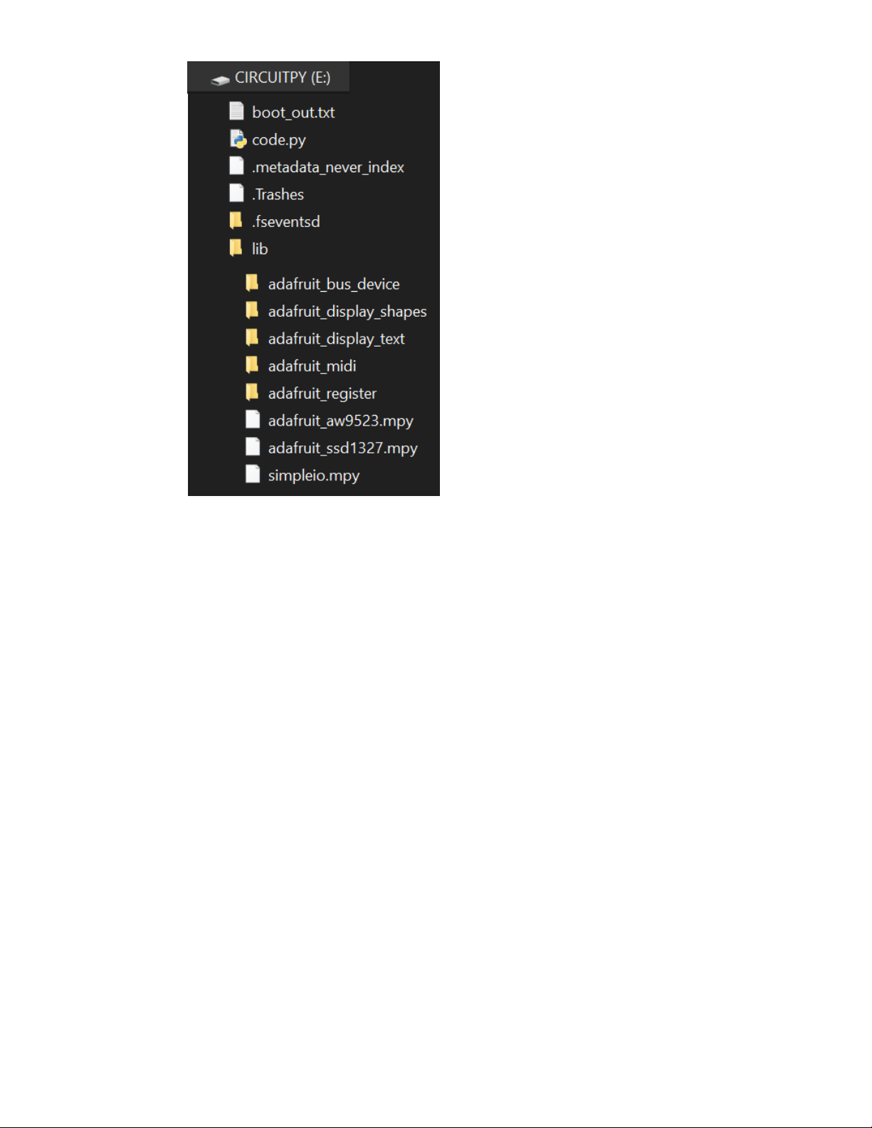
Loaded all the required library files and directories into the CIRCUITPY /lib directory
Copied code.py to the main (root) directory of the CIRCUITPY drive
Your Raspberry Pi Pico CIRCUITPY drive should look like this after you load the libraries and code.py file:
© Adafruit Industries https://learn.adafruit.com/raspberry-pi-pico-led-arcade-button-midi-controller-fighter Page 18 of 63
Page 19
© Adafruit Industries https://learn.adafruit.com/raspberry-pi-pico-led-arcade-button-midi-controller-fighter Page 19 of 63
Page 20

CircuitPython Code Walkthrough
Import the Libraries
First, the CircuitPython libraries are imported.
import time
import board
import displayio
import terminalio
import adafruit_aw9523
import busio
import adafruit_ssd1327
import digitalio
from adafruit_display_text import label
from adafruit_display_shapes.circle import Circle
from adafruit_display_shapes.rect import Rect
import usb_midi
import adafruit_midi
from adafruit_midi.note_on import NoteOn
from adafruit_midi.note_off import NoteOff
I2C and MIDI Setup
I2C is setup to use the Pico's GP0 and GP1 pins. You have two I2C devices in this project: the Grayscale
1.5" 128x128 OLED Display and the AW9523 GPIO Expander and LED Driver.
midi is also setup to act as a USB MIDI output device. midi_out sends notes out from the device.
# i2c setup, higher frequency for display refresh
i2c = busio.I2C(board.GP1, board.GP0, frequency=1000000)
# i2c display setup
display_bus = displayio.I2CDisplay(i2c, device_address=0x3D)
# i2c AW9523 GPIO expander setup
aw = adafruit_aw9523.AW9523(i2c)
# MIDI setup as MIDI out device
midi = adafruit_midi.MIDI(midi_out=usb_midi.ports[1], out_channel=0)
Display Setup
This project utilizes a graphical user interface (GUI) to let you change the MIDI note numbers assigned to
each of the arcade buttons. Each button is represented on the display as a circle. The code uses the
Circle object from the adafruit_display_shapes library to easily draw circles on the display without having
to import a bitmap.
spots holds the list of coordinates for each of the circles and the for statement creates each circle and
assigns them to the correct coordinate.
A rectangle is also created using the Rect object from the adafruit_display_shapes library. This rectangle is
used to highlight the currently selected circle on the display.
© Adafruit Industries https://learn.adafruit.com/raspberry-pi-pico-led-arcade-button-midi-controller-fighter Page 20 of 63
Page 21

# display dimensions
WIDTH = 128
HEIGHT = 128
# display setup
display = adafruit_ssd1327.SSD1327(display_bus, width=WIDTH, height=HEIGHT, brightness = 0.01)
# main display group, shows default GUI menu
splash = displayio.Group(max_size=60)
# group for circle icons
circle_group = displayio.Group(max_size=30)
# group for text labels on circles
text_group = displayio.Group(max_size=30)
# list of circle positions
spots = (
(16, 16),
(48, 16),
(80, 16),
(112, 16),
(16, 48),
(48, 48),
(80, 48),
(112, 48),
(16, 80),
(48, 80),
(80, 80),
(112, 80),
(16, 112),
(48, 112),
(80, 112),
(112, 112),
)
# creating the circles & pulling in positions from spots
for spot in spots:
circle = Circle(x0=spot[0], y0=spot[1], r=14, fill=0x888888)
# adding circles to their display group
circle_group.append(circle)
# square to show position on menu
rect = Rect(0, 0, 33, 33, fill=None, outline=0x00FF00, stroke = 3)
splash.append(circle_group)
splash.append(rect)
MIDI Note Labels
Each circle has text that shows the currently assigned MIDI note number for each arcade button. This
information is stored in texts along with the coordinates for each string's location. The for statement
creates each text object, pulling this information from texts , and stores them in the text_labels array.
© Adafruit Industries https://learn.adafruit.com/raspberry-pi-pico-led-arcade-button-midi-controller-fighter Page 21 of 63
Page 22

# strings and positions for the MIDI note text labels
texts = [
{'num': "60", 'pos': (12, 16)},
{'num': "61", 'pos': (44, 16)},
{'num': "62", 'pos': (76, 16)},
{'num': "63", 'pos': (108, 16)},
{'num': "64", 'pos': (12, 48)},
{'num': "65", 'pos': (44, 48)},
{'num': "66", 'pos': (76, 48)},
{'num': "67", 'pos': (108, 48)},
{'num': "68", 'pos': (12, 80)},
{'num': "69", 'pos': (44, 80)},
{'num': "70", 'pos': (76, 80)},
{'num': "71", 'pos': (108, 80)},
{'num': "72", 'pos': (12, 112)},
{'num': "73", 'pos': (44, 112)},
{'num': "74", 'pos': (76, 112)},
{'num': "75", 'pos': (108, 112)},
]
text_labels = []
for text in texts:
text_area = label.Label(terminalio.FONT, text=text['num'], color=0xFFFFFF)
text_area.x = text['pos'][0]
text_area.y = text['pos'][1]
text_labels.append(text_area)
text_group.append(text_area)
splash.append(text_group)
Secondary GUI Menu
In addition to the main GUI, there is a secondary GUI. When you select an arcade button's MIDI note to
edit, the display shows a large circle with large text showing the MIDI note number that you're editing.
This secondary GUI is stored in big_splash .
# secondary display group, shows large circle when button is selected
big_splash = displayio.Group(max_size=60)
# large circle to fill display
big_circle = Circle(x0=64, y0=64, r=62, fill=0x888888)
big_splash.append(big_circle)
# large text to fill circle
big_text = label.Label(terminalio.FONT, text=' ', color=0xFFFFFF)
big_text.x = 43
big_text.y = 62
big_text.scale = 4
big_splash.append(big_text)
LEDs with the AW9523
The arcade button's LEDs are controlled with the AW9523 GPIO expander. The I/O of the AW9523 is
accessed with aw.get_pin(pin_number) . The pin numbers are stored in the led_pins array and the for
statement sets up the pins to be outputs.
© Adafruit Industries https://learn.adafruit.com/raspberry-pi-pico-led-arcade-button-midi-controller-fighter Page 22 of 63
Page 23

# array for LEDs on AW9523
leds = []
led_pins = [0, 1, 2, 3, 4, 5, 6, 7, 8, 9, 10, 11, 12, 13, 14, 15]
# setup to create the AW9523 outputs for LEDs
for led in led_pins:
led_pin = aw.get_pin(led)
led_pin.direction = digitalio.Direction.OUTPUT
leds.append(led_pin)
Arcade Button Pins
The pins used for the arcade buttons are stored in the note_pins array. They are setup to be digital inputs
in the for statement and are then stored in the note_buttons array.
Each arcade button has a state setup for debouncing. These states are stored in the note_states array.
# button pins, all pins in order skipping GP15
note_pins = [board.GP7, board.GP8, board.GP9, board.GP10, board.GP11,
board.GP12, board.GP13, board.GP14, board.GP16, board.GP17,
board.GP18, board.GP19, board.GP20, board.GP21, board.GP22, board.GP26]
note_buttons = []
for pin in note_pins:
note_pin = digitalio.DigitalInOut(pin)
note_pin.direction = digitalio.Direction.INPUT
note_pin.pull = digitalio.Pull.UP
note_buttons.append(note_pin)
# note states
note0_pressed = False
note1_pressed = False
note2_pressed = False
note3_pressed = False
note4_pressed = False
note5_pressed = False
note6_pressed = False
note7_pressed = False
note8_pressed = False
note9_pressed = False
note10_pressed = False
note11_pressed = False
note12_pressed = False
note13_pressed = False
note14_pressed = False
note15_pressed = False
# array of note states
note_states = [note0_pressed, note1_pressed, note2_pressed, note3_pressed,
note4_pressed, note5_pressed, note6_pressed, note7_pressed,
note8_pressed, note9_pressed, note10_pressed, note11_pressed,
note12_pressed, note13_pressed, note14_pressed, note15_pressed]
5-Way Navigation Switch
The GUI is navigated with a 5-way switch. This allows you to move in all directions around the screen and
select the arcade button that you want to edit. The digital pins for the 5-way switch are stored in the
joystick array and are setup as inputs in the for statement.
© Adafruit Industries https://learn.adafruit.com/raspberry-pi-pico-led-arcade-button-midi-controller-fighter Page 23 of 63
Page 24

# pins for 5-way switch
select = digitalio.DigitalInOut(board.GP6)
up = digitalio.DigitalInOut(board.GP5)
down = digitalio.DigitalInOut(board.GP4)
left = digitalio.DigitalInOut(board.GP3)
right = digitalio.DigitalInOut(board.GP2)
# array for 5-way switch
joystick = [select, up, down, left, right]
for joy in joystick:
joy.direction = digitalio.Direction.INPUT
joy.pull = digitalio.Pull.UP
State Machines
There are a few state machines used in the code. Each pin for the 5-way switch has a state for
debouncing. The other states' functionality is commented below.
# states for 5-way switch
select_state = None
up_state = None
down_state = None
left_state = None
right_state = None
midi_state = None
# coordinates for navigating main GUI
select_x = [0, 32, 64, 96]
select_y = [0, 32, 64, 96]
# y coordinate for 5-way switch navigation
y_pos = 0
# x coordinate for 5-way switch navigation
x_pos = 0
sub_state = False
# default midi number
midi_num = 60
# default MIDI button
button_num = 0
# default MIDI button position
button_pos = 0
# check for blinking LED
led_check = None
# time.monotonic() device
clock = time.monotonic()
GUI Navigation Setup
The navigation for the GUI works by counting the number of times each directional input from the 5-way
switch is pressed. The combinations of these counts are stored in the switch_coordinates array to act as x
and y coordinates on the GUI. It's helpful to think of the arcade buttons as a 4x4 grid.
# coordinates for tracking location of 5-way switch
up_scroll = 0
down_scroll = 0
left_scroll = 0
right_scroll = 0
switch_coordinates = [(0, 0), (1, 0), (2, 0), (3, 0), (0, 1), (1, 1), (2, 1), (3, 1), (0, 2),
(1, 2), (2, 2), (3, 2), (0, 3), (1, 3), (2, 3), (3, 3)]
© Adafruit Industries https://learn.adafruit.com/raspberry-pi-pico-led-arcade-button-midi-controller-fighter Page 24 of 63
Page 25

MIDI Note Array
The midi_notes array holds the default MIDI notes that are assigned to the arcade buttons. If you want to
change the MIDI notes that are loaded after powering the MIDI Fighter, you'll want to edit this array.
# array of default MIDI notes
midi_notes = [60, 61, 62, 63, 64, 65, 66, 67, 68, 69, 70, 71, 72, 73, 74, 75]
The Loop
Switch Debouncing
The loop begins by debouncing the five inputs of the 5-way switch.
while True:
# debouncing for 5-way switch positions
if up.value and up_state == "pressed":
print("Button pressed.")
up_state = None
if down.value and down_state == "pressed":
print("Button pressed.")
down_state = None
if left.value and left_state == "pressed":
print("Button pressed.")
left_state = None
if right.value and right_state == "pressed":
print("Button pressed.")
right_state = None
if select.value and select_state == "pressed":
print("Button pressed.")
select_state = None
MIDI Input
The arcade buttons send their assigned MIDI note number out with a MIDI NoteOn message when they
are pressed. Additionally, when you press an arcade button, its LED lights up with the AW9523. When the
arcade button is released, a NoteOff message is sent and the LED is turned off.
# MIDI input
for i in range(16):
buttons = note_buttons[i]
# if button is pressed...
if not buttons.value and note_states[i] is False:
# send the MIDI note and light up the LED
midi.send(NoteOn(midi_notes[i], 120))
note_states[i] = True
leds[i].value = True
# if the button is released...
if buttons.value and note_states[i] is True:
# stop sending the MIDI note and turn off the LED
midi.send(NoteOff(midi_notes[i], 120))
note_states[i] = False
leds[i].value = False
Main GUI Navigation
The main GUI is navigated using the 5-way switch. Every time you press up, down, left or right, the values
of up_scroll , down_scroll , left_scroll or right_scroll are updated with a count between 0 and 3 . These
values are used as coordinates to track where you are on the GUI.
© Adafruit Industries https://learn.adafruit.com/raspberry-pi-pico-led-arcade-button-midi-controller-fighter Page 25 of 63
Page 26

y_pos and x_pos also hold these values and are used as array indexes to update the highlighting
square's position on the GUI.
# if we're on the main GUI page
if not sub_state:
# if you press up on the 5-way switch...
if not up.value and up_state is None:
up_state = "pressed"
# track the switch's position
up_scroll -= 1
if up_scroll < 0:
up_scroll = 3
y_pos = up_scroll
down_scroll = up_scroll
# if you press down on the 5-way switch...
if not down.value and down_state is None:
down_state = "pressed"
# track the switch's position
down_scroll += 1
if down_scroll > 3:
down_scroll = 0
y_pos = down_scroll
up_scroll = down_scroll
# if you press left on the 5-way switch...
if not left.value and left_state is None:
# print("scroll", down_scroll)
left_state = "pressed"
# track the switch's position
left_scroll -= 1
if left_scroll < 0:
left_scroll = 3
x_pos = left_scroll
right_scroll = left_scroll
# if you press right on the 5-way switch...
if not right.value and right_state is None:
# print("scroll", down_scroll)
right_state = "pressed"
# track the switch's position
right_scroll += 1
if right_scroll > 3:
right_scroll = 0
x_pos = right_scroll
left_scroll = right_scroll
# update square's position on the GUI
rect.y = select_y[y_pos]
rect.x = select_x[x_pos]
Track the Button
In order to keep track of which button on the GUI is highlighted, the x_pos and y_pos values are
compared to the switch_coordinates array to track which button is highlighted on the screen. This is how
that button's value can then be affected in the secondary GUI.
button_num is used to track the MIDI note number for the currently selected button.
© Adafruit Industries https://learn.adafruit.com/raspberry-pi-pico-led-arcade-button-midi-controller-fighter Page 26 of 63
Page 27

# update the currently highlighted button on the GUI
for coords in switch_coordinates:
if x_pos == coords[0] and y_pos == coords[1]:
button_pos = switch_coordinates.index(coords)
# print(button_pos)
button_num = text_labels[button_pos].text
Selecting a Button to Edit
When you have navigated to your chosen arcade button's position, you can press select on the 5-way
switch to enter the editing mode for that button. midi_num grabs the highlighted button's MIDI note
number so that you'll be able to edit and update that number.
# if you press select on the 5-way switch...
if not select.value and select_state is None:
select_state = "pressed"
# grab the selected button's MIDI note
midi_num = int(button_num)
# change into the secondary GUI menu
sub_state = True
Secondary GUI: Edit the Arcade Button's MIDI Note Number
When you enter the editing mode, the secondary GUI is displayed. Your selected button's LED will also
blink on and off until you exit this mode. The blinking is done using time.monotonic() so that it doesn't
interrupt anything else happening in the loop.
# if an arcade button is selected to change the MIDI note...
if sub_state:
# display the secondary GUI menu
display.show(big_splash)
# display the selected button's MIDI note
big_text.text = midi_num
# blink the selected button's LED without pausing the loop
if (time.monotonic() > (clock + 1)) and led_check is None:
leds[button_pos].value = True
led_check = True
clock = time.monotonic()
if (time.monotonic() > (clock + 1)) and led_check is True:
leds[button_pos].value = False
led_check = None
clock = time.monotonic()
MIDI Note Number Range
A MIDI note range is setup so that you don't go below 0 or above 128.
# blocks the MIDI number from being set above 128
if midi_num >= 128:
midi_num = 128
# blocks the MIDI number from being set below 0
if midi_num <= 0:
midi_num = 0
Adjusting the MIDI Note
The MIDI note number can be increased by pressing up or right with the 5-way switch and decreased by
pressing down or left with the 5-way switch. The value of midi_num is either increased or decreased by 1
© Adafruit Industries https://learn.adafruit.com/raspberry-pi-pico-led-arcade-button-midi-controller-fighter Page 27 of 63
Page 28

depending on the input.
# if you press right on the 5-way switch...
if not right.value and right_state is None:
# increase the MIDI number
midi_num += 1
right_state = "pressed"
# if you press up on the 5-way switch...
if not up.value and up_state is None:
# increase the MIDI number
midi_num += 1
up_state = "pressed"
# if you press left on the 5-way switch...
if not left.value and left_state is None:
# decrease the MIDI number
midi_num -= 1
left_state = "pressed"
# if you press down on the 5-way switch...
if not down.value and down_state is None:
# decrease the MIDI number
midi_num -= 1
down_state = "pressed"
Update the MIDI Note
The value of the selected arcade button's MIDI note is adjusted in real time. This allows you to play the
note while you're adjusting to make sure it's the correct note.
# update arcade button's MIDI note
# allows you to check note while you're adjusting it
midi_notes[button_pos] = midi_num
Save the New MIDI Note
After deciding on your MIDI note, you can press select again on the 5-way switch to save your choice.
This updates the text label on the main GUI, stops the LED from blinking and brings you back to the main
GUI on the display.
# if you press select on the 5-way switch...
if not select.value and select_state is None:
select_state = "pressed"
# change back to main menu mode
sub_state = False
# update new MIDI number text label
text_labels[button_pos].text = midi_num
# show main GUI display
display.show(splash)
# turn off blinking LED
leds[button_pos].value = False
© Adafruit Industries https://learn.adafruit.com/raspberry-pi-pico-led-arcade-button-midi-controller-fighter Page 28 of 63
Page 29
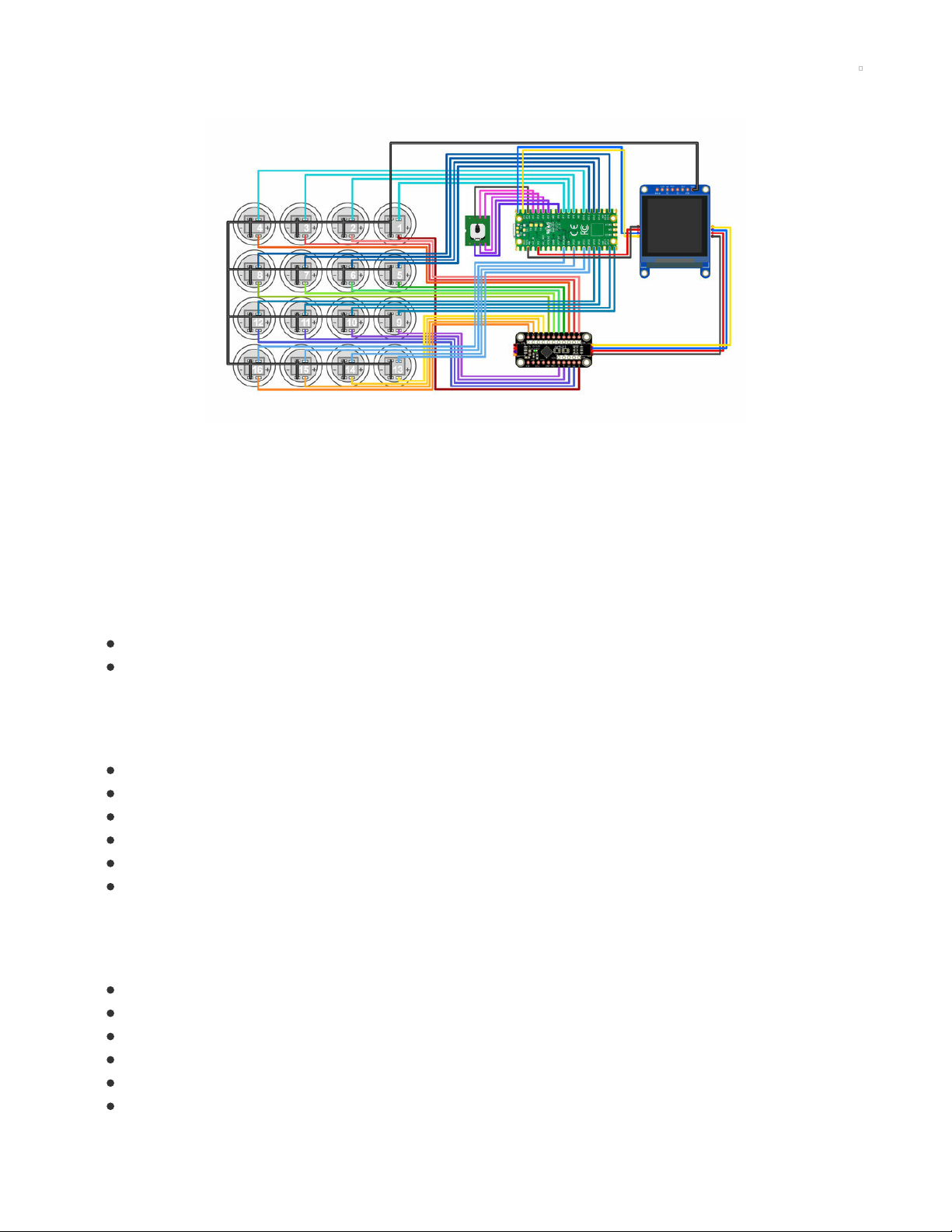
Circuit Diagram
The diagram below provides a visual reference for wiring of the components. This diagram was created
using the software package Fritzing (https://adafru.it/oEP).
Adafruit Library for Fritzing
Use Adafruit's Fritzing parts library to create circuit diagrams for your projects. Download the library or just
grab individual parts. Get the library and parts from GitHub - Adafruit Fritzing Parts (https://adafru.it/AYZ).
STEMMA QT Connections
The following components are connected via STEMMA QT cables.
Raspberry Pi Pico – 1.5" OLED
1.5" OLED – AW9523 LED Driver
5-way navigation switch
The 5-way navigation switch is connected to the following pins on the Raspberry Pi Pico.
Ground – Ground
Select – GP6
Up – GP2
Down – GP3
Left – GP4
Right – GP5
Button Switches
The switches from the buttons are connected to the following pins on the Raspberry Pi Pico.
Button 1 – GP7
Button 2 – GP8
Button 3 – GP9
Button 4 – GP10
Button 5 – GP11
Button 6 – GP12
© Adafruit Industries https://learn.adafruit.com/raspberry-pi-pico-led-arcade-button-midi-controller-fighter Page 29 of 63
Page 30

Button 7 – GP13
Button 8 – GP14
Button 9 – GP16
Button 10 – GP17
Button 11 – GP18
Button 12 – GP19
Button 13 – GP20
Button 14 – GP21
Button 15 – GP22
Button 16 – GP26
Button LEDs
The LEDs from the buttons are connected to the following pins on the AW9523 LED Driver.
Button 1 – Pin 0
Button 2 – Pin 1
Button 3 – Pin 2
Button 4 – Pin 3
Button 5 – Pin 4
Button 6 – Pin 5
Button 7 – Pin 6
Button 8 – Pin 7
Button 9 – Pin 8
Button 10 – Pin 9
Button 11 – Pin 10
Button 12 – Pin 11
Button 13 – Pin 12
Button 14 – Pin 13
Button 15 – Pin 14
Button 16 – Pin 15
© Adafruit Industries https://learn.adafruit.com/raspberry-pi-pico-led-arcade-button-midi-controller-fighter Page 30 of 63
Page 31
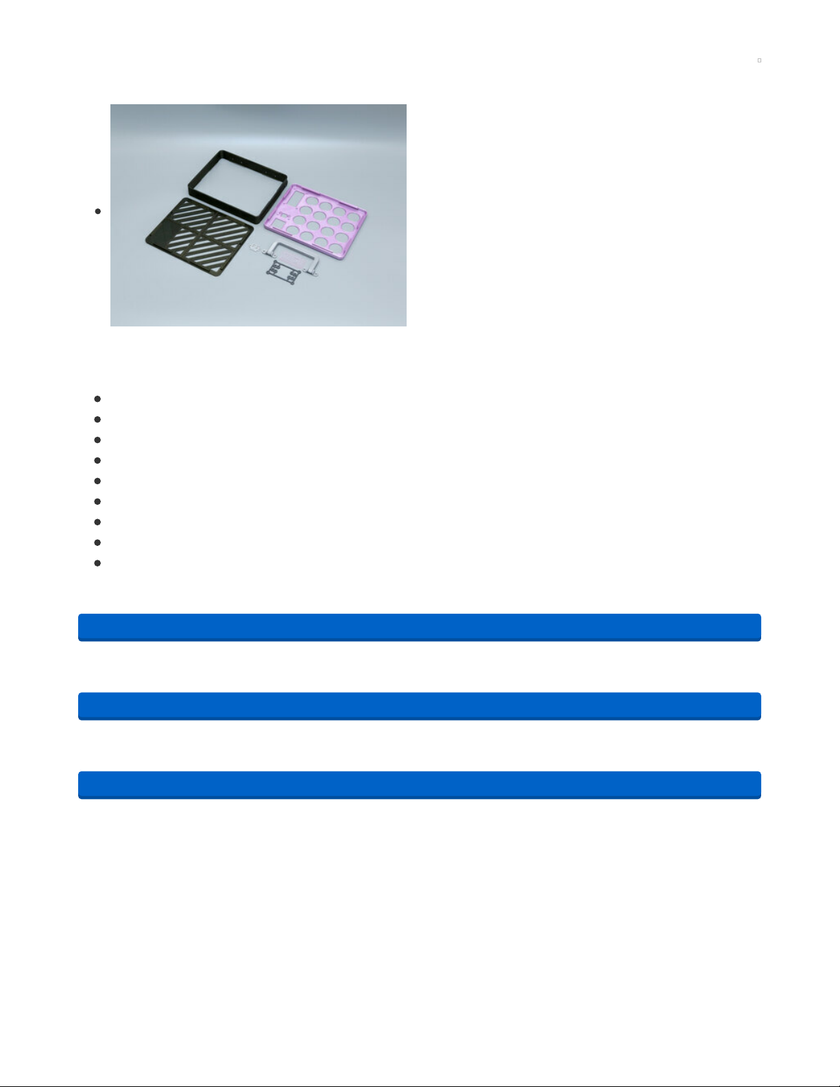
3D Printing
CAD Files
STL files for 3D printing are oriented to print "as-is" on FDM
style machines. Parts are designed to 3D print without any
support material. Original design source may be downloaded
using the links below.
CAD Parts List
List of the 3D printed parts.
case-top.stl
case-frame.stl
case-bottom.stl
case-handle.stl
PCB-mount.stl
5way-switch-pcb.stl
window-print-blank.stl
window-printed-midi-logo.stl
case-bottom-window.stl
Opens in the web browser to preview 3D models. More download options available in the preview page.
https://adafru.it/RaL
Includes a STEP and Fusion 360 Archive.
https://adafru.it/RaM
Grab just the STL files for 3D printing.
https://adafru.it/RaN
https://adafru.it/RaL
https://adafru.it/RaM
https://adafru.it/RaN
© Adafruit Industries https://learn.adafruit.com/raspberry-pi-pico-led-arcade-button-midi-controller-fighter Page 31 of 63
Page 32

Window Options
The top cover is designed to have a window. This allows you
to peek through and see the Raspberry Pi Pico. The window
can be 3D printed using transparent filament.
Have fun with this! Add your own text, logo or stickers / vinyl
decals. Personalize it, make it yours.
Optionally, the window can be made from acrylic using a
laser cutter or CNC mill.
Install Window
The window features a lip to prevent it from being pressed all
the way through the cut out in the top cover.
The window is installed through the bottom side of the top
cover. It should have a tight fit.
Optionally glue in place to permanently secure to the top
cover.
© Adafruit Industries https://learn.adafruit.com/raspberry-pi-pico-led-arcade-button-midi-controller-fighter Page 32 of 63
Page 33

Install Handle to Frame
Use the following hardware to secure the handle to the
frame.
4x M3 x 10mm screws
4x M3 locknuts
Handle Kickstand
The handle features an angled surface for propping up the
case. Reference the image for the correct placement of the
handle. Use the USB opening on the side of the frame as an
indicator for the correct orientation.
Secure Handle to Frame
Insert the M3 screws through the mounting holes in the
hinges. Then, insert the screws through the holes on the side
of the frame. Install and fasten the locknuts onto the screws.
Use pliers to tightly secure the screw and nuts.
© Adafruit Industries https://learn.adafruit.com/raspberry-pi-pico-led-arcade-button-midi-controller-fighter Page 33 of 63
Page 34

Install Bottom Cover to Frame
The bottom cover snap fits onto the frame. The bottom cover
features snap fit clips that are designed to lock onto the
edges inside the frame.
Reference the image for the correct orientation.
Fusion 360 CAD Tutorial
Taking a look at designing a hinged handle that can be 3d printed in place with no supports. The design
features a handle that can rotate 180 degrees. This handle is apart of the enclosure for a MIDI controller.
Driven with user parameters, the handle can be customized to fit any project.
© Adafruit Industries https://learn.adafruit.com/raspberry-pi-pico-led-arcade-button-midi-controller-fighter Page 34 of 63
Page 35

PCB Mount Assembly
Hardware for PCB Mount
Use the following hardware for assembling the PCB mount.
4x M3 x 12mm long FF standoffs
4 x M2.5mm x 8mm long FF standoffs
4x M2 x 6mm long FF standoffs
8x M3 x 6mm screws
8x M2 x 4mm screws
8x M2.5 x 4mm screws
Install M3 hardware
Insert M3 screws through the mounting holes on the outer
perimeter of the PCB mount. Fasten the M3 standoffs onto
the thread of the screw.
Install M2 Hardware
Insert M2 screws through the mounting holes that are near
the M3 standoffs. Fasten the M2 standoffs onto the threads of
the screws.
© Adafruit Industries https://learn.adafruit.com/raspberry-pi-pico-led-arcade-button-midi-controller-fighter Page 35 of 63
Page 36

Install M2.5 Hardware
Flip the PCB over and insert the M2.5 screws through the
remaining mounting holes. Fasten the M2.5 standoffs onto
the threads of the screws. The M2.5 standoffs should be
facing the opposite side. Reference the image for correct
placement.
Assembled PCB Mount
Double check the standoffs are tightly fastened and installed
in the correct mounting holes. Reference the images, click the
thumbnail to enlarge.
© Adafruit Industries https://learn.adafruit.com/raspberry-pi-pico-led-arcade-button-midi-controller-fighter Page 36 of 63
Page 37

Wiring the 5-Way Navigation Switch
Wires for 5-Way Nav Switch
Choose the method to switch you'd like to wire the 5-way
navigation switch. Provided is an STL to 3D print the PCB or
you can optionally send the PCB to a fab service.
Use a 6-wire ribbon cable, 114mm long.
https://adafru.it/RaO
Install 5-Way Switch to PCB
Line up the pins of the switch with the holes in the PCB. Fit
the 5-way navigation switch onto the PCB.
https://adafru.it/RaO
© Adafruit Industries https://learn.adafruit.com/raspberry-pi-pico-led-arcade-button-midi-controller-fighter Page 37 of 63
Page 38

5-Way Navigation Switch Schematic
Reference the schematic to get the correct connections for
the pins.
The common ground and center pins are good indicators for
wiring. Up, down, left and right are subject to change
depending on the switches orientation.
The full data sheet is available and a PDF can be downloaded
from here (https://adafru.it/RaP).
Solder Wires to 5-Way Nav Switch PCB
If you're using the PCB, solder the pins of the switch to the
PCB. Then, solder the 6-wires from the ribbon cable to the
breakout pins on the PCB.
If you're using the 3D printed PCB, solder the wires to the
exposed pins from the bottom. Be careful not to melt the
plastic.
Soldering 5-Way Switch to Pico
Get ready to solder the 6-wires from the navigation switch to
the Raspberry Pi Pico.
Solder Wires to 5-Way Switch
Solder the 6-wires from the navigation switch to the bottom
of the Raspberry Pi Pico PCB. Reference the pins below.
Ground – Ground
Select – GP6
Up – GP2
Down – GP3
Left – GP4
Right – GP5
© Adafruit Industries https://learn.adafruit.com/raspberry-pi-pico-led-arcade-button-midi-controller-fighter Page 38 of 63
Page 39

Soldered 5-Way Switch
Double check all of the wires have been properly soldered.
© Adafruit Industries https://learn.adafruit.com/raspberry-pi-pico-led-arcade-button-midi-controller-fighter Page 39 of 63
Page 40

Wiring STEMMA for Pico
STEMMA Wire
Use the STEMMA QT JST SH-4 cable for the Raspberry Pi
Pico. This will plug into the OLED display.
Remove the male header pins by cutting them off. Use wire
strippers to remove a bit of insulation from the tips of each
wire. Tin the exposed strands of wire by adding a bit of
solder.
Solder STEMMA to Raspberry Pi Pico
Attach the four wires from the STEMMA cable to the bottom
of the Raspberry Pi Pico.
Blue wire – GP0
Yellow Wire – GP1
Red Wire – 3V3
Black Wire – GND
Soldered Pico STEMMA cable
Double check the four wires have been properly soldered to
the pins on the Raspberry Pi Pico.
© Adafruit Industries https://learn.adafruit.com/raspberry-pi-pico-led-arcade-button-midi-controller-fighter Page 40 of 63
Page 41

Install Buttons
Installing Buttons
Get the 16 buttons ready to panel mount to the top cover.
Remove the hex nuts by unscrewing them from the body of
each button.
Panel Mount Buttons
Start by installing one button. Insert the body of the button
through the hole. While holding it in place, fasten the hex nut
onto the button.
To make the wiring easier, ensure all sixteen buttons are
orientated the same. This will help keep the wiring tidy as
well.
Tightly fasten the hex nuts to secure the buttons to the top
cover.
© Adafruit Industries https://learn.adafruit.com/raspberry-pi-pico-led-arcade-button-midi-controller-fighter Page 41 of 63
Page 42

Numbering Buttons for Wiring
Each button will need to wired to the Raspberry Pi Pico and
LED Driver. The numbering of the buttons is important and
should be planned before wiring.
Take a moment to review the numbering scheme of the
buttons. This will help you ensure the buttons are soldered to
the correct pins.
Installed Buttons
The first button starts from the the top right. The numbering
scheme appears reversed because we'll be soldering from
the back view of the top cover.
Reference the image for the assigned button numbers.
© Adafruit Industries https://learn.adafruit.com/raspberry-pi-pico-led-arcade-button-midi-controller-fighter Page 42 of 63
Page 43

Wiring Grounds
Ground Wires
All of the switches and LEDs from the buttons will share
common ground. In order to do this, we'll need to create
several short wires.
Use silicone ribbon wire to create 32 short wires that are
approximately 70mm(2.76in) in length.
Use wire strippers to remove a bit of insulation from both
ends of each wire. Tin the exposed wire with a bit of solder.
Tinning Pins
Apply a bit of solder to all of the pins on each button. This will
make attaching the wires to the pins easier.
Be careful not to melt the buttons with the soldering iron!
First Ground Wires
Attach two wires to the ground pin of the first switch.
Reference the markings on the buttons (if they have them).
The pins inside the gray box are the pins for the switch. The
pins outside the gray box are the pins for the LEDs.
© Adafruit Industries https://learn.adafruit.com/raspberry-pi-pico-led-arcade-button-midi-controller-fighter Page 43 of 63
Page 44
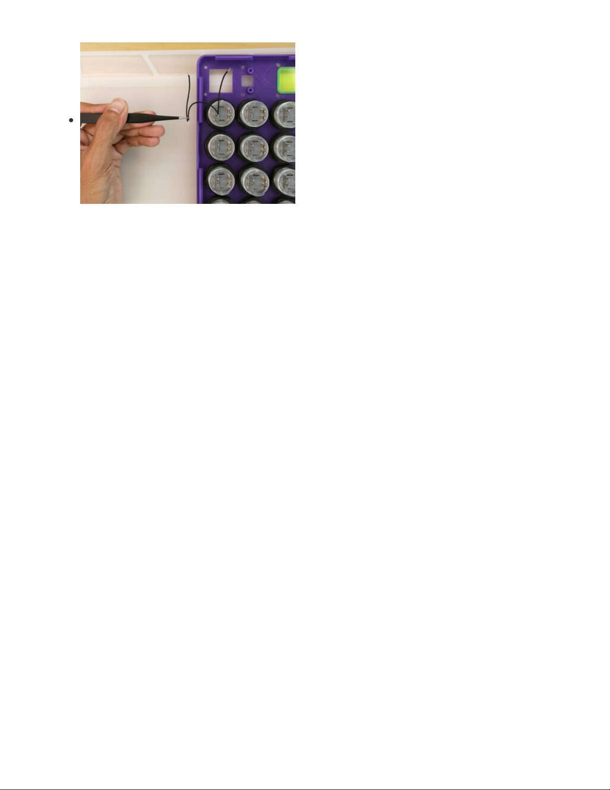
Sharing Ground
Each ground connect will need to jump to the next button in
the arrangement. Using tweezers can help hold two wires in
place while soldering.
© Adafruit Industries https://learn.adafruit.com/raspberry-pi-pico-led-arcade-button-midi-controller-fighter Page 44 of 63
Page 45

Wiring Grounds
Starting with the first button from the top right, proceed to
wire from right to left to complete the first row of four buttons.
On the four button, jump to the next row with button #8 and
proceed to jump from left to right.
On the fifth button, jump to the next row with button #9 and
proceed to share ground from right to left.
On the twelfth button, jump to the last row with button #16.
Proceed to share ground from left to right.
© Adafruit Industries https://learn.adafruit.com/raspberry-pi-pico-led-arcade-button-midi-controller-fighter Page 45 of 63
Page 46

Button Switches Shared Ground
Take a moment to double check the wiring and ensure the all
of the solder joints are solid. Lightly tug on the wires to check
if they're secured.
LED and Switch Shared Ground
On button #13 in last row, connect the second ground wire to
the ground pin on the LED. Proceed to share ground to all of
the button LEDs.
© Adafruit Industries https://learn.adafruit.com/raspberry-pi-pico-led-arcade-button-midi-controller-fighter Page 46 of 63
Page 47

Button LED Ground Wiring
Complete the last row, Button #13 to #16 and connect each
going right to left.
Proceed to connect Button #16 to Button #12 going from left
to right.
Proceed to connect Button #9 to Button #5 going from right
to left.
Proceed to connect Button #8 to Button #4 going from left to
right.
The last ground wire connects Button #2 to Button #1.
Once complete, take a moment to review all of the wires.
© Adafruit Industries https://learn.adafruit.com/raspberry-pi-pico-led-arcade-button-midi-controller-fighter Page 47 of 63
Page 48

Wiring Button Switches
Wire Planning
Start planning to wire the switches from all sixteen buttons to
the Raspberry Pi Pico. The wires will be soldered to the
bottom of the PCB.
Place the Raspberry Pi Pico over the opening in the top cover
to reference how long the wires will need to be in order to
reach the PCB.
Wires for Switches
Each wire will most likely have a different length of wire. To
help keep them organized, use heat shrink tubing, tape or
similar to keep sets of wire bundled together.
Here I've created four sets of wires, each set having four
wires.
Wiring Buttons 1-4
Solder the wires to buttons 1-4.
© Adafruit Industries https://learn.adafruit.com/raspberry-pi-pico-led-arcade-button-midi-controller-fighter Page 48 of 63
Page 49

Wiring Buttons 5-8
Solder the next set of wires to Buttons 5-8
Wiring Buttons 9-12
Solder the next set of wires to Buttons 9-12.
Wiring Buttons 13-16
Solder the last set of wires to Buttons 13-16.
Once complete, take a moment to review each wire.
© Adafruit Industries https://learn.adafruit.com/raspberry-pi-pico-led-arcade-button-midi-controller-fighter Page 49 of 63
Page 50

Wiring Button LEDs
Wires for LEDs
Time to make wires for connecting the Button LEDs. Create
four sets of wire, each set containing four wires.
Wiring LEDs 1-4
Proceed to wire up the LEDs in the first row.
Wiring LEDs 5-8
Proceed to wire up the second row, Buttons 5-8.
© Adafruit Industries https://learn.adafruit.com/raspberry-pi-pico-led-arcade-button-midi-controller-fighter Page 50 of 63
Page 51

Wiring LEDs 9-12
Proceed to wire up the third row, buttons 9-12.
Wiring LEDs 13-16
Proceed to wire up the last row, buttons 13-16.
Once complete, review.
© Adafruit Industries https://learn.adafruit.com/raspberry-pi-pico-led-arcade-button-midi-controller-fighter Page 51 of 63
Page 52

Wiring Button Switches to Pico
Wiring Button LEDs and Switches to Pico
Get ready to solder all of the wires to the bottom of the
Raspberry Pi Pico PCB.
Solder Button Switches 1-4
Use a PCB vise or third helping hands to keep the Raspberry
Pi Pico PCB secured while soldering.
Solder the switch wires from Button 1-4 to GP7-10.
Button 1 – GP7
Button 2 – GP8
Button 3 – GP9
Button 4 – GP10
Solder Button Switches 5-8
Proceed to wire up the second row of button switches to the
Raspberry Pi Pico.
Button 5 – GP11
Button 6 – GP12
Button 7 – GP13
Button 8 – GP14
Do not use GP15 – It's used as the boot select button and should be avoided.
© Adafruit Industries https://learn.adafruit.com/raspberry-pi-pico-led-arcade-button-midi-controller-fighter Page 52 of 63
Page 53

Solder Button Switches to 9-12
Proceed to wire up the third row of button switches to the
Raspberry Pi Pico.
Button 9 – GP16
Button 10 – GP17
Button 11 – GP18
Button 12 – GP19
Solder Button Switches 13-16
Proceed to wire up the last row of button switches to the
Raspberry Pi Pico.
Button 13 – GP20
Button 14 – GP21
Button 15 – GP22
Button 16 – GP26
© Adafruit Industries https://learn.adafruit.com/raspberry-pi-pico-led-arcade-button-midi-controller-fighter Page 53 of 63
Page 54

Install OLED
Solder Ground to OLED
Secure the OLED to a panavise, PCB vise or third helping
hands. Solder the remaining ground wire to the ground pin
on the OLED breakout.
Connect STEMMA Cables to OLED
Plug in the STEMMA QT cable from the Raspberry Pi Pico to
the left port on the side of the OLED.
Plug in the STEMMA QT / Qwiic JST SH 4-Pin Cable to the
right port on the other side of the OLED.
Hardware for OLED
Use the following hardware to secure the OLED to the top
cover.
4x M2.5 x 12mm screws
4x M2.5 hex nuts
© Adafruit Industries https://learn.adafruit.com/raspberry-pi-pico-led-arcade-button-midi-controller-fighter Page 54 of 63
Page 55

Install OLED to Top Cover
Place the OLED face down into the top cover. Line up the
mounting tabs with the mounting holes in the top cover.
Insert the screws through the holes in the top cover and push
them through the mounting holes on the OLED.
Secure OLED
While holding screw in place, insert and fasten an M2.5 hex
nut onto the thread of the screw. Tightly fasten to secure.
Proceed to install the remaining screws.
© Adafruit Industries https://learn.adafruit.com/raspberry-pi-pico-led-arcade-button-midi-controller-fighter Page 55 of 63
Page 56

Install 5-Way Nav Switch
Install Rubber Nub for 5-Way Nav Switch
Before panel mounting the 5-way navigation switch, install
the rubber nubbin for the Joystick (if you'd like, it's optional). It
is press fitted over the stem of the joystick and has a snug fit.
Screws for 5-Way Nav Switch
Install the 5-way navigation switch into the top cover. Line up
the mounting tabes with the built-in standoffs on the top
cover. Use the following screws to secure the 5-way
navigation switch.
2x M3 x 4mm screws
Secure 5-Way Nav Switch
Insert and fasten the two M3 x 4mm screws through the
mounting tabs on the PCBs.
© Adafruit Industries https://learn.adafruit.com/raspberry-pi-pico-led-arcade-button-midi-controller-fighter Page 56 of 63
Page 57

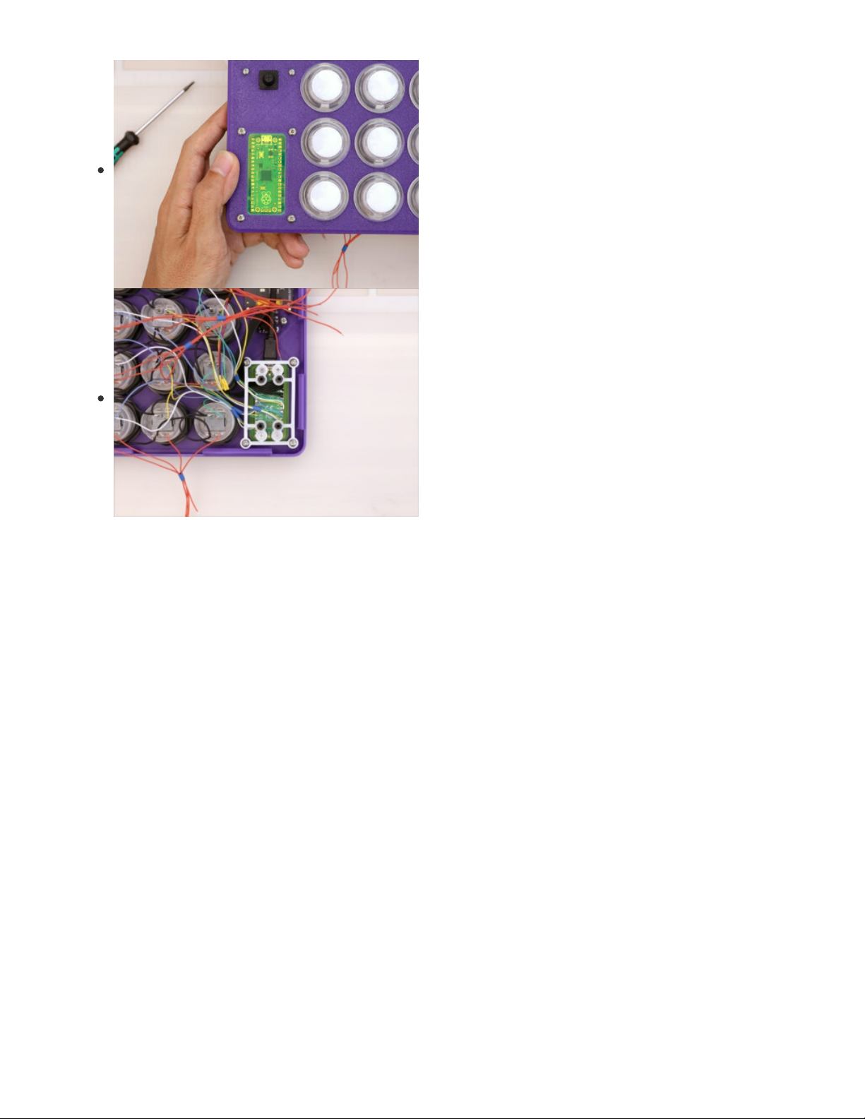
Install PCB Mount
Installing PCB Mount
Get the PCB mount ready to secure the Raspberry Pi Pico.
Use the following screws.
4x M2 x 4mm long screws
Secure Pico to PCB Mount
Carefully place the Raspberry Pi Pico over the M2 standoffs
that are secured to the PCB mount. Use the 4x M2 x 4mm
long screws to secure the Raspberry Pi Pico to the four M2
standoffs.
Connect USB Extension Cable to Pico
Grab the USB extension cable and connect it to the microUSB
port on the Raspberry Pi Pico. It's important to connect these
together before securing the PCB mount to the top cover.
Screws for Securing PCB mount to Top
Cover
Use the following screws to secure the PCB mount to the top
cover.
4x M3 x 4mm long screws
Secure PCB Mount to Top Cover
Position the PCB mount in place and line up the M3 standoffs
with the mounting holes in the top cover.
While holding in place, insert and fasten the 4x M3x4mm long
screws to secure the PCB mount to the top cover.
© Adafruit Industries https://learn.adafruit.com/raspberry-pi-pico-led-arcade-button-midi-controller-fighter Page 57 of 63
Page 58
Secured PCB Mount
Check the PCB mount is properly secured to the top cover.
© Adafruit Industries https://learn.adafruit.com/raspberry-pi-pico-led-arcade-button-midi-controller-fighter Page 58 of 63
Page 59

Install and Wire LED Driver
Screws for LED Driver
Use the following hardware to secure the LED driver to the
PCB mount.
4x M2.5 x 4mm long screws
Secure LED Driver to PCB Mount
Place the LED driver over the remaining M2.5 standoffs.
Insert and fasten 4x M2.5x4mm long screws to secure the
LED driver to the PCB mount.
Wire Button LEDs 1-4 to LED Driver
Get ready to solder the LED wires to the LED driver. Make the
following connections.
Button 1 – Pin #0
Button 2 – Pin #1
Button 3 – Pin #2
Button 4 – Pin #3
Note: Be careful not to miss Pin 0 – It's on the other side of the board.
© Adafruit Industries https://learn.adafruit.com/raspberry-pi-pico-led-arcade-button-midi-controller-fighter Page 59 of 63
Page 60

Wire Button LEDs 5-8 to LED Driver
Make the following connections.
Button 5 – Pin #4
Button 6 – Pin #5
Button 7 – Pin #6
Button 8 – Pin #7
Wire Button LEDs 9-12 to LED
Driver
Make the following connections.
Button 9 – Pin #8
Button 10 – Pin #9
Button 11 – Pin #10
Button 12 – Pin #11
Pins #8-11 are on the other side of the board.
Wire Button LEDs 13-16 to LED Driver
Make the following connections
Button 13 – Pin #12
Button 14 – Pin #13
Button 15 – Pin #14
Button 16 – Pin #15
© Adafruit Industries https://learn.adafruit.com/raspberry-pi-pico-led-arcade-button-midi-controller-fighter Page 60 of 63
Page 61

Connect STEMMA Cable to LED Driver
Lastly, connect the STEMMA cable from the OLED to the
STEMMA port on the LED driver.
It just plugs in, isn't STEMMA QT awesome?
Wiring Complete
YES! Congratulations, you've completed the wiring. Take a moment to bask in the glory.
© Adafruit Industries https://learn.adafruit.com/raspberry-pi-pico-led-arcade-button-midi-controller-fighter Page 61 of 63
Page 62

Final Assembly
Secure USB Extension Cable
The USB extension cable is panel mounted to the side of the
frame. Use the screws included or use your own (mine are
coated in black paint).
M3 x 10mm long screws
Hold the USB extension port in place with your desired
orientation. Insert and fasten the two M3 screws while
holding the USB port in place.
The stock length of the USB extension cable is just the right
length we need – No need to cut or extend, yay!
Close Case
The top cover snap fits onto the frame. Bring the two together
and line up the clips with the edges of the frame. Firmly press
them together to snap fit the case shut.
Final Build
And there you have it! Your DIY MIDI Controller is assembled
and ready for jamming. Congratulations!
© Adafruit Industries https://learn.adafruit.com/raspberry-pi-pico-led-arcade-button-midi-controller-fighter Page 62 of 63
Page 63

Jam Out
With your Raspberry Pi Pico MIDI controller all assembled, you're ready to jam! You can use it with any
software that allows MIDI input. Most commonly, you'll use a MIDI controller with music production
software such as Reason, Garage Band, FL Studio, Ableton Live, etc.
You could use the MIDI device for recording your own music with MIDI or for playing live. With the MIDI
mapping, you can create unique arrangements on the fly without having to go back and forth between
software and the device. In a live situation, the added control of the quick mapping opens up a world of
possibilities.
© Adafruit Industries Last Updated: 2021-04-15 10:02:00 AM EDT Page 63 of 63
 Loading...