

Page 1

CircuitPython on Linux and Raspberry Pi
Created by lady ada
Last updated on 2021-05-01 09:02:28 PM EDT
Page 2

2
4
4
4
6
6
6
7
8
8
8
10
10
10
12
12
17
17
18
19
19
22
23
23
26
28
29
29
33
33
34
37
37
41
41
44
44
47
47
47
47
48
48
49
50
Guide Contents
Guide Contents
Overview
Why CircuitPython?
CircuitPython on Microcontrollers
CircuitPython & RasPi
CircuitPython Libraries on Linux & Raspberry Pi
Wait, isn't there already something that does this - GPIO Zero?
What about other Linux SBCs?
Installing CircuitPython Libraries on Raspberry Pi
Prerequisite Pi Setup!
Update Your Pi and Python
Check I2C and SPI
Enabling Second SPI
Blinka Test
Digital I/O
Parts Used
Wiring
Blinky Time!
Button It Up
I2C Sensors & Devices
Parts Used
Wiring
Install the CircuitPython BME280 Library
Run that code!
I2C Clock Stretching
SPI Sensors & Devices
Using the Second SPI Port
Parts Used
Wiring
Install the CircuitPython MAX31855 Library
Run that code!
UART / Serial
The Easy Way - An External USB-Serial Converter
The Hard Way - Using Built-in UART
Disabling Console & Enabling Serial
Install the CircuitPython GPS Library
Run that code!
PWM Outputs & Servos
Update Adafruit Blinka
Supported Pins
PWM - LEDs
Servo Control
pulseio Servo Control
adafruit_motor Servo Control
More To Come!
© Adafruit Industries https://learn.adafruit.com/circuitpython-on-raspberrypi-linux Page 2 of 59
Page 3

51
52
52
52
52
52
53
53
54
54
54
54
CircuitPython & OrangePi
FAQ & Troubleshooting
Update Blinka/Platform Libraries
Getting an error message about "board" not found or "board" has no attribute
Mixed SPI mode devices
Why am I getting AttributeError: 'SpiDev' object has no attribute 'writebytes2'?
No Pullup/Pulldown support on some linux boards or MCP2221
Getting OSError: read error with MCP2221
Using FT232H with other FTDI devices.
I can't get neopixel, analogio, audioio, rotaryio, displayio or pulseio to work!
Help, I'm getting the message "error while loading shared libraries: libgpiod.so.2: cannot open shared object file:
No such file or directory"
When running the libgpiod script, I see the message: configure: error: "libgpiod needs linux headers version
>= v5.5.0"
© Adafruit Industries https://learn.adafruit.com/circuitpython-on-raspberrypi-linux Page 3 of 59
Page 4

Overview
Please note! All the stuff in this guide works and we're improving and working on this code a bunch
so be sure to check back for updates!
Here at Adafruit we're always looking for ways to make
making easier
- whether that's making breakout
boards for hard-to-solder sensors or writing libraries to simplify motor control. Our new favorite way to
program is CircuitPython.
Why CircuitPython?
CircuitPython is a variant of MicroPython, a very small version of Python that can fit on a microcontroller.
Python is the fastest-growing programming language. It's taught in schools, used in coding bootcamps,
popular with scientists and of course programmers at companies use it a lot!
CircuitPython adds the Circuit part to the Python part. Letting you program in Python and talk to Circuitry
like sensors, motors, and LEDs!
CircuitPython on Microcontrollers
For a couple years now we've had CircuitPython for microcontrollers like our SAMD21 series with
Feather/Trinket/CircuitPlayground/Metro M0, as well as the ESP8266 WiFi microcontroller, nRF52
bluetooth microcontroller and SAMD51 series.
All of these chips have something in common - they are
microcontrollers
with hardware peripherals like
SPI, I2C, ADCs etc. We squeeze Python into 'em and can then make the project portable.
But...sometimes you want to do more than a microcontroller can do. Like HDMI video output, or camera
capture, or serving up a website, or just something that takes more memory and computing than a
microcontroller board can do...
© Adafruit Industries https://learn.adafruit.com/circuitpython-on-raspberrypi-linux Page 4 of 59
Page 5

© Adafruit Industries https://learn.adafruit.com/circuitpython-on-raspberrypi-linux Page 5 of 59
Page 6

CircuitPython & RasPi
CircuitPython Libraries on Linux & Raspberry Pi
The next obvious step is to bring CircuitPython back to 'desktop Python'. We've got tons of projects,
libraries and example code for CircuitPython on microcontrollers, and thanks to the flexibility and power of
Python it's pretty easy to get that code working with micro-computers like Raspberry Pi or other 'Linux with
GPIO pins available' single board computers.
We are not running the CircuitPython interpreter itself on the Linux machine. But we
are
running Python
code written to use the CircuitPython hardware API ( busio.I2C , busio.SPI , etc.)
We'll use a special library called adafruit_blinka (https://adafru.it/BJS) (named after Blinka, the
CircuitPython mascot (https://adafru.it/BJT)) to provide the layer that translates the CircuitPython hardware
API to whatever library the Linux board provides. For example, on Raspberry Pi we use the python
RPi.GPIO (https://adafru.it/BJU) library. For any I2C interfacing we'll use ioctl messages to the /dev/i2c
device. For SPI we'll use the spidev python library, etc. These details don't matter so much because they
all happen underneath the adafruit_blinka layer.
The upshot is that any code we have for CircuitPython will be instantly and easily runnable on Linux
computers like Raspberry Pi.
In particular
, we'll be able to use all of our device drivers - the sensors, led controllers, motor drivers,
HATs, bonnets, etc. And nearly all of these use I2C or SPI!
Wait, isn't there already something that does this - GPIO Zero?
Yes! We like and use GPIO Zero a lot (https://adafru.it/BJV), its an excellent hardware interfacing library for
Raspberry Pi. It's great for digital in/out, analog inputs, servos, some basic sensors, etc. In particular, one
cool thing it does is thread/event management so you can have code run, say, when a button is pressed.
© Adafruit Industries https://learn.adafruit.com/circuitpython-on-raspberrypi-linux Page 6 of 59
Page 7

GPIO Zero excels at that, but doesn't cover SPI/I2C sensors or drivers, which is where we got stuck: for
each sensor we had we'd write a driver in C/C++ for Arduino, CircuitPython using our hardware API, and
then Python using smbus or similar.
By letting you use CircuitPython on Raspberry Pi via adafruit_blinka, you can unlock all of the drivers and
example code we wrote!
And
you can keep using GPIO Zero for pins, buttons and LEDs. We save time and
effort so we can focus on getting code that works in one place, and you get to reuse all the code we've
written already.
What about other Linux SBCs?
Plus, we're adapting and extending adafruit_blinka to support
other
boards (https://adafru.it/DbB) such as
Allwinners and BeagleBone, even some smaller linux boards like Onion.io will be able to run CircuitPython
code.
If you have a board you'd like to adapt check out the adafruit_blinka code on github (https://adafru.it/BJX),
pull requests are welcome as there's a
ton
of different Linux boards out there! You'll need to add a
detection element (https://adafru.it/Dyb) so we can tell what board you're running on, then the pin
definitions into adafruit_blinka above. As long as you're running a modern kernel, you'll have libgpiod for
GPIO, smbus for I2C and spidev for SPI all ready to go.
© Adafruit Industries https://learn.adafruit.com/circuitpython-on-raspberrypi-linux Page 7 of 59
Page 8

Installing CircuitPython Libraries on Raspberry Pi
CircuitPython libraries and adafruit-blinka will work on any Raspberry Pi board! That means the
original 1, the Pi 2, Pi 3, Pi 4, Pi Zero, or even the compute module.
At this time, Blinka requires Python version 3.6 or later, which means you will need to at least be
running Raspberry Pi OS Buster.
Prerequisite Pi Setup!
In this page we'll assume you've already gotten your Raspberry Pi up and running and can log into the
command line
Here's the quick-start for people with some experience:
1. Download the latest Raspberry Pi OS or Raspberry Pi OS Lite (https://adafru.it/Pf5) to your computer
2. Burn the OS image to your MicroSD card (https://adafru.it/dDL) using your computer
3. Re-plug the SD card into your computer (don't use your Pi yet!) and set up your wifi connection by
editing supplicant.conf (https://adafru.it/yuD)
4. Activate SSH support (https://adafru.it/yuD)
5. Plug the SD card into the Pi
6. If you have an HDMI monitor we recommend connecting it so you can see that the Pi is booting OK
7. Plug in power to the Pi - you will see the green LED flicker a little. The Pi will reboot while it sets up
so wait a good 10 minutes
8. If you are running Windows on your computer, install Bonjour support so you can use .local names,
you'll need to reboot Windows after installation (https://adafru.it/lPE)
9. You can then ssh into raspberrypi.local (https://adafru.it/jvB)
The Pi Foundation has tons of guides as well (https://adafru.it/BJY)
We really really recommend the lastest Raspberry Pi OS only. If you have an older Raspberry Pi OS
install, run "sudo apt-get update" and "sudo apt-get upgrade" to get the latest OS!
Update Your Pi and Python
Run the standard updates:
sudo apt-get update
sudo apt-get upgrade
sudo apt-get install python3-pip
and
sudo pip3 install --upgrade setuptools
© Adafruit Industries https://learn.adafruit.com/circuitpython-on-raspberrypi-linux Page 8 of 59
Page 9

Python2 support has been dropped, so you will need to either use pip3 and python3 as commands
or set Python 3 as the default python install.
We put together a script to easily make sure your Pi is correctly configured and install Blinka. It requires
just a few commands to run. Most of it is installing the dependencies.
cd ~
sudo pip3 install --upgrade adafruit-python-shell
wget https://raw.githubusercontent.com/adafruit/Raspberry-Pi-Installer-Scripts/master/raspi-blinka.py
sudo python3 raspi-blinka.py
If your system default Python is Python 2 (which is likely on a
first install), it will ask to confirm that you want to proceed.
Choose yes.
It may take a few minutes to run. When it finishes, it will ask
you if you would like to reboot. Choose yes.
Once it reboots, the connection will close. After a couple of
minutes, you can reconnect.
© Adafruit Industries https://learn.adafruit.com/circuitpython-on-raspberrypi-linux Page 9 of 59
Page 10
Check I2C and SPI
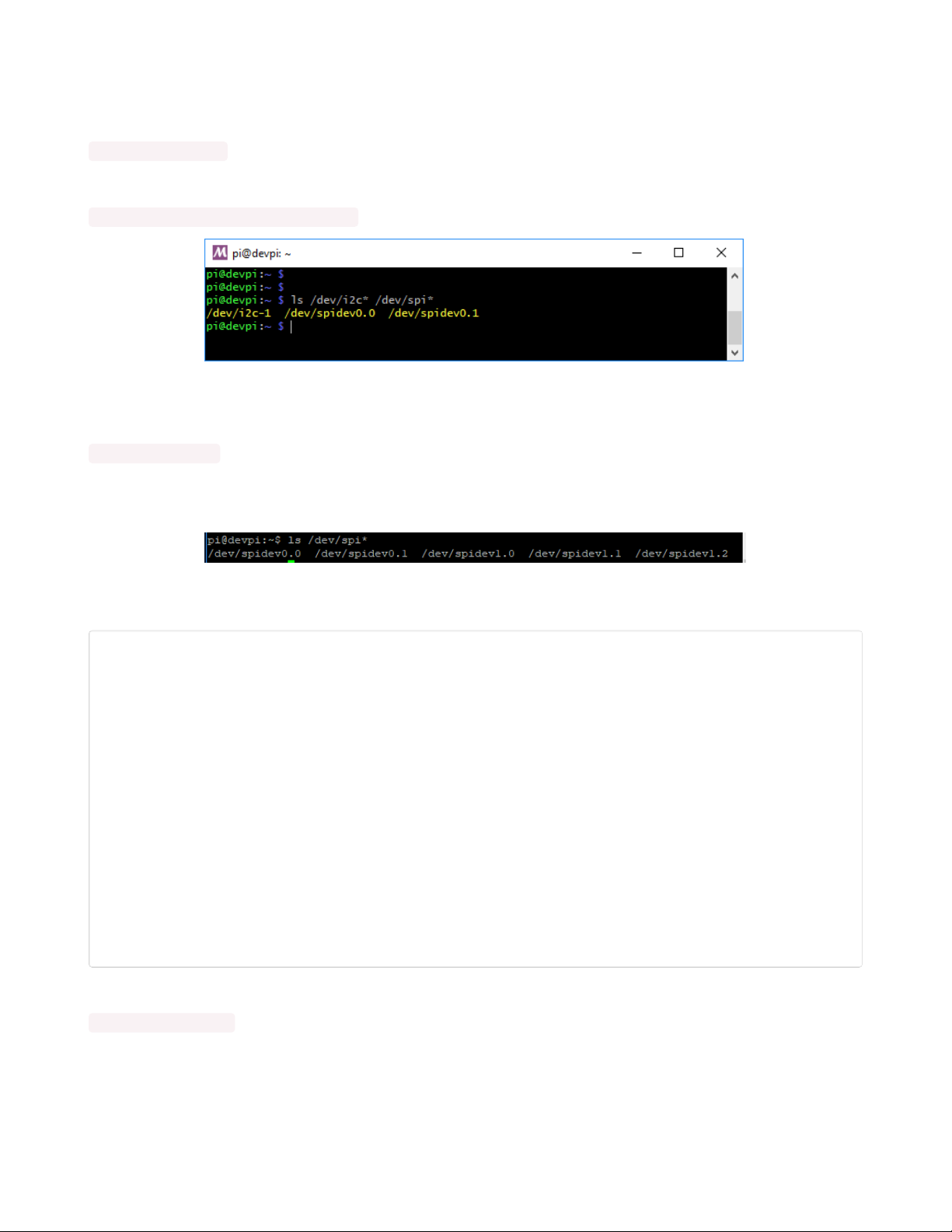
The script will automatically enable I2C and SPI. You can run the following command to verify:
ls /dev/i2c* /dev/spi*
You should see the response
/dev/i2c-1 /dev/spidev0.0 /dev/spidev0.1
Enabling Second SPI
If you are using the main SPI port for a display or something and need another hardware SPI port, you can
enable it by adding the line
dtoverlay=spi1-3cs
to the bottom of /boot/config.txt and rebooting. You'll then see the addition of some /dev/spidev1.x
devices:
Blinka Test
Create a new file called blinkatest.py with nano or your favorite text editor and put the following in:
import board
import digitalio
import busio
print("Hello blinka!")
# Try to great a Digital input
pin = digitalio.DigitalInOut(board.D4)
print("Digital IO ok!")
# Try to create an I2C device
i2c = busio.I2C(board.SCL, board.SDA)
print("I2C ok!")
# Try to create an SPI device
spi = busio.SPI(board.SCLK, board.MOSI, board.MISO)
print("SPI ok!")
print("done!")
Save it and run at the command line with
python3 blinkatest.py
You should see the following, indicating digital i/o, I2C and SPI all worked
© Adafruit Industries https://learn.adafruit.com/circuitpython-on-raspberrypi-linux Page 10 of 59
Page 11

© Adafruit Industries https://learn.adafruit.com/circuitpython-on-raspberrypi-linux Page 11 of 59
Page 12

Digital I/O
The first step with any new hardware is the 'hello world' of electronics - blinking an LED. This is very easy
with CircuitPython and Raspberry Pi. We'll extend the example to also show how to wire up a
button/switch and enable a pull-up resistor.
Even if you use a different library to create digital in/outs like GPIO Zero, there's a number of sensor
libraries that use a digital pin for resetting, or for a chip-select. So it's good to have this part working!
Parts Used
Any old LED will work just fine as long as its not an IR LED (you can't see those) and a 470 to 2.2K resistor
Diffused Blue 10mm LED (25 pack)
Need some big indicators? We are big fans of these huge diffused blue LEDs. They are really bright so
they can be seen in daytime, and from any angle. They go easily into a breadboard...
$9.95
In Stock
Add to Cart
© Adafruit Industries https://learn.adafruit.com/circuitpython-on-raspberrypi-linux Page 12 of 59
Page 13

Through-Hole Resistors - 470 ohm 5% 1/4W - Pack of 25
ΩMG! You're not going to be able to resist these handy resistor packs! Well, axially, they do all of the
resisting for you!This is a 25 Pack of...
Out of Stock
Some tactile buttons or switches
Out of
Stock
© Adafruit Industries https://learn.adafruit.com/circuitpython-on-raspberrypi-linux Page 13 of 59
Page 14

Tactile Switch Buttons (12mm square, 6mm tall) x 10 pack
Medium-sized clicky momentary switches are standard input "buttons" on electronic projects. These work
best in a PCB but
$2.50
In Stock
We recommend using a breadboard and some female-male wires.
Add to Cart
© Adafruit Industries https://learn.adafruit.com/circuitpython-on-raspberrypi-linux Page 14 of 59
Page 15

Premium Female/Male 'Extension' Jumper Wires - 40 x 6" (150mm)
Handy for making wire harnesses or jumpering between headers on PCB's. These premium jumper wires
are 6" (150mm) long and come in a 'strip' of 40 (4 pieces of each of ten rainbow...
$3.95
In Stock
You can use a Cobbler to make this a little easier, the pins are then labeled!
Add to Cart
© Adafruit Industries https://learn.adafruit.com/circuitpython-on-raspberrypi-linux Page 15 of 59
Page 16

Adafruit Pi Cobbler + Kit- Breakout Cable for Pi B+/A+/Pi 2/Pi 3
The Raspberry Pi B+ has landed on the Maker World like a 40-GPIO pinned, quad-USB ported, credit card
sized bomb of DIY joy. And while you can use most of our great Model B accessories...
Out of Stock
Out of
Stock
© Adafruit Industries https://learn.adafruit.com/circuitpython-on-raspberrypi-linux Page 16 of 59
Page 17

Assembled Pi T-Cobbler Plus - GPIO Breakout
This is the assembled version of the Pi T-Cobbler Plus. It only works with the Raspberry Pi Model Zero,
A+, B+, Pi 2, Pi 3 & Pi 4! (Any Pi with 2x20...
$7.95
In Stock
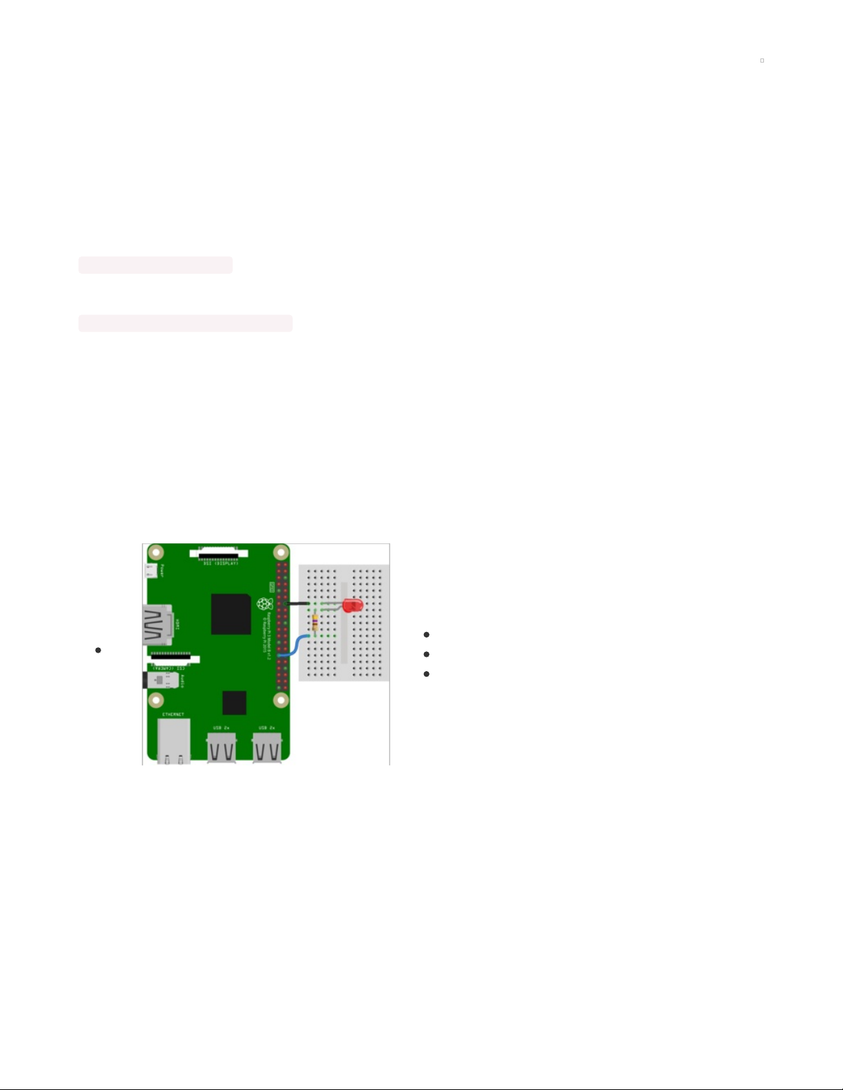
Wiring
Connect the Raspberry Pi Ground pin to the blue ground rail on the breadboard.
Connect one side of the tactile switch to Raspberry Pi GPIO #4
Connect the other side of the tactile switch to the ground rail
Connect the longer/positive pin of the LED to Raspberry Pi GPIO #18
Connect the shorter/negative pin of the LED to a 470ohm to 2.2K resistor, the other side of the
resistor goes to ground rail
Double-check you have the right wires connected to the right location, it can be tough to keep track of Pi
pins as there are forty of them!
No additional libraries are needed so we can go straight on to the example code
However, we recommend running a pip3 update!
pip3 install --upgrade adafruit_blinka
Blinky Time!
The finish line is right up ahead, lets start with an example that blinks the LED on and off once a second
(half a second on, half a second off):
Add to Cart
© Adafruit Industries https://learn.adafruit.com/circuitpython-on-raspberrypi-linux Page 17 of 59
Page 18

import time
import board
import digitalio
print("hello blinky!")
led = digitalio.DigitalInOut(board.D18)
led.direction = digitalio.Direction.OUTPUT
while True:
led.value = True
time.sleep(0.5)
led.value = False
time.sleep(0.5)
Verify the LED is blinking. If not, check that it's wired to GPIO #18, the resistor is installed correctly, and
you have a Ground wire to the Raspberry Pi.
Type Control-C to quit
Button It Up
Now that you have the LED working, lets add code so the LED turns on whenever the button is pressed
import time
import board
import digitalio
print("press the button!")
led = digitalio.DigitalInOut(board.D18)
led.direction = digitalio.Direction.OUTPUT
button = digitalio.DigitalInOut(board.D4)
button.direction = digitalio.Direction.INPUT
button.pull = digitalio.Pull.UP
while True:
led.value = not button.value # light when button is pressed!
Press the button - see that the LED lights up!
Type Control-C to quit
© Adafruit Industries https://learn.adafruit.com/circuitpython-on-raspberrypi-linux Page 18 of 59
Page 19

I2C Sensors & Devices
The most popular electronic sensors use
I2C
to communicate. This is a 'shared bus' 2 wire protocol, you
can have multiple sensors connected to the two SDA and SCL pins as long as they have unique addresses
(check this guide for a list of many popular devices and their addresses (https://adafru.it/BK0))
Lets show how to wire up a popular BME280. This sensor provides temperature, barometric pressure and
humidity data over I2C
We're going to do this in a lot more depth than our guide pages for each sensor, but the overall technique
is basically identical for any and all I2C sensors.
Honestly, the hardest part of using I2C devices is figuring out the I2C address (https://adafru.it/BK0) and
which pin is SDA and which pin is SCL!
Don't forget you have to enable I2C with raspi-config!
Parts Used
Adafruit BME280 I2C or SPI Temperature Humidity Pressure Sensor
Bosch has stepped up their game with their new BME280 sensor, an environmental sensor with
temperature, barometric pressure and humidity! This sensor is great for all sorts...
$14.95
In Stock
We recommend using a breadboard and some female-male wires.
Add to Cart
© Adafruit Industries https://learn.adafruit.com/circuitpython-on-raspberrypi-linux Page 19 of 59
Page 20

Premium Female/Male 'Extension' Jumper Wires - 40 x 6" (150mm)
Handy for making wire harnesses or jumpering between headers on PCB's. These premium jumper wires
are 6" (150mm) long and come in a 'strip' of 40 (4 pieces of each of ten rainbow...
$3.95
In Stock
You can use a Cobbler to make this a little easier, the pins are then labeled!
Add to Cart
© Adafruit Industries https://learn.adafruit.com/circuitpython-on-raspberrypi-linux Page 20 of 59
Page 21

Adafruit Pi Cobbler + Kit- Breakout Cable for Pi B+/A+/Pi 2/Pi 3
The Raspberry Pi B+ has landed on the Maker World like a 40-GPIO pinned, quad-USB ported, credit card
sized bomb of DIY joy. And while you can use most of our great Model B accessories...
Out of Stock
Out of
Stock
© Adafruit Industries https://learn.adafruit.com/circuitpython-on-raspberrypi-linux Page 21 of 59
Page 22

Assembled Pi T-Cobbler Plus - GPIO Breakout
This is the assembled version of the Pi T-Cobbler Plus. It only works with the Raspberry Pi Model Zero,
A+, B+, Pi 2, Pi 3 & Pi 4! (Any Pi with 2x20...
$7.95
In Stock
Wiring
Connect the Raspberry Pi 3.3V power pin to Vin
Connect the Raspberry Pi GND pin to GND
Connect the Pi SDA pin to the BME280 SDI
Connect the Pi SCL pin to to the BME280 SCK
Double-check you have the right wires connected to the right location, it can be tough to keep track of Pi
pins as there are forty of them!
After wiring, we recommend running I2C detection to verify that you see the device, in this case its
address 77
sudo i2cdetect -y 1
Add to Cart
© Adafruit Industries https://learn.adafruit.com/circuitpython-on-raspberrypi-linux Page 22 of 59
Page 23

Install the CircuitPython BME280 Library
OK onto the good stuff, you can now install the Adafruit BME280 CircuitPython library.
As of this writing, not
all
libraries are up on PyPI so you may want to search before trying to install. Look
for circuitpython and then the driver you want.
(If you don't see it you can open up a github issue on circuitpython to remind us (https://adafru.it/tB7)!)
Once you know the name, install it with
pip3 install adafruit-circuitpython-bme280
You'll notice we also installed a
dependancy
called adafruit-circuitpython-busdevice. This is a great thing
about pip, if you have other required libraries they'll get installed too!
We also recommend an adafruit-blinka update in case we've fixed bugs:
pip3 install --upgrade adafruit_blinka
Run that code!
© Adafruit Industries https://learn.adafruit.com/circuitpython-on-raspberrypi-linux Page 23 of 59
Page 24

The finish line is right up ahead. You can now run one of the (many in some cases) example scripts we've
written for you.
Check out the examples for your library by visiting the repository for the library and looking in the example
folder. In this case, it would be
https://github.com/adafruit/Adafruit_CircuitPython_BME280/tree/master/examples (https://adafru.it/BK1)
As of this writing there's only one example. But that's cool, here it is:
# SPDX-FileCopyrightText: 2021 ladyada for Adafruit Industries
# SPDX-License-Identifier: MIT
import time
import board
import adafruit_bme280
# Create sensor object, using the board's default I2C bus.
i2c = board.I2C() # uses board.SCL and board.SDA
bme280 = adafruit_bme280.Adafruit_BME280_I2C(i2c)
# OR create sensor object, using the board's default SPI bus.
# spi = board.SPI()
# bme_cs = digitalio.DigitalInOut(board.D10)
# bme280 = adafruit_bme280.Adafruit_BME280_SPI(spi, bme_cs)
# change this to match the location's pressure (hPa) at sea level
bme280.sea_level_pressure = 1013.25
while True:
print("\nTemperature: %0.1f C" % bme280.temperature)
print("Humidity: %0.1f %%" % bme280.relative_humidity)
print("Pressure: %0.1f hPa" % bme280.pressure)
print("Altitude = %0.2f meters" % bme280.altitude)
time.sleep(2)
Save this code to your Pi by copying and pasting it into a text file, downloading it directly from the Pi, etc.
Then in your command line run
python3 bme280_simpletest.py
The code will loop with the sensor data until you quit with a Control-C
That's it! Now if you want to read the documentation on the library, what each function does in depth, visit
© Adafruit Industries https://learn.adafruit.com/circuitpython-on-raspberrypi-linux Page 24 of 59
Page 25

our readthedocs documentation at
https://circuitpython.readthedocs.io/projects/bme280/en/latest/ (https://adafru.it/BK2)
© Adafruit Industries https://learn.adafruit.com/circuitpython-on-raspberrypi-linux Page 25 of 59
Page 26
I2C Clock Stretching
In order to use certain I2C sensors, such as the BNO055 (https://adafru.it/fE0), BNO085 and the
CCS811 (https://adafru.it/BlK), you'll need to enable I2C clock stretching 'support' by greatly slowing down
the I2C clock on the Raspberry Pi using the device tree overlay.
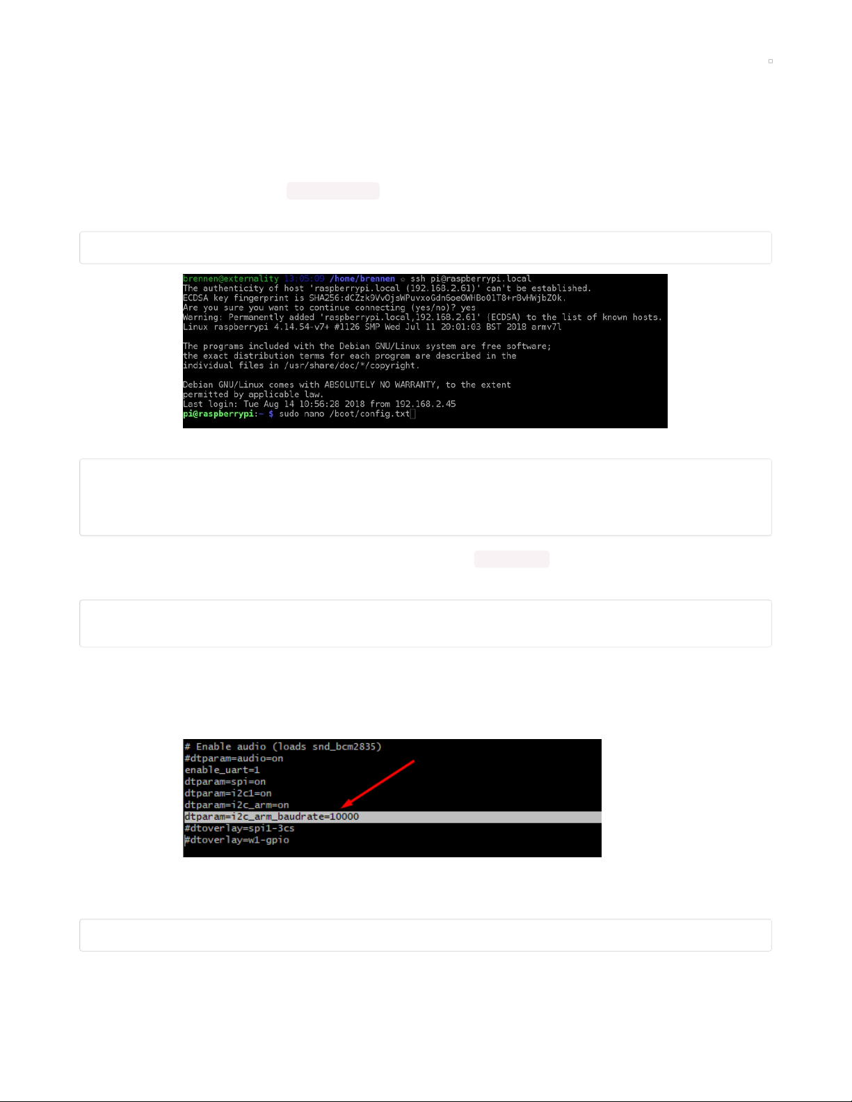
This is done by adding a line in /boot/config.txt . Log in to a terminal on your Pi and open that file in Nano,
or your text editor of choice:
sudo nano /boot/config.txt
Scroll down until you find a block like:
# Uncomment some of all of these to enable the optional hardware interfaces
dtparam=i2c_arm=on
dtparam=i2s=on
dtparam=spi=on
This block might vary depending on what you've enabled in raspi-config . Directly below it, add the
following:
# Clock stretching by slowing down to 10KHz
dtparam=i2c_arm_baudrate=10000
The default baudrate may be 100KHz or 1MHz, by slowing it down to 10KHz or more, you may be able to
be slow enough to avoid missing clocks.
In Nano, your screen should look like this:
Next, save the file and exit (in Nano, press Ctrl-X, y for yes, and Enter).
Now you can reboot your Pi and proceed to testing your I2C device:
sudo reboot
If you still get bad data, try slowing it down more, maybe to 5 KHz or 1 KHz rate. Reboot after each change
© Adafruit Industries https://learn.adafruit.com/circuitpython-on-raspberrypi-linux Page 26 of 59
Page 27

© Adafruit Industries https://learn.adafruit.com/circuitpython-on-raspberrypi-linux Page 27 of 59
Page 28

SPI Sensors & Devices
SPI is less popular than I2C but still you'll see lots of sensors and chips use it. Unlike I2C, you don't have
everything share two wires. Instead, there's three shared wires (clock, data in, data out) and then a unique
'chip select' line for each chip.
The nice thing about SPI is you can have as many chips as you like, even the same kind, all share the three
SPI wires, as long as each one has a unique chip select pin.
The formal/technical names for the 4 pins used are:
SPI clock - called SCLK, SCK or CLK
SPI data out - called MOSI for Microcomputer Out Serial In. This is the wire that takes data
from
the
Linux computer to the sensor/chip. Sometimes marked SDI or DI on chips
SPI data in - called MISO for Microcomputer In Serial Out. This is the wire that takes data to the Linux
computer
from
the sensor/chip. Sometimes marked SDO or DO on chips
SPI chip select - called CS or CE
Remember, connect all SCK, MOSI and MISO pins together (unless there's some specific
reason/instruction not to) and a unique CS pin for each device.
WARNING! SPI on Linux/Raspberry PI WARNING!
SPI on microcontrollers is fairly simple, you have an SPI peripheral and you can transfer data on it with
some low level command. Its 'your job' as a programmer to control the CS lines with a GPIO. That's how
CircuitPython is structured as well. busio does just the SPI transmit/receive part and busdevice handles
the chip select pin as well.
Linux, on the other hand, doesn't let you send data to SPI without a CS line, and the CS lines are fixed in
hardware as well. For example on the Raspberry Pi, there's only two CS pins available for the hardware SPI
pins - CE0 and CE1 - and you
have
to use them. (In theory there's an ioctl option called no_cs but this
does not actually work)
The upshot here is - to let you use more than 2 peripherals on SPI, we decided to let you use any CS pins
you like, CircuitPython will toggle it the way you expect. But when we transfer SPI data we always tell the
kernel to use CE0. CE0 will toggle like a CS pin, but if we leave it disconnected, its no big deal
The upshot here is basically never connect anything to CE0 (or CE1 for that matter). Use whatever chip
select pin you define in CircuitPython and just leave the CE pins alone, it will toggle as if it is the chip
select line, completely on its own, so you shouldn't try to use it as a digital input/output/whatever.
Don't forget you have to enable SPI with raspi-config!
If you have installed a PiTFT from another guide, you will need to "uninstall" that before you can use
the main spi ports.
© Adafruit Industries https://learn.adafruit.com/circuitpython-on-raspberrypi-linux Page 28 of 59
Page 29
Using the Second SPI Port
The Raspberry Pi has a 'main' SPI port, but not a lot of people know there's a second one too! This is
handy if you are using the main SPI port for a PiTFT or other kernel-driven device. You can enable this SPI
#1 by adding (https://adafru.it/Oaa)
dtoverlay=spi1-3cs
to the bottom of /boot/config.txt and rebooting. You'll then see the addition of some /dev/spidev1.x
devices.
Here's the wiring for SPI #1:
SCK_1 on GPIO #21
MOSI_1 on GPIO #20
MISO_1 on GPIO #19
SPI #1 CS0 on GPIO 18
SPI #1 CS1 on GPIO 17
SPI #1 CS2 on GPIO 16
like the main SPI, we'll use CE0 as our default but don't connect to it! Use any other pin and leave that one
unused. Then update your scripts to use
spi = busio.SPI(board.SCK_1, MOSI=board.MOSI_1, MISO=board.MISO_1)
Parts Used
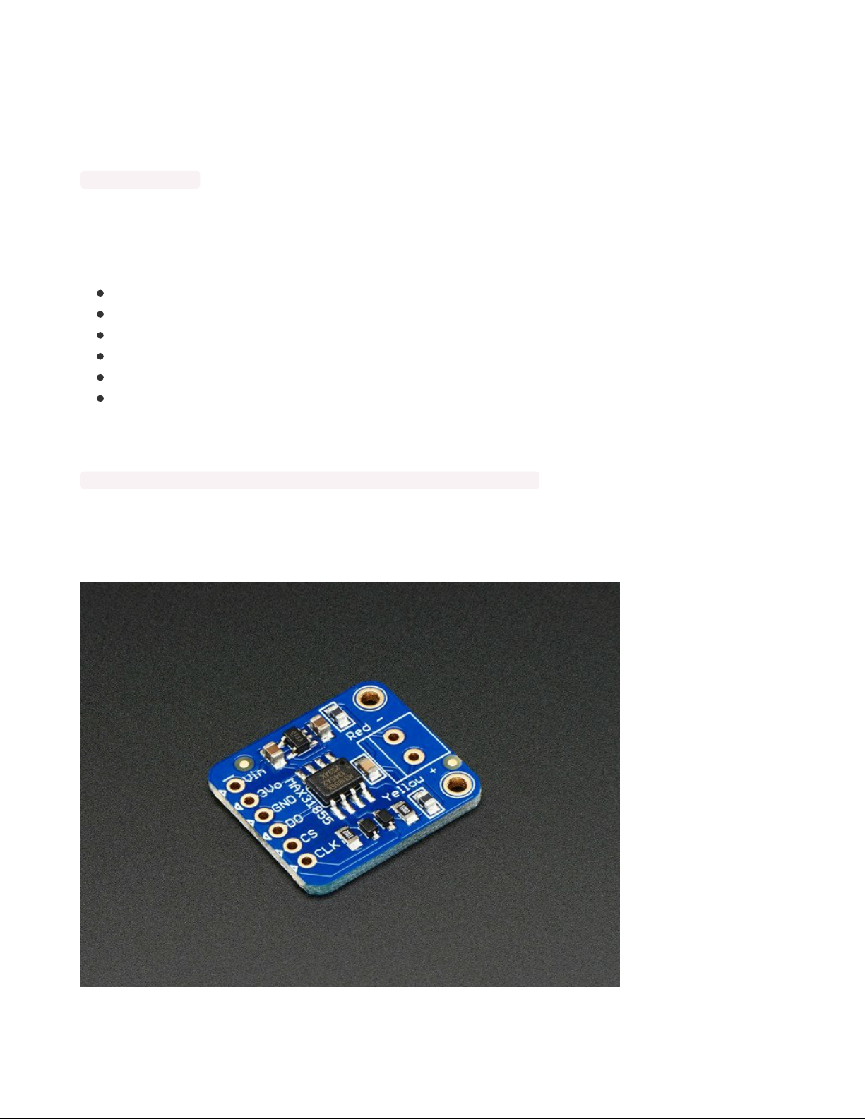
OK now that we've gone thru the warning, lets wire up an SPI MAX31855 thermocouple sensor, this
particular device doesn't have a MOSI pin so we'll not connect it.
Thermocouple Amplifier MAX31855 breakout board (MAX6675 upgrade)
© Adafruit Industries https://learn.adafruit.com/circuitpython-on-raspberrypi-linux Page 29 of 59
Page 30

Thermocouples are very sensitive, requiring a good amplifier with a cold-compensation reference. The
MAX31855K does everything for you, and can be easily interfaced with any...
$14.95
In Stock
Thermocouple Type-K Glass Braid Insulated
Thermocouples are best used for measuring temperatures that can go above 100 °C. This is a bare wires
bead-probe which can measure air or surface temperatures. Most inexpensive...
$9.95
In Stock
We recommend using a breadboard and some female-male wires.
Add to Cart
Add to Cart
© Adafruit Industries https://learn.adafruit.com/circuitpython-on-raspberrypi-linux Page 30 of 59
Page 31

Premium Female/Male 'Extension' Jumper Wires - 40 x 6" (150mm)
Handy for making wire harnesses or jumpering between headers on PCB's. These premium jumper wires
are 6" (150mm) long and come in a 'strip' of 40 (4 pieces of each of ten rainbow...
$3.95
In Stock
You can use a Cobbler to make this a little easier, the pins are then labeled!
Add to Cart
© Adafruit Industries https://learn.adafruit.com/circuitpython-on-raspberrypi-linux Page 31 of 59
Page 32

Adafruit Pi Cobbler + Kit- Breakout Cable for Pi B+/A+/Pi 2/Pi 3
The Raspberry Pi B+ has landed on the Maker World like a 40-GPIO pinned, quad-USB ported, credit card
sized bomb of DIY joy. And while you can use most of our great Model B accessories...
Out of Stock
Out of
Stock
© Adafruit Industries https://learn.adafruit.com/circuitpython-on-raspberrypi-linux Page 32 of 59
Page 33

Assembled Pi T-Cobbler Plus - GPIO Breakout
This is the assembled version of the Pi T-Cobbler Plus. It only works with the Raspberry Pi Model Zero,
A+, B+, Pi 2, Pi 3 & Pi 4! (Any Pi with 2x20...
$7.95
In Stock
Wiring
Connect the Raspberry Pi 3.3V power pin to Vin
Connect the Raspberry Pi GND pin to GND
Connect the Pi SCLK pin to the MAX31855 CLK
Connect the Pi MISO pin to to the MAX31855 DO
Connect the Pi GPIO 5 pin to to the MAX31855 CS
https://adafru.it/BKi
Double-check you have the right wires connected to the right location, it can be tough to keep track of Pi
pins as there are forty of them!
Install the CircuitPython MAX31855 Library
OK onto the good stuff, you can now install the Adafruit MAX31855 CircuitPython library.
As of this writing, not
all
libraries are up on PyPI so you may want to search before trying to install. Look
for circuitpython and then the driver you want.
Add to Cart
https://adafru.it/BKi
© Adafruit Industries https://learn.adafruit.com/circuitpython-on-raspberrypi-linux Page 33 of 59
Page 34

(If you don't see it you can open up a github issue on circuitpython to remind us (https://adafru.it/tB7)!)
Once you know the name, install it with
pip3 install adafruit-circuitpython-max31855
You'll notice we also installed a few other
dependancies
called spidev, adafruit-pureio, adafruit-
circuitpython-busdevice and more. This is a great thing about pip, if you have other required libraries
they'll get installed too!
We also recommend an adafruit-blinka update in case we've fixed bugs:
pip3 install --upgrade adafruit_blinka
Run that code!
The finish line is right up ahead. You can now run one of the (many in some cases) example scripts we've
written for you.
Check out the examples for your library by visiting the repository for the library and looking in the example
folder. In this case, it would be
https://github.com/adafruit/Adafruit_CircuitPython_MAX31855/tree/master/examples (https://adafru.it/BKj)
© Adafruit Industries https://learn.adafruit.com/circuitpython-on-raspberrypi-linux Page 34 of 59
Page 35

As of this writing there's only one example. But that's cool, here it is:
# SPDX-FileCopyrightText: 2021 ladyada for Adafruit Industries
# SPDX-License-Identifier: MIT
import time
import board
import digitalio
import adafruit_max31855
spi = board.SPI()
cs = digitalio.DigitalInOut(board.D5)
max31855 = adafruit_max31855.MAX31855(spi, cs)
while True:
tempC = max31855.temperature
tempF = tempC * 9 / 5 + 32
print("Temperature: {} C {} F ".format(tempC, tempF))
time.sleep(2.0)
Save this code to your Pi by copying and pasting it into a text file, downloading it directly from the Pi, etc.
Then in your command line run
python3 max31855_simpletest.py
The code will loop with the sensor data until you quit with a Control-C
Make sure you have a K-type thermocouple installed into the sensor breakout or you will get an error
like the one below!
That's it! Now if you want to read the documentation on the library, what each function does in depth, visit
our readthedocs documentation at
https://circuitpython.readthedocs.io/projects/max31855/en/latest/ (https://adafru.it/BKk)
© Adafruit Industries https://learn.adafruit.com/circuitpython-on-raspberrypi-linux Page 35 of 59
Page 36

© Adafruit Industries https://learn.adafruit.com/circuitpython-on-raspberrypi-linux Page 36 of 59
Page 37

UART / Serial
After I2C and SPI, the third most popular "bus" protocol used is serial (also sometimes referred to as
'UART'). This is a non-shared two-wire protocol with an RX line, a TX line and a fixed baudrate. The most
common devices that use UART are GPS units, MIDI interfaces, fingerprint sensors, thermal printers, and a
scattering of sensors.
One thing you'll notice fast is that most linux computers have minimal UARTs, often only 1 hardware port.
And that hardware port may be shared with a console.
There are two ways to connect UART / Serial devices to your Raspberry Pi. The easy way, and the hard
way.
We'll demonstrate wiring up & using an Ultimate GPS with both methods
Adafruit Ultimate GPS Breakout - 66 channel w/10 Hz updates
We carry a few different GPS modules here in the Adafruit shop, but none that satisfied our every desire that's why we designed this little GPS breakout board. We believe this is...
$39.95
In Stock
The Easy Way - An External USB-Serial Converter
By far the easiest way to add a serial port is to use a USB to serial converter cable or breakout. They're not
expensive, and you simply plug it into the USB port. On the other end are wires or pins that provide
power, ground, RX, TX and maybe some other control pads or extras.
Here are some options, they have varying chipsets and physical designs but all will do the job. We'll list
Add to Cart
© Adafruit Industries https://learn.adafruit.com/circuitpython-on-raspberrypi-linux Page 37 of 59
Page 38

them in order of recommendation.
The first cable is easy to use and even has little plugs that you can arrange however you like, it contains a
CP2102
USB to TTL Serial Cable - Debug / Console Cable for Raspberry Pi
The cable is easiest way ever to connect to your microcontroller/Raspberry Pi/WiFi router serial console
port. Inside the big USB plug is a USB<->Serial conversion chip and at...
$9.95
In Stock
The CP2104 Friend is low cost, easy to use, but requires a little soldering, it has an '6-pin FTDI compatible'
connector on the end, but all pins are broken out the sides
Add to Cart
© Adafruit Industries https://learn.adafruit.com/circuitpython-on-raspberrypi-linux Page 38 of 59
Page 39

Adafruit CP2104 Friend - USB to Serial Converter
Long gone are the days of parallel ports and serial ports. Now the USB port reigns supreme! But USB is
hard, and you just want to transfer your every-day serial data from a...
$5.95
In Stock
Both the FTDI friend and cable use classic FTDI chips, these are more expensive than the CP2104 or
PL2303 but sometimes people like them!
Add to Cart
© Adafruit Industries https://learn.adafruit.com/circuitpython-on-raspberrypi-linux Page 39 of 59
Page 40

FTDI Friend + extras
Long gone are the days of parallel ports and serial ports. Now the USB port reigns supreme! But USB is
hard, and you just want to transfer your every-day serial data from a...
$14.75
In Stock
Add to Cart
© Adafruit Industries https://learn.adafruit.com/circuitpython-on-raspberrypi-linux Page 40 of 59
Page 41

FTDI Serial TTL-232 USB Cable
Just about all electronics use TTL serial for debugging, bootloading, programming, serial output, etc. But
it's rare for a computer to have a serial port anymore. This is a USB to...
$17.95
In Stock
You can wire up the GPS by connecting the following
GPS Vin to USB 5V or 3V (red wire on USB console cable)
GPS Ground to USB Ground (black wire)
GPS RX to USB TX (green wire)
GPS TX to USB RX (white wire)
Once the USB adapter is plugged in, you'll need to figure out what the serial port name is. You can figure
it out by unplugging-replugging in the USB and then typing dmesg | tail -10 (or just dmesg ) and looking for
text like this:
At the bottom, you'll see the 'name' of the attached device, in this case its ttyUSB0 , that means our serial
port device is available at /dev/ttyUSB0
The Hard Way - Using Built-in UART
If you don't want to plug in external hardware to the Pi you
can
use the built in UART on the RX/TX pins.
But, if you do this, you'll lose the serial console, so if you're using a PiUART or console cable or HAT that
lets you connect directly to the console, that will no longer work and you'll have to use the
HDMI+Keyboard or ssh method of running commands!
This isn't a big deal, in fact the serial login-console isn't even enabled by default on Raspbian anymore,
but it's worth a warning!
Disabling Console & Enabling Serial
Before wiring up, make sure you have disabled the console.
Add to Cart
© Adafruit Industries https://learn.adafruit.com/circuitpython-on-raspberrypi-linux Page 41 of 59
Page 42
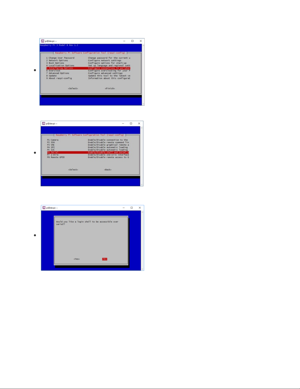
Run sudo raspi-config and select the following:
Interfacing Options
Serial
Select No on enabling the login shell
© Adafruit Industries https://learn.adafruit.com/circuitpython-on-raspberrypi-linux Page 42 of 59
Page 43

Select Yes on enabling serial port hardware
Once complete you should have no console and yes on serial interface:
Then reboot
Once you've rebooted, you can use the built in UART via /dev/ttyS0
Wire the GPS as follows:
GPS Vin to 3.3V (red wire)
GPS Ground to Ground (black wire)
GPS RX to TX (green wire)
GPS TX to RX (white wire)
Install the CircuitPython GPS Library
OK onto the good stuff, you can now install the Adafruit GPS CircuitPython library.
As of this writing, not
all
libraries are up on PyPI so you may want to search before trying to install. Look
for circuitpython and then the driver you want.
(If you don't see it you can open up a github issue on circuitpython to remind us (https://adafru.it/tB7)!)
© Adafruit Industries https://learn.adafruit.com/circuitpython-on-raspberrypi-linux Page 43 of 59
Page 44

Once you know the name, install it with
pip3 install adafruit-circuitpython-gps
You'll notice we also installed a
dependancy
called pyserial. This is a great thing about pip, if you have
other required libraries they'll get installed too!
We also recommend an adafruit-blinka update in case we've fixed bugs:
pip3 install --upgrade adafruit_blinka
Run that code!
The finish line is right up ahead. You can now run one of the (many in some cases) example scripts we've
written for you.
Check out the examples for your library by visiting the repository for the library and looking in the example
folder. In this case, it would be
https://github.com/adafruit/Adafruit_CircuitPython_GPS/tree/master/examples (https://adafru.it/Ca9)
Lets start with the simplest, the echo example
# SPDX-FileCopyrightText: 2021 ladyada for Adafruit Industries
# SPDX-License-Identifier: MIT
# Simple GPS module demonstration.
# Will print NMEA sentences received from the GPS, great for testing connection
# Uses the GPS to send some commands, then reads directly from the GPS
import time
import board
import busio
import adafruit_gps
# Create a serial connection for the GPS connection using default speed and
# a slightly higher timeout (GPS modules typically update once a second).
# These are the defaults you should use for the GPS FeatherWing.
# For other boards set RX = GPS module TX, and TX = GPS module RX pins.
uart = busio.UART(board.TX, board.RX, baudrate=9600, timeout=10)
# for a computer, use the pyserial library for uart access
# import serial
# uart = serial.Serial("/dev/ttyUSB0", baudrate=9600, timeout=10)
# If using I2C, we'll create an I2C interface to talk to using default pins
# i2c = board.I2C()
# Create a GPS module instance.
gps = adafruit_gps.GPS(uart) # Use UART/pyserial
# gps = adafruit_gps.GPS_GtopI2C(i2c) # Use I2C interface
# Initialize the GPS module by changing what data it sends and at what rate.
# These are NMEA extensions for PMTK_314_SET_NMEA_OUTPUT and
# PMTK_220_SET_NMEA_UPDATERATE but you can send anything from here to adjust
# the GPS module behavior:
# https://cdn-shop.adafruit.com/datasheets/PMTK_A11.pdf
# Turn on the basic GGA and RMC info (what you typically want)
gps.send_command(b"PMTK314,0,1,0,1,0,0,0,0,0,0,0,0,0,0,0,0,0,0,0")
# Turn on just minimum info (RMC only, location):
# gps.send_command(b'PMTK314,0,1,0,0,0,0,0,0,0,0,0,0,0,0,0,0,0,0,0')
© Adafruit Industries https://learn.adafruit.com/circuitpython-on-raspberrypi-linux Page 44 of 59
Page 45

# Turn off everything:
# gps.send_command(b'PMTK314,0,0,0,0,0,0,0,0,0,0,0,0,0,0,0,0,0,0,0')
# Tuen on everything (not all of it is parsed!)
# gps.send_command(b'PMTK314,1,1,1,1,1,1,0,0,0,0,0,0,0,0,0,0,0,0,0')
# Set update rate to once a second (1hz) which is what you typically want.
gps.send_command(b"PMTK220,1000")
# Or decrease to once every two seconds by doubling the millisecond value.
# Be sure to also increase your UART timeout above!
# gps.send_command(b'PMTK220,2000')
# You can also speed up the rate, but don't go too fast or else you can lose
# data during parsing. This would be twice a second (2hz, 500ms delay):
# gps.send_command(b'PMTK220,500')
# Main loop runs forever printing data as it comes in
timestamp = time.monotonic()
while True:
data = gps.read(32) # read up to 32 bytes
# print(data) # this is a bytearray type
if data is not None:
# convert bytearray to string
data_string = "".join([chr(b) for b in data])
print(data_string, end="")
if time.monotonic() - timestamp > 5:
# every 5 seconds...
gps.send_command(b"PMTK605") # request firmware version
timestamp = time.monotonic()
We'll need to configure this code to work with our UART port name.
If you're using a USB-to-serial converter, the device name is
probably
/dev/ttyUSB0 - but check
dmesg to make sure
If you're using the built-in UART on a Pi, the device name is /dev/ttyS0 - note that last character is a
zero
Comment out the lines that reference board.TX , board.RX and busio.uart and uncomment the lines that
import serial and define the serial device, like so:
# Define RX and TX pins for the board's serial port connected to the GPS.
# These are the defaults you should use for the GPS FeatherWing.
# For other boards set RX = GPS module TX, and TX = GPS module RX pins.
#RX = board.RX
#TX = board.TX
# Create a serial connection for the GPS connection using default speed and
# a slightly higher timeout (GPS modules typically update once a second).
#uart = busio.UART(TX, RX, baudrate=9600, timeout=3000)
# for a computer, use the pyserial library for uart access
import serial
uart = serial.Serial("/dev/ttyUSB0", baudrate=9600, timeout=3000)
And update the "/dev/ttyUSB0" device name if necessary to match your USB interface
Whichever method you use, you should see output like this, with $GP "NMEA sentences" - there probably
wont be actual location data because you haven't gotten a GPS fix. As long as you see those $GP strings
© Adafruit Industries https://learn.adafruit.com/circuitpython-on-raspberrypi-linux Page 45 of 59
Page 46

sorta like the below, you've got it working!
© Adafruit Industries https://learn.adafruit.com/circuitpython-on-raspberrypi-linux Page 46 of 59
Page 47
PWM Outputs & Servos
Adafruit Blinka supports PWMOut! This means you can easily pulse LEDs and control servos from your
Raspberry Pi using any GPIO pin! This page will walk you through wiring up an LED and a servo, and
provide an example for each.
Update Adafruit Blinka
Before getting started, make sure you're running the latest version of Adafruit Blinka. If you have not
already installed it, run the following:
pip3 install adafruit-blinka
If you've previously installed it, you should run a pip3 update:
pip3 install --upgrade adafruit-blinka
Once you're certain that you are running the latest version of Adafruit Blinka, you can continue!
Supported Pins
PWMOut is supported on all GPIO pins on the Raspberry Pi! They are independent, and each can have a
different frequency and duty cycle.
PWM - LEDs
This example will show you how to use PWM to pulse fade an LED.
First, wire up the LED to the Raspberry Pi.
LED - (negative) to Pi GND
LED + (positive) to 470Ω resistor
470Ω resistor to Pi GPIO5
Double-check you have the right wires connected to the right location, it can be tough to keep track of
pins as there are forty of them!
No additional libraries are needed, so we can go straight on to the example code.
Run the following code:
© Adafruit Industries https://learn.adafruit.com/circuitpython-on-raspberrypi-linux Page 47 of 59
Page 48

import time
import board
import pwmio
led = pwmio.PWMOut(board.D5, frequency=5000, duty_cycle=0)
while True:
for i in range(100):
# PWM LED up and down
if i < 50:
led.duty_cycle = int(i * 2 * 65535 / 100) # Up
else:
led.duty_cycle = 65535 - int((i - 50) * 2 * 65535 / 100) # Down
time.sleep(0.01)
Verify that the LED is pulsing. If not, check that it's wired to GPIO #5, the resistor is installed correctly, and
you have a ground wire to the Raspberry Pi.
Type control-C to quit.
Servo Control
In order to use servos, we take advantage of pulseio . You have two options. You can use the raw pulseio
calls to set the frequency to 50 Hz and then set the pulse widths. Or, you can use adafruit_motor which
manages servos for you quite nicely.
This section will cover both options.
Install adafruit_motor by running pip3 install adafruit-circuitpython-motor
First, wire up a servo to your Raspberry Pi:
Servo power (red wire) to Raspberry Pi 5V
Servo ground (black/brown wire) to Raspberry Pi
ground
Servo signal (yellow/white wire) to Raspberry Pi GPIO5
pulseio Servo Control
Run the following code:
© Adafruit Industries https://learn.adafruit.com/circuitpython-on-raspberrypi-linux Page 48 of 59
Page 49

import time
import board
import pwmio
# Initialize PWM output for the servo (on pin D5):
servo = pwmio.PWMOut(board.D5, frequency=50)
# Create a function to simplify setting PWM duty cycle for the servo:
def servo_duty_cycle(pulse_ms, frequency=50):
period_ms = 1.0 / frequency * 1000.0
duty_cycle = int(pulse_ms / (period_ms / 65535.0))
return duty_cycle
# Main loop will run forever moving between 1.0 and 2.0 mS long pulses:
while True:
servo.duty_cycle = servo_duty_cycle(1.0)
time.sleep(1.0)
servo.duty_cycle = servo_duty_cycle(2.0)
time.sleep(1.0)
The servo should sweep back and forth repeatedly. If it does not, verify your wiring matches the diagram
above.
Type control-C to quit.
adafruit_motor Servo Control
Run the following code:
import time
import board
import pwmio
from adafruit_motor import servo
# create a PWMOut object on Pin D5.
pwm = pwmio.PWMOut(board.D5, duty_cycle=2 ** 15, frequency=50)
# Create a servo object.
servo = servo.Servo(pwm)
while True:
for angle in range(0, 180, 5): # 0 - 180 degrees, 5 degrees at a time.
servo.angle = angle
time.sleep(0.05)
for angle in range(180, 0, -5): # 180 - 0 degrees, 5 degrees at a time.
servo.angle = angle
time.sleep(0.05)
The servo should sweep back and forth in steps. If it does not, verify your wiring matches the diagram
above.
Type control-C to quit.
© Adafruit Industries https://learn.adafruit.com/circuitpython-on-raspberrypi-linux Page 49 of 59
Page 50

More To Come!
That's just a taste of what we've got working so far
We're adding more support constantly, so please hold tight and visit the adafruit_blinka github
repo (https://adafru.it/BJX) to share your feedback and perhaps even submit some improvements!
If you'd like to contribute, but aren't sure where to start, check out the following guides:
Adding a Single Board Computer to PlatformDetect for Blinka (https://adafru.it/JFy)
Adding a Single Board Computer to Blinka (https://adafru.it/KEF)
© Adafruit Industries https://learn.adafruit.com/circuitpython-on-raspberrypi-linux Page 50 of 59
Page 51

CircuitPython & OrangePi
CircuitPython & OrangePi (https://adafru.it/DbB)
© Adafruit Industries https://learn.adafruit.com/circuitpython-on-raspberrypi-linux Page 51 of 59
Page 52

FAQ & Troubleshooting
There's a few oddities when running Blinka/CircuitPython on linux. Here's a list of stuff to watch for that we
know of!
This FAQ covers all the various platforms and hardware setups you can run Blinka on. Therefore, some of
the information may not apply to your specific setup.
Update Blinka/Platform Libraries
Most issues can be solved by forcing Python to upgrade to the latest blinka / platform-detect libraries.
Try running
sudo python3 -m pip install --upgrade --force-reinstall adafruit-blinka Adafruit-PlatformDetect
Getting an error message about "board" not found or "board" has no
attribute
Somehow you have ended up with either the wrong board module or no board module at all.
DO NOT try to fix this by manually installing a library named board . There is one out
there (https://adafru.it/NCE) and it has nothing to do with Blinka. You will break things if you install that
library!
The easiest way to recover is to simply force a reinstall of Blinka with:
python3 -m pip install --upgrade --force-reinstall adafruit-blinka
Mixed SPI mode devices
Due to the way we share an SPI peripheral, you cannot have two SPI devices with different 'mode/polarity'
on the same SPI bus - you'll get weird data
95% of SPI devices are mode 0, check the driver to see mode or polarity settings. For example:
LSM9DS1 is mode 1 (https://adafru.it/NCF), please use in I2C mode instead of SPI
MAX31865 is phase 1 (https://adafru.it/NCG), try using this on a separate SPI device, or read data
twice.
Why am I getting AttributeError: 'SpiDev' object has no attribute
'writebytes2'?
This is due to having an older version of spidev (https://adafru.it/JEi). You need at least version 3.4. This
should have been taken care of (https://adafru.it/NCH) when you installed Blinka, but in some cases it
does not seem to happen.
To check what version of spidev Python is using:
$ python3
© Adafruit Industries https://learn.adafruit.com/circuitpython-on-raspberrypi-linux Page 52 of 59
Page 53

Python 3.6.8 (default, Oct 7 2019, 12:59:55)
[GCC 8.3.0] on linux
Type "help", "copyright", "credits" or "license" for more information.
>>> import spidev
>>> spidev.__version__
'3.4'
>>>
If you see a version lower then 3.4 reported, then try a force upgrade of spidev with (back at command
line):
sudo python3 -m pip install --upgrade --force-reinstall spidev
No Pullup/Pulldown support on some linux boards or MCP2221
Some linux boards, for example, AllWinner-based, do not have support to set pull up or pull down on their
GPIO. Use an external resistor instead!
Getting OSError: read error with MCP2221
If you are getting a stack trace that ends with something like:
return self._hid.read(64)
File "hid.pyx", line 122, in hid.device.read
OSError: read error
Try setting an environment variable named BLINKA_MCP2221_RESET_DELAY to a value of 0.5 or higher.
Windows:
set BLINKA_MCP2221_RESET_DELAY=0.5
Linux:
export BLINKA_MCP2221_RESET_DELAY=0.5
This is a value in seconds to wait between resetting the MCP2221 and the attempt to reopen it. The reset
is seen by the operating system as a hardware disconnect/reconnect. Different operating systems can
need different amounts of time to wait after the reconnect before the attempt to reopen. Setting the
above environment variable will override the default reset delay time, allowing it to be increased as
needed for different setups.
© Adafruit Industries https://learn.adafruit.com/circuitpython-on-raspberrypi-linux Page 53 of 59
Page 54

Using FT232H with other FTDI devices.
Blinka uses the libusbk driver to talk to the FT232H directly. If you have other FTDI devices installed that
are using the FTDI VCP drivers, you may run into issues. See here for a possible workaround:
https://forums.adafruit.com/viewtopic.php?f=19&t=166999 (https://adafru.it/doW)
I can't get neopixel, analogio, audioio, rotaryio, displayio or pulseio to
work!
Some CircuitPython modules like may not be supported.
Most SBCs do not have analog inputs so there is no analogio
Few SBCs have neopixel support so that is only available on Raspberry Pi (and any others that have
low level neopixel protocol writing
Rotary encoders ( rotaryio ) is handled by interrupts on microcontrollers, and is not supported on SBCs
at this time
Likewise pulseio PWM support is not supported on many SBCs, and if it is, it will not support a carrier
wave (Infrared transmission)
For display usage, we suggest using python Pillow library or Pygame , we do not have displayio
support
We aim to have, at a minimum, digitalio and busio (I2C/SPI). This lets you use the vast number of driver
libraries
For analog inputs, the MCP3xxx library (https://adafru.it/CPN) will give you AnalogIn objects. For PWM
outputs, try the PCA9685 (https://adafru.it/tZF). For audio, use pygame or other Python3 libraries to play
audio.
Some libraries, like Adafruit_CircuitPython_DHT (https://adafru.it/Beq) will try to bit-bang if pulsein isn't
available. Slow linux boards (<700MHz) may not be able to read the pins fast enough), you'll just have to
try!
Help, I'm getting the message "error while loading shared libraries:
libgpiod.so.2: cannot open shared object file: No such file or directory"
It looks like libgpiod may not be installed on your board.
Try running the command: sudo apt-get install libgpiod2
When running the libgpiod script, I see the message: configure: error:
"libgpiod needs linux headers version >= v5.5.0"
Be sure you have the latest libgpiod.sh script and run it with the -l or --legacy flag:
./libgpiod.sh --legacy
© Adafruit Industries https://learn.adafruit.com/circuitpython-on-raspberrypi-linux Page 54 of 59
Page 55

All Raspberry Pi Computers Have:
1 x I2C port with busio (but clock stretching is not
supported in hardware, so you must set the I2C bus
speed to 10KHz to 'fix it')
2 x SPI ports with busio
1 x UART port with serial - note this is shared with the
hardware console
pulseio.pulseIn using gpiod
neopixel support on a few pins
No AnalogIn support (Use an MCP3008 or similar to add
ADC)
No PWM support (Use a PCA9685 or similar to add
PWM)
Google Coral TPU Dev Boards Have:
1 x I2C port with busio
1 x SPI ports with busio
1 x UART port with serial - note this is shared with the
hardware console
3 x PWMOut support
pulseio.pulseIn using gpiod
No NeoPixel support
No AnalogIn support (Use an MCP3008 or similar to add
ADC)
Orange Pi PC Plus Boards Have:
1 x I2C port with busio
1 x SPI ports with busio
1 x UART port with serial
pulseio.pulseIn using gpiod
No NeoPixel support
No AnalogIn support (Use an MCP3008 or similar to add
ADC)
No PWM support (Use a PCA9685 or similar to add
PWM)
© Adafruit Industries https://learn.adafruit.com/circuitpython-on-raspberrypi-linux Page 55 of 59
Page 56

Orange Pi R1 Boards Have:
1 x I2C port with busio
1 x SPI port with busio
1 x UART port with serial
No NeoPixel support
No AnalogIn support (Use an MCP3008 or similar to add
ADC)
No PWM support (Use a PCA9685 or similar to add
PWM)
Odroid C2 Boards Have:
1 x I2C port with busio
No SPI support
1 x UART port with serial - note this is shared with the
hardware console
No NeoPixel support
No AnalogIn support (Use an MCP3008 or similar to add
ADC)
No PWM support (Use a PCA9685 or similar to add
PWM)
DragonBoard 410c Boards Have:
2 x I2C port with busio
1 x SPI port with busio
1 x UART port with serial
No NeoPixel support
No AnalogIn support (Use an MCP3008 or similar to add
ADC)
No PWM support (Use a PCA9685 or similar to add
PWM)
© Adafruit Industries https://learn.adafruit.com/circuitpython-on-raspberrypi-linux Page 56 of 59
Page 57

NVIDIA Jetson Nano Boards Have:
2 x I2C port with busio
2 x SPI ports with busio
2 x UART port with serial - note one of these is shared
with the hardware console
No NeoPixel support
No AnalogIn support (Use an MCP3008 or similar to add
ADC)
No PWM support (Use a PCA9685 or similar to add
PWM)
FT232H Breakouts Have:
1x I2C port OR SPI port with busio
12x GPIO pins with digitalio
No UART
No AnalogIn support
No AnalogOut support
No PWM support
If you are using Blinka in FT232H mode (https://adafru.it/FWD),
then keep in mind these basic limitations.
SPI and I2C can not be used at the same time since they
share the same pins.
GPIO speed is not super fast, so trying to do arbitrary bit
bang like things may run into speed issues.
There are no ADCs.
There are no DACs.
UART is not available (its a different FTDI mode)
MCP2221 Breakouts Have:
1x I2C port with busio
4x GPIO pins with digitalio
3x AnalogIn with analogio
1x AnalogOut with analogio
1x UART with pyserial
No PWM support
No hardware SPI support
If you are using Blinka in MCP2221 mode, then keep in mind
these basic limitations.
GPIO speed is not super fast, so trying to do arbitrary bit
bang like things may run into speed issues.
UART is available via pyserial , the serial COM port
shows up as a second USB device during enumeration
© Adafruit Industries https://learn.adafruit.com/circuitpython-on-raspberrypi-linux Page 57 of 59
Page 58

© Adafruit Industries https://learn.adafruit.com/circuitpython-on-raspberrypi-linux Page 58 of 59
Page 59

© Adafruit Industries Last Updated: 2021-05-01 09:02:28 PM EDT Page 59 of 59
 Loading...