

Page 1
5" Display Kippah Portable Raspberry Pi
Created by Ruiz Brothers
Last updated on 2021-03-07 07:41:10 PM EST
Page 2

2
4
4
4
5
5
6
6
6
7
7
8
8
9
9
10
12
13
13
15
18
18
18
18
19
19
20
20
20
20
20
21
21
22
23
24
25
25
25
26
27
28
28
30
30
30
31
31
32
32
Guide Contents
Guide Contents
Overview
Portable Pi
Touch screen UPDATE
Kippah Sauce
PowerBoost 1000C
Built-in Audio (Optional)
3D Printing
Prerequisite Guides
Parts
Tools and Supplies
Circuit Diagram
The Circuit Diagram
Installation
Connect Display
Update & Upgrade
Install and Try raspi-gpio
Install Device Tree Blob
Update configuration
Touch screen support
3D Printing
Customize Design
Materials
Tolerances
Bed Leveling
Clean up
Assembly
Wiring
Testing
Mounting
Process
Slide Switch
Prep Wires
Tin Wires and Switch
Connect Wires to Switch
Slide Switch
Audio Cable
Measure and Cut
Strip It!
Tin Wire
Extend Ground
Insulate Groud
Audio Cable
Amplifier
Prep Wires
Tin Wires
Connect Wires to Amp
Solder Audio Cable to Amp
Connect Speaker to Amp
Audio Circuit
© Adafruit Industries https://learn.adafruit.com/portable-kippah-pi Page 2 of 53
Page 3

33
33
33
34
34
35
35
36
37
38
39
39
39
40
40
41
42
43
43
43
44
44
45
45
46
46
47
48
48
48
48
49
49
50
51
51
51
52
Kippah
Prep Wires
Tin Kippah and Wires
Connect wires to Kippah
Wired Kippah
Powerboost 1000C
Install Switch
Machine Screws
Install Screws
Connect Switch to PowerBoost 1000C
Mounting Components
Install Amp
Connect PAM8302 to PowerBoost 1000C
Install Speaker
Plug Audio Cable
Install Raspberry Pi
Circuit Checkpoint
Kippah Display
Install 40-pin FPC cable
Install Kippah
Connect Kippah to PowerBoost 1000C
Install Display
Mount Display
Connect Extension to Display
Connect 40-pin cable to Extension
Plug in Battery
Test Circuit
Closing it up
Cable Management
Ports
Fasten Shut
Closed Up
Portable Kippah Pi
Tripod Adapter
Mountable Pi
Use and Commence Pi
What's that orange keyboard?
Made This? Let us know!
© Adafruit Industries https://learn.adafruit.com/portable-kippah-pi Page 3 of 53
Page 4
Overview
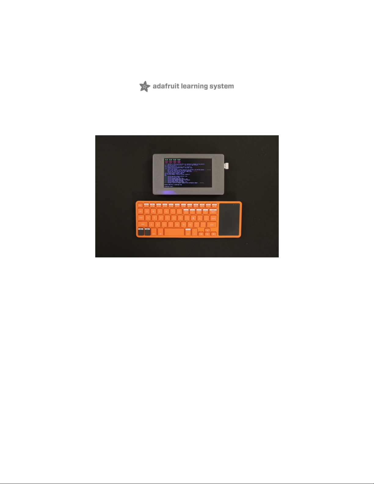
Portable Pi
There are many applications where a portable Raspberry Pi can be really useful. In most general usecases, it's convenient to have a Raspberry Pi, display and battery contained in a nice package. In this
project, we'll put together a portable Raspberry Pi with a battery and display. This project is relatively
simple to put together and only requires a few wired connections.
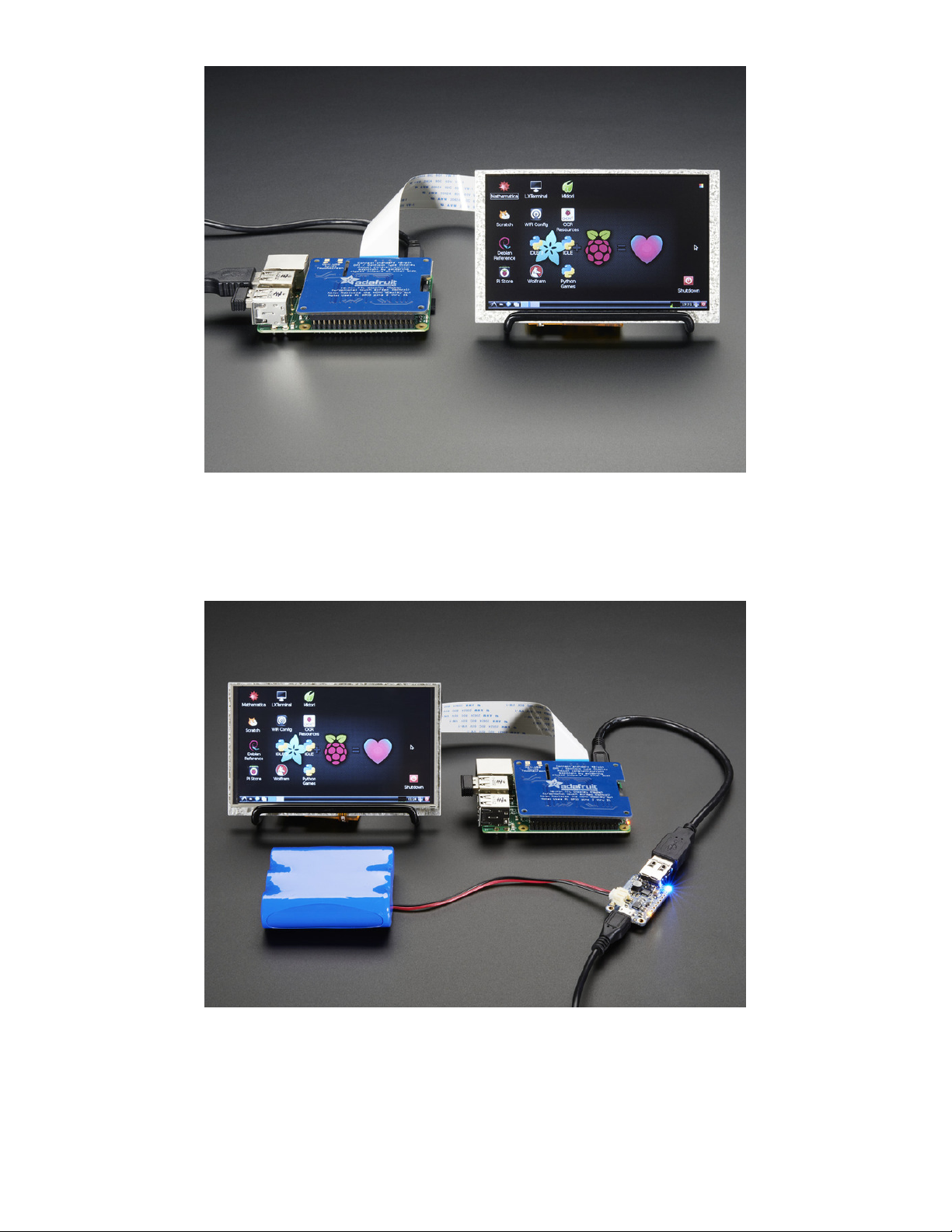
Touch screen UPDATE
New version of enclosure now works with 5" 40-pin TFT Display with Touchscreen and Adafruit DPI TFT
Kippah for Raspberry Pi with Touch Support
http://www.adafruit.com/product/1596 (https://adafru.it/iDa)
http://www.adafruit.com/product/2453 (https://adafru.it/iDb)
Follow the Kippah Touch tutorial (https://adafru.it/kED) for setting up the software. The 3D printed parts
are on thingiverse (labled v2).
© Adafruit Industries https://learn.adafruit.com/portable-kippah-pi Page 4 of 53
Page 5
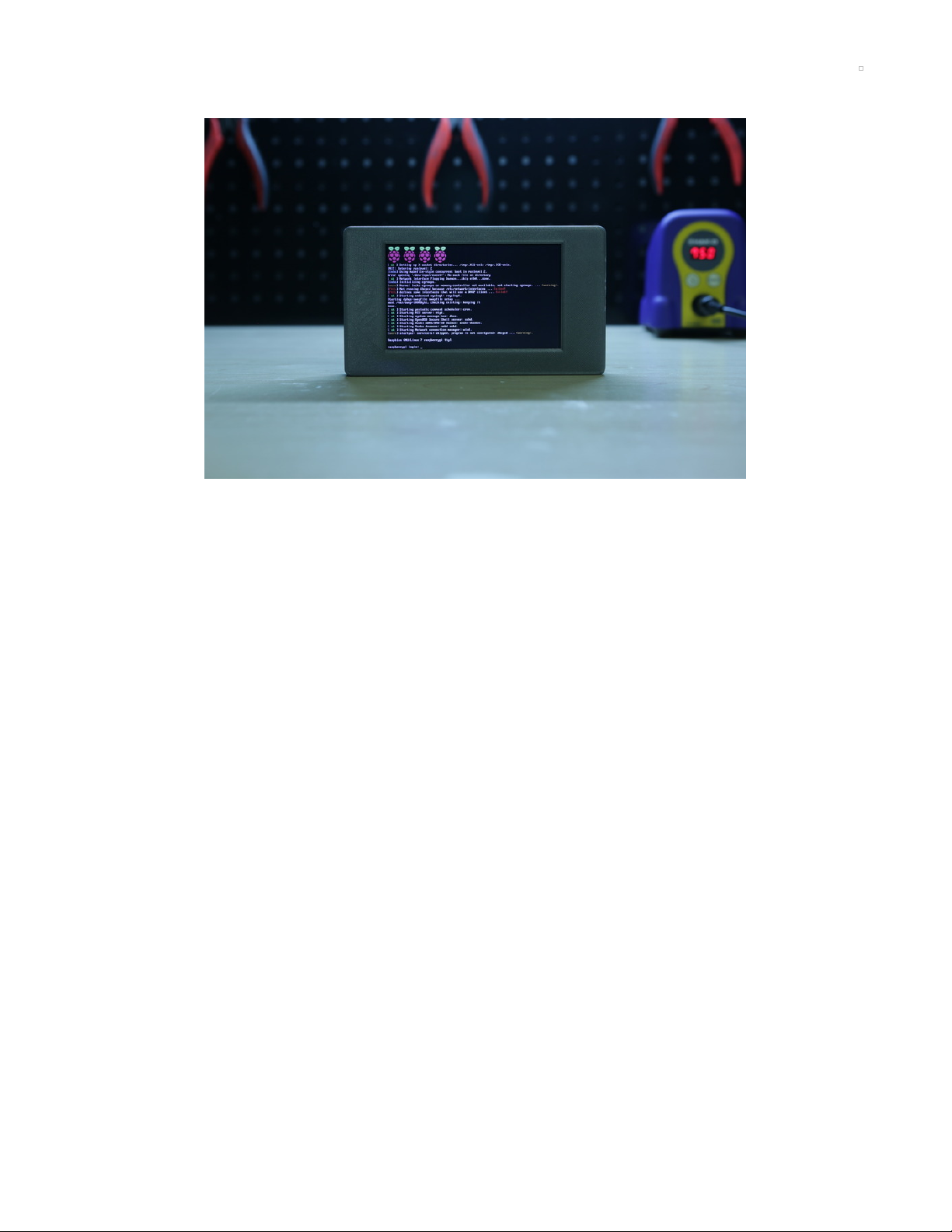
Kippah Sauce
This project utilizes the Adafruit DPI Display Kippah "hat-like" board to drive a 5" TFT display without the
extra cost and baggage of an HDMI decoder. Kippah gives you nice ultra-fast 18-bit color display. This
works great with the 5" displays at 800x480. This display is 'native' so it gets all the graphics accelleration
capabilities, instant refresh, etc. you would get from an HDMI display.
PowerBoost 1000C
The PowerBoost 1000C provides 5V @ 1A of regulated power to the Raspberry Pi, Kippah and PAM8302
amplifier. On board charging let's you recharge a lipo battery over microUSB. In this project we are able to
comfortably fit a 2500mAh lipo battery in the 3D printed enclosure.
© Adafruit Industries https://learn.adafruit.com/portable-kippah-pi Page 5 of 53
Page 6
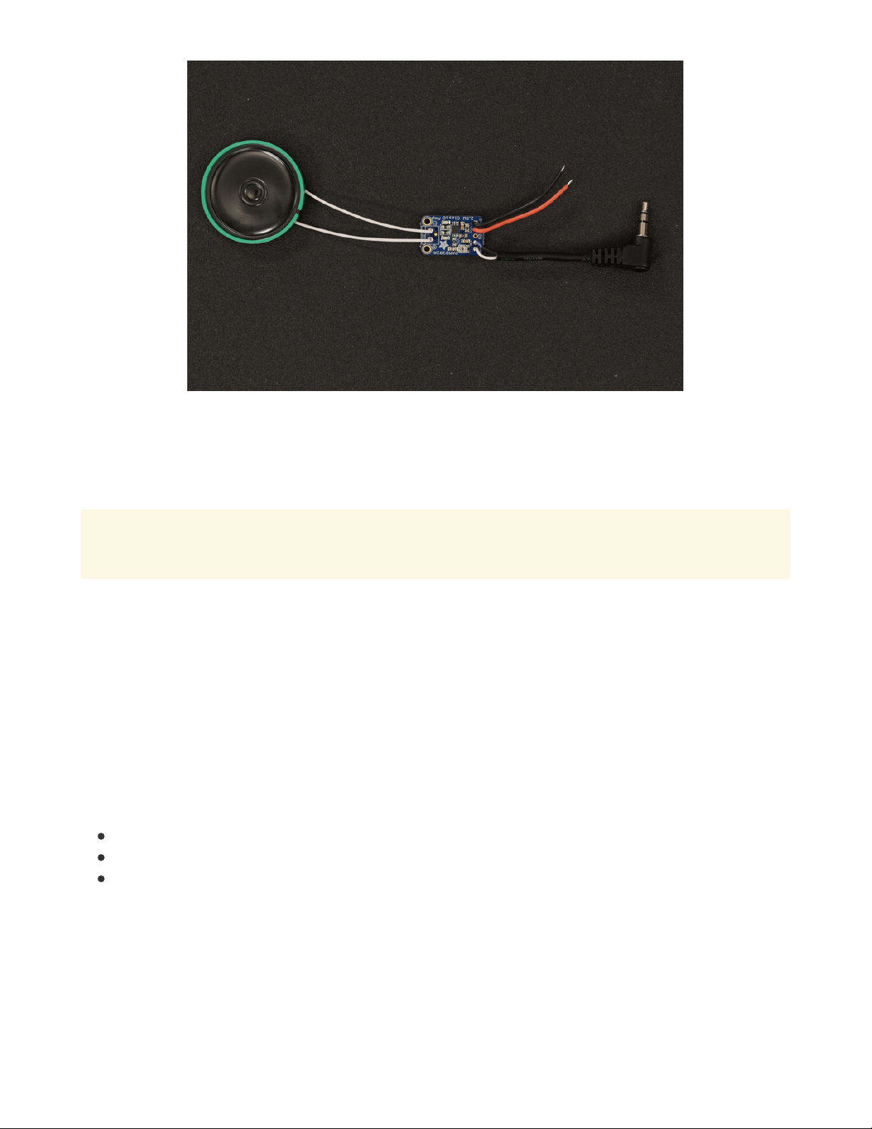
Built-in Audio (Optional)
There's enough room in the enclosure to fit a thin plastic speaker and a mono Class D audio amplifier. We
can wire up an audio cable (3.5mm jack) to the amp and plug it into the audio jack on the Raspberry Pi.
This portion can be optional, but the keep in mind there's no access to the audio jack on this 3D printed
enclosure.
In most cases (with terminal), there is noticeable audio interference. The interference is minimized
with the use of startx and emulationstation.
3D Printing
This project enclosure was designed specially to fit the components listed in the sidebar and below. The
parts unfortunately will not fit on smaller print beds (like the Printrbot Simple). To print the parts, you'll
need access to a printer with a minimum build plate of 100mm x 168mm x 30mm.
No 3D printer? You could send the parts to be printed by a service like 3D Hubs, MakerXYZ or shapeways.
You could also try checking out your local hacker/maker space or library.
Prerequisite Guides
Check out the guides below to get a better understanding of the Kippah and the Raspberry Pi 2 or B+ (The
enclosure is compatible with both).
Adafruit DPI Display Kippah (https://adafru.it/iD8)
Introducing Raspberry Pi 2 (https://adafru.it/iD9)
Introducing Raspberry Pi B+ (https://adafru.it/dP7)
© Adafruit Industries https://learn.adafruit.com/portable-kippah-pi Page 6 of 53
Page 7
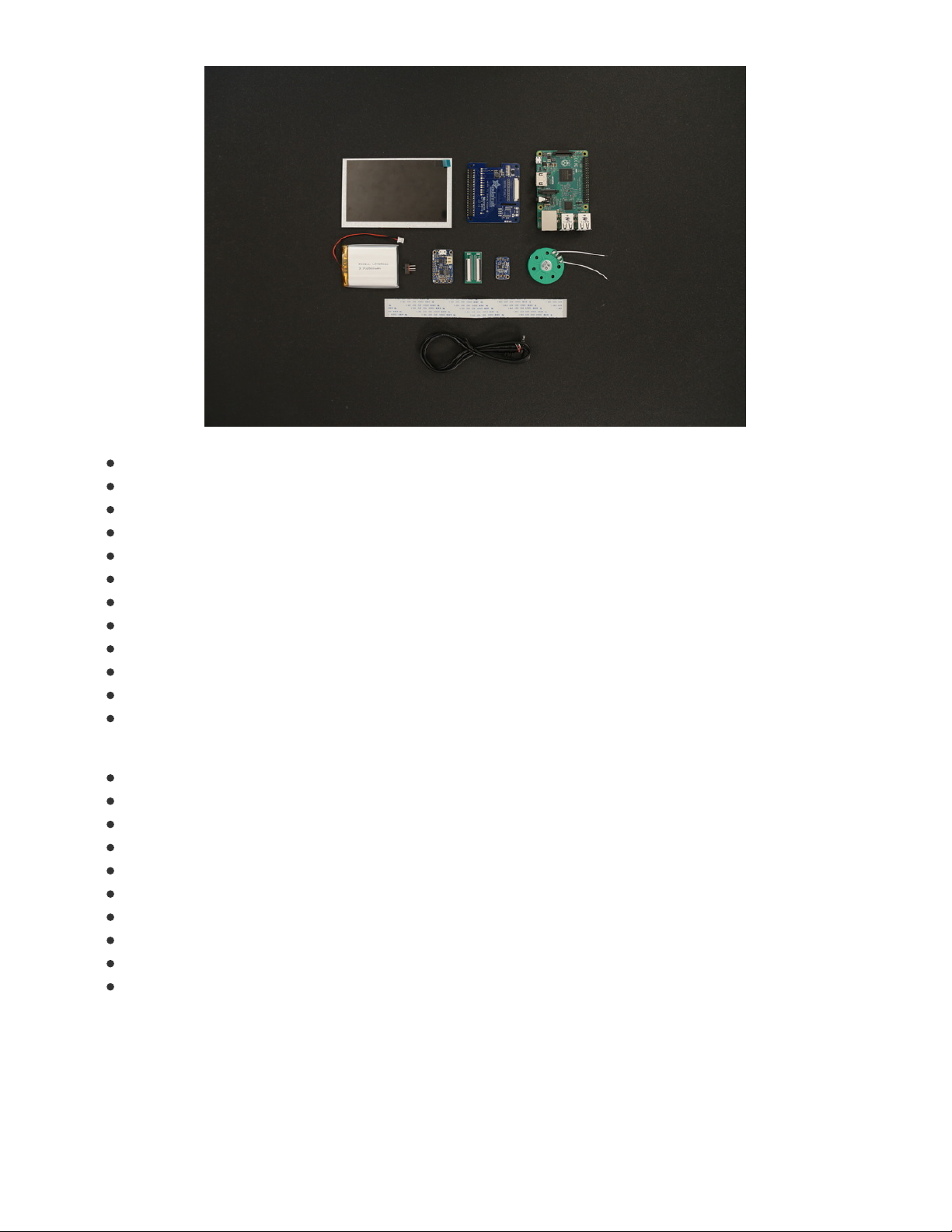
Parts
Adafruit DPI Display Kippah
Raspberry Pi 2
Raspberry Pi B+
5" TFT display 40-pin
PowerBoost 100C
PAM8302 Amplifier
Thin plastic speaker
2500mAh lithium polymer battery
Slide switch
Right-angle 3.5mm stereo plug to pigtail cable
3/8" to 1/4" Adapter Screw (http://adafru.it/2392)
Swivel-Head Pan Tilt (http://adafru.it/2464)
Tools and Supplies
3D Printer
Filament
Wire Strippers/Cutters
30/26AWG silicone-coated stranded wire
Soldering Iron
Solder
Helping-third hands
Panavise Jr.
6 #2-56 3/8 flat Phillips machine screws
8 #4-40 3/8 flat Phillips machine screws
© Adafruit Industries https://learn.adafruit.com/portable-kippah-pi Page 7 of 53
Page 8
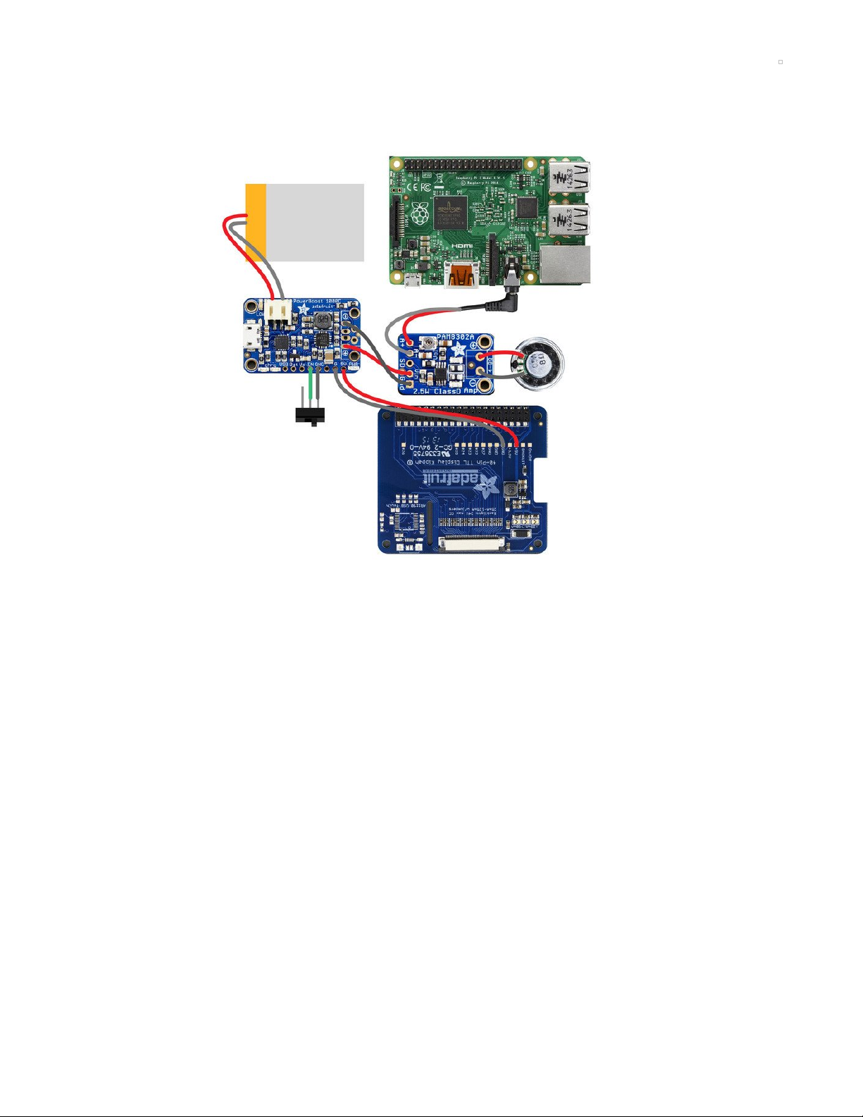
Circuit Diagram
The Circuit Diagram
The slide switch connects to the EN and GND pins on the PowerBoost1000C.
Connect 5V and GND on the Kippah to the 5V and GND pins on the PowerBoost 1000C.
The Vin and GND pins audio amplifier will connect to a set of positive+ and negative- pins on
PowerBoost1000C.
The speaker connects to the positive+ and negatives- audio out pin on the PAM8302 amplifier.
Stereo audio cable plugs into the audio jack on the Raspberry Pi and connects to A+ and A- on the amp.
The 5" TFT display connects to a 40-pin FPC extention connector. An included 40-pin cable connects from
the Kippah to the extension to the 5" display.
JST cable from the lipo battery connects directly to the JST port on the PowerBoost1000C.
© Adafruit Industries https://learn.adafruit.com/portable-kippah-pi Page 8 of 53
Page 9
Installation
If you just plug in the DPI Kippah, it won't work on a fresh installation of Raspbian! You must set up the
special device tree overlay configuration!
However, its not too bad, check it out below!
We've only tested this device tree overlay/firmware with Raspbian. Since its a bit of a hack, it doesn't
work with the native pre-boot 'NooBS' screen. However, it does come up immediately with Raspbian
(e.g. you get to see the rainbow square screen)
Note these instructions are tested to work with Raspbian Stretch as of 2019/04/11
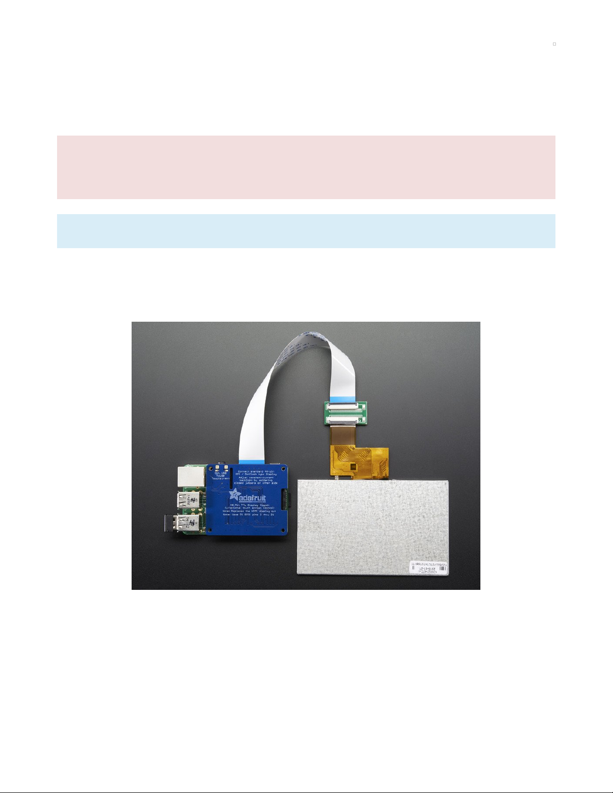
Connect Display
The DPI Kippah has a 40-pin TFT connector. This is a semi-standard connector. A majority of 3.5", 4.3",
5.0" and 7.0" dot-clock DPI displays have this 'standard 40-pin' connector.
Check the Downloads page for an example datasheet so you can check if your display is compatible. All
Adafruit 40-pin TFT TTL displays work, we do not guarantee any other displays work.
In fact, if you connect a display that does not match the right pinout, you could easily fry the display if
the 20V backlight pin ends up connected to a logic pin!
To connect, gently pull on the two black 'ears' on the FPC connector, and plug in the display so the
gold/silver metalic pins are facing 'up' away from the PCB.
© Adafruit Industries https://learn.adafruit.com/portable-kippah-pi Page 9 of 53
Page 10
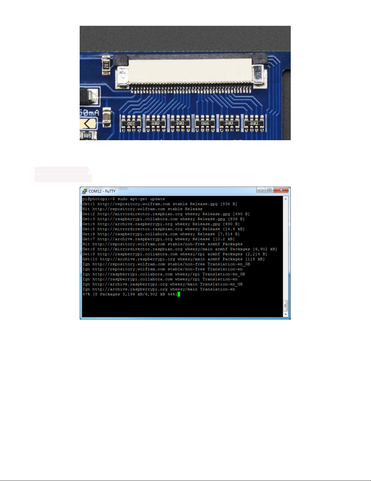
Update & Upgrade
Start by updating and upgrading your Raspberry Pi to the latest software.
sudo apt-get update
sudo apt-get upgrade
© Adafruit Industries https://learn.adafruit.com/portable-kippah-pi Page 10 of 53
Page 11
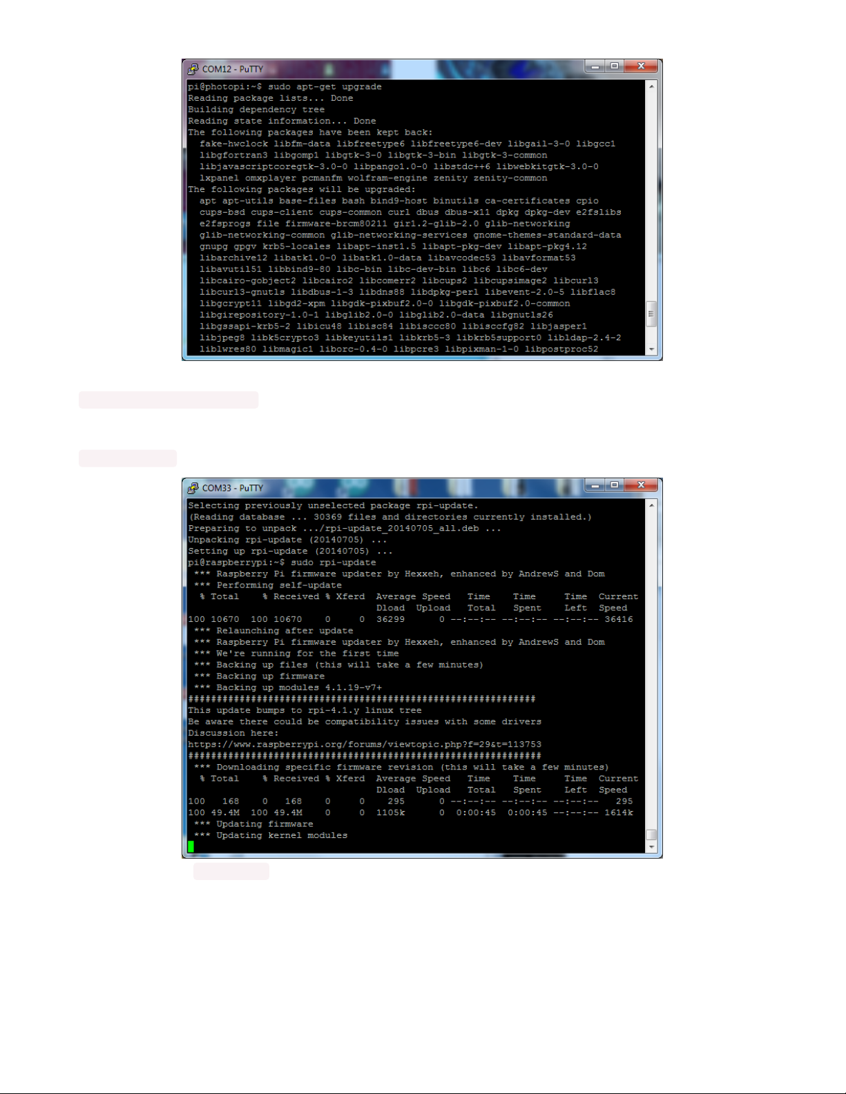
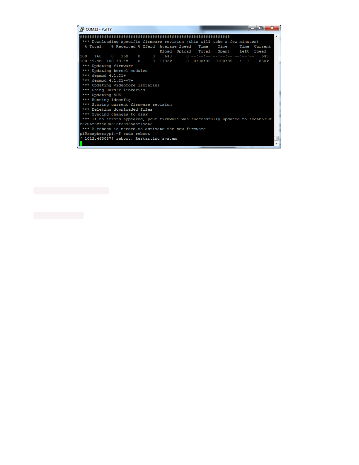
We want to get the most recent recent kernel and firmware, so run
sudo apt-get install rpi-update
and then
sudo rpi-update
Then reboot with sudo reboot
© Adafruit Industries https://learn.adafruit.com/portable-kippah-pi Page 11 of 53
Page 12
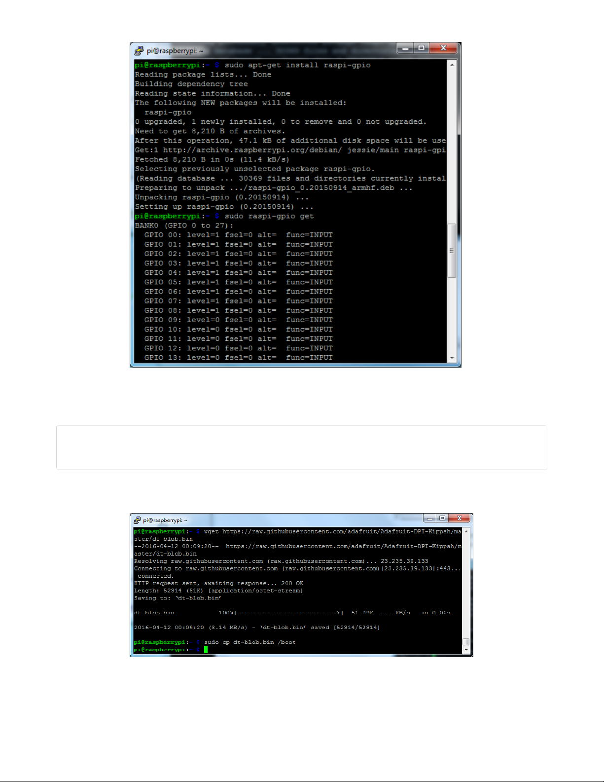
Install and Try raspi-gpio
To help us debug/make sure we have the right device tree blob, we'll use a tool called raspi-gpio
Install it with
sudo apt-get install raspi-gpio
Then you can run it with
sudo raspi-gpio get
When you run it this time, you'll see the first 'bank' of GPIO pins set to, essentially
GPIO nn: level=1 fsel=0 alt= func=INPUT
© Adafruit Industries https://learn.adafruit.com/portable-kippah-pi Page 12 of 53
Page 13
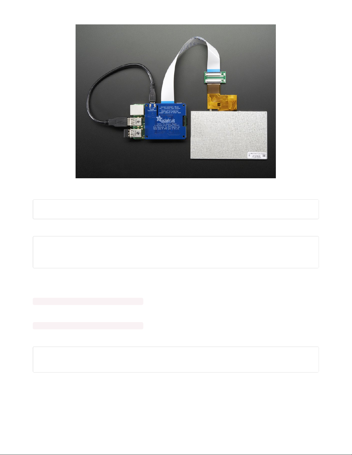
Install Device Tree Blob
Now download and install the DPI device tree blob (tip o' the hat to
aBUGsworstnightmare (https://adafru.it/mFi)) from github by running:
cd ~
wget https://raw.githubusercontent.com/adafruit/Adafruit-DPI-Kippah/master/dt-blob.bin
sudo cp dt-blob.bin /boot/
in your Pi's command line, to change directories to the home directory, download the blob, then copy it in
/boot
Update configuration
Finally, we'll tell the Pi to use the attached DPI display. The following will work for our 5" and 7" 800x480
displays. Both touch and non-touch displays use the same setup here
© Adafruit Industries https://learn.adafruit.com/portable-kippah-pi Page 13 of 53
Page 14

Start by editing with
sudo nano /boot/config.txt
and add the following lines at the bottom
# Disable spi and i2c, we need these pins.
dtparam=spi=off
dtparam=i2c_arm=off
# Set screen size and any overscan required
overscan_left=0
overscan_right=0
overscan_top=0
overscan_bottom=0
framebuffer_width=800
framebuffer_height=480
# enable the DPI display
enable_dpi_lcd=1
display_default_lcd=1
# Enable DPI overlay
dtoverlay=dpi24
# set up the size to 800x480
dpi_group=2
dpi_mode=87
# set up the hsync/vsync/clock polarity and format
dpi_output_format=454661
# set up the size to 800x480
hdmi_timings=800 0 40 48 88 480 0 13 3 32 0 0 0 60 0 32000000 6
For 4.3" TFT use the following:
© Adafruit Industries https://learn.adafruit.com/portable-kippah-pi Page 14 of 53
Page 15

# Disable spi and i2c, we need these pins.
dtparam=spi=off
dtparam=i2c_arm=off
# Set screen size and any overscan required
overscan_left=0
overscan_right=0
overscan_top=0
overscan_bottom=0
framebuffer_width=480
framebuffer_height=272
# enable the DPI display
enable_dpi_lcd=1
display_default_lcd=1
# set up the size to 480x272
dpi_group=2
dpi_mode=87
# set up the hsync/vsync/clock polarity and format
dpi_output_format=520197
# set up the size to 480x272
hdmi_timings=480 0 40 48 88 272 0 13 3 32 0 0 0 60 0 32000000 3
This sets up the screen, if you ever want to temporarily 'undo the DPI Hat install' just delete these lines
enable_dpi_lcd=1
display_default_lcd=1
To finish installation, just run sudo reboot
Touch screen support
If you have a DPI HAT with touchscreen circuitry installed
and
a touch-screen display, you can easily use it
for touch screen support
A microUSB cable is required (not included) connect it from the MicroUSB connector on the HAT into one
of the Pi's USB port
© Adafruit Industries https://learn.adafruit.com/portable-kippah-pi Page 15 of 53
Page 16
No drivers are required! However, you'll likely want to calibrate the screen. We have a calibration helper
python script. Start by installing python-pip and pyusb version 1.0.0b1
sudo apt-get install python-pip
sudo pip install pyusb==1.0.0b1
Then grab the code and example gradient
cd ~
wget http://adafru.it/ar1100py
mv ar1100py ar1100.py
wget http://adafruit-download.s3.amazonaws.com/gradient800x480.jpg
If you are running it on a 5" display, continue as is.
If you are running it on a 7" display, edit with nano ar1100.py and change this line:
writeeeprom = CALIBRATED_5IN_800x480;
to
writeeeprom = CALIBRATED_7IN_800x480;
Then run the calibrator with:
cd ~
chmod +x ar1100.py
sudo python ar1100.py
Its normal for the first time you run it, it will complain " Couldn't find generic either " just run it again!
© Adafruit Industries https://learn.adafruit.com/portable-kippah-pi Page 16 of 53
Page 17
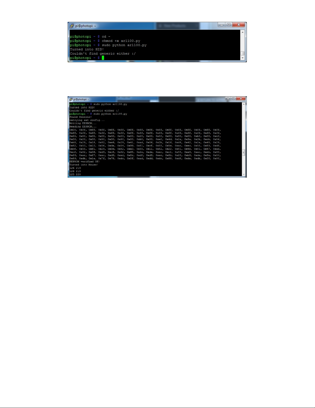
Just hit the up arrow on your keyboard and return, to rerun sudo python ar1100.py
This time it will continue, program the AR1100 with the calibration data, and give you a rainbow display.
When done, hit Escape on your keyboard
© Adafruit Industries https://learn.adafruit.com/portable-kippah-pi Page 17 of 53
Page 18

3D Printing
The parts are optimized to print with no support material. The two enclosure parts are held together with
machine screws. They're oriented in center and should be good to print as is.
To print the parts, you'll need access to a printer with a minimum build plate of 100mm x 168mm x
30mm.
https://adafru.it/foD
https://adafru.it/foF
5ip2-v2-top.stl
230c Extruder
10% Infill
2 Shells
90/120 speeds
about 1hr 20min
5ip2-v2-bot.stl-
about 1hr and
40min
sd-cover.stl - about 5min
Customize Design
You can modify the original solids in the CAD files to make a custom project.
Materials
The parts can be printed in different types of filament. The most common filaments like PLA and ABS will
do just fine but you can of course experiement with copperFill, bambooFill, Semiflex, PET and Nylon.
Tolerances
https://adafru.it/foD
https://adafru.it/foF
© Adafruit Industries https://learn.adafruit.com/portable-kippah-pi Page 18 of 53
Page 19

The parts were tested with common printing settings (listed in the table). With a parameter of 2 shells,
theres only a few areas where tolerances really matters - the port cutouts and the mounting holes.
Test fit the parts by inserting the top enclosure part over the Raspberry Pi. Check to see if the cutouts fit
over the USB and ethernet ports. If the cutout is too tight, you can loosen it with a filing tool.
The standoffs with counter bores should fit the machine screws listed in the BOM. These can be threaded
by fastening in the appropriate sized screw.
Bed Leveling
Any parts with large surface require a well leveled build plate. If you're using a heated bed, you can
minimize warping. Blue painters tape, build tak, and sticky adhesives can help keep your part flat and
adhere to the bed.
Clean up
If there's any string or artifacts left over from retraction and oozing, clean up the part by trimming them off
using a pair of flush snips.
© Adafruit Industries https://learn.adafruit.com/portable-kippah-pi Page 19 of 53
Page 20

Assembly
Wiring
First section of the assembly requires measuring wires, cutting, stripping, tinning and soldering. It's a good
idea to connect the component and test the circuit before mounting anything to the enclosure.
Testing
With the components wired up, we'll test power to ensure all the connections are solid. We connect the
display to the kippah and the Raspberry Pi to ensure the circuit is working properly before mounting.
Mounting
Once the components are wired up, you'll mount sections of the circuit to the enclosure using machine
screws. This will keep everything secured in place.
Process
This assembly is segmented and formatted linearly to make the build an easy experience. Keeping
the circuit modular allows you to trouble shoot more easily and makes mounting parts more optimal.
© Adafruit Industries https://learn.adafruit.com/portable-kippah-pi Page 20 of 53
Page 21

Slide Switch
Prep Wires
Measure, cut and strip two pieces of 30AWG silicone-coated
stranded wire.
© Adafruit Industries https://learn.adafruit.com/portable-kippah-pi Page 21 of 53
Page 22

Tin Wires and Switch
Use a pair of helping third hands to secure wires/switch in
place. Appy small amount of solder to the tips of the wires
and the terminals on the slide switch.
© Adafruit Industries https://learn.adafruit.com/portable-kippah-pi Page 22 of 53
Page 23

Connect Wires to Switch
Solder both wires to two terminals on the slide switch (one in
the center, and another next to that). Cut a piece of shrink
tubing and slide that onto the wire to cover it up. Apply some
heat to secure the connections.
Trim off the unused terminals on the side switch.
© Adafruit Industries https://learn.adafruit.com/portable-kippah-pi Page 23 of 53
Page 24

Slide Switch
The slide switch is now ready for some action! Let's set it aside and get to the next section.
© Adafruit Industries https://learn.adafruit.com/portable-kippah-pi Page 24 of 53
Page 25
Audio Cable
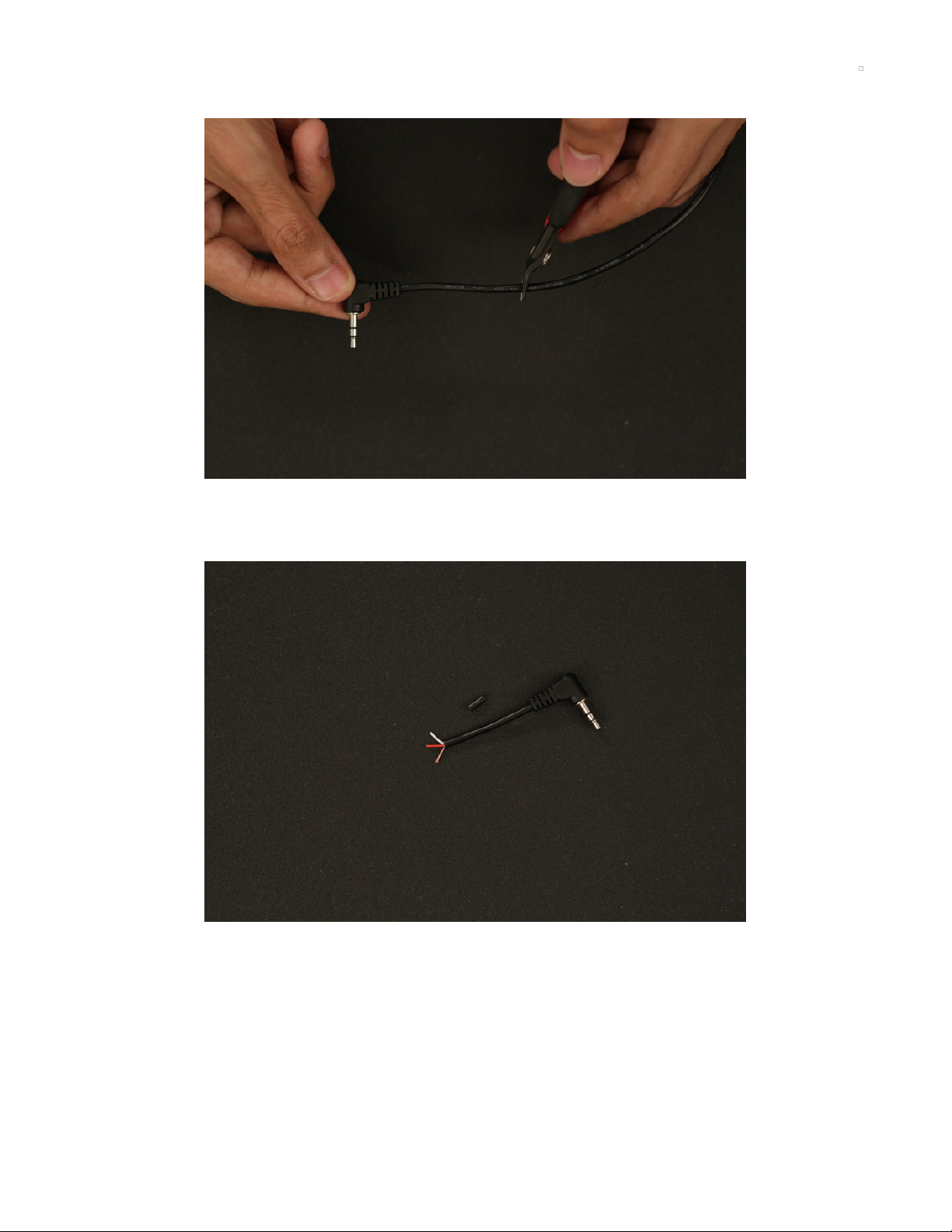
Measure and Cut
Grab the right-angled stereo plug to pigtail cable and measure up the length you'll need. If you cut it too
short, you can always extend by splicing with a longer wire.
Strip It!
You'll want to remove about 10mm of insultation from the audio cable. Use wire cutters or a hobby knife to
strip the wire. Carefuly bundle the stranded wire and twist it together to make a uniform wire - this is the
ground connection.
© Adafruit Industries https://learn.adafruit.com/portable-kippah-pi Page 25 of 53
Page 26

Tin Wire
Secure the audio cable to third-helping hands. Apply solder to
the ground connection. Trim one of the insulated wires (red
or white, doesn't matter these are the 'left' and 'right'
channels). We only need one channel and the ground
connection. Strip and tin the remaining wire.
© Adafruit Industries https://learn.adafruit.com/portable-kippah-pi Page 26 of 53
Page 27

Extend Ground
Trim off about half of the tinned ground connection (it's too
long). Prep a new piece of AWG30 silicone-coated stranded
wire by measuring, cutting and stripping. Solder it to the
ground connection.
© Adafruit Industries https://learn.adafruit.com/portable-kippah-pi Page 27 of 53
Page 28

Insulate Groud
Slide a piece of shrink tubing over the ground connection and
apply heat to secure the connection. Cut the ground wire to
match the length of the channel wire and tin the tip.
Audio Cable
This pigtail is ready for baking!
© Adafruit Industries https://learn.adafruit.com/portable-kippah-pi Page 28 of 53
Page 29

Amplifier
Prep Wires
You can lay down the Powerboost 1000C and PAM8302 amplifier on the enclosure to get an idea for how
long the power and ground wires need to be. Cut two pieces of 26AWG silicone-coated stranded wires.
Tin Wires
Strip the tips of both wire using wire strippers and secure the
wires to third-helping hands. Apply a small amount of solder
to tin the tips.
© Adafruit Industries https://learn.adafruit.com/portable-kippah-pi Page 29 of 53
Page 30

Connect Wires to Amp
Apply solder to the pins on the amplifier. To solder the wires
to the pins, hold the tip of the soldering iron to the solder joint
and insert the wire.
Solder Audio Cable to Amp
Connect the audio cable to the amp by heating A+ and A- pins with the tip of the soldering iron. Insert the
white channel wire to A+ and the ground wire to A-.
© Adafruit Industries https://learn.adafruit.com/portable-kippah-pi Page 30 of 53
Page 31

Connect Speaker to Amp
Apply solder to the positive and negative pins on the amplifier
and insert the + and - wires from the speaker to the amp.
Audio Circuit
This beastly audio setup is ready for some thumpin' beats!
© Adafruit Industries https://learn.adafruit.com/portable-kippah-pi Page 31 of 53
Page 32

© Adafruit Industries https://learn.adafruit.com/portable-kippah-pi Page 32 of 53
Page 33

Kippah
Prep Wires
Lay Kippah and Powerboost 1000c on the enclosure to get an idea of wire length. A bit of extra slack
is OK, you can shorten it later. 26AWG silicone-coated stranded wire is recommend for power.
Tin Kippah and Wires
Strip and tin the two wires then, apply solder to the 5V and
GND pins on the Kippah.
© Adafruit Industries https://learn.adafruit.com/portable-kippah-pi Page 33 of 53
Page 34
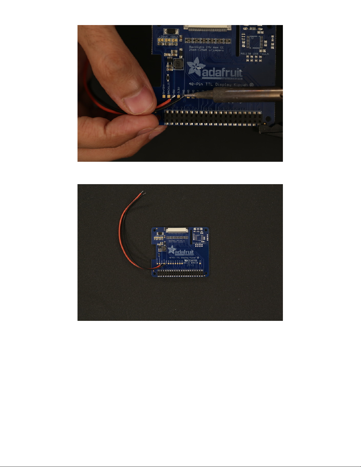
Connect wires to Kippah
Appy heat to the solder joints on Kippah and place the tip of the wires to the 5V and GND pads.
Wired Kippah
This stylin' Kippah is ready for sum Raspberré Pi!
© Adafruit Industries https://learn.adafruit.com/portable-kippah-pi Page 34 of 53
Page 35

Powerboost 1000C
Install Switch
Insert the wires from the switch to the cutout near the bottom
of the enclosure. Press the switch into the cutout to snap it
into place.
© Adafruit Industries https://learn.adafruit.com/portable-kippah-pi Page 35 of 53
Page 36

Machine Screws
You'll need two #4-40 3/8th flat phillips machine screws to secure the PowerBoost 1000C to the
enclosure.
© Adafruit Industries https://learn.adafruit.com/portable-kippah-pi Page 36 of 53
Page 37

Install Screws
Insert the two screws to the bottom of the enclosure and
fasten them in until the tip of the thread pokes through the
top of the standoff. Lay the PowerBoost 1000C over the
screws and fasten the screws all the through while holding
the PCB in place.
© Adafruit Industries https://learn.adafruit.com/portable-kippah-pi Page 37 of 53
Page 38

Connect Switch to PowerBoost 1000C
Solder the two wires from the slide switch to pins EN and GND on the PowerBoost 1000C.
© Adafruit Industries https://learn.adafruit.com/portable-kippah-pi Page 38 of 53
Page 39

Mounting Components
Install Amp
Lay the PAM8302 PCB over the standoffs on the enclosure
and hold it in place while you fasten a single machine screw
to the bottom of the enclosure.
Connect PAM8302 to PowerBoost 1000C
Get the power and ground wires from the PAM8302 amplifier and solder them to the positive and
negative pins on the PowerBoost 1000C.
© Adafruit Industries https://learn.adafruit.com/portable-kippah-pi Page 39 of 53
Page 40

Install Speaker
Insert the thin plastic speaker into the cylindrical cavity. Press it down until it snaps into place. Tolerances
should be pretty tight.
Plug Audio Cable
Insert the 3.5mm connector from the audio cable into the audio jack on the Raspberry Pi
© Adafruit Industries https://learn.adafruit.com/portable-kippah-pi Page 40 of 53
Page 41
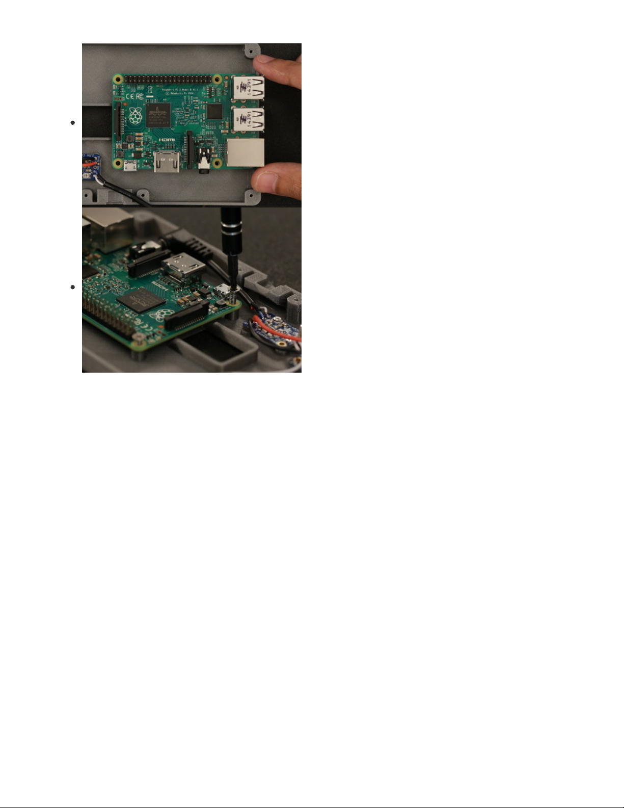
Install Raspberry Pi
Lay the PCB over the standoffs with the ports facing the
cutout. Line up the mounting holes on the Pi with the holes on
the standoffs. Insert four #4-40 3/8 flat Phillips machine
screws and fasten them into place from the top of the Pi.
© Adafruit Industries https://learn.adafruit.com/portable-kippah-pi Page 41 of 53
Page 42

Circuit Checkpoint
The bottom half of the project is pretty much finished. The Rasp Pi and audio setup is installed, mounted
and wired!
© Adafruit Industries https://learn.adafruit.com/portable-kippah-pi Page 42 of 53
Page 43

Kippah Display
Install 40-pin FPC cable
Open the latch from the Kippah PCB and insert the 40-pin FPC cable. Close the latch to secure it in place.
Install Kippah
Lay the Kippah over the Raspberry Pi and line up with socket with the header pins. Press the PCB down to
secure it into place.
© Adafruit Industries https://learn.adafruit.com/portable-kippah-pi Page 43 of 53
Page 44
Connect Kippah to PowerBoost 1000C
Solder the 5V wire from the Kippah to the 5V pin on the PowerBoost 1000C, then solder ground to
ground.
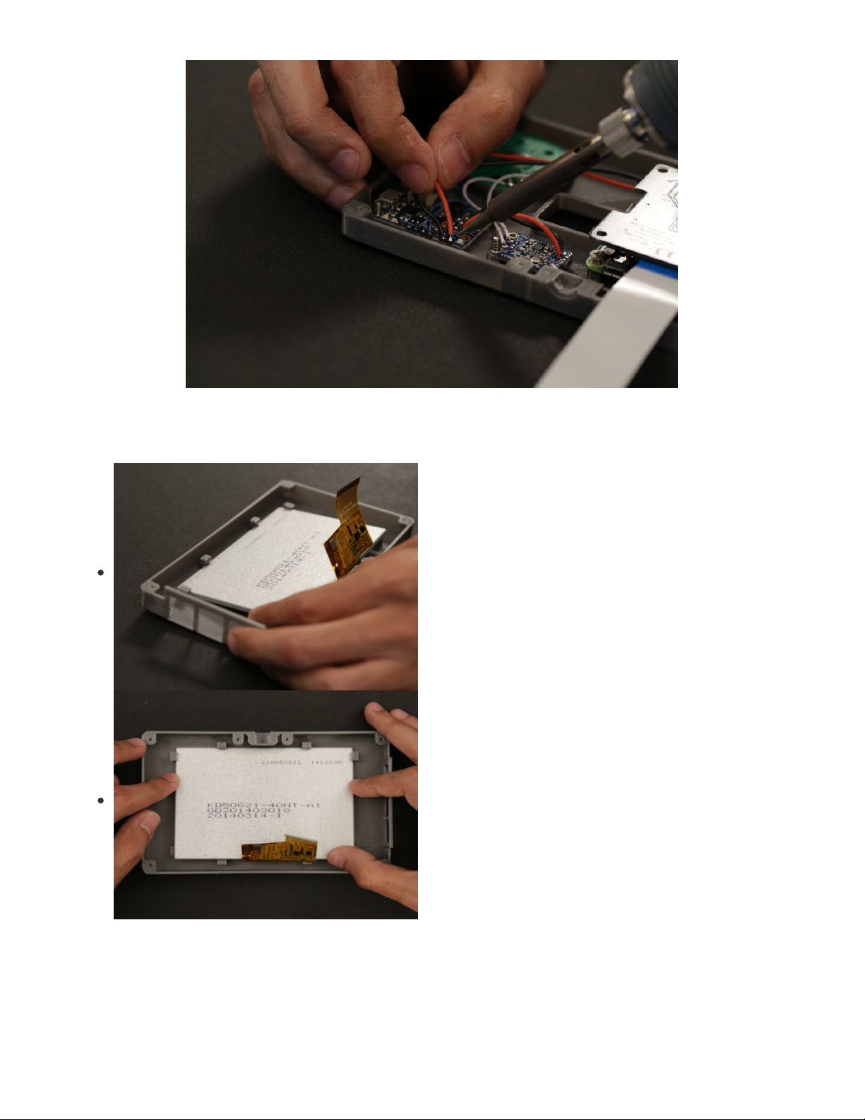
Install Display
Insert the display into the top enclosure part at an angle, with
the corners going into the clips.
© Adafruit Industries https://learn.adafruit.com/portable-kippah-pi Page 44 of 53
Page 45

Mount Display
Careful bend the enclosure back until the clips allow the display panel to fit under the clips. These clips
will hold the TFT panel in place.
Connect Extension to Display
Pop open the latch from the 40-pin extension and insert the 40-pin cable from the display to the extension
board, then close the latch to secure it in place.
© Adafruit Industries https://learn.adafruit.com/portable-kippah-pi Page 45 of 53
Page 46

Connect 40-pin cable to Extension
Open the latch from the other side of the extension and insert the extension cable connected to the
Kippah into the extension board.
Plug in Battery
Connect the JST cable from the lipo battery to the JST connector on the PowerBoost 1000C.
© Adafruit Industries https://learn.adafruit.com/portable-kippah-pi Page 46 of 53
Page 47

Test Circuit
It's a good idea to check your wiring before closing everything up! Power the circuit on with the slide
switch and see if it lights ups.
© Adafruit Industries https://learn.adafruit.com/portable-kippah-pi Page 47 of 53
Page 48

Closing it up
Cable Management
The wiring should be pretty tight, with the exception of the 40-pin FPC cable. You’ll need to fold this cable
and make sure it stays inside the case while closing it up.
Ports
Insert the ports on the Raspberry Pi into the cut outs on the top half of the enclosure. If you find the
cutouts too tight, you can open them up with a filing tool.
Fasten Shut
Insert #2-56 3/8 flat phillips machine screws into the six counter bores on the bottom of the enclosure.
Hold the two half together while fastening the screws. Fasten them in until you feel they’re completely
joined.
© Adafruit Industries https://learn.adafruit.com/portable-kippah-pi Page 48 of 53
Page 49
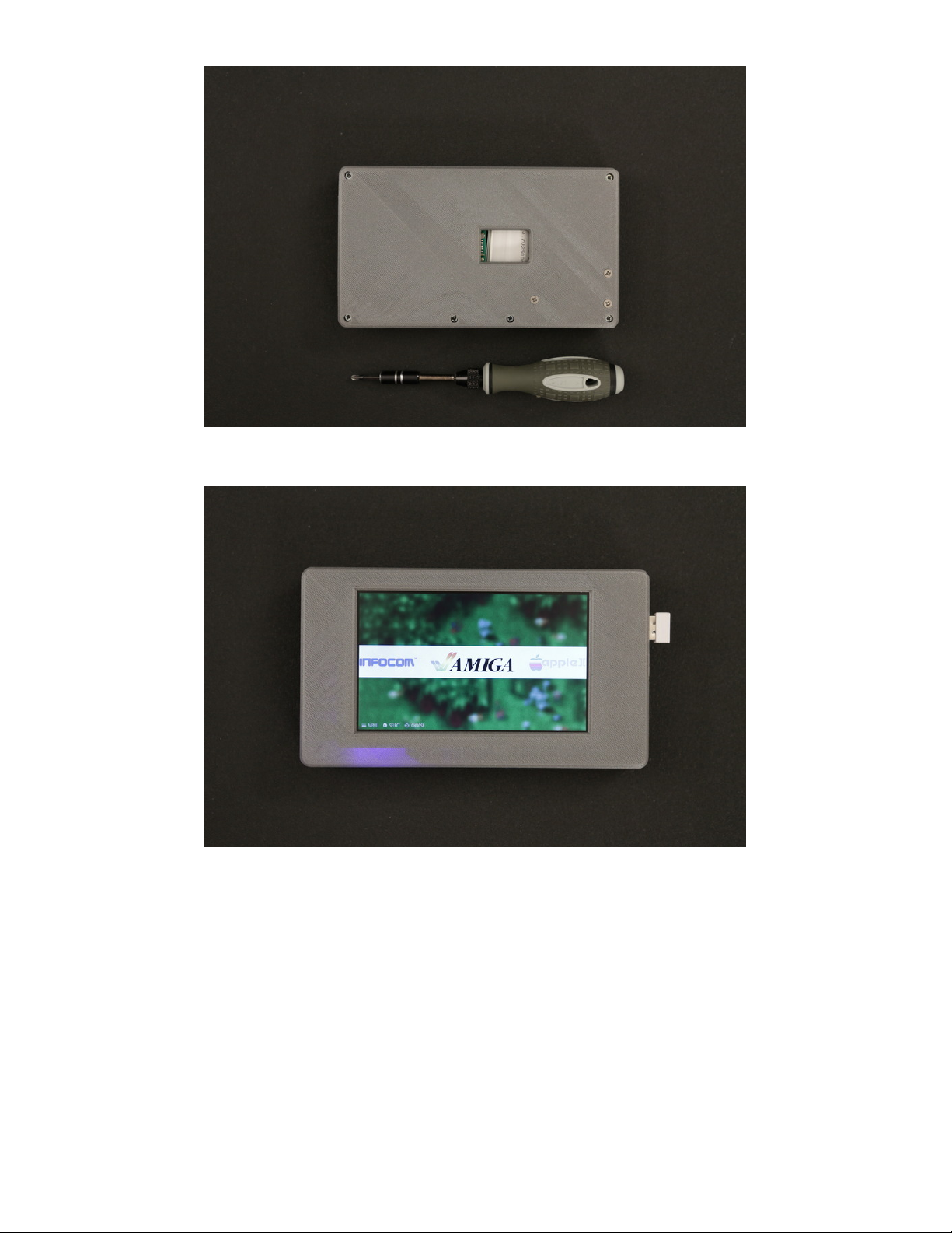
Closed Up
The enclosure is now secured shut!
Portable Kippah Pi
This build is pretty much done! You can optionally insert a tripod screw thread to make it mount to any
standard tripod.
© Adafruit Industries https://learn.adafruit.com/portable-kippah-pi Page 49 of 53
Page 50

Tripod Adapter
Insert the tripod screw into the hole and fasten it with a flat
phillips screw driver. Fasten it in until the screw is flush with
the surface of the enclosure.
© Adafruit Industries https://learn.adafruit.com/portable-kippah-pi Page 50 of 53
Page 51

Mountable Pi
This is screw thread is a 1/4" to 3/8" adapter for Tripods.
Use and Commence Pi
Boot up the Pi and hook up your favorite keyboard. The 2500mAh battery should give you about 2 hours
of use, but it'll vary depending on your application.
What's that orange keyboard?
It's from the Raspberry Pi Kano kit (https://adafru.it/ftM).
© Adafruit Industries https://learn.adafruit.com/portable-kippah-pi Page 51 of 53
Page 52

Made This? Let us know!
If you made this project, please post a make on our Thingiverse page (https://adafru.it/foA). It'll let us know
you're awesome and we'll feature it on our 3D Hangout show (https://adafru.it/foB)!
© Adafruit Industries https://learn.adafruit.com/portable-kippah-pi Page 52 of 53
Page 53

© Adafruit Industries Last Updated: 2021-03-07 07:41:10 PM EST Page 53 of 53
 Loading...