

Page 1

Adafruit Voice Bonnet
Created by Kattni Rembor
Last updated on 2021-07-07 03:47:28 PM EDT
Page 2

2
3
7
7
7
8
8
9
9
10
10
10
10
11
13
15
15
17
18
19
19
19
20
21
21
21
22
22
23
23
26
26
26
Guide Contents
Guide Contents
Overview
Pinouts
Power
Sound
Button
STEMMA QT Connector
DotStar LEDs
Digital/Analog Connector
Raspberry Pi Setup
Step 1 - Burn SD Card
Step 2 - Configure log-in access
Step 3 - Log in & Enable Internet
Step 4 - Update/Upgrade
Blinka Setup
Audio Setup
Install Voicecard software
Headphone/Speaker Test
Microphone Test
Python Usage
Joystick and Button
DotStar LEDs
GPIO JST connector
Parts
Wiring
Code
Stemma QT
Parts
Wiring
Code
Downloads
Files:
Schematic and Fab Print
© Adafruit Industries https://learn.adafruit.com/adafruit-voice-bonnet Page 2 of 28
Page 3

Overview
Your Raspberry Pi computer is like an electronic brain - and with the Adafruit Voice Bonnet you can give it
a mouth and ears as well! Featuring two microphones and two 1 Watt speaker outputs using a high quality
I2S codec, this Pi add-on will work with
any Raspberry Pi with a 2x20 connector - from the Pi Zero up to the
Pi 4 and beyond
(basically all but the very first ones made).
© Adafruit Industries https://learn.adafruit.com/adafruit-voice-bonnet Page 3 of 28
Page 4

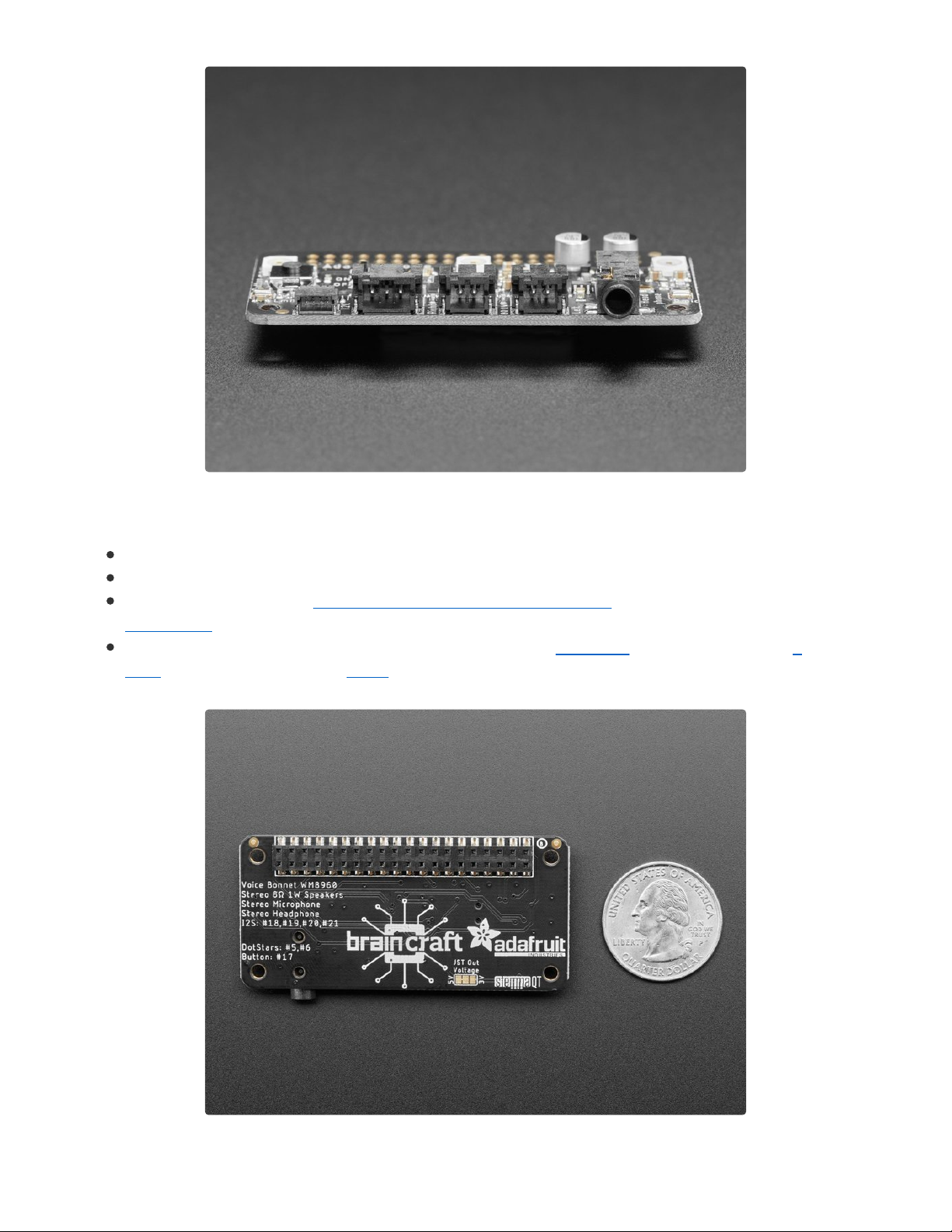
The on-board WM8960 codec uses I2S digital audio for great quality recording and
playback (https://adafru.it/Of7) - so it sounds a lot better than the headphone jack on the Pi (or the no-
headphone jack on a Pi Zero). We put ferrite beads and filter capacitors on every input and output to get
the best possible performance, and all at a great price.
We specifically designed this bonnet for use with making machine learning projects such as DIY voice
assistants - for example see this guide on creating a DIY Google Assistant (https://adafru.it/Of8). But you
could do various voice activated or voice recognition projects. With two microphones, basic voice position
can be detected as well.
WM8960 codec uses I2S digital audio for both input and output (https://adafru.it/Of7)
On/Off privacy switch to deactivate audio so you
know
it can't be recording.
Two analog microphone inputs (left and right)
Two 1W speaker outputs
3.5mm stereo headphone or line-out audio
Plugs into any Raspberry Pi with 2x20 headers
© Adafruit Industries https://learn.adafruit.com/adafruit-voice-bonnet Page 4 of 28
Page 5
With the extra space on the PCB we also added some bonus extras!
Push button - Use to change modes, activate the voice assistant, anything you like!
Three DotStar RGB LEDs - add LED feedback or make a rainbow light show
STEMMA QT connector - plug in any of our I2C sensors, OLEDs, or
accessories (https://adafru.it/HMB).
3 Pin JST STEMMA connector - for larger accessories, like NeoPixels (https://adafru.it/Cup), a
relay (https://adafru.it/NmC) or servo (https://adafru.it/FWq)
© Adafruit Industries https://learn.adafruit.com/adafruit-voice-bonnet Page 5 of 28
Page 6

No assembly required! Simply pop it onto your Pi and install the microphone/speaker card using our
installer script. Your Pi will then have stereo input and output for use in any software - they appear as any
other speaker/mic would. Play music or record audio with ease. For audio input, the two microphones are
built into the Bonnet. For audio output, you can either use the Line-out/Headphone 3.5mm stereo jack
or
you can plug in one or two of our enclosed speakers (https://adafru.it/uyB). For DIY speakers, solder any
1W+ speaker to one of these JST 2-PH cables (https://adafru.it/drM). If you'd like to stack another HAT or
bonnet on top, use a 2x20 stacking header (https://adafru.it/ejT) to feed through the 2x20 connector.
© Adafruit Industries https://learn.adafruit.com/adafruit-voice-bonnet Page 6 of 28
Page 7

Pinouts
Power
5.0V - Connected to power on the audio amp
3.3V - Connected to the STEMMA QT / Qwiic connector
GND - Ground for everything
Sound
© Adafruit Industries https://learn.adafruit.com/adafruit-voice-bonnet Page 7 of 28
Page 8

GPIO #18, GPIO#19, GPIO #20, GPIO #21 - I2S
Digital Audio.
Speakers - The two speaker connectors are located
on the bottom in the middle, labeled Right and Left.
Plug in an enclosed speaker (https://adafru.it/uyB) or
use a JST 2PH cable to attach custom
speakers (https://adafru.it/drM).
Microphones - The two mics are in the middle of
each side, labeled L Mic and R Mic.
Headphones/Line Out - 3.5mm headphone jack
located on the bottom right. Use any headphones or
Line-Out to another audio system.
On/Off Switch - Located towards the left in the
middle of the board, switches audio on and off.
Button
This pin has a 10K pullup to 3.3V so when the button is
pressed, you will read a LOW voltage on this pin.
GPIO#17 - Button
STEMMA QT Connector
SCL, SDA - I2C data for the STEMMA QT / Qwiic
connector. Can also use with Grove sensors with an
adapter cable (https://adafru.it/Ndk). Great for quickly
adding sensors or accessories with plug-and-play.
© Adafruit Industries https://learn.adafruit.com/adafruit-voice-bonnet Page 8 of 28
Page 9

DotStar LEDs
Three fully color RGB addressable LEDs can provide
feedback or a light show. Uses DotStar protocol (not
NeoPixel) so any microcomputer can easily control the
lights.
GPIO #5 - DotStar LED data pin.
GPIO #6 - Dotstar LED clock pin.
Digital/Analog Connector
GPIO#12 - 3-pin JST digital or analog connector. Easily
connect things like NeoPixels (https://adafru.it/Cup) or
servos (https://adafru.it/FWq) using this 2mm connector.
You can also use a generic JST cable to connect to a
breadboard. (https://adafru.it/CVg)
© Adafruit Industries https://learn.adafruit.com/adafruit-voice-bonnet Page 9 of 28
Page 10

Raspberry Pi Setup
OK now you have all your parts in order, it's time to get your Raspberry Pi computer set up with the HAT or
Bonnet.
Step 1 - Burn SD Card
Use Etcher or the Raspberry Pi Imager (https://adafru.it/dDL) to burn the latest Raspbian Lite to an SD card
(you can use full but we won't be using the desktop software and it takes up a bunch of room.
Step 2 - Configure log-in access
You'll need to be able to log into your Pi, either enable SSH access (and use and Ethernet
cable) (https://adafru.it/jvB), use a USB to serial cable, or connect a monitor and keyboard. Basically get it
so you can log in.
We have a quickstart guide here (https://adafru.it/NmF) and here that you can follow (https://adafru.it/DQA),
or there's dozens of online guides. it is assumed by the next step you are able to log in and type
commands in - ideally from a desktop computer, so you can copy and paste in some of the very long
commands!
Step 3 - Log in & Enable Internet
Once you've logged in, enable WiFi (if you have built in WiFi) with sudo raspi-config (https://adafru.it/v7D)
so you can ssh in.
© Adafruit Industries https://learn.adafruit.com/adafruit-voice-bonnet Page 10 of 28
Page 11
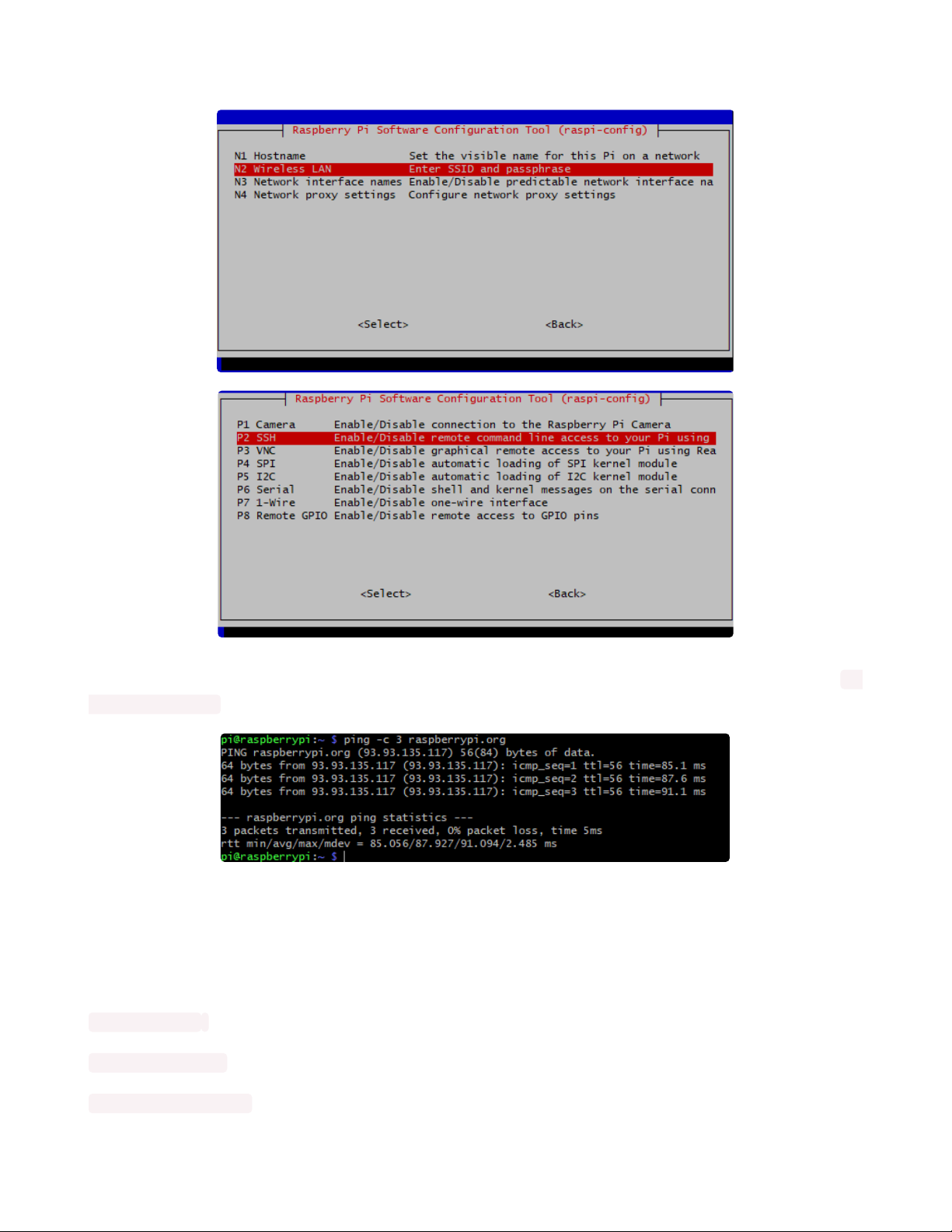
Enable SSH as well if you haven't yet, also via sudo raspi-config
After you're done, reboot, and verify you can log into your Pi and that it has internet access by running ping
-c 3 raspberrypi.org and seeing successful responses.
Step 4 - Update/Upgrade
Now that you are logged in, perform an update/update:
sudo apt update
sudo apt-get update
sudo apt-get -y upgrade
© Adafruit Industries https://learn.adafruit.com/adafruit-voice-bonnet Page 11 of 28
Page 12

and
sudo apt-get install -y python3-pip
sudo pip3 install --upgrade setuptools
OK you've now got a nice, clean, connected, and up-to-date Pi!
© Adafruit Industries https://learn.adafruit.com/adafruit-voice-bonnet Page 12 of 28
Page 13

Blinka Setup
Blinka is our CircuitPython library compatibility layer. It allows many of the libraries that were written for
CircuitPython to run on CPython for Linux. To learn more about Blinka, you can check out our
CircuitPython on Linux and Raspberry Pi (https://adafru.it/BSN) guide.
We put together a script to easily make sure your Pi is correctly configured and install Blinka. It requires
just a few commands to run. Most of it is installing the dependencies.
cd ~
sudo pip3 install --upgrade adafruit-python-shell
wget https://raw.githubusercontent.com/adafruit/Raspberry-Pi-Installer-Scripts/master/raspiblinka.py
sudo python3 raspi-blinka.py
When it asks you if you want to reboot, choose yes.
Finally, once it reboots, there are just a couple CircuitPython libraries to install for the BrainCraft HAT or
Voice Bonnet.
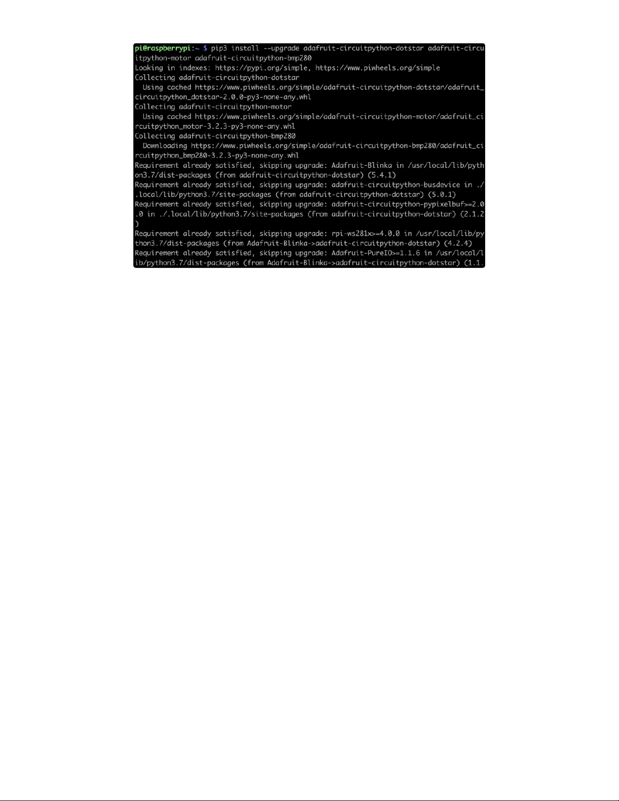
The DotStar library is for controlling the 3 on-board DotStar LEDs and the Motor library is for testing out the
GPIO pins.
pip3 install --upgrade adafruit-circuitpython-dotstar adafruit-circuitpython-motor adafruitcircuitpython-bmp280
© Adafruit Industries https://learn.adafruit.com/adafruit-voice-bonnet Page 13 of 28
Page 14
That's it for Blinka and CircuitPython libraries.
© Adafruit Industries https://learn.adafruit.com/adafruit-voice-bonnet Page 14 of 28
Page 15

Audio Setup
Install Voicecard software
Make sure you've got the BrainCraft HAT or Voice Bonnet installed, and I2C support installed as well!
When you run sudo i2cdetect -y 1
you should see an entry under 1A, indicating the hardware sees the audio card. The number may also
appear as UU if you already installed software
At the command line run:
cd ~
sudo apt-get install -y git
git clone https://github.com/HinTak/seeed-voicecard (https://adafru.it/Nna)
cd seeed-voicecard
Depending on your kernel version, you may need to change your branch. You can check your kernel
version by typing uname -r .
If your kernel version is around 5.4, use the following:
git checkout v5.5
sudo ./install.sh
If your kernel version is 5.10 or higher, use the following:
git checkout v5.9
sudo ./install.sh
Start by making sure you've installed I2C support, see the previous page (Blinka Setup) on how to
do it!
© Adafruit Industries https://learn.adafruit.com/adafruit-voice-bonnet Page 15 of 28
Page 16

At the end you should see something like this:
Reboot with
sudo reboot
and on reboot run
sudo aplay -l
To list all sound cards, you should see it at the bottom
If your card number differs from the above image, take note of your number.
You can use alsamixer to adjust the volume, dont forget to select the card with F6
On a Raspberry Pi 4, your card number may be Card 2 instead of 1 because of the second HDMI
port. You'll need to make some changes to some of the commands to reflect this further down.
© Adafruit Industries https://learn.adafruit.com/adafruit-voice-bonnet Page 16 of 28
Page 17

A gain of about 60% is plenty loud!
Headphone/Speaker Test
Make sure the Audio On/Off switch is set to ON!
With either headphones plugged into the headphone jack or a speaker attached to the speaker port, run
speaker-test -c2
you will hear white noise coming out of the speakers/headphones!
If you don't hear anything, make sure you have the audio on/off switch set!
© Adafruit Industries https://learn.adafruit.com/adafruit-voice-bonnet Page 17 of 28
Page 18

Microphone Test
There are two microphones, and now we can test that they work. This test is best done with headphones ,
not using the speaker port, because it can cause a painful feedback effect if the speakers are next to the
mics!
Run:
sudo arecord -f cd -Dhw:1 | aplay -Dhw:1
If your sound card ID is not #1, then replace the number in both of the -Dhw: parameters with your actual
number.
Then either gently rub each microphone, or speak to hear yourself echoed!
Control-C to quit when done
Your audio subsystem is now completely tested!
© Adafruit Industries https://learn.adafruit.com/adafruit-voice-bonnet Page 18 of 28
Page 19

Python Usage
At this point, you should have just about everything already set up.
Besides the audio, the Voice Bonnet has quite a few other useful features on it that can be controlled
through Python. We'll go through those and how to control them in Python.
Joystick and Button
The button uses simple digitalio , so it's really simple to
control. Here's a little script that will setup the GPIO,
create an internal pull up, and then print out the value to
the terminal.
import time
import board
from digitalio import DigitalInOut, Direction, Pull
button = DigitalInOut(board.D17)
button.direction = Direction.INPUT
button.pull = Pull.UP
while True:
if not button.value:
print("Button pressed")
time.sleep(0.01)
Go ahead and save the above code onto your Pi as button_test.py and run it with the following command:
python button_test.py
Now try moving the joystick and press the button and you should see it print out what you're pressing.
DotStar LEDs
© Adafruit Industries https://learn.adafruit.com/adafruit-voice-bonnet Page 19 of 28
Page 20

The 3 DotStar LEDS can be controlled with the DotStar
CircuitPython Library. Here's a little script that will setup
the DotStar LEDs and then color cycle them.
import time
import board
import adafruit_dotstar
DOTSTAR_DATA = board.D5
DOTSTAR_CLOCK = board.D6
dots = adafruit_dotstar.DotStar(DOTSTAR_CLOCK, DOTSTAR_DATA, 3, brightness=0.2)
def wheel(pos):
# Input a value 0 to 255 to get a color value.
# The colours are a transition r - g - b - back to r.
if pos < 0 or pos > 255:
return (0, 0, 0)
if pos < 85:
return (255 - pos * 3, pos * 3, 0)
if pos < 170:
pos -= 85
return (0, 255 - pos * 3, pos * 3)
pos -= 170
return (pos * 3, 0, 255 - pos * 3)
while True:
for j in range(255):
for i in range(3):
rc_index = (i * 256 // 3) + j * 5
dots[i] = wheel(rc_index & 255)
dots.show()
time.sleep(0.01)
Go ahead and save the above code onto your Pi as dotstar_test.py and run it with the following command:
python dotstar_test.py
The DotStar LEDs should start color-cycling in a rainbow.
GPIO JST connector
© Adafruit Industries https://learn.adafruit.com/adafruit-voice-bonnet Page 20 of 28
Page 21

GPIO 12 is accessible with the JST connector on the
bottom edge of the Voice Bonnet.
Parts
For this script, we'll just need one part that isn't included with the Voice Bonnet:
Micro Servo with 3-pin JST Cable - STEMMA Connector Compatible
This tiny little servo can rotate approximately 180 degrees (90 in each direction), and works just like the standard kinds you're used to
but smaller. You can use any...
$5.95
In Stock
Wiring
Connect the JST PH 3-pin plug into the GPIO #12 on
the Voice Bonnet
https://adafru.it/Ofe
Code
Add to Cart
https://adafru.it/Ofe
© Adafruit Industries https://learn.adafruit.com/adafruit-voice-bonnet Page 21 of 28
Page 22

import time
import board
import pulseio
from adafruit_motor import servo
SERVO_PIN = board.D12
pwm = pulseio.PWMOut(SERVO_PIN, frequency=50)
servo = servo.Servo(pwm, min_pulse=750, max_pulse=2250)
while True:
for angle in range(0, 180, 5): # 0 - 180 degrees, 5 degrees at a time.
servo.angle = angle
time.sleep(0.05)
for angle in range(180, 0, -5): # 180 - 0 degrees, 5 degrees at a time.
servo.angle = angle
time.sleep(0.05)
Go ahead and save the above code onto your Pi as servo_test.py and run it with the following command:
python servo_test.py
The servo should start sweeping back and forth in 5 degree increments.
Stemma QT
For the Stemma QT port, you can use any of our 50+
sensors, but we're going to use a script that demonstrates
using the BMP280 because it's so simple.
Parts
For this script, we'll just need a BMP280 and a Stemma QT cable:
Adafruit BMP280 I2C or SPI Barometric Pressure & Altitude Sensor
Bosch has stepped up their game with their new BMP280 sensor, an environmental sensor with temperature, barometric pressure that is
the next generation upgrade to the...
$9.95
In Stock
Add to Cart
© Adafruit Industries https://learn.adafruit.com/adafruit-voice-bonnet Page 22 of 28
Page 23

STEMMA QT / Qwiic JST SH 4-pin Cable - 100mm Long
This 4-wire cable is a little over 100mm / 4" long and fitted with JST-SH female 4-pin connectors on both ends. Compared with the
chunkier JST-PH these are 1mm pitch instead of...
$0.95
In Stock
Wiring
Connect one side of the Stemma QT cable to either
port on the BMP280
Connect the other side to the Stemma QT port on
the Voice Bonnet
https://adafru.it/Off
Code
Add to Cart
https://adafru.it/Off
© Adafruit Industries https://learn.adafruit.com/adafruit-voice-bonnet Page 23 of 28
Page 24

# SPDX-FileCopyrightText: 2021 ladyada for Adafruit Industries
# SPDX-License-Identifier: MIT
"""Simpletest Example that shows how to get temperature,
pressure, and altitude readings from a BMP280"""
import time
import board
# import digitalio # For use with SPI
import adafruit_bmp280
# Create sensor object, communicating over the board's default I2C bus
i2c = board.I2C() # uses board.SCL and board.SDA
bmp280 = adafruit_bmp280.Adafruit_BMP280_I2C(i2c)
# OR Create sensor object, communicating over the board's default SPI bus
# spi = board.SPI()
# bmp_cs = digitalio.DigitalInOut(board.D10)
# bmp280 = adafruit_bmp280.Adafruit_BMP280_SPI(spi, bmp_cs)
# change this to match the location's pressure (hPa) at sea level
bmp280.sea_level_pressure = 1013.25
while True:
print("\nTemperature: %0.1f C" % bmp280.temperature)
print("Pressure: %0.1f hPa" % bmp280.pressure)
print("Altitude = %0.2f meters" % bmp280.altitude)
time.sleep(2)
Go ahead and save the above code onto your Pi as bmp280_simpletest.py and run it with the following
command:
python bmp280_simpletest.py
The terminal should start printing out the detected measurements.
© Adafruit Industries https://learn.adafruit.com/adafruit-voice-bonnet Page 24 of 28
Page 25

© Adafruit Industries https://learn.adafruit.com/adafruit-voice-bonnet Page 25 of 28
Page 26

Downloads
Files:
WM8960 datasheet (https://adafru.it/Of9)
EagleCAD files on GitHub (https://adafru.it/Ofa)
Fritzing object in the Adafruit Fritzing Library (https://adafru.it/Ofb)
Schematic and Fab Print
© Adafruit Industries https://learn.adafruit.com/adafruit-voice-bonnet Page 26 of 28
Page 27

© Adafruit Industries https://learn.adafruit.com/adafruit-voice-bonnet Page 27 of 28
Page 28

© Adafruit Industries Last Updated: 2021-07-07 03:47:28 PM EDT Page 28 of 28
 Loading...