


Adafruit LED Arcade Button 1x4 STEMMA
QT
Created by Kattni Rembor
https://learn.adafruit.com/adafruit-led-arcade-button-qt
Last updated on 2022-02-04 12:06:33 PM EST
©Adafruit Industries Page 1 of 21

Table of Contents
Overview
Pinouts
• Switch Connectors
• LED Connectors
• STEMMA QT Connectors
• ATTiny817 seesaw Microcontroller
• Address Jumpers
• Through-Hole Pads
• Power LED and Jumper
Python & CircuitPython
• CircuitPython Microcontroller Wiring
• Python Computer Wiring
• Python Installation of seesaw Library
• CircuitPython & Python Usage
• Multi-Board Example
Python Docs
Arduino
• I2C Wiring
• Library Installation
• Load Arcade QT Example
3
6
7
7
8
8
8
10
11
11
11
12
13
13
15
17
17
17
18
18
Arduino Docs
Downloads
• Files:
• Schematic and Fab Print
20
20
20
21
©Adafruit Industries Page 2 of 21

Overview
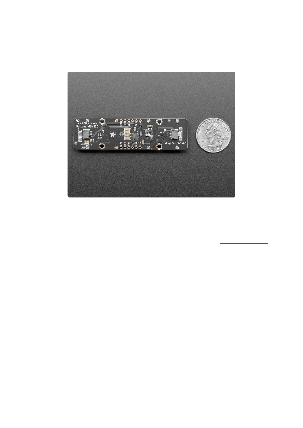
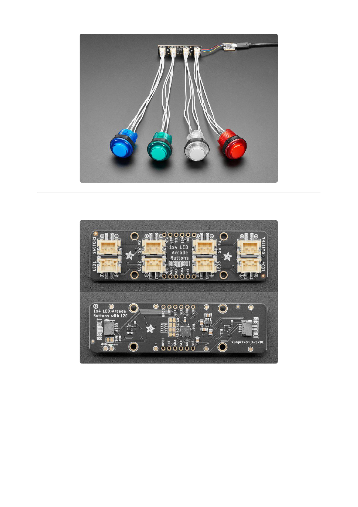
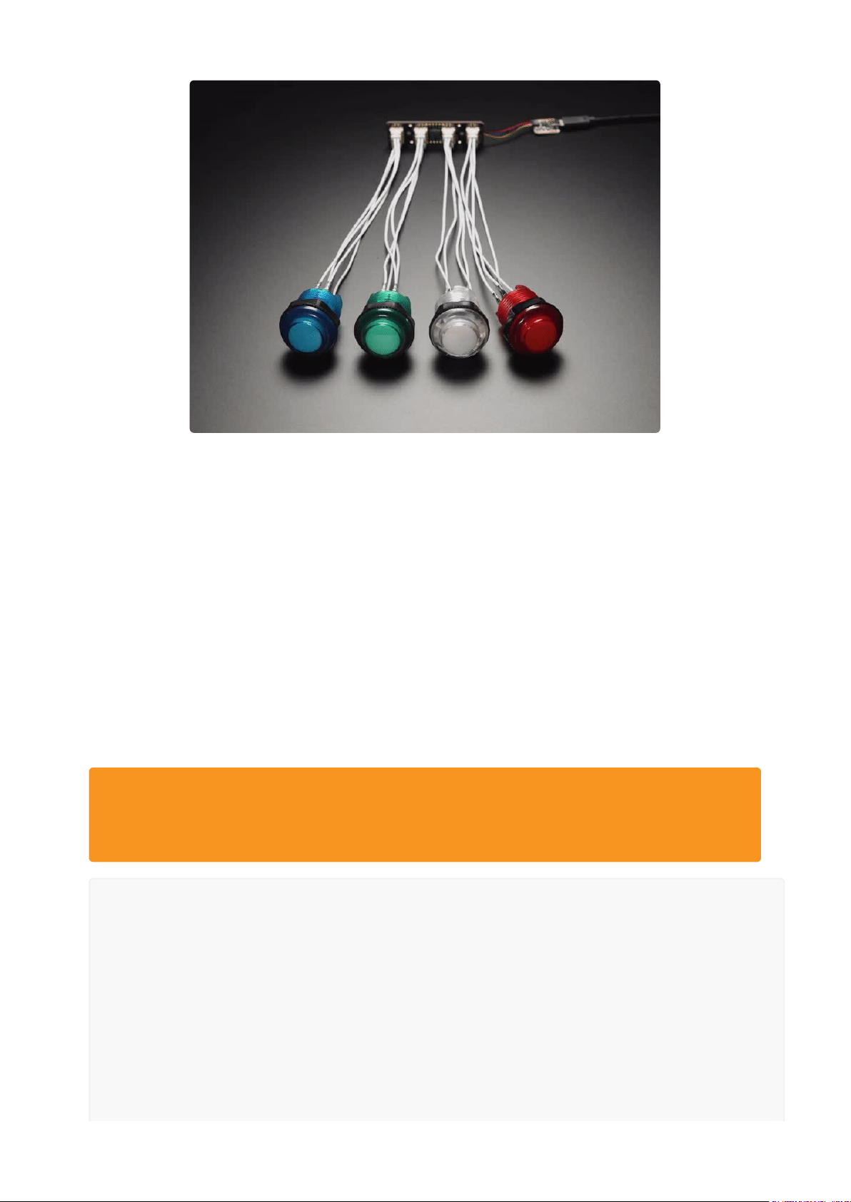
The only thing better than a glowy arcade button is, perhaps, FOUR glowing arcade
buttons - and that's what theAdafruit LED Arcade Button 1x4 QT I2C Breakoutwill let
you do! This long 3" x 0.8" PCB has 8 x JST XH sockets that will fit our arcade button
quick connects(https://adafru.it/Yd5). Each XH pair lets you connect one arcade
button that has a built in LED illuminator, and makes it easy to use with a breadboard/
perfboard or with a STEMMA QT (Qwiic) connector for instant I2C connectivity on any
platform.
©Adafruit Industries Page 3 of 21
Please note,each order comes with one assembled and programmed PCB but no LED
arcade buttons(https://adafru.it/Yd6) or JST XH quick connect cables(https://adafru.it
/Yd5). We have a wide range of colors and sizes, so pick your favs to go along, this is
just the controller board that plugs into a microcontroller.
A built-in microcontroller is pre-programmed with our seesaw firmware so button
presses and LED PWM controlling is done all over I2C. You can even connect multiple
board by chaining the I2C and cutting open the I2C address jumpers - with four
jumpers you can have up to 16 of these boards on a single I2C bus. We have Arduino(
https://adafru.it/BrV) and CircuitPython/Python libraries(https://adafru.it/BrW) for
controlling the Arcade 1x4's so you can use any microcontroller/computer for quick
creation of glowy button interfaces, without setting up PWM outputs. We found that
many LEDs in buttons really want 5V power to light up, and are dim or dark at 3.3V, so
we added a small boost converter to let you light up at 5V even if the microcontroller
you are using is 3V power.
©Adafruit Industries Page 4 of 21
You can also fit the breakouts onto a breadboard if you like - with two sets of
breakout pads, there's plenty of flexibility for any kind of use. There are two rows of 6-
pin contacts on a 0.1" grid on both sides. Solder in both sides for mechanical stability.
Soldering is required to attach the header for breadboard use, if you have STEMMA
QT/Qwiic connectors its a simple plug-in to get working. A microcontroller is required
to drive this board, it isn't stand-alone. LED arcade buttons(https://adafru.it/Yd6) and J
ST XH quick connect cables(https://adafru.it/Yd5) not included!
©Adafruit Industries Page 5 of 21
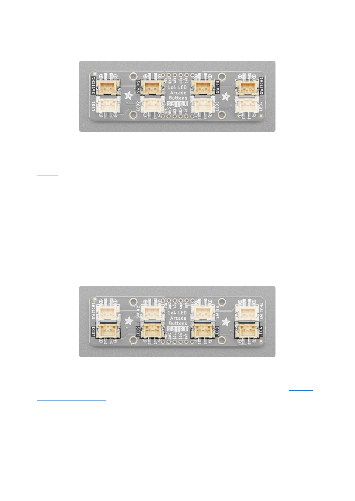
Pinouts
The Arcade QT is full of fun features. Here's a detailed look!
©Adafruit Industries Page 6 of 21
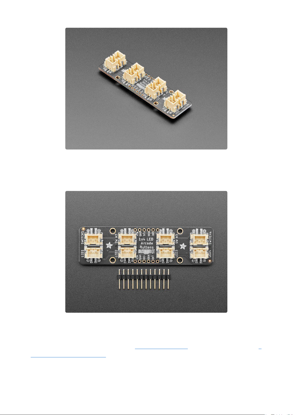
Switch Connectors
Spread out along the board are four two-pin JST XH switch connectors. They are
labeled as SWITCH1, SW #2, SW #3, and SWITCH4. Using the JST XH quick connect
cables(https://adafru.it/Yd5), you can easily connect four arcade button switches to
this board. The switches are on the following pins on the board's seesaw
microcontroller:
SWITCH1 is on pin 18.
•
SW #2 is on pin 19.
•
SW #3 is is on pin 20.
•
SWITCH4 is on pin 2.
•
LED Connectors
Spread out along the board, opposite the switch connectors, are four two-pin JST XH
LED connectors. They are labeled as LED1, LED2, LED3, and LED4. Using the JST XH
quick connect cables(https://adafru.it/Yd5), you can easily connect four arcade button
LEDs to this board. The LED connectors are on the following pins on the board's
seesaw microcontroller:
LED1 is on pin 12.
•
LED2 is on pin 13.
•
LED3 is is on pin 0.
•
©Adafruit Industries Page 7 of 21

LED4 is on pin 1.
•
STEMMA QT Connectors
On the bottom of the board, near each end, are two STEMMA QT connectors. These
allow you to connect to development boards with STEMMA QT(https://adafru.it/Ft4)
connectors or to other breakouts(https://adafru.it/Qgf) using various associated
accessories(https://adafru.it/Ft6).
ATTiny817 seesaw Microcontroller
The Arcade QT breakout uses an ATtiny817 microcontroller to take I2C commands
and converts them to digital or PWM signals.
Address Jumpers
©Adafruit Industries Page 8 of 21

In the center of the back of the board are four address jumpers. These jumpers allow
you to chain up to 16 of these boards on the same pair of I2C clock and data pins. To
do so, you cut the traces between the the two pads.
The default I2C address is 0x3A. The other address options can be calculated by
“adding” the A0/A1/A2/A3 to the base of 0x3A.
A0 sets the lowest bit with a value of 1, A1 sets the next bit with a value of 2, A2 sets
the next bit with a value of 4, and A3 sets the high bit with a value of 8. The final
address is 0x3A + A3 + A2 + A1 + A0 which would be 0x49.
•
If only A0 is cut, the address is 0x3A + 1 = 0x3B
•
If only A1 is cut, the address is 0x3A + 2 = 0x3C
•
If only A2 is cut, the address is 0x3A + 4 = 0x3E
If only A3 is cut, the address is 0x3A + 8 = 0x42
•
So for example if A2 is cut and A0 is cut, the address is 0x3A + 4 + 1 = 0x3F.
The table below shows all possible addresses, and whether the pin should be high
(cut) or low (closed).
©Adafruit Industries Page 9 of 21

Through-Hole Pads
In the center of the board, on each edge, are a set of six through-hole pads for use
with header pins and a solderless breadboard. They are labeled on the top and the
bottom of the board for easy identification.
When viewed from the of the top of the board:
VIN - This is the power pin. Since the chip can use 3 or 5 VDC. To power the
•
board, give it the same power as the logic level of your microcontroller - e.g. for
a 5V microcontroller like Arduino, use 5V.
GND - This is theground pin. It is the common ground for power and logic.
•
SCL - This is the I2C clock pin. Connect to your microcontroller I2C clock line.
•
This pin can use 3-5V logic, and there's a 10K pullup on this pin to VIN.
SDA - This is the I2C data pin. Connect to your microcontroller I2C data line.
•
This pin can use 3-5V logic, and there's a 10K pullup on this pin to VIN.
INT - This is the interrupt pin. The Seesaw allows for setting GPIO interrupts.
•
This pin will go low when a button is pressed.
UPDI - This is the single-pin Unified Program and Debug Interface for the
•
ATtiny817. This pin is for external programming or on-chip-debugging.
If you're going to use a solderless breadboard with the Arcade QT breakout, you
should solder headers to both sides of the breakout for stability.
©Adafruit Industries Page 10 of 21
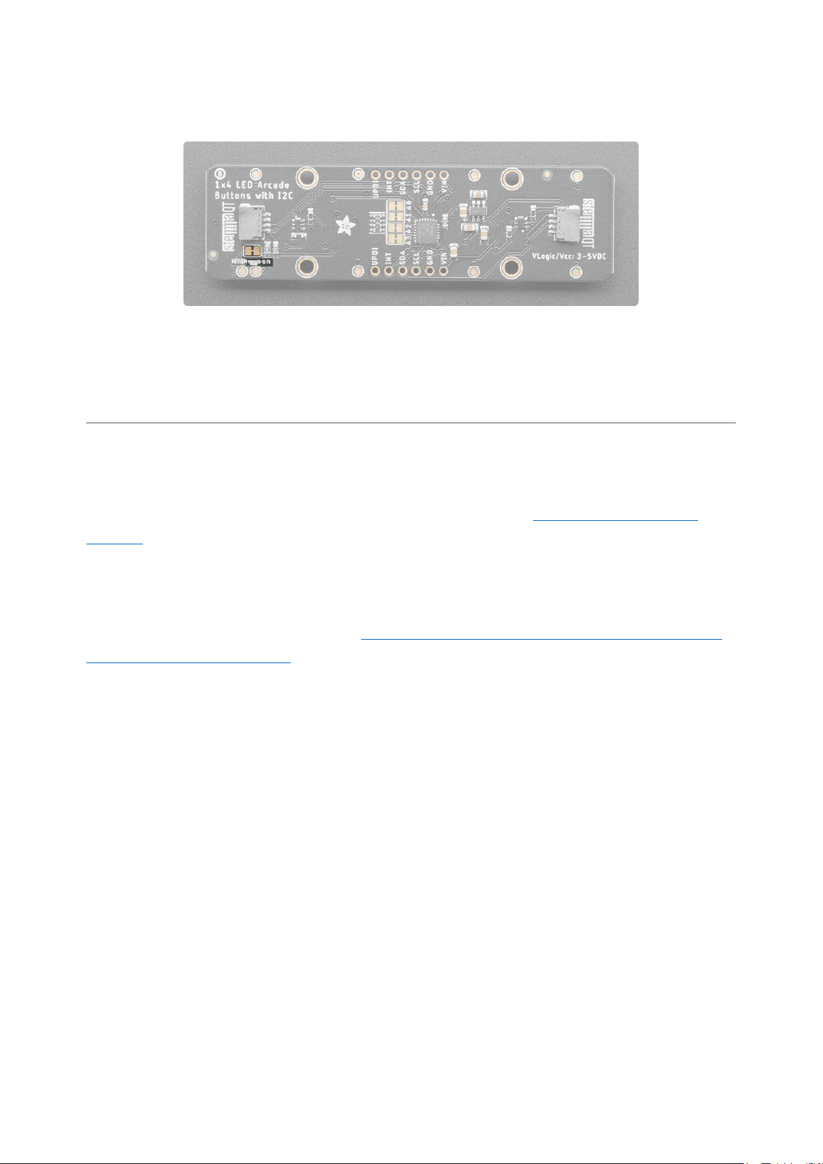
Power LED and Jumper
In the lower left corner, on the back of the board, is the power LED, labeled on. To the
left of the LED is the power LED jumper pad, which defaults to closed. Cut the trace to
disable the power LED. Once cut, you can solder it closed again to enable the LED.
Python & CircuitPython
It's easy to use the Arcade QT with CircuitPython using the Adafruit CircuitPython
seesaw(https://adafru.it/BrW) library. It allows you to write Python code to read the
arcade button presses and control the LEDs.
You can use the Arcade QT with any CircuitPython microcontroller board or with a
computer that has GPIO and Python thanks to Adafruit_Blinka, our CircuitPython-for-
Python compatibility library(https://adafru.it/BSN).
CircuitPython Microcontroller Wiring
First wire up a Arcade QT breakout to your board exactly as follows. The following is
the breakout wired to a QT Py RP2040 using the STEMMA connector:
Board 3Vtobreakout VIN (red wire)
•
Board GNDtobreakout GND (black
•
wire)
Board SCLtobreakout SCL (yellow
•
wire)
Board SDAtobreakout SDA (blue
•
wire)
©Adafruit Industries Page 11 of 21

The following is the breakout wired to a QT Py RP2040 using a solderless
breadboard:
Board 3Vtobreakout VIN (red wire)
•
Board GNDtobreakout GND (black
•
wire)
Board SCLtobreakout SCL (yellow
•
wire)
Board SDAtobreakout SDA (blue
•
wire)
Python Computer Wiring
Since there'sdozensof Linux computers/boards you can use we will show wiring for
Raspberry Pi. For other platforms,please visit the guide for CircuitPython on Linux to
see whether your platform is supported(https://adafru.it/BSN).
Here's the Raspberry Pi wired with I2C using the STEMMA connector:
Pi 3Vto breakout VIN (red wire)
•
Pi GNDto breakout GND (black
•
wire)
Pi SCLtobreakout SCL (yellow
•
wire)
Pi SDAtobreakout SDA (blue wire)
•
Here's the Raspberry Pi wired with I2C using a solderless breadboard:
©Adafruit Industries Page 12 of 21

Pi 3Vto breakout VIN (red wire)
•
Pi GNDto breakout GND (black
•
wire)
Pi SCLtobreakout SCL (yellow
•
wire)
Pi SDAtobreakout SDA (blue wire)
•
Python Installation of seesaw Library
You'll need to install the Adafruit_Blinka library that provides the CircuitPython
support in Python. This may also require enabling I2C on your platform and verifying
you are running Python 3.Since each platform is a little different, and Linux changes
often, please visit the CircuitPython on Linux guide to get your computer ready(https
://adafru.it/BSN)!
Once that's done, from your command line run the following command:
pip3 install adafruit-circuitpython-seesaw
•
If your default Python is version 3 you may need to run pip instead. Just make sure
you aren't trying to use CircuitPython on Python 2.x, it isn't supported!
CircuitPython & Python Usage
To demonstrate using this breakout with CircuitPython, you'll install the necessary
libraries, update your code, and then connect to the serial console(https://adafru.it/
Bec) to see the information printed out.
To use the Arcade QT breakout with CircuitPython, you need to first install the seesaw
library, and its dependencies, into the lib folder on your CIRCUITPY drive.
Then you need to update code.py.
©Adafruit Industries Page 13 of 21

Click the Download Project Bundle button below to download the necessary libraries
and the code.py file in a zip file. Extract the contents of the zip file, and copy the entir
e lib folder and the code.py file to your CIRCUITPY drive.
# SPDX-FileCopyrightText: 2022 Kattni Rembor for Adafruit Industries
# SPDX-License-Identifier: MIT
"""Arcade QT example that pulses the button LED on button press"""
import time
import board
import digitalio
from adafruit_seesaw.seesaw import Seesaw
from adafruit_seesaw.digitalio import DigitalIO
from adafruit_seesaw.pwmout import PWMOut
# The delay on the PWM cycles. Increase to slow down the LED pulsing, decrease to
speed it up.
delay = 0.01
# For most boards.
i2c = board.I2C()
# For the QT Py RP2040, QT Py ESP32-S2, other boards that have SCL1/SDA1 as the
STEMMA QT port.
# import busio
# i2c = busio.I2C(board.SCL1, board.SDA1)
arcade_qt = Seesaw(i2c, addr=0x3A)
# Button pins in order (1, 2, 3, 4)
button_pins = (18, 19, 20, 2)
buttons = []
for button_pin in button_pins:
button = DigitalIO(arcade_qt, button_pin)
button.direction = digitalio.Direction.INPUT
button.pull = digitalio.Pull.UP
buttons.append(button)
# LED pins in order (1, 2, 3, 4)
led_pins = (12, 13, 0, 1)
leds = []
for led_pin in led_pins:
led = PWMOut(arcade_qt, led_pin)
leds.append(led)
while True:
for led_number, button in enumerate(buttons):
if not button.value:
for cycle in range(0, 65535, 8000):
leds[led_number].duty_cycle = cycle
time.sleep(delay)
for cycle in range(65534, 0, -8000):
leds[led_number].duty_cycle = cycle
time.sleep(delay)
Use the commented out code for I2C setup if using a QT Py RP2040.
Now, press and hold the buttons to see the LED pulse.
©Adafruit Industries Page 14 of 21
That's all there is to using the Arcade QT with CircuitPython and the seesaw library!
Multi-Board Example
The following is an example of using two boards at the same time.
First,you need to update code.py.
Click the Download Project Bundle button below to download the necessary libraries
and the code.py file in a zip file. Extract the contents of the zip file, and copy the entir
e lib folder and the code.py file to your CIRCUITPY drive.
To use multiple boards, you must alter the address jumpers on the back to
change the I2C address on the additional boards. For this example, you must cut
the trace on A0.
# SPDX-FileCopyrightText: 2022 Kattni Rembor for Adafruit Industries
# SPDX-License-Identifier: MIT
"""Arcade QT example for multiple boards that turns on button LED when button is
pressed"""
import board
import digitalio
from adafruit_seesaw.seesaw import Seesaw
from adafruit_seesaw.digitalio import DigitalIO
# For most boards.
i2c = board.I2C()
# For the QT Py RP2040, QT Py ESP32-S2, other boards that have SCL1/SDA1 as the
STEMMA QT port.
# import busio
©Adafruit Industries Page 15 of 21

# i2c = busio.I2C(board.SCL1, board.SDA1)
arcade_qt_one = Seesaw(i2c, addr=0x3A)
arcade_qt_two = Seesaw(i2c, addr=0x3B)
arcade_qts = (arcade_qt_one, arcade_qt_two)
# Button pins in order (1, 2, 3, 4)
button_pins = (18, 19, 20, 2)
buttons = []
for arcade_qt in arcade_qts:
for button_pin in button_pins:
button = DigitalIO(arcade_qt, button_pin)
button.direction = digitalio.Direction.INPUT
button.pull = digitalio.Pull.UP
buttons.append(button)
# LED pins in order (1, 2, 3, 4)
led_pins = (12, 13, 0, 1)
leds = []
for arcade_qt in arcade_qts:
for led_pin in led_pins:
led = DigitalIO(arcade_qt, led_pin)
led.direction = digitalio.Direction.OUTPUT
leds.append(led)
while True:
for led_number, button in enumerate(buttons):
leds[led_number].value = not button.value
Use the commented out code for I2C setup if using a QT Py RP2040.
Press any button to turn on that button's LED.
That's all there is to using multiple Arcade QT boards with CircuitPython!
©Adafruit Industries Page 16 of 21

Python Docs
Python Docs(https://adafru.it/C5y)
Arduino
The Adafruit LED Arcade Button 1x4 STEMMA QT breakout uses a seesaw chip. To
use the Arcade QT with Arduino, you'll use the Adafruit Seesaw library. With the
STEMMA QT connectors, you can easily get started with no soldering necessary!
I2C Wiring
Here is how to wire up the breakout using one of the STEMMA QT(https://adafru.it/
Ft4) connectors. The examples show a Metro but wiring will work the same for an
Arduino or other compatible board.
Connectboard VIN (red wire)
•
toArduino 5Vif you are running a
5V board Arduino (Uno, etc.).If your
board is 3V, connect to that instead.
Connect board GND (black
•
wire)toArduino GND
Connect board SCL (yellow
•
wire)toArduino SCL
Connect board SDA (blue
•
Here is how to wire the breakout to a board using a solderless breadboard. To do this,
you must solder header pins to the breakout.
wire)toArduino SDA
Connectboard VIN (red wire)
•
toArduino 5Vif you are running a
5V board Arduino (Uno, etc.).If your
board is 3V, connect to that instead.
Connect board GND (black
•
wire)toArduino GND
Connect board SCL (yellow
•
wire)toArduino SCL
Connect board SDA (blue
•
©Adafruit Industries Page 17 of 21
wire)toArduino SDA

Library Installation
You can install the Adafruit Seesaw library for Arduino using the Library Manager in
the Arduino IDE.
Click theManage Libraries ... menu item, search for seesaw ,and select theAdafruit s
eesaw library:
When asked to install the Adafruit Seesaw library dependencies, click Install all.
Load Arcade QT Example
Open the following example into the Arduino IDE.
/*
* This example shows how read the potentiometer on the I2C QT Slide Potentiometer
* and make the NeoPixels change too!
*/
#include "Adafruit_seesaw.h"
#include <seesaw_neopixel.h>
#define DEFAULT_I2C_ADDR 0x3A
©Adafruit Industries Page 18 of 21

#define SWITCH1 18 // PA01
#define SWITCH2 19 // PA02
#define SWITCH3 20 // PA03
#define SWITCH4 2 // PA06
#define PWM1 12 // PC00
#define PWM2 13 // PC01
#define PWM3 0 // PA04
#define PWM4 1 // PA05
Adafruit_seesaw ss;
void setup() {
Serial.begin(115200);
while (!Serial) delay(10); // wait until serial port is opened
Serial.println(F("Adafruit PID 5296 I2C QT 4x LED Arcade Buttons test!"));
if (!ss.begin(DEFAULT_I2C_ADDR)) {
Serial.println(F("seesaw not found!"));
while(1) delay(10);
}
uint16_t pid;
uint8_t year, mon, day;
ss.getProdDatecode(&pid, &year, &mon, &day);
Serial.print("seesaw found PID: ");
Serial.print(pid);
Serial.print(" datecode: ");
Serial.print(2000+year); Serial.print("/");
Serial.print(mon); Serial.print("/");
Serial.println(day);
if (pid != 5296) {
Serial.println(F("Wrong seesaw PID"));
while (1) delay(10);
}
Serial.println(F("seesaw started OK!"));
ss.pinMode(SWITCH1, INPUT_PULLUP);
ss.pinMode(SWITCH2, INPUT_PULLUP);
ss.pinMode(SWITCH3, INPUT_PULLUP);
ss.pinMode(SWITCH4, INPUT_PULLUP);
ss.analogWrite(PWM1, 127);
ss.analogWrite(PWM2, 127);
ss.analogWrite(PWM3, 127);
ss.analogWrite(PWM4, 127);
}
uint8_t incr = 0;
void loop() {
if (! ss.digitalRead(SWITCH1)) {
Serial.println("Switch 1 pressed");
ss.analogWrite(PWM1, incr);
incr += 5;
} else {
ss.analogWrite(PWM1, 0);
}
if (! ss.digitalRead(SWITCH2)) {
Serial.println("Switch 2 pressed");
ss.analogWrite(PWM2, incr);
incr += 5;
} else {
ss.analogWrite(PWM2, 0);
©Adafruit Industries Page 19 of 21

}
if (! ss.digitalRead(SWITCH3)) {
Serial.println("Switch 3 pressed");
ss.analogWrite(PWM3, incr);
incr += 5;
} else {
ss.analogWrite(PWM3, 0);
}
if (! ss.digitalRead(SWITCH4)) {
Serial.println("Switch 4 pressed");
ss.analogWrite(PWM4, incr);
incr += 5;
} else {
ss.analogWrite(PWM4, 0);
}
delay(10);
}
Press each button to see that button's LED pulse!
That's all there is to using the Arcade QT with Arduino!
Arduino Docs
Arduino Docs(https://adafru.it/SdQ)
Downloads
Files:
ATtiny817 datasheet(https://adafru.it/VhF)
•
EagleCAD PCB files on GitHub(https://adafru.it/Yes)
•
Fritzing object in the Adafruit Fritzing Library(https://adafru.it/Yet)
•
Firmware running on the seesaw(https://adafru.it/Yeu)
•
©Adafruit Industries Page 20 of 21

Schematic and Fab Print
©Adafruit Industries Page 21 of 21
 Loading...