


Adafruit APDS9960 breakout
Created by Justin Cooper
Last updated on 2020-03-26 04:47:18 PM UTC

Overview
This handy sensor is full of features! Add basic gesture sensing, RGB color sensing, proximity sensing, or ambient light
sensing to your project with the Adafruit APDS9960 Proximity, Light, RGB and Gesture Sensor. When connected to
your microcontroller (running our library code) it can detect simple gestures (left to right, right to left, up to down, down
to up are currently supported), return the amount of red, blue, green, and clear light, or return how close an object is to
the front of the sensor. This device uses an I2C interface so it's easy to wire up and use.
New! We've updated this board to be STEMMA QT compatible. We've now included SparkFun
qwiic (https://adafru.it/Fpw) compatible STEMMA QT (https://adafru.it/Ft4) connectors for the I2C bus so you don't
© Adafruit Industries https://learn.adafruit.com/adafruit-apds9960-breakout Page 3 of 24

even need to solder! Just wire up to your favorite microcontroller or computer with a plug-and-play QT
cable (https://adafru.it/JRA) to light/color/proximity data ASAP.
The APDS9960 from Avago Technologies has an integrated IR LED and driver, along with four directional photodiodes
that sense reflected IR energy from the LED. It's proximity detection feature allows it to measure the distance an object
is from the front of the sensor (up to a few centimeters) with 8 bit resolution.
Since there are four IR sensors, you can measure the changes in light reflectance at each of the cardinal locations over
time and turn those changes into gestures. Our interface library can detect directional gestures (left to right, right to
© Adafruit Industries https://learn.adafruit.com/adafruit-apds9960-breakout Page 4 of 24

left, up to down, down to up), but in theory more complicated gestures like zig-zag, clockwise or counterclockwise
circle, near to far, etc. could also be detected with additional code.
The APDS9960 has a configurable interrupt that can fire when a certain proximity threshold is broken, or when a color
sensor breaks a certain threshold.
For your convenience we've pick-and-placed the sensor on a PCB with a 3.3V regulator and some level shifting so it
can be easily used with your favorite 3.3V or 5V microcontroller.
We've also prepared software libraries to get you up and running in Arduino with just a few lines of code!
© Adafruit Industries https://learn.adafruit.com/adafruit-apds9960-breakout Page 5 of 24

© Adafruit Industries https://learn.adafruit.com/adafruit-apds9960-breakout Page 6 of 24

Pinouts
Power Pins:
Vin - this is the power pin. Since the sensor uses 3.3V, we have included an onboard voltage regulator that will
take 3-5VDC and safely convert it down. To power the board, give it the same power as the logic level of your
microcontroller - e.g. for a 5V micro like Arduino, use 5V
3Vo - this is the 3.3V output from the voltage regulator, you can grab up to 100mA from this if you like
GND - common ground for power and logic
© Adafruit Industries https://learn.adafruit.com/adafruit-apds9960-breakout Page 7 of 24

Logic pins:
SCL - this is the I2C clock pin, connect to your microcontrollers I2C clock line. There is a 10K pullup on this pin
and it is level shifted so you can use 3 - 5VDC.
SDA - this is the I2C data pin, connect to your microcontrollers I2C data line. There is a 10K pullup on this pin and
it is level shifted so you can use 3 - 5VDC.
INT - this is the interrupt-output pin. It is 3V logic and you can use it to detect when a new reading is ready or
when a reading gets too high or too low.
STEMMA QT (https://adafru.it/Ft4) - These connectors allow you to connectors to dev boards with STEMMA QT
connectors or to other things with various associated accessories (https://adafru.it/Ft6)
© Adafruit Industries https://learn.adafruit.com/adafruit-apds9960-breakout Page 8 of 24

Assembly
Prepare the header strip:
Cut the strip to length if necessary. It will be easier to
solder if you insert it into a breadboard - long pins down
© Adafruit Industries https://learn.adafruit.com/adafruit-apds9960-breakout Page 9 of 24

Add the breakout board:
Place the breakout board over the pins so that the short
pins poke through the breakout pads
© Adafruit Industries https://learn.adafruit.com/adafruit-apds9960-breakout Page 10 of 24

And Solder!
Be sure to solder all 6 pins for reliable electrical contact.
(For tips on soldering, be sure to check out our Guide to
Excellent Soldering
(https://adafru.it/aTk)
).
© Adafruit Industries https://learn.adafruit.com/adafruit-apds9960-breakout Page 11 of 24

You're done! Check your solder joints visually and
continue onto the next steps
© Adafruit Industries https://learn.adafruit.com/adafruit-apds9960-breakout Page 12 of 24

Arduino Wiring &
Test
You can easily wire this breakout to any microcontroller, we'll be using an Adafruit Metro (Arduino compatible) with the
Arduino IDE. But, you can use any other kind of microcontroller as well as long as it has I2C clock and I2C data lines.
Note this chip uses address 0x39 and that you cannot change addresses!
I2C Wiring
Connect Vin to the power supply, 3-5V is fine. Use the same voltage that the microcontroller logic is based off of.
For most Arduinos, that is 5V
Connect GND to common power/data ground
Connect the SCL pin to the I2C clock SCL pin on your Arduino.
On an UNO & '328 based Arduino, this is also known as A5, on a Mega it is also known as digital 21 and on a
Leonardo/Micro, digital 3
Connect the SDA pin to the I2C data SDA pin on your Arduino.
On an UNO & '328 based Arduino, this is also known as A4, on a Mega it is also known as digital 20 and on a
Leonardo/Micro, digital 2
https://adafru.it/z0f
https://adafru.it/z0f
© Adafruit Industries https://learn.adafruit.com/adafruit-apds9960-breakout Page 13 of 24

Download Adafruit_APDS9960 library
To begin reading sensor data, you will need to download Adafruit_APDS9960 from the Arduino library manager.
Open up the Arduino library manager:
Search for the Adafruit APDS9960 library and install it
We also have a great tutorial on Arduino library installation at:
http://learn.adafruit.com/adafruit-all-about-arduino-libraries-install-use (https://adafru.it/aYM)
Load Gesture Sensor Example
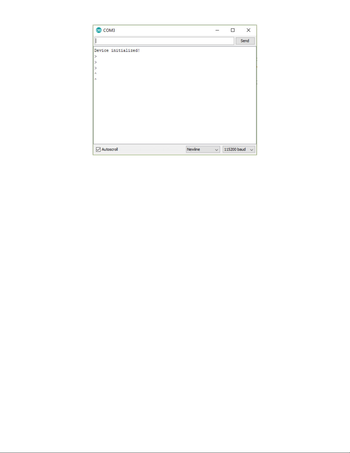
Open up File->Examples->Adafruit_APDS9960->gesture_sensor and upload the code to your microcontroller wired up
to the sensor. This example connects to the sensor and starts interpreting gestures.
Once uploaded to your Adruino, open up the serial console at 115200 baud speed. Put your hand close to the front of
the sensor to activate gesture mode. Then make your directional gestures 3 or 4 inches from the sensor. You should
see directional arrows appear in the serial console corresponding to the gesture you've made.
make sure to put your hand close (a few centimeters) to the sensor first to enable gesture mode before
making gestures.
© Adafruit Industries https://learn.adafruit.com/adafruit-apds9960-breakout Page 14 of 24
© Adafruit Industries https://learn.adafruit.com/adafruit-apds9960-breakout Page 15 of 24

Python &
CircuitPython
It's easy to use the APDS9960 sensor with CircuitPython or Python and the Adafruit CircuitPython
APDS9960 (https://adafru.it/BrN) module. This module allows you to easily write Python code that reads the proximity
and other readings from the sensor.
You can use this sensor with any CircuitPython microcontroller board or with a computer that has GPIO and
Python thanks to Adafruit_Blinka, our CircuitPython-for-Python compatibility library (https://adafru.it/BSN).
CircuitPython Microcontroller Wiring
First wire up a APDS9960 breakout to your board exactly as shown below. Here's an example of wiring a Feather M4
to the sensor with I2C:
Board GND to sensor GND (black
wire)
Board 3V to sensor VIN (red wire)
Board SDA to sensor SDA (blue wire)
Board SCL to sensor SCL (yellow wire)
Or you can wire up the APDS9960 to your board exactly as shown on the previous pages for Arduino using an I2C
connection. Here's an example of wiring a Feather M0 to the sensor with I2C:
Board 3V to sensor VIN
Board GND to sensor GND
Board SCL to sensor SCL
Board SDA to sensor SDA
Python Computer Wiring
Since there's
dozens
of Linux computers/boards you can use we will show wiring for Raspberry Pi. For other platforms,
please visit the guide for CircuitPython on Linux to see whether your platform is supported (https://adafru.it/BSN).
© Adafruit Industries https://learn.adafruit.com/adafruit-apds9960-breakout Page 16 of 24

Pi GND to sensor GND (black
wire)
Pi 3V3 to sensor VIN (red wire)
Pi SDA to sensor SDA (blue wire)
Pi SCL to sensor SCL (yellow wire)
Pi 3V3 to sensor VIN
Pi GND to sensor GND
Pi SCL to sensor SCL
Pi SDA to sensor SDA
CircuitPython Installation of APDS9960 Library
Next you'll need to install the Adafruit CircuitPython APDS9960 (https://adafru.it/BrN) library on your CircuitPython
board.
First make sure you are running the latest version of Adafruit CircuitPython (https://adafru.it/Amd) for your board.
Next you'll need to install the necessary libraries to use the hardware--carefully follow the steps to find and install these
libraries from Adafruit's CircuitPython library bundle (https://adafru.it/zdx). Our introduction guide has a great page on
how to install the library bundle (https://adafru.it/ABU) for both express and non-express boards.
Remember for non-express boards like the, you'll need to manually install the necessary libraries from the bundle:
adafruit_apds9960
adafruit_bus_device
adafruit_register
You can also download the adafruit_apds9960 folder from its releases page on Github (https://adafru.it/BrO).
Before continuing make sure your board's lib folder or root filesystem has
the adafruit_apds9960, adafruit_bus_device, adafruit_register folders copied over.
Next connect to the board's serial REPL (https://adafru.it/Awz)so you are at the CircuitPython >>> prompt.
Python Installation of APDS9960 Library
© Adafruit Industries https://learn.adafruit.com/adafruit-apds9960-breakout Page 17 of 24

You'll need to install the Adafruit_Blinka library that provides the CircuitPython support in Python. This may also require
enabling I2C on your platform and verifying you are running Python 3. Since each platform is a little different, and Linux
changes often, please visit the CircuitPython on Linux guide to get your computer ready (https://adafru.it/BSN)!
Once that's done, from your command line run the following command:
sudo pip3 install adafruit-circuitpython-apds9960
If your default Python is version 3 you may need to run 'pip' instead. Just make sure you aren't trying to use
CircuitPython on Python 2.x, it isn't supported!
CircuitPython & Python Usage
To demonstrate the usage of the sensor we'll initialize it and read the proximity and more from the board's Python
REPL. Run the following code to import the necessary modules to initialize the I2C bus and sensor:
import board
import busio
import adafruit_apds9960.apds9960
i2c = busio.I2C(board.SCL, board.SDA)
sensor = adafruit_apds9960.apds9960.APDS9960(i2c)
Proximity Reading
To sense proximity you first must enable it:
sensor.enable_proximity = True
Then call the proximity() function to retrieve the currently sensed proximity value. This is a number from 0 to 255
where the higher the number the closer an object is to the sensor. You won't be able to translate this into an absolute
value in units like inches or millimeters, you can only see how it changes relative to other values.
sensor.proximity()
Color Reading
In addition to proximity you can also measure the color of an object directly in front of the sensor. Like with proximity
you must enable it first:
sensor.enable_color = True
© Adafruit Industries https://learn.adafruit.com/adafruit-apds9960-breakout Page 18 of 24

Then read the color_data property to retrieve the red, green, blue, and clear color values as a 4-tuple of 16-bit values:
r, g, b, c = sensor.color_data
print('Red: {0}, Green: {1}, Blue: {2}, Clear: {3}'.format(r, g, b, c))
Remember these are 16-bit values that will range from 0 to 65535. A value of 0 means the minimum amount of color
and a value of 65535 is the maximum amount of color.
Gesture Reading
Finally you can read simple up, down, left, right gestures that are sensed by the chip too. Again first you enable
gesture sensing:
sensor.enable_gesture = True
Now you can call the gesture() function to read if a gesture was detected and what gesture it was. However you
probably want to call this function over and over until it returns a non-zero value, this way you can 'catch' when a
gesture happens and remember it.
Run the following code that will wait in a loop for a gesture to be detected:
gesture = sensor.gesture()
while gesture == 0:
gesture = sensor.gesture()
print('Saw gesture: {0}'.format(gesture))
Wave a finger very closely in front of the sensor and you should see the REPL return so you can print out the gesture
value.
You can convert the gesture value into its meaning with these numbers:
0 = No gesture detected
1 = Up gesture detected
2 = Down gesture detected
3 = Left gesture detected
4 = Right gesture detected
That's all there is to using the APDS9960 with CircuitPython!
© Adafruit Industries https://learn.adafruit.com/adafruit-apds9960-breakout Page 19 of 24

For a complete example of sensing gesture and printing the direction see the gesture.py example (https://adafru.it/JSb)
from the library (or see all the examples (https://adafru.it/BrQ) in the library for more usage). Save this as main.py on
your board and view the output in the REPL. As you move a finger in front of the sensor it will print out the direction of
the gesture!
from board import SCL, SDA
import busio
from adafruit_apds9960.apds9960 import APDS9960
i2c = busio.I2C(SCL, SDA)
apds = APDS9960(i2c)
apds.enable_proximity = True
apds.enable_gesture = True
while True:
gesture = apds.gesture()
if gesture == 0x01:
print("up")
elif gesture == 0x02:
print("down")
elif gesture == 0x03:
print("left")
elif gesture == 0x04:
print("right")
© Adafruit Industries https://learn.adafruit.com/adafruit-apds9960-breakout Page 20 of 24

Python Docs
Python Docs (https://adafru.it/C1q)
© Adafruit Industries https://learn.adafruit.com/adafruit-apds9960-breakout Page 21 of 24

Downloads
Documents
APDS9960 datasheet (https://adafru.it/z0c)
Adafruit APDS9960 Arduino Library Driver (https://adafru.it/z0d)
Fritzing object in the Adafruit Fritzing library (https://adafru.it/aP3)
STEMMA revision Fritzing object in the Adafruit Fritzing library (https://adafru.it/JQe)
APDS9960 breakout PCB files (EAGLE format) (https://adafru.it/z0e)
Schematic
click to enlarge
Dimensions
in inches. Click to enlarge
© Adafruit Industries https://learn.adafruit.com/adafruit-apds9960-breakout Page 22 of 24

© Adafruit Industries https://learn.adafruit.com/adafruit-apds9960-breakout Page 23 of 24

© Adafruit Industries Last Updated: 2020-03-26 12:47:18 PM EDT Page 24 of 24
 Loading...