

Page 1
Adafruit Si4713 FM Radio Transmitter with RDS/RDBS
Support
Created by lady ada
Last updated on 2020-10-27 10:20:26 PM EDT
Page 2
Overview
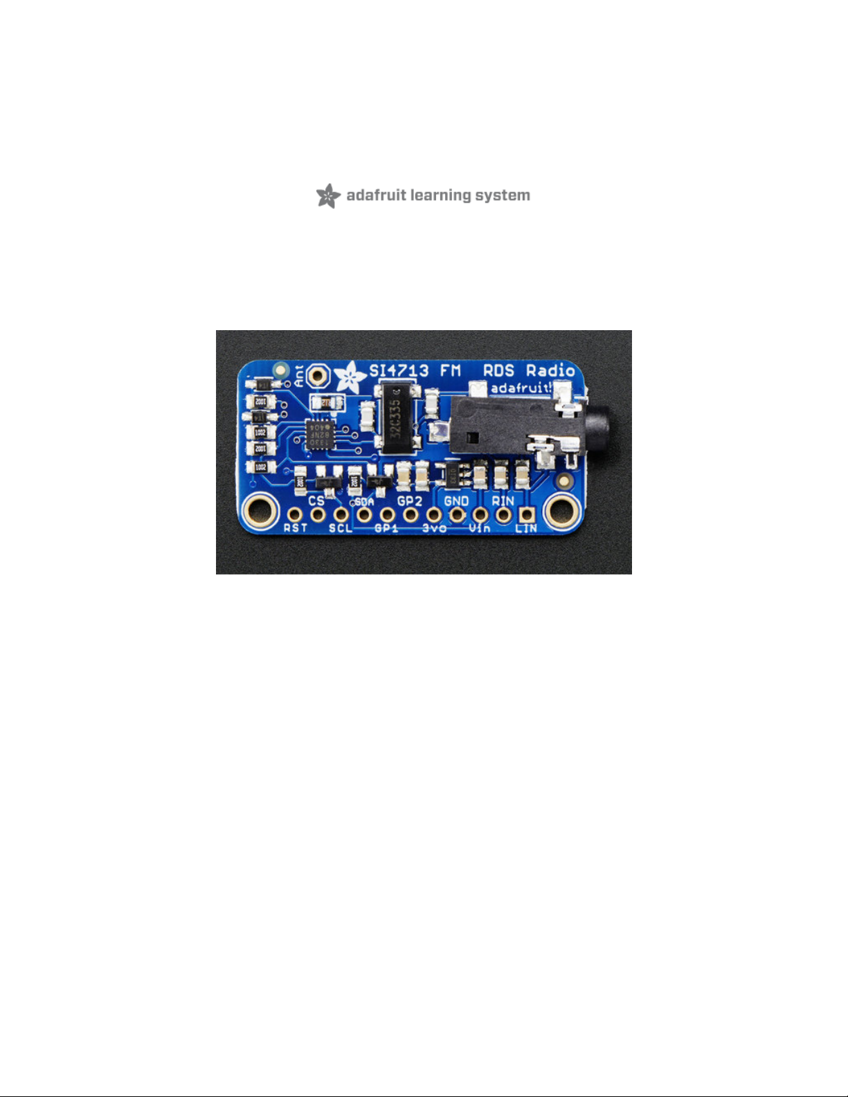
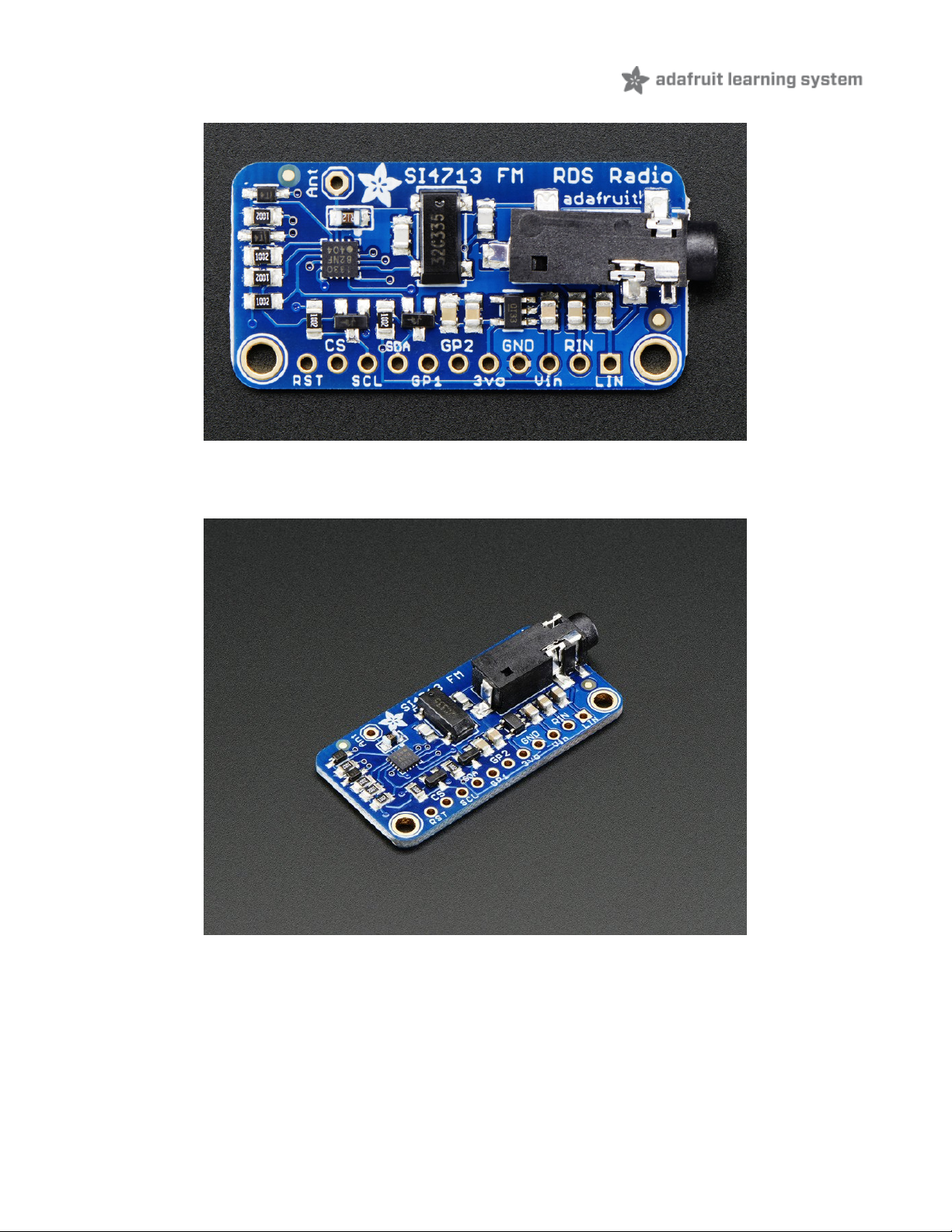
Yaaar! Become your very own pirate radio station with this FM radio transmitter. This breakout board, based on the
best-of-class Si4713, is an all-in-one stereo audio FM transmitter that can also transmit RDS/RBDS data!
Wire up to your favorite microcontroller (we suggest an Arduino) to the I2C data lines to set the transmit frequency and
play line-level audio into the stereo headphone jack. Boom! Now you are the media. Listen using any FM receiver such
as your car or pocket radio receiver - this is an easy way to transmit audio up to about 10 meters / 30 feet away.
© Adafruit Industries
https://learn.adafruit.com/adafruit-si4713-fm-radio-transmitter-with-rds-
rdbs-support
Page 3 of 27
Page 3
This transmitter even has RDS/RBDS support - that's text/data transmissions that many modern FM receivers support.
(It's how some car radios can display the FM station and current song playing). You can transmit just about any text you
want, set the station identifier as well as the 'freeform' buffer.
Best of all, you'll be up and running in minutes with our awesome Arduino library, example code and tutorial!
© Adafruit Industries
https://learn.adafruit.com/adafruit-si4713-fm-radio-transmitter-with-rds-
rdbs-support
Page 4 of 27
Page 4
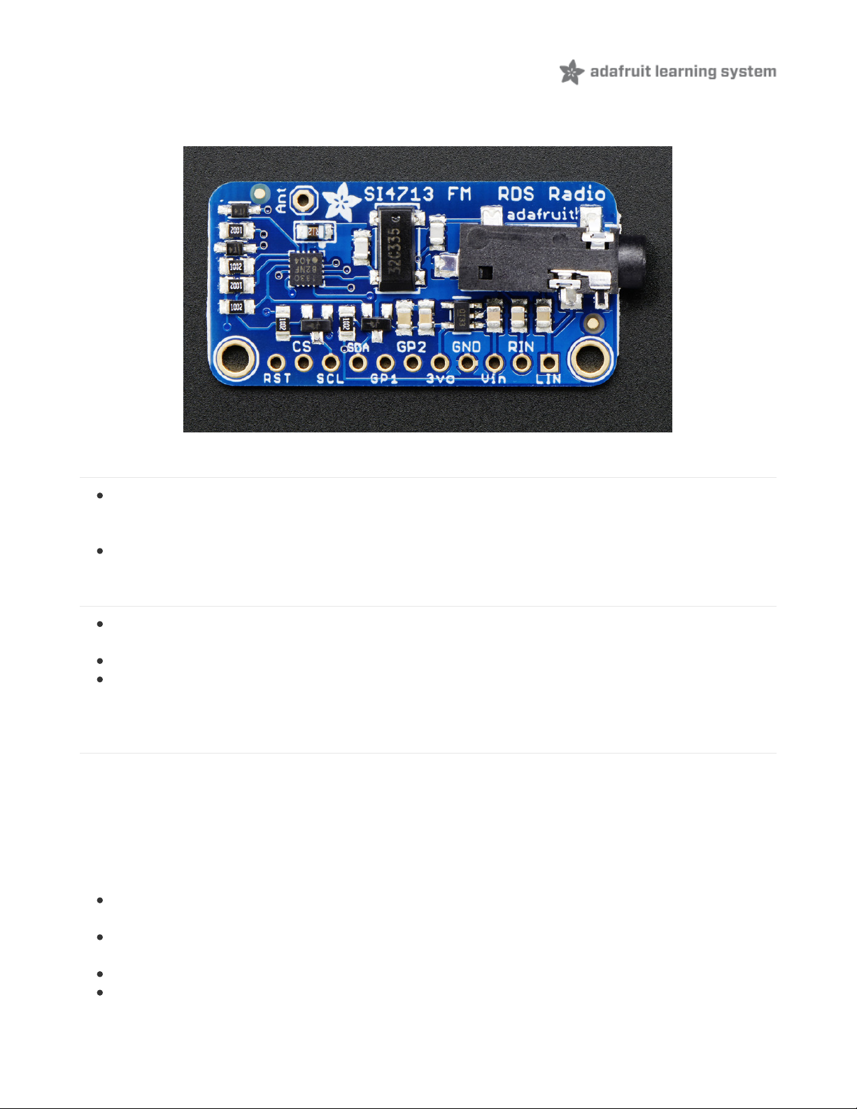
Pinouts
There's a couple pins on this here breakout, lets cover them all in groupings by 'type'
Audio Inputs
LIN - this is the line level LEFT input. Its connected to the headphone jack as well but in case you want to wire
directly without a chunky cable, pipe line level (~0.7 Vpp) audio into here. There's an AC blocking capacitor on
board so it can be DC biased
RIN - same as LIN but the RIGHT input.
Power Pins
Vin - this is the power input pin. You can power the chip from 3-5VDC. Ideally you should use the same voltage
you use for logic levels. For an Arduino, that's usually 5V
GND - this is power and logic ground, connect to your microcontroller's ground pin
3Vo - this is the output from the onboard regulator, 3.3V nominal. You can use this if you need up to 100mA of 3V
regulated voltage
Interface Pins
The FM transmitter chip requires a microcontroller for setting it up unlike pure-analog solutions that have a tuning
potentiometer. The trade off is some code is needed, but the output is digitally tuned so its much more precise.
Our codebase uses I2C to communicate. The chip supports SPI as well but it was annoying enough to support just I2C
so we don't have code examples for SPI!
All the interface input pins are 5V friendly, and can be used with 3-5V logic
RST - This is the Reset pin. You must have this pin toggle before starting to communicate with the chip. When at
logic 0, the chip is in reset.
CS - This is the Chip select pin, used in SPI mode. It also determines the I2C address. When pulled high (it is by
default) the I2C address is 0x63. If this pin is shorted to ground, the I2C address is 0x11
SCL - this is the I2C clock pin, connect to SCL on your microcontroller.
SDA - this is the I2C data pin, connect to SDA on your microcontroller.
© Adafruit Industries
https://learn.adafruit.com/adafruit-si4713-fm-radio-transmitter-with-rds-
rdbs-support
Page 5 of 27
Page 5

Extra GPIO Pins
There's also two "GPIO" pins, you can use these to blink LEDs. The initial state of these pin sets up the chip for Analog
Mode so don't short them to ground or VCC during reset. They are 3V output only!
GP1 - this is GPIO #1
GP2 - this is GPIO #2
GPIO #3 is used for the 32Khz clock generator onboard.
© Adafruit Industries
https://learn.adafruit.com/adafruit-si4713-fm-radio-transmitter-with-rds-
rdbs-support
Page 6 of 27
Page 6
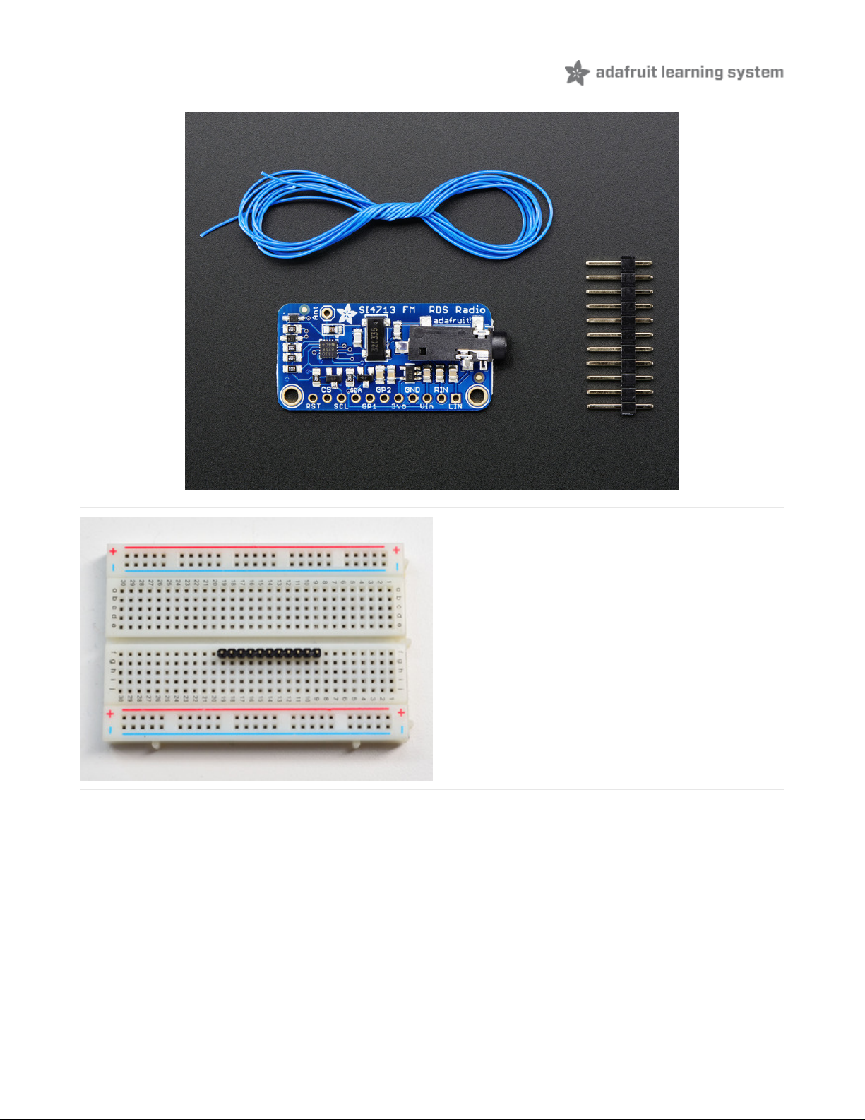
Assembly
Prepare the header strip:
Cut the strip to length if necessary. It will be easier to
solder if you insert it into a breadboard - long pins down
© Adafruit Industries
https://learn.adafruit.com/adafruit-si4713-fm-radio-transmitter-with-rds-
rdbs-support
Page 7 of 27
Page 7
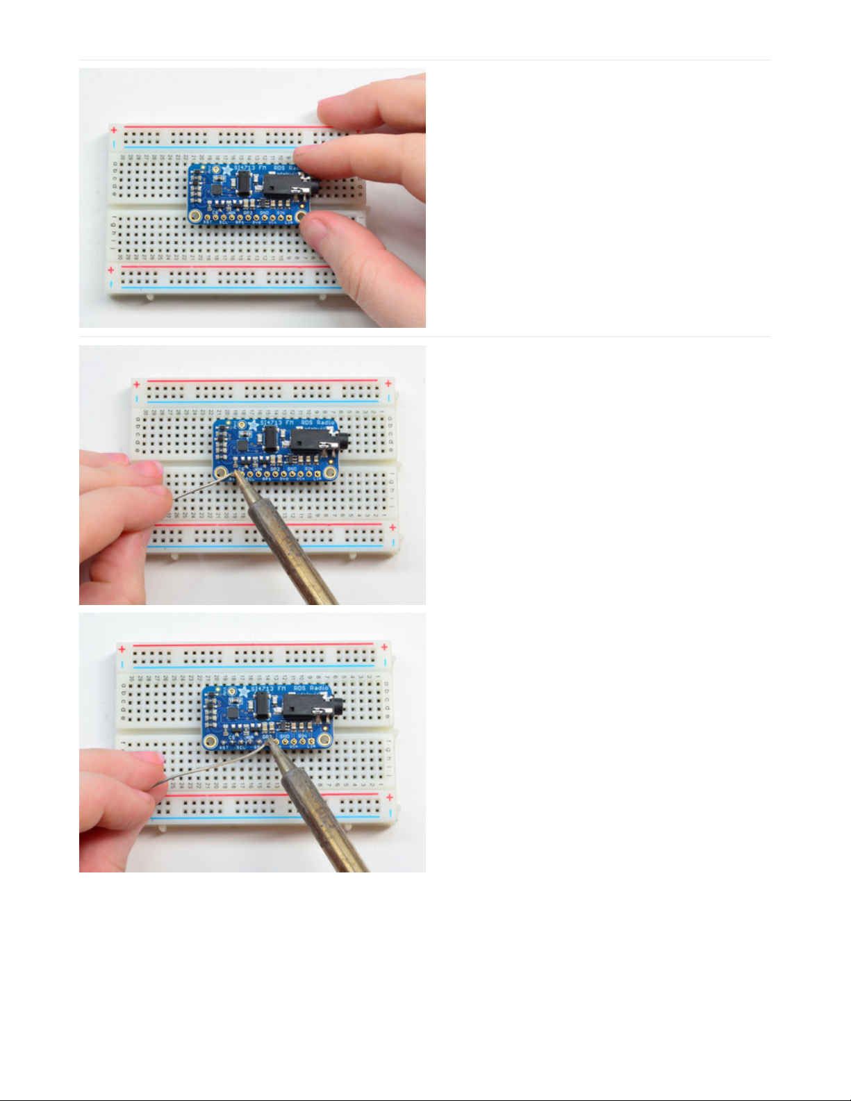
Add the breakout board:
Place the breakout board over the pins so that the short
pins poke through the breakout pads
And Solder!
Be sure to solder all pins for reliable electrical contact.
(For tips on soldering, be sure to check out our Guide to
Excellent Soldering
(https://adafru.it/aTk)
).
© Adafruit Industries
https://learn.adafruit.com/adafruit-si4713-fm-radio-transmitter-with-rds-
rdbs-support
Page 8 of 27
Page 8
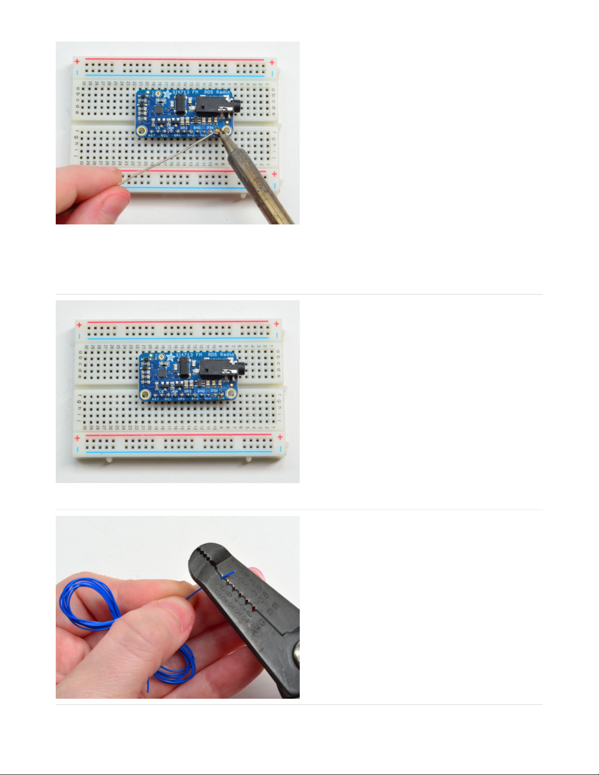
You're done! Check your solder joints visually and
continue onto the antenna
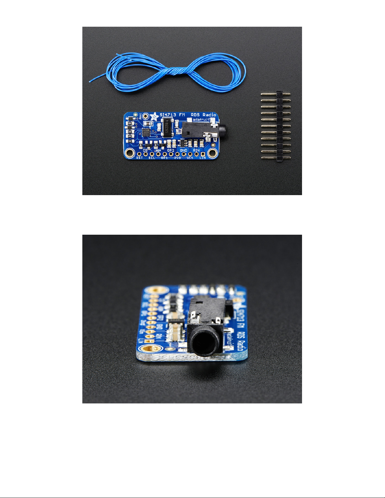
An antenna is required! We provide a 1meter long wire
but you can also use a shorter or longer piece as
desired.
Strip a few mm from the end
© Adafruit Industries
https://learn.adafruit.com/adafruit-si4713-fm-radio-transmitter-with-rds-
rdbs-support
Page 9 of 27
Page 9

Hook the exposed wire end into the ANT hole
Solder it in!
Done!
© Adafruit Industries
https://learn.adafruit.com/adafruit-si4713-fm-radio-transmitter-with-rds-
rdbs-support
Page 10 of 27
Page 10

Arduino Code
Arduino Wiring
You can easily wire this breakout to any microcontroller, we'll be using an Arduino. For another kind of microcontroller,
just make sure it has I2C, then port the code - once the low level i2c functions are adapted the rest should 'fall into
place'
(https://adafru.it/dBn)
Connect Vin to the power supply, 3-5V is fine. Use the same voltage that the microcontroller logic is based off of.
For most Arduinos, that is 5V
Connect GND to common power/data ground
Connect the SCL pin to the I2C clock SCL pin on your Arduino. On an UNO & '328 based Arduino, this is also
known as A5, on a Mega it is also known as digital 21 and on a Leonardo/Micro, digital 3
Connect the SDA pin to the I2C data SDA pin on your Arduino. On an UNO & '328 based Arduino, this is also
known as A4, on a Mega it is also known as digital 20 and on a Leonardo/Micro, digital 2
Connect the RST pin to digital 12 - you can change this later but we want to match the tutorial for now
The Si4713 has a default I2C address of 0x63 - you can change it to 0x11 by connecting CS to ground but don't do that
yet! Get the demo working first before making changes
Download Adafruit_Si4713
To begin reading sensor data, you will need to download the Adafruit si4713 library from the Arduino library manager.
Open up the Arduino library manager:
Search for the Adafruit Si4713 library and install it
We also have a great tutorial on Arduino library installation at:
(https://adafru.it/pOA)
© Adafruit Industries
https://learn.adafruit.com/adafruit-si4713-fm-radio-transmitter-with-rds-
rdbs-support
Page 11 of 27
Page 11
http://learn.adafruit.com/adafruit-all-about-arduino-libraries-install-use (https://adafru.it/aYM)
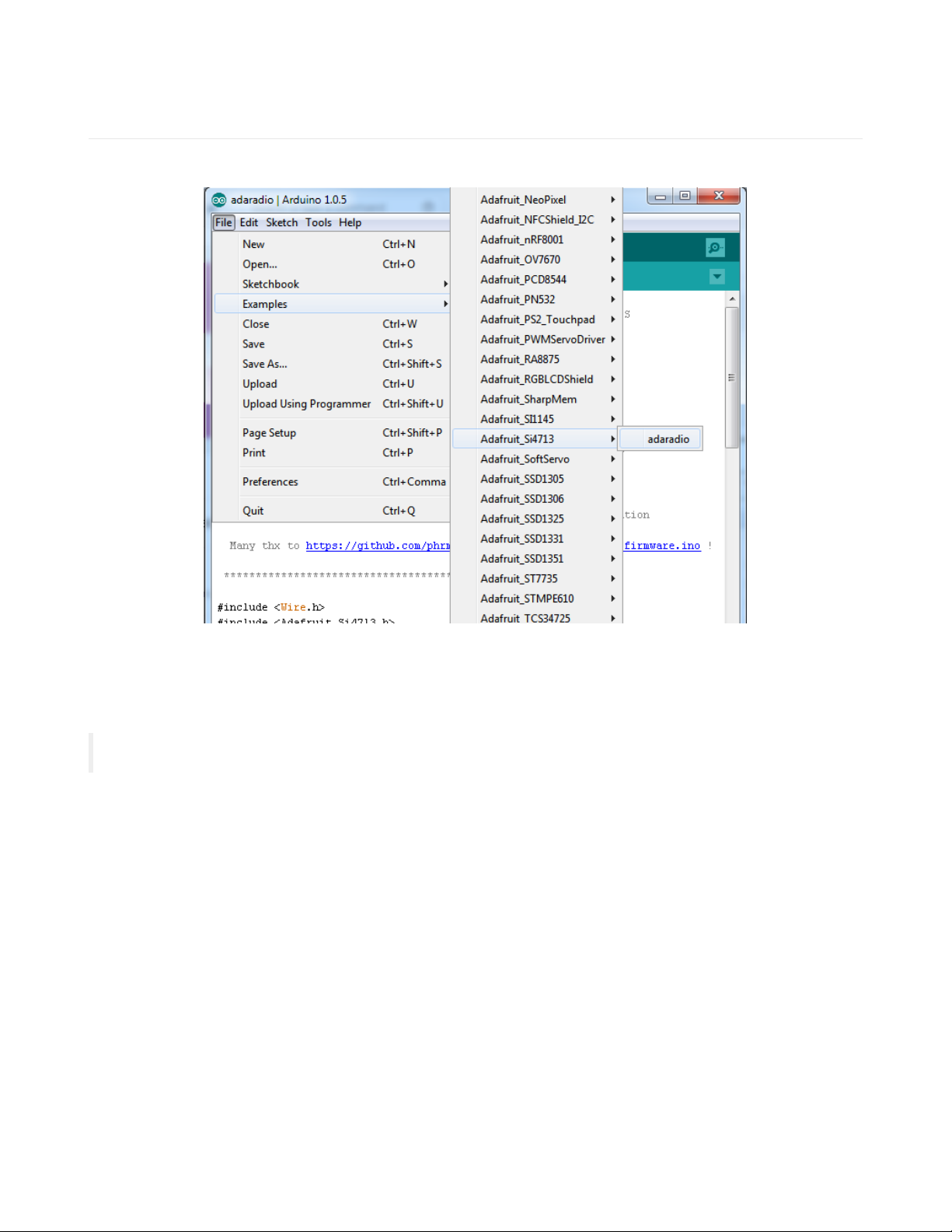
Load Demo
Open up File->Examples->Adafruit_Si4713->adaradio and upload to your Arduino wired up to the sensor
You may want to update the FM station transmission. By default the library transmits on 102.3MHz FM, but that might
be 'taken' in your area.
Find this line
#define FMSTATION 10230 // 10230 == 102.30 MHz
And change it to an unused frequency. This number is in 10KHz so for example 88.1MHz is written as 8810
Upload it to your Arduino and open up the Serial console at 9600 baud
© Adafruit Industries
https://learn.adafruit.com/adafruit-si4713-fm-radio-transmitter-with-rds-
rdbs-support
Page 12 of 27
Page 12

As long as you get to the RDS On! message that means everything works, pipe some audio into the 3.5mm jack and
make sure you see the InLevel audio volume range from 0 to about -10 (dB)
The fastest way to test the RDS message sending is using an RTL-SDR (that's how we debugged the
breakout!) (https://adafru.it/dBr) or a phone/radio that can do RDS decoding
© Adafruit Industries
https://learn.adafruit.com/adafruit-si4713-fm-radio-transmitter-with-rds-
rdbs-support
Page 13 of 27
Page 13

Using the RPS Scanning function
The Si4713 has the ability 'scan' the FM band and measure the input power. You can use the RPS functionality to
locate a good unused station. Find this section in the adaradio demo and uncomment the for loop:
// Uncomment below to scan power of entire range from 87.5 to 108.0 MHz
/*
for (uint16_t f = 8750; f<10800; f+=10) {
radio.readTuneMeasure(f);
Serial.print("Measuring "); Serial.print(f); Serial.print("...");
radio.readTuneStatus();
Serial.println(radio.currNoiseLevel);
}
*/
Reupload and look at the serial console:
© Adafruit Industries
https://learn.adafruit.com/adafruit-si4713-fm-radio-transmitter-with-rds-
rdbs-support
Page 14 of 27
Page 14
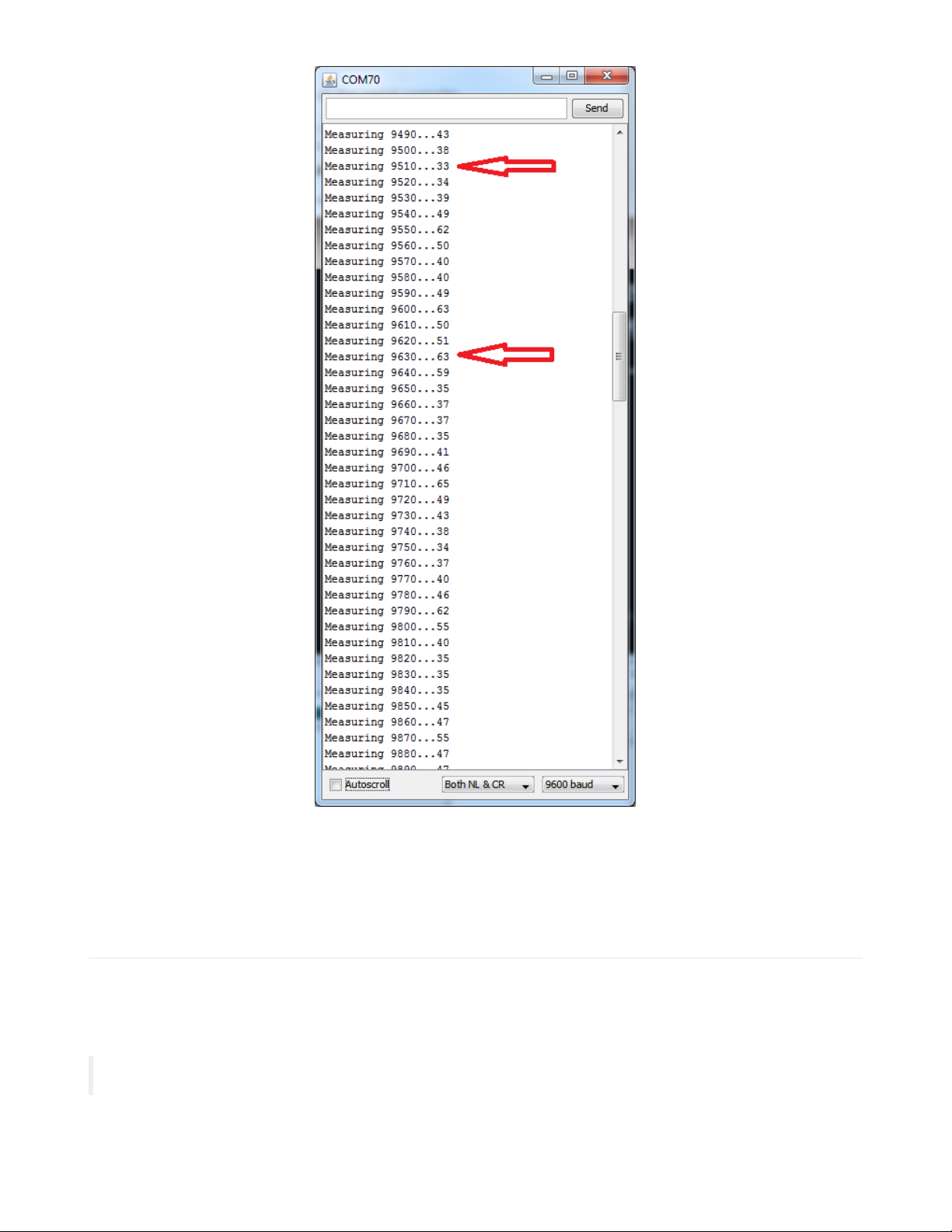
The larger the number the higher the transmission power. For example, 96.3MHz is a higher number than the others
(FYI, its Univision 96.3 FM (https://adafru.it/dBs)!) whereas 95.1 MHz is nice as low, that's not used for any transmission.
Try to find a number that's also not surrounded by high numbers, since it can get 'drowned out' by the nearby
frequencies.
Library Reference
Radio Transmitter control
Start out by initializing the Si4713 chipset with
begin()
© Adafruit Industries
https://learn.adafruit.com/adafruit-si4713-fm-radio-transmitter-with-rds-
rdbs-support
Page 15 of 27
Page 15

This will return true if the radio initialized, and false if the radio was not found. Check your wiring if its not 'showing up'
Then you can turn on the radio transmitter with
setTXpower(txpwr)
the txpwr number is the dBμV transmission power. You can set this to 88-115dBμV or 0 (for off)
Of course, you'll want to tune the transmitter! Do that with
tuneFM(
freq
)
That will set the output frequency, in 10's of KHz. So if you want to tune to 101.9 the frequency value is 10190
You can check in on the radio with
readTuneStatus()
Whcih will set the
currFreq currdBuV
adnd
currAntCap
variables in the radio object. The first two are the frequency
and power output, the third variable is the tuning antenna capacitor it set for the best output. This number will vary with
antenna size and frequency.
RPS (Radio Power Sensing)
This function is used with two procedures.
readTuneMeasure(freq)
begins the measurement, freq is in units of 10KHz so 88.1MHz is written in as 8810
Then you have to call
readTuneStatus()
which will wait until the chip has measured the data and stick it into the
currNoiseLevel
variable
RDS/RBDS (Radio Data Broadcast)
The Si4713 has great support for sending RDS data and we made it real easy too. Initialize the subsystem with
beginRDS()
Then you can set the "station name" with
setRDSstation("AdaRadio")
The radio station name is up to 8 characters
You can also send the main buffer which usually contains the song name/artist.
setRDSbuffer( "Adafruit g0th Radio!")
You can send up to 32 characters, but you can continuously send new data, just wait a few seconds before each data
rewrite so the listener's radio has received all the data
© Adafruit Industries
https://learn.adafruit.com/adafruit-si4713-fm-radio-transmitter-with-rds-
rdbs-support
Page 16 of 27
Page 16

GPIO Control
There's two GPIO pins you can use to blink LEDs. They are GPIO1 and GPIO2 - GPIO3 is used for the oscillator. To set
them to be outputs call
setGPIOctrl(
bitmask
)
where the bitmask has a 1 bit for each of the two pins. For example to set GPIO2 to be an output use setGPIOctrl((1<<2))
to set both outputs, use setGPIOctrl((1<<2) || (1<<1))
Then you can set the output with
setGPIO(
bitmask
)
same idea with the bitmask, to turn both on, use setGPIOctrl((1<<2) || (1<<1)). To turn GPIO2 on and GPIO1 off,
setGPIOctrl(1<<2)
Advanced!
We, by default, use the built-in AGC (auto-gain control) system so the audio level is maxed out. This may be annoying
to you if have a good quality line level and the volume is fluctuating (it should be quiet, but isnt)
in the Adafruit_Si4713.cpp file find these lines
//setProperty(SI4713_PROP_TX_ACOMP_ENABLE, 0x02); // turn on limiter, but no dynamic ranging
setProperty(SI4713_PROP_TX_ACOMP_ENABLE, 0x0); // turn on limiter and AGC
and uncomment the first one, and comment the second. This will turn off the AGC
© Adafruit Industries
https://learn.adafruit.com/adafruit-si4713-fm-radio-transmitter-with-rds-
rdbs-support
Page 17 of 27
Page 17

Python & CircuitPython
It's easy to use the Si4713 FM transmitter with Python or CircuitPython, and the Adafruit CircuitPython
SI4713 (https://adafru.it/Bq7) module. This module allows you to easily write Python code that controls the transmitter
and sends RDS data.
You can use this sensor with any CircuitPython microcontroller board or with a computer that has GPIO and Python
thanks to Adafruit_Blinka, our CircuitPython-for-Python compatibility library (https://adafru.it/BSN).
CircuitPython Microcontroller Wiring
First wire up a Si4713 to your board exactly as shown on the previous pages for Arduino using an I2C connection.
Here's an example of wiring a Feather M0 to the sensor with I2C:
Board 3V to sensor VIN
Board GND to sensor GND
Board SCL to sensor SCL
Board SDA to sensor SDA
Board D5 to sensor RST
Python Computer Wiring
Since there's
dozens
of Linux computers/boards you can use we will show wiring for Raspberry Pi. For other platforms,
please visit the guide for CircuitPython on Linux to see whether your platform is supported (https://adafru.it/BSN).
Here's the Raspberry Pi wired with I2C:
Pi 3V3 to sensor VIN
Pi GND to sensor GND
Pi SCL to sensor SCL
Pi SDA to sensor SDA
Pi GPIO5 to sensor RST
CircuitPython Installation of SI4713 Library
Next you'll need to install the Adafruit CircuitPython SI4713 (https://adafru.it/Bq7) library on your CircuitPython board.
First make sure you are running the latest version of Adafruit CircuitPython (https://adafru.it/Amd) for your board.
Next you'll need to install the necessary libraries to use the hardware--carefully follow the steps to find and install these
libraries from Adafruit's CircuitPython library bundle (https://adafru.it/zdx). Our introduction guide has a great page on
how to install the library bundle (https://adafru.it/ABU) for both express and non-express boards.
© Adafruit Industries
https://learn.adafruit.com/adafruit-si4713-fm-radio-transmitter-with-rds-
rdbs-support
Page 18 of 27
Page 18

Remember for non-express boards like the, you'll need to manually install the necessary libraries from the bundle:
adafruit_si4713.mpy
adafruit_bus_device
Before continuing make sure your board's lib folder or root filesystem has
the adafruit_si4713.mpy, and adafruit_bus_device files and folders copied over.
Next connect to the board's serial REPL (https://adafru.it/Awz) so you are at the CircuitPython >>> prompt.
Python Installation of SI4713 Library
You'll need to install the Adafruit_Blinka library that provides the CircuitPython support in Python. This may also
require enabling I2C on your platform and verifying you are running Python 3. Since each platform is a little different,
and Linux changes often, please visit the CircuitPython on Linux guide to get your computer
ready (https://adafru.it/BSN)!
Once that's done, from your command line run the following command:
sudo pip3 install adafruit-circuitpython-si4713
If your default Python is version 3 you may need to run 'pip' instead. Just make sure you aren't trying to use
CircuitPython on Python 2.x, it isn't supported!
CircuitPython & Python Usage
To demonstrate the usage of the sensor we'll initialize it and control the transmitter from the board's Python REPL.
Run the following code to import the necessary modules and initialize the I2C connection with the sensor:
import board
import busio
import adafruit_si4713
i2c = busio.I2C(board.SCL, board.SDA)
si_reset = digitalio.DigitalInOut(board.D5)
si4713 = adafruit_si4713.SI4713(i2c, reset=si_reset, timeout_s=0.5)
Frequency Strength Scan
One interesting thing you can do with the Si4713 is measure the quality of an FM radio band. This is handy for example
to 'scan' the entire range of FM frequencies looking for possible radio station broadcasts (i.e. frequencies with a good
quality signal). This can help you find an unused frequency band to use for your transmitting.
The received_noise_level function can be called with a frequency (specified in kilohertz and only at 50khz steps) and
will return the noise level, or signal quality, in dBuV units. The radio supports a range of frequencies from 87.5mhz to
108mhz and you can scan them all with this code:
for f_khz in range(87500, 108000, 50):
noise = si4713.received_noise_level(f_khz)
print('{0:0.3f} mhz = {1} dBuV'.format(f_khz/1000.0, noise))
© Adafruit Industries
https://learn.adafruit.com/adafruit-si4713-fm-radio-transmitter-with-rds-
rdbs-support
Page 19 of 27
Page 19

The higher the dBuV noise value the stronger the signal and better chance there's a real station broadcasting there.
The exact values will differ based on your area and the nearby stations but in general a small value under 32 is
probably unused, and a large value above 40 is a strong radio signal. Notice in the screen shot above 107.7mhz has a
strong signal with noise value of 45 dBuV, this makes sense because a nearby FM station, Seattle's 107.7mhz FM The
End (https://adafru.it/Bq9), is broadcasting at that frequency. However at 107.35mhz the signal has a much smaller
noise value of 29 and likely indicates an unused frequency.
Transmitting
Once you find a frequency that's unused you can configure the transmitter to broadcast its audio input on it with the
tx_frequency_khz property. Set this to a value in kilohertz, again only within the range 87.5mhz - 108mhz and at
50khz steps, to change the transmitter frequency. For example to use 107.35mhz:
si4713.tx_frequency_khz = 107350
You can also set the transmitter power with the tx_power property. Set this to a dBuV value from 88 - 115, or set 0 to
turn off the transmitter entirely. You typically want the maximum power because these low power FM transmitters
don't have much range by design. For example to set the maximum 115 dBuV transmit power:
si4713.tx_power = 115
At this point the Si4713 should be transmitting anything sent to the audio jack or LIN & RIN inputs over the configured
FM frequency. Plug in an audio source and try tuning an FM radio nearby to hear the signal! Remember the range of
these low power FM transmitters is limited and you might need the radio in the very same room or close by to pick up
the signal.
You might need to increase or decrease the volume of your audio source to ensure it's at a high enough level for the
transmitter to pick up and send (or you might need to turn it down if it's too high and 'overmodulating' the FM signal).
You can actually check with the chip to see if it's getting a good audio signal and potentially overmodulating or running
into other transmission issues. Simply read the input_level property to see the audio level (in dB) and the
audio_signal_status property to check if there are problems with the signal:
© Adafruit Industries
https://learn.adafruit.com/adafruit-si4713-fm-radio-transmitter-with-rds-
rdbs-support
Page 20 of 27
Page 20

print('Audio level: {0} dB'.format(si4713.input_level))
print('Audio signal status: 0x{0:02x}'.format(si4713.audio_signal_status))
Notice the input level is around -16 dB which is a typical value for audio (lower values mean less volume / input level
and higher values up to 0 or more mean very loud input). The audio signal status is a byte that has a few bits to
indicate status, in particular the 3rd bit will be turned on to indicate overmodulation (an easy way to check is if the
value of the signal status is 4 or greater, that indicates bit 3 is on).
Try cranking up the audio source volume and notice the audio level value increases and the overmodulation bit turns
on to indicate the volume is too high (remember a value 4 or greater means the input is overmodulating):
You should aim to keep the input level around -20 to -10 dB and ensure the overmodulation bit isn't set (if it is then the
volume is too high).
RDS - Radio Data System
Finally the RDS features of the Si4713 allow you to transmit data along with the FM audio signal. This is transferred in
special side channels to the main FM broadcast and include data like the name of the station and the currently playing
song. If you've ever seen a car radio that prints the name of a song being played it's probably reading it over an RDS
transmission from the radio station.
You can easily configure and set the RDS transmission of the Si4713 with the configure_rds function. For example:
si4713.configure_rds(0xADAF, b'AdaFruit Radio', b'AdaFruit g0th Radio!')
This call takes the following parameters:
The station ID - This is a 16-bit value that the tuner can use to identify a station. In this case we're sending the
value 0xADAF.
The station name - This is an optional keyword argument that can specify a byte string with the station name to
broadcast. You can only send up to 96 characters with this value.
The buffer value - This is another optional keyword argument that can specify a byte string to broadcast as the
current RDS buffer (typically shown as the song or now playing string on a radio). You're limited to 106
characters with this value.
Once you call configure_rds it will enable the RDS broadcast and configure itself to do so at typical North American
RDS radio broadcast values (i.e. a specific frequency deviation, repeat interval, etc.). After RDS is configured you can
update the station and buffer values by writing to the rds_station and rds_buffer properties respectively. Remember
each is limited to a length of 96 characters and 106 characters respectively:
si4713.rds_station = b'Mosfet Jams'
si4713.rds_buffer = b'Purrfect tunes!'
© Adafruit Industries
https://learn.adafruit.com/adafruit-si4713-fm-radio-transmitter-with-rds-
rdbs-support
Page 21 of 27
Page 21

That's all there is to the basic Si4713 usage with CircuitPython!
Below is a complete demo that will configure the board for FM transmission at a specified frequency (see the
FREQUENCY_KHZ variable at the top). It will broadcast RDS data and periodically print audio input level and signal
quality status. In addition it also shows basic usage of the GPIO outputs of the Si4713 with the gpio_control and
gpio_set functions--these aren't commonly used but are available if you need a couple small outputs from the board.
Save this as code.py on your board.
Full Example Code
# Simple demo of using the SI4743 RDS FM transmitter.
# Author: Tony DiCola
import time
import board
import busio
import digitalio
import adafruit_si4713
# Specify the FM frequency to transmit on in kilohertz. As the datasheet
# mentions you can only specify 50khz steps!
FREQUENCY_KHZ = 102300 # 102.300mhz
# Initialize I2C bus.
i2c = busio.I2C(board.SCL, board.SDA)
# Initialize SI4713.
# si4713 = adafruit_si4713.SI4713(i2c)
# Alternatively you can specify the I2C address of the device if it changed:
# si4713 = adafruit_si4713.SI4713(i2c, address=0x11)
# If you hooked up the reset line you should specify that too. Make sure
# to pass in a DigitalInOut instance. You will need the reset pin with the
# Raspberry Pi, and probably other devices:
si_reset = digitalio.DigitalInOut(board.D5)
print("initializing si4713 instance")
si4713 = adafruit_si4713.SI4713(i2c, reset=si_reset, timeout_s=0.5)
print("done")
# Measure the noise level for the transmit frequency (this assumes automatic
# antenna capacitance setting, but see below to adjust to a specific value).
noise = si4713.received_noise_level(FREQUENCY_KHZ)
# Alternatively measure with a specific frequency and antenna capacitance.
# This is not common but you can specify antenna capacitance as a value in pF
# from 0.25 to 47.75 (will use 0.25 steps internally). If you aren't sure
# about this value, stick with the default automatic capacitance above!
# noise = si4713.received_noise_level(FREQUENCY_KHZ, 0.25)
print("Noise at {0:0.3f} mhz: {1} dBuV".format(FREQUENCY_KHZ / 1000.0, noise))
# Tune to transmit with 115 dBuV power (max) and automatic antenna tuning
# capacitance (default, what you probably want).
si4713.tx_frequency_khz = FREQUENCY_KHZ
si4713.tx_power = 115
© Adafruit Industries
https://learn.adafruit.com/adafruit-si4713-fm-radio-transmitter-with-rds-
rdbs-support
Page 22 of 27
Page 22

# Configure RDS broadcast with program ID 0xADAF (a 16-bit value you specify).
# You can also set the broadcast station name (up to 96 bytes long) and
# broadcast buffer/song information (up to 106 bytes long). Setting these is
# optional and you can later update them by setting the rds_station and
# rds_buffer property respectively. Be sure to explicitly specify station
# and buffer as byte strings so the character encoding is clear.
si4713.configure_rds(0xADAF, station=b"AdaRadio", rds_buffer=b"Adafruit g0th Radio!")
# Print out some transmitter state:
print("Transmitting at {0:0.3f} mhz".format(si4713.tx_frequency_khz / 1000.0))
print("Transmitter power: {0} dBuV".format(si4713.tx_power))
print(
"Transmitter antenna capacitance: {0:0.2} pF".format(si4713.tx_antenna_capacitance)
)
# Set GPIO1 and GPIO2 to actively driven outputs.
si4713.gpio_control(gpio1=True, gpio2=True)
# Main loop will print input audio level and state and blink the GPIOs.
print("Broadcasting...")
while True:
# Print input audio level and state.
print("Input level: {0} dBfs".format(si4713.input_level))
print("ASQ status: 0x{0:02x}".format(si4713.audio_signal_status))
# 'Blink' GPIO1 and GPIO2 alternatively on and off.
si4713.gpio_set(gpio1=True, gpio2=False) # GPIO1 high, GPIO2 low
time.sleep(0.5)
si4713.gpio_set(gpio1=False, gpio2=True) # GPIO1 low, GPIO2 high
time.sleep(0.5)
© Adafruit Industries
https://learn.adafruit.com/adafruit-si4713-fm-radio-transmitter-with-rds-
rdbs-support
Page 23 of 27
Page 23

Python
Docs
Python Docs (https://adafru.it/C5B)
© Adafruit Industries
https://learn.adafruit.com/adafruit-si4713-fm-radio-transmitter-with-rds-
rdbs-support
Page 24 of 27
Page 24

Downloads
Datasheets & Files
Si4713 Datasheet (https://adafru.it/dBc)(this does not include any software interfacing details)
Si47xx Programming guide (https://adafru.it/Bqa) - contains all the nitty-gritty details on command data packets
etc.
Fritzing object in Adafruit Fritzing library (https://adafru.it/c7M)
EagleCAD PCB files in GitHub (https://adafru.it/pOB)
Layout Print
Dimensions in Inches
Schematic
© Adafruit Industries
https://learn.adafruit.com/adafruit-si4713-fm-radio-transmitter-with-rds-
rdbs-support
Page 25 of 27
Page 25

© Adafruit Industries
https://learn.adafruit.com/adafruit-si4713-fm-radio-transmitter-with-rds-
rdbs-support
Page 26 of 27
Page 26

© Adafruit Industries Last Updated: 2020-10-27 10:20:26 PM EDT Page 27 of 27
 Loading...